

Nobel FCD 15, FCD 11, FCD 30, FCD 40, FCD 50 Instruction Manual
...
FCD/DT
FACD/DT
FFD/DT
AUTOMATIC FILTERS
FCD/DP
FACD/DP
FFD/DP
FCD/DT-DUAL
FACD/DT-DUAL
FFD/DT-DUAL
FCD/DP-DUAL
FACD/DP-DUAL
FFD/DP-DUAL
INSTRUCTIONS MANUAL
WARNING!
The equipment must be used only for the utilization for which they have been
designed, as shown in the technical documentation.
Read carefully this leaflet until the end before starting any operation.
Proceed strictly according to all directions included in this manual.
Automatic filters series FCD, FACD and FFD are designed to treat raw water supplied
from municipalities or from well.
ANY OTHER APPLICATIONS OF THE EQUIPMENT DIFFERENT THAN THE MENTIONED
ONES IS MADE UNDER THE ONLY RESPONSIBILITY OF THE USER.
For any assistance concerning the installations, maintenance or utilization of the equipment
apply the NOBEL Service Center closest to you or directly :
NOBEL S.r.l. via Monfalcone 8 – I-20132 Milano
tel. +39 02 2827968 fax +39 02 2610839
rev. 4
Page 1 of 23 fcd-dp_mi-r4.doc

INSTRUCTIONS MANUAL AUTOMATIC FILTERS
FCD-FACD-FFD /DT /DP /DT-DUAL /DP-DUAL
INDEX
1. SAFETY...................................................................................................................................................3
1.1. General...............................................................................................................................................3
1.2. How to displace the unit .....................................................................................................................3
1.3. Hydraulics...........................................................................................................................................3
1.4. Electrical.............................................................................................................................................3
1.5. How to store and delivery...................................................................................................................3
2. PRINCIPLES OF WORKING ..................................................................................................................4
2.1. Quartz-sand filters FCD .....................................................................................................................4
2.2. Activated-carbon filters FACD............................................................................................................4
2.3. Iron removal filters FFD......................................................................................................................5
3. TECHNICAL CHARACTERISTICS.........................................................................................................5
3.1. Assumed raw water characteristics ...................................................................................................5
3.2. Technical characteristics (general) ....................................................................................................5
3.3. Characteristics for each model ..........................................................................................................6
3.4. Dimensions.........................................................................................................................................7
3.5. Weights ..............................................................................................................................................7
4. INSTALLATION.......................................................................................................................................8
4.1. How to remove packaging..................................................................................................................8
4.2. How to move and lift the unit..............................................................................................................8
4.3. Placing & commissioning ...................................................................................................................8
4.4. Hydraulic connections ........................................................................................................................9
4.5. How to load the media filter..............................................................................................................10
4.6. Electrical wiring connections............................................................................................................11
5. END CYCLE AND REGENERATION ...................................................................................................12
5.1. End cycle at time (for all version) .....................................................................................................12
5.2. End cycle at pressure drop (only for version DP e DP-DUAL) ........................................................12
5.3. Regeneration....................................................................................................................................12
5.4. Inhibit of the regeneration ................................................................................................................13
5.5. Inhibition of the water supply............................................................................................................13
6. CONTROL PANEL ................................................................................................................................14
6.1. Functions of the logical programmer................................................................................................14
6.2. Signals on the display of the programmer .......................................................................................15
7. SETTINGS.............................................................................................................................................16
7.1. How to set language ........................................................................................................................16
7.2. How to set current time and day of the week...................................................................................16
7.3. How to set day and time of regeneration .........................................................................................17
7.4. How to set time of phases, delay, pressure drop value ...................................................................17
7.5. How to set parameters switch (ON/OFF).........................................................................................18
7.6. Factory set........................................................................................................................................18
8. STARTING-UP ......................................................................................................................................19
9. SERVICE & MAINTENANCE................................................................................................................20
9.1. Media filter, nozzles .........................................................................................................................20
9.2. Disposal............................................................................................................................................21
10. MAIN COMPONENTS...........................................................................................................................21
11. TROUBLE-SHOOTING GUIDE ............................................................................................................23
Annex
• DRAWING 1: dimensions • WIRING DIAGRAM
• DRAWING 2: components models
FCD05÷FCD11, FACD05÷FACD11, FFD04 and FFD06
• DRAWING 3: components models
FCD15÷FCD80, FACD15÷FACD60, FFD08÷FFD40
• DRAWING 4: installation models
FCD05÷FCD11, FACD05÷FACD11, FFD04 and FFD06
• DRAWING 5: installation models
FCD15÷FCD80, FACD15÷FACD60, FFD08÷FFD40
• DRAWING transducers installation (only for version DP e DP-DUAL)
• running test certificate
• solenoid valves manual
• diaphragm valves manual
s.r.l.Milano - ITALY Page 2 of 23 fcd-dp_mi-r4.doc – r.4

INSTRUCTIONS MANUAL AUTOMATIC FILTERS
FCD-FACD-FFD /DT /DP /DT-DUAL /DP-DUAL
1. SAFETY
1.1. General
The equipment has been designed and constructed according to D.P.R. n° 459 of 24th July
1996 (regulation for accomplishment of Norms 2006/42/CE, 91/368/CE, 93/44/CE and 93/68/CE
regarding the unification of States members laws in so far as machines are concerned).
It has been designed and constructed according to European Norms UNI EN 292-1, UNI EN
292-2, UNI EN 292-2/A1, UNI EN 983, CEI EN 60439-1, CEI EN 60 204-1.
Only authorized and skilled personnel will be allowed to carry out installation, start up as well
as routine and planned maintenance.
1.2. How to displace the unit
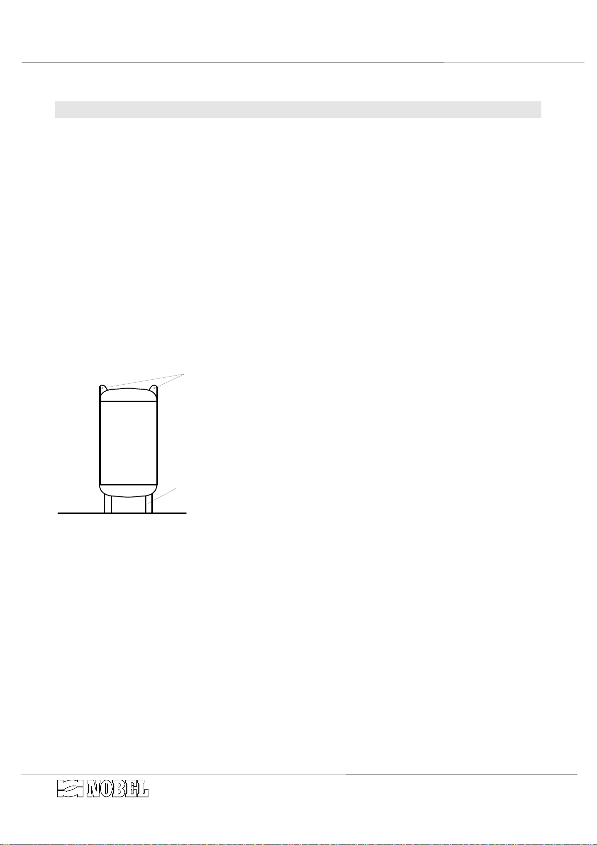
Particular care and attention should be put in during moving and displacing of heavy items, in
order to avoid injuries to persons or damage (see § 3.5 pag. 7). The heavy parts must be lifted
and displaced always hooking and lifting them by the points shown on the drawings (see fig. 1)
and using only suitable ropes, hooks and/or chains, according to the weight (see weight table).
1.3. Hydraulics
All operations must be performed by and/or under direct supervision of skilled and authorized
operators, using proper tools and personal protection devices if required (CE marked).
Before any operation of taking out pipes or part of hydraulic system, it is required to release
the pressure inside and empty the part of the system.
1.4. Electrical
Before starting any operation on electrical devices, be sure that main power supply is OFF.
All operations must be performed by skilled and authorized operators.
In case of liquid leakage, switch off the main power supply before operate. Before the
switching ON, be sure all the parts of the system are perfectly dry. Check that the available
electrical power is correct before connection. Do not make preliminary wiring connections.
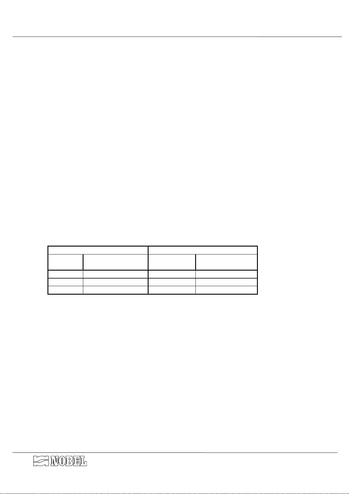
1.5. How to store and delivery
• closed rooms
• open space
• transport
• installation
t = ºC t = ºF humidity rel. notes
5÷45 41÷113 5÷95%
5÷45 41÷113 5÷95%
5÷45 41÷113 5÷95%
5÷45 41÷113 5÷95%
without condensate
without condensate
without condensate
without condensate
protect from sun-light and rain.
protect from sun-light and rain.
protect from sun-light and rain.
s.r.l.Milano - ITALY Page 3 of 23 fcd-dp_mi-r4.doc – r.4

INSTRUCTIONS MANUAL AUTOMATIC FILTERS
FCD-FACD-FFD /DT /DP /DT-DUAL /DP-DUAL
2. PRINCIPLES OF WORKING
FCD, FACD and FCD series filters (on versio DT, DT-DUAL, DP and DP-DUAL) are used for
water treatment for residential and industrial applications as well. All the materials are food
grade and approved for drinking water.
2.1. Quartz-sand filters FCD
The filtration through a sand media is a mechanical process that allows to remove suspended solids
(even of small dimensions) from water.
The slower is the linear flow (speed of water trough the filtering bed), the better is the filtration action.
During the process, as the filtering bed traps the suspended particles, as filtration action increases,
since the trapped solids works the same way of a filtering bed!
But it also increases the resistance of the filtering bed against the water flow; so the pressure drop
between inlet and outlet increases as well.
The maximum allowed pressure drop is 1 bar (100 kPa), after that it is required to backwash the
filtering bed.
The purpose of the backwashing is to re-built the filtering bed efficiency, by removing the solids
trapped during service; it is featured by a counter-flow of water through the filtering bed.
The programmer allows to set the regeneration at the scheduled days and time; for DP and DP-DUAL
models, regeneration can also be set to start when the max allowable value of pressure drop is reached.
For the best working of the filter, the backwashing must be featured before the pressure drop
reaches the threshold level (1 bar - 100 kPa).
During regeneration the water supplying is completely inhibited by means of a membrane valve
mounted on the outlet line.
2.2. Activated-carbon filters FACD
Filtration through a bed of activated carbon is the process that allows to remove organic matters and
chlorine from water.
The lower is the flow rate, the better is the filtration action.
FACD series filters are designed and sized for chlorine removal. The expected life of activated-carbon
used as de-chlorination (chlorine removal) is very long; it works as chemical reduction of chlorine to
chloride ion.
Activated carbon action is not selective in removing the substances contained in water and crossing
the filtering bed: hence, it removes also the organics the water contains, if any.
Therefore, it could happen that the filtering bed is exhausted or clogged by the trapping of substances
contained in water, even if the purpose of treatment was not the removal of these substances, but just the
de-chlorination.
Furthermore, it could happen that the filtering bed releases some of the substances previously trapped
in higher concentration than before.
Since it is quite impossible to forecast the exhaustion of the activated carbon bed, or to monitor the
exhaustion itself, with current instrumentation, the utilization of an activated carbon filter must be strictly
avoided without adequate pre-treatments, like quartz-sand filtration, chlorination, etc.
Whether raw water contains organics and/or is biologically polluted, FACD series filters CANNOT
used without written authorization by NOBEL Technical Department.
The activated-carbon bed also works as a mechanic filter same way of quartz-sand bed.
Although this working should be avoided, it can happen that the pressure drop of activated-carbon bed
reaches a value of 1 bar (100 kPa); in this case the backwashing of the filtering bed is required.
The programmer allows to set the regeneration at the scheduled days and time; for DP and DP-DUAL
models, regeneration can also be set to start when the max allowable value of pressure drop is reached.
For the best working of the filter, the backwashing must be featured before the pressure drop
reaches the threshold level (1 bar - 100 kPa).
It is recommended to run the regeneration only when it is strictly required: the backwashing causes
the mixing of the bed and could displace the higher layers of activated carbon (most polluted) from the
top to the bottom of the column.
During regeneration the water supplying is completely inhibited by means of a membrane valve
mounted on the outlet line.
s.r.l.Milano - ITALY Page 4 of 23 fcd-dp_mi-r4.doc – r.4
be

INSTRUCTIONS MANUAL AUTOMATIC FILTERS
FCD-FACD-FFD /DT /DP /DT-DUAL /DP-DUAL
2.3. Iron removal filters FFD
Iron removal filters series FFD are used for water treatment for residential and industrial
applications as well. All the materials, media filter included, are food grade and approved for
drinking water. The range of models includes systems with capacity from 4.0 up to 40.0 m³/h.
Iron removing is the process of filtration that allows to remove iron and manganese from
water. This special filtration is made through a special catalytic media filter, (activated
pyrolusite, briefly successively named PL, mixed with quartz-sand) which action is to oxide and
then filter the dissolved iron and manganese.
The media filter is kept in its activated state by mean of an oxiding agent, oxigen or
hypochlorite, contained in water.
As a general rule, the continuous addiction of sodium hypochlorite in water, upstream of the
filter, is used; this system is more reliable and effective than the forced oxygenation.
Under the same conditions of the filtering bed, the filtration action increases when the linear
flow (speed of water trough the media) decreases, hence at a lower flow rates.
The slower is the linear flow, the better is the filtration action.
During the process, as the filtering bed traps the suspended particles, as filtration action
increases, since the trapped solids works the same way of a filtering bed !
But it also increases the resistance of the filtering bed against the water flow; so the pressure
drop between inlet and outlet increases as well.
The maximum allowed pressure drop is 1 bar (100 kPa), afterthat it is required to backwash
the filtering bed.
The purpose of the backwashing is to re-built the filtering bed efficiency, by removing the
solids trapped during service; it is featured by a counter-flow of water through the filtering bed.
The programmer allows to set the regeneration at the scheduled days and time; for DP and
DP-DUAL models, regeneration can also be set to start when the max allowable value of
pressure drop is reached.
For the best working of the filter, the backwashing must be featured before the pressure drop
reaches the threshold level (1 bar - 100 kPa).
During regeneration the water supplying is completely inhibited by means of a membrane
valve mounted on the outlet line.
3. TECHNICAL CHARACTERISTICS
3.1. Assumed raw water characteristics
• water temperature (min÷max)
• water pressure (min÷max)
3.2. Technical characteristics (general)
• power supply
• regeneration time
• ∆p min/max
s.r.l.Milano - ITALY Page 5 of 23 fcd-dp_mi-r4.doc – r.4
ºC (ºF) 5÷40 (41÷104)
bar (kPa) 1.5÷8.0 (150÷800)
V ph/Hz W 110÷240 1/50÷60 30
min. 20÷30
bar (kPa) 0.2÷1.0 (20÷100)

3.3. Characteristics for each model
MODEL
FCD 05
FCD 08
FCD 11
FCD 15
FCD 20
FCD 25
FCD 30
FCD 40
FCD 45
FCD 50
FCD 60
FCD 70
FCD 80
MODEL
FACD 05
FACD 08
FACD 11
FACD 15
FACD 20
FACD 25
FACD 30
FACD 40
FACD 50
FACD 60
INSTRUCTIONS MANUAL AUTOMATIC FILTERS
FCD-FACD-FFD /DT /DP /DT-DUAL /DP-DUAL
connections
IN/OUT drain
1¼" 1" 3.2 6.5 4.8 1600
1½" 1¼" 4.0 8.0 6.0 2000
1½" 1¼" 5.7 11.0 8.5 2850
2" 1½" 7.8 15.0 11.0 3900
2" 1½" 10.0 20.0 15.0 5000
2½" 2" 13.0 26.0 20.0 6500
DN80 2½" 16.0 32.0 24.0 8000
DN80 2½" 20.0 40.0 30.0 10000
DN80 2½" 23.0 46.0 35.0 11500
DN100 DN80 27.0 53.0 40.0 13500
DN100 DN80 31.0 62.0 46.0 15500
DN100 DN80 35.0 70.0 53.0 17500
DN100 DN80 40.0 80.0 60.0 20000
connections
IN/OUT drain
1¼" 1" 5.0 3.0 500
1½" 1¼" 8.0 4.8 800
1½" 1¼" 11.0 6.6 1100
2" 1½" 15.0 9.0 1500
2½" 2" 20.0 12.0 2000
2½" 2" 24.0 14.4 2400
DN80 2½" 30.0 18.0 3000
DN80 2½" 40.0 24.0 4000
DN100 DN80 48.0 28.8 4800
DN100 DN80 61.0 36.6 6100
operating max
max
flow m³/h
backwash
flow m³/h
backwash
backwashing water consumption
liters
backwashing water consumption
liters
MODELLO
FFD 04
FFD 06
FFD 08
FFD 10
FFD 13
FFD 15
FFD 19
FFD 23
FFD 30
FFD 35
FFD 40
The mentioned backwashing flow rate should never be overpassed; higher flow rate
*
could separate the mixed media PL / quartz-sand.
connections portata m³/h (*)
IN/OUT Ø drain Ø
operating
max
Backwash*
backwashing water consumption
liters
1¼" 1" 2,0 4,0 5,0 1.700
1½" 1¼" 3,0 6,0 7,5 2.500
1½" 1¼" 4,0 8,0 10,0 3.300
1½" 1½" 5,0 10,0 12,5 4.200
2" 1½" 6,5 13,0 16,3 5.500
2" 2" 7,5 15,0 18,8 6.300
2½" 2½" 9,5 19,0 23,8 8.000
2½" 2½" 11,5 23,0 28,8 10.000
DN80 2½" 15,0 30,0 37,5 13.000
DN80 2½" 17,5 35,0 43,8 15.000
DN100 DN80 20 40,0 50,0 17.000
s.r.l.Milano - ITALY Page 6 of 23 fcd-dp_mi-r4.doc – r.4

3.4. Dimensions
See DRAWING 1 dimensions
3.5. Weights
INSTRUCTIONS MANUAL AUTOMATIC FILTERS
FCD-FACD-FFD /DT /DP /DT-DUAL /DP-DUAL
MODEL vessel quartz-sand kg
FCD 05
FCD 08
FCD 11
FCD 15
FCD 20
FCD 25
FCD 30
FCD 40
FCD 45
FCD 50
FCD 60
FCD 70
FCD 80
MODEL vessel
FACD 05
FACD 08
FACD 11
FACD 15
FACD 20
FACD 25
FACD 30
FACD 40
FACD 50
FACD 60
MODEL vessel quartz-sand kg PL
FFD 04
FFD 06
FFD 08
FFD 10
FFD 13
FFD 15
FFD 19
FFD 23
FFD 30
FFD 35
FFD 40
kg 04÷07 mm 1÷2 mm 2÷3 mm l (kg) approx. kg approx. kg
135 100 50 35 40(28) 380 600
150 120 60 50 50(35) 460 700
180 200 80 50 70(49) 600 1000
300 250 100 100 100(70) 900 1400
340 300 150 100 130(91) 1050 170
390 400 200 150 150(105) 1350 2100
435 500 200 200 200(140) 1600 2600
550 600 300 200 250(175) 2000 3100
610 700 350 250 300(210) 2300 3600
670 800 400 300 350(245) 2600 4200
740 900 450 350 400(280) 2900 4800
870 1100 500 400 450(315) 3400 5500
1100 1250 600 450 500(350) 4000 6400
quartz-sand kg
kg
150 30 200(96) 300 500
180 50 280(134) 400 700
300 50 350(168) 560 900
340 75 500(240) 700 1300
390 100 650(312) 900 1600
435 100 800(463) 1000 1900
550 150 1000(480) 1300 2400
670 200 1350(648) 1700 3200
740 250 1600(768) 2000 3700
1100 300 2000(960) 2600 4800
kg
1÷2 mm
2-3 mm 0.8-1.2 mm
activated carbon shipping on service
155 25 200 125 530 750
185 50 300 175 760 1100
300 50 400 250 1100 1600
340 75 525 300 1300 1900
390 100 675 400 1650 2400
435 100 825 475 1900 2800
550 125 1000 575 2350 3500
610 150 1200 700 2800 4100
740 225 1600 950 3700 5500
870 250 1850 1050 4200 6200
1100 275 2100 1200 4900 7200
s.r.l.Milano - ITALY Page 7 of 23 fcd-dp_mi-r4.doc – r.4
anthracyte shipping on service
l (kg) approx. kg approx. kg
shipping on service
kg approx. kg approx. kg
INSTRUCTIONS MANUAL AUTOMATIC FILTERS
FCD-FACD-FFD /DT /DP /DT-DUAL /DP-DUAL
4. INSTALLATION
4.1. How to remove packaging
The vessels are shipped wrapped in a plastic foil; remove it with care before starting-up.
Keep the cards and everything contained inside the packaging.
The media filter are shipped as separated:
• in bags of 25 kg (35 liters approx) each or fraction anthracite
• in bags of 25 kg each or fraction quartz sand
• in bags of 25 kg (50 liters approx) each or fraction activated carbon
• in bags of 25 kg each or fraction PL
4.2. How to move and lift the unit
The vessels can be displaced when they are empty, hooking and lifting by the special rings
mounted on the upper part of the vessels (see fig. 1). It is recommended to use proper sized
hooks and ropes, according to the weight. It is also possible to hook and lift the vessel by the
bearing legs.
GOLFARI
CAUTION : DO NOT LIFT OR MOVE THE UNIT HOOKING OR
CATCHING BY THE PRE-ASSEMBLED PARTS.
GAMBE DI SOSTEGNO
4.3. Placing & commissioning
Place the unit according to the available room of the site and the required room for current
maintenance and service of the equipment. See the dimensional drawing.
• Place the column of media filter on a perfectly flat surface. See the dimensional drawing
concerning the placing of the unit according to the walls of the site and required room for
maintenance and service. The shown scheme is only suggested; the column can be placed
in different positions; according to the inlet/outlet connections on the valve groups.
• Fix the valves manifold to the vessel (see installation drawing)
• Fix the control board to the valves manifold
-DUAL arrangements only :
• Repeat the same operations for both columns; yet, the control panel is only one for both
columns and must be fixed on column A (see installation drawing).
s.r.l.Milano - ITALY Page 8 of 23 fcd-dp_mi-r4.doc – r.4
INSTRUCTIONS MANUAL AUTOMATIC FILTERS
FCD-FACD-FFD /DT /DP /DT-DUAL /DP-DUAL
4.4. Hydraulic connections
(see DRAWINGS installation and components)
In order to avoid shut-off during maintenance operations, an emergency by-pass line
should be provided
• Complete the line from inlet fittings to the raw water line.
• Complete the line from outlet fittings (valve V2) to the treated water line.
• Connect the drain valves (V1 and V5) to a floor drain. The gate valve mounted downstream
of the valve V5 will be used to adjust the backwash flow rate.
A common pipe can be used for the drain line; its diameter must be of at least one size larger
of the one mentioned on “CHARACTERISTICS FOR EACH MODEL” table.
It is suggested the drain line could be inspected in order to check quantity and quality of
drain water, as well as any leakage of media filter from the unit.
• Connect the inlet air fitting, placed on the base manifold of the solenoid valves, to a
compressed air-mains, complete with pressure reducer, dehumidifier filter and shut-off valve.
The air pressure must be kept at value equal or higher of the pressure of water to be treated,
with max value of 8.0 bar.
• Whether water is used to pilot the valves, the inlet fitting of the base manifold of the solenoid
valves must be connected to the pilot water fitting (¼"), pre-arranged on the inlet manifold of
the column; run to the drain a pipe from the drain fitting (¼") of the base manifold of the
solenoid valves.
• Complete the line between the outlet fitting of each solenoid valve to the correspondent
membrane valve:
SOLENOID VALVE MEMBRANE VALVES
Solenoid
TYPE no. TYPE
v. no.
1 NC V1 NC
2 NC V2 NA
3 NC V3-V4-V5 NC-NA-NC
All the solenoid valves can be hand-driven by the lever placed at the base of each of them; the
turning of the lever simulate the action of the coil. Then, for valves NC type, the valve is closed
when the lever is on parallel to the base; it is opened when the lever is on perpendicular to the
base itself.
-DUAL arrangements only :
• the hydraulic connections must be made for both columns
• each group of pilot solenoid valves (E1A-E2A-E3A / E1B-E2B-E3B) is coupled to its own
filtering columns (A/B)
• put in the 2 pressure sensors on the inlet and outlet manifolds of the 2 columns (see
transducers drawing)
s.r.l.Milano - ITALY Page 9 of 23 fcd-dp_mi-r4.doc – r.4

INSTRUCTIONS MANUAL AUTOMATIC FILTERS
FCD-FACD-FFD /DT /DP /DT-DUAL /DP-DUAL
4.5. How to load the media filter
The media filter must be loaded inside the vessel afterthat the placing of the filter is
completed or in the case the media have to be replaced.
• Open both the side man-holes
• Check that the filter nozzles are correctly fixed and not damaged.
• Load the supplied quartz-sand (2-3 mm size for FCD and FFD filters, 1-2 mm size for FACD
filters) into the vessel, through the lower man-hole, until the sand covers completely the filter-
nozzles. Make a flat surface of the sand using a wooden tool, in order to avoid any damage
to the coating of the vessel.
• Close the man-hole, after checking the integrity and correct position of the gasket, by
tightening the nuts.
• Load the rest of supplied media filter into the vessel, through the upper man-hole (or through
the upper head, see components drawing). The media filter are shipped separately; check
that the shipped and available quantity complies exactly with the quantity listed in the Weight
Table (see § 3.5 pag. 7).
Filtering media must be loaded, one after the other one, and according to the following order:
◊ quartz sand 2÷3 mm (only for filters FCD and FFD)
◊ quartz sand 1÷2 mm (only for filters FCD and FACD)
◊ quartz sand 0.4÷0.7 mm (only for filters FCD)
◊ anthracite (only for filters FCD)
◊ activated carbon (only for filters FACD)
Take care to make a flat surface of each layer of sand, before load the next one.
(For FFD filters only : after loaded the quartz sand 2÷3 mm, load 3 bags of quartz sand
0.8÷2 mm and 2 bags of PL, alternately (one bag of quartz-sand then one of PL, and so on).
NB: The alternating loading is required in order to mix the two kind of media (quartz-
sand 0.8÷1.2 and PL) supplied; the mixing will be properly completed by featuring
the first backwashing .
• After completed the loading, close the upper man-hole (or upper head), after checking the
integrity and correct position of the gasket, by tightening the nuts
s.r.l.Milano - ITALY Page 10 of 23 fcd-dp_mi-r4.doc – r.4
 Loading...