

Page 1

AUTOMATIC SOFTENERS SERIES:
AM/T - AM/RT
AM/V - AM/RV
AM/METER - AM/R METER
INSTRUCTIONS MANUAL
WARNING!
The equipment must be used only for the utilization for which they have been
designed, as shown in the technical documentation.
Read carefully this leaflet until the end before starting any operation.
Proceed strictly according to all directions included in this manual.
Automatic softeners series AM are designed to treat raw water supplied from
municipalities or from well.
ANY OTHER APPLICATIONS OF THE EQUIPMENT DIFFERENT THAN THE MENTIONED
ONES IS MADE UNDER THE ONLY RESPONSIBILITY OF THE USER.
For any assistance concerning the installations, maintenance or utilization of the equipment
apply the NOBEL Service Center closest to you or directly:
NOBEL S.r.l.
e-mail: [email protected]
tel. +39 02 2827968 fax +39 02 2610839
Page 1 of 15 am_tvm_mi-r1.doc
REL. 1
Page 2

AUTOMATIC SOFTENERS INSTRUCTIONS MANUAL
AM/T AM/RT AM/V AM/RV AM/METER AM/R METER
INDEX
1. Safety........................................................................................................................................3
1.1. CE mark, declaration of conformity.....................................................................................3
1.2. How to displace the unit ......................................................................................................3
1.3. Hydraulics ...........................................................................................................................3
1.4. Electrical..............................................................................................................................3
1.5. How to store and delivery....................................................................................................3
2. Principles of working.................................................................................................................4
3. Technical characteristics ..........................................................................................................5
3.1. Assumed raw water characteristics.....................................................................................5
3.2. Technical characteristics (general) .....................................................................................5
3.3. Characteristics for each model............................................................................................5
3.4. Dimensions .........................................................................................................................6
3.5. Weight .................................................................................................................................6
4. Installation ................................................................................................................................6
4.1. Room conditions .................................................................................................................6
4.2. How to remove packaging...................................................................................................7
4.3. How to move and lift the unit...............................................................................................7
4.4. Placing & commissioning ....................................................................................................7
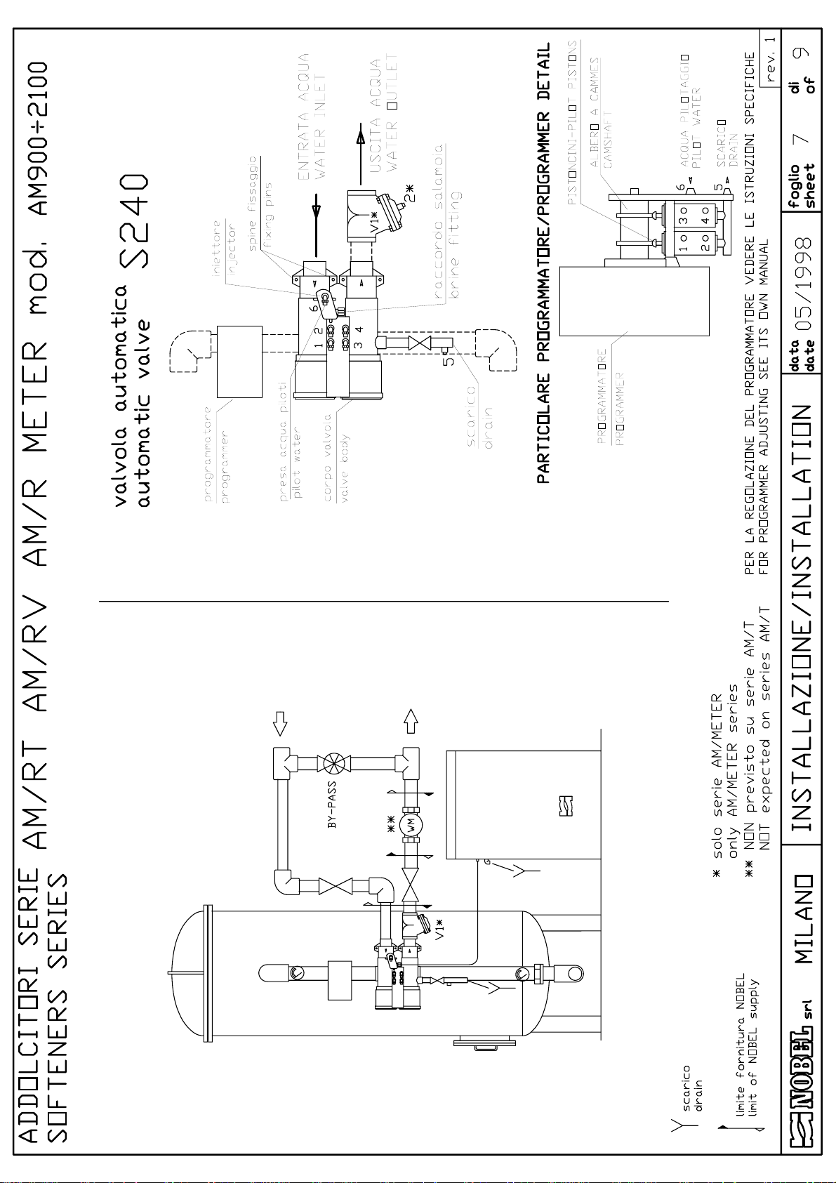
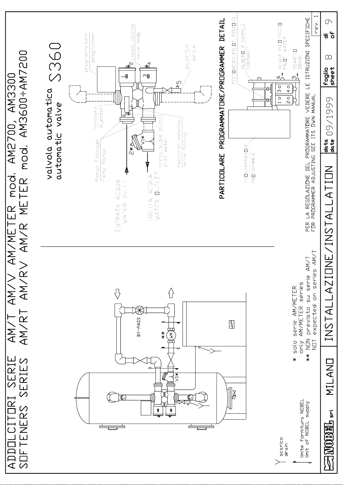
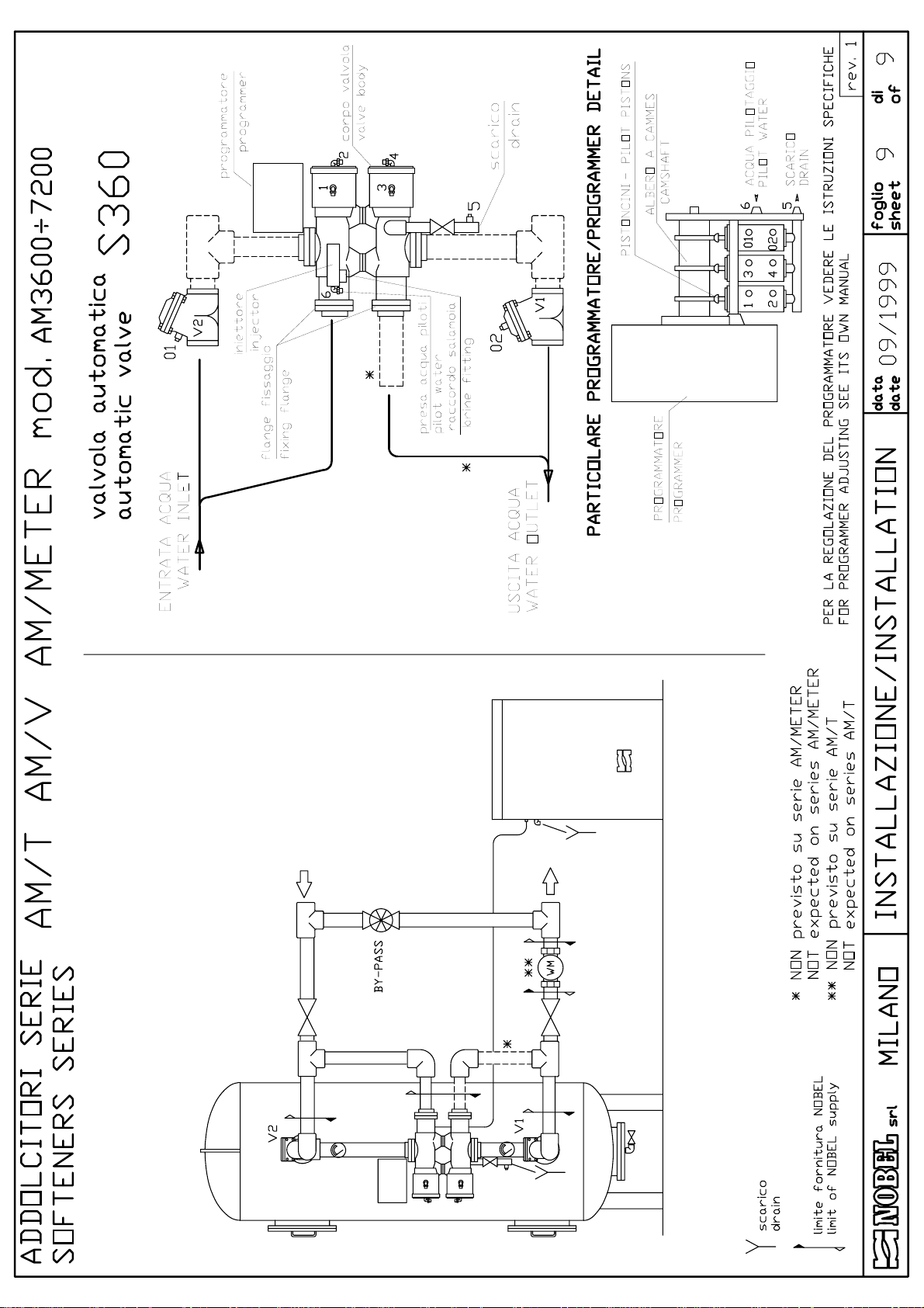
4.5. Hydraulic connections .........................................................................................................8
4.6. Electrical wiring connections ...............................................................................................8
5. End cycle and regeneration......................................................................................................9
5.1. End cycle.............................................................................................................................9
5.2. How to select the end-cycle ................................................................................................9
5.3. Regeneration.....................................................................................................................10
6. Starting-up ..............................................................................................................................11
7. Service & maintenance...........................................................................................................12
7.1. Disposal ............................................................................................................................12
8. Main components ...................................................................................................................13
8.1. Programmers ....................................................................................................................13
9. Trouble shooting guide ...........................................................................................................14
Annex:
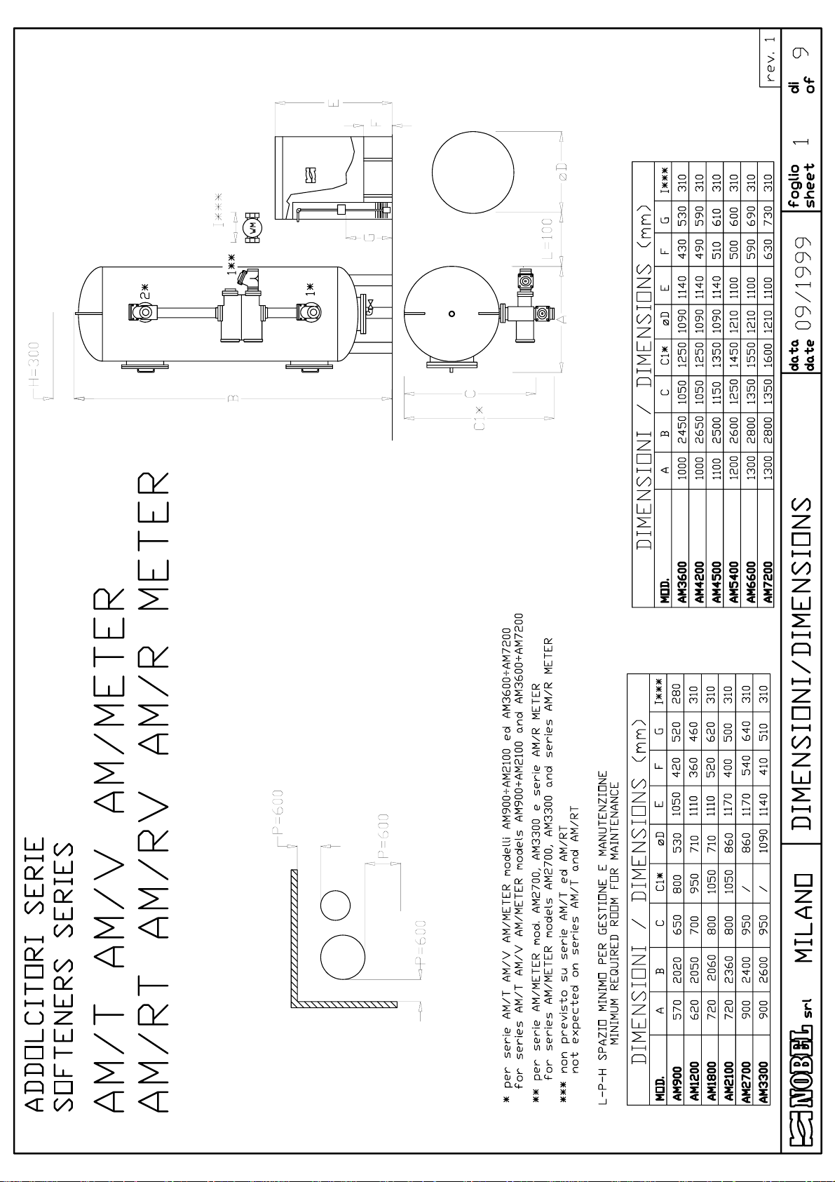
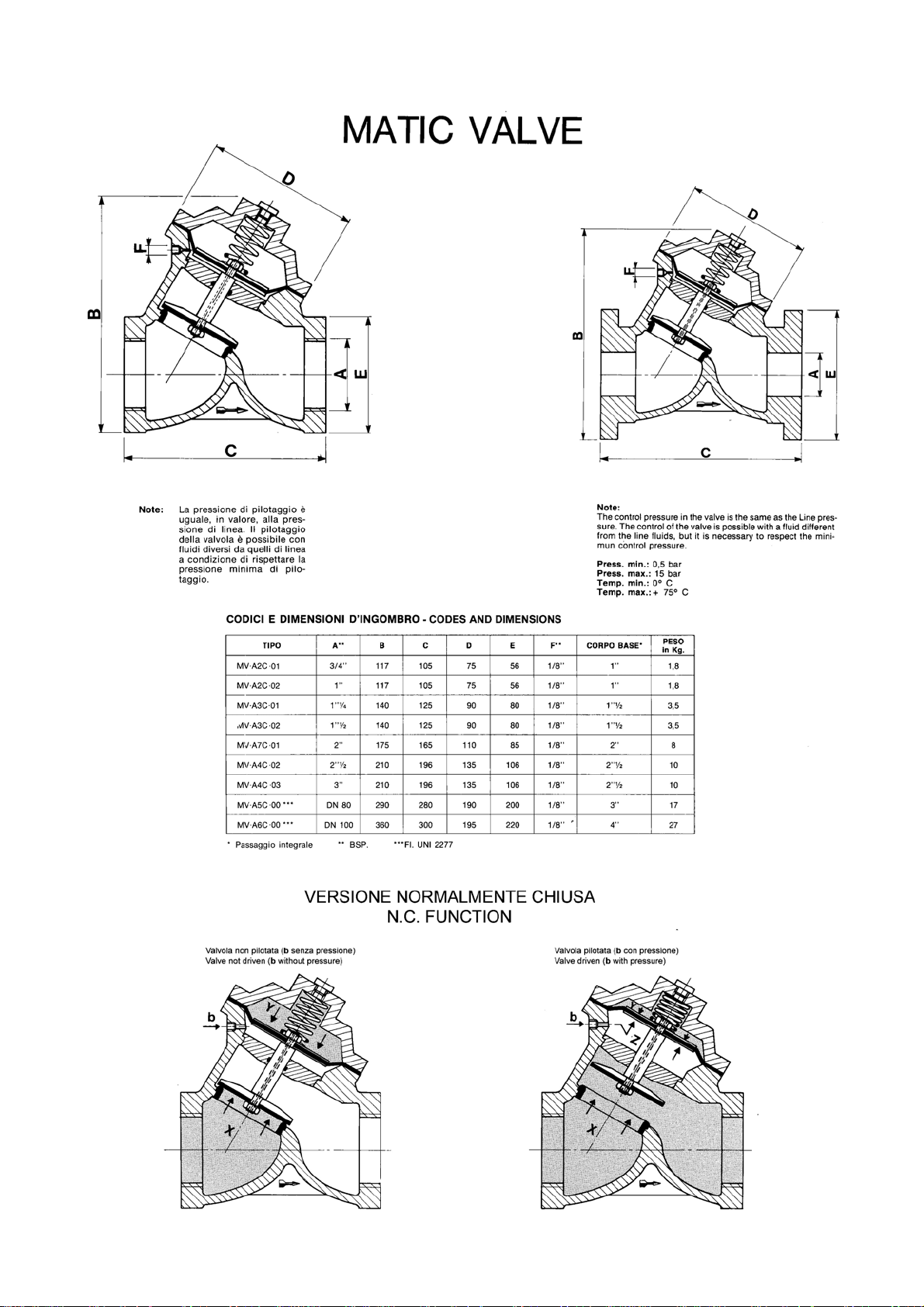
• DRAWING 1: dimensions AM/T AM/V AM/METER AM/RT AM/RV AM/RMETER
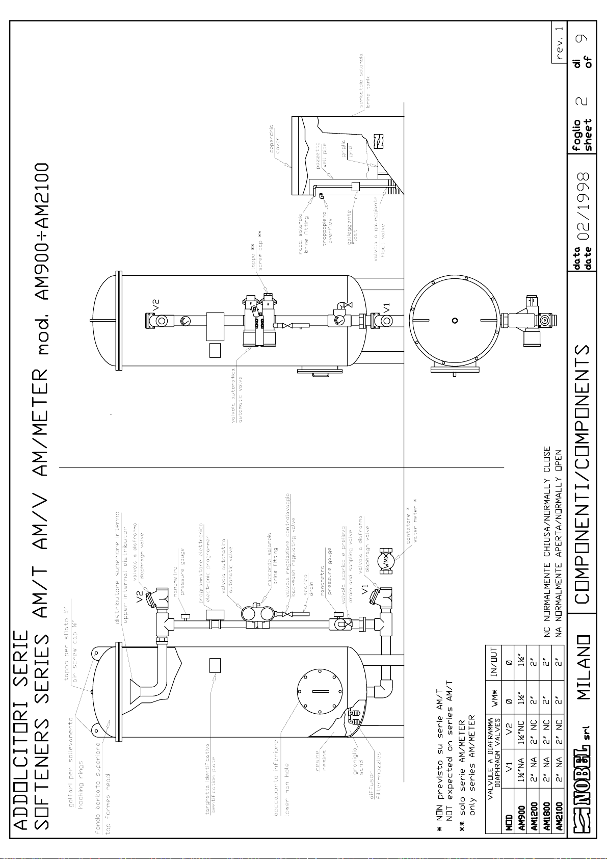
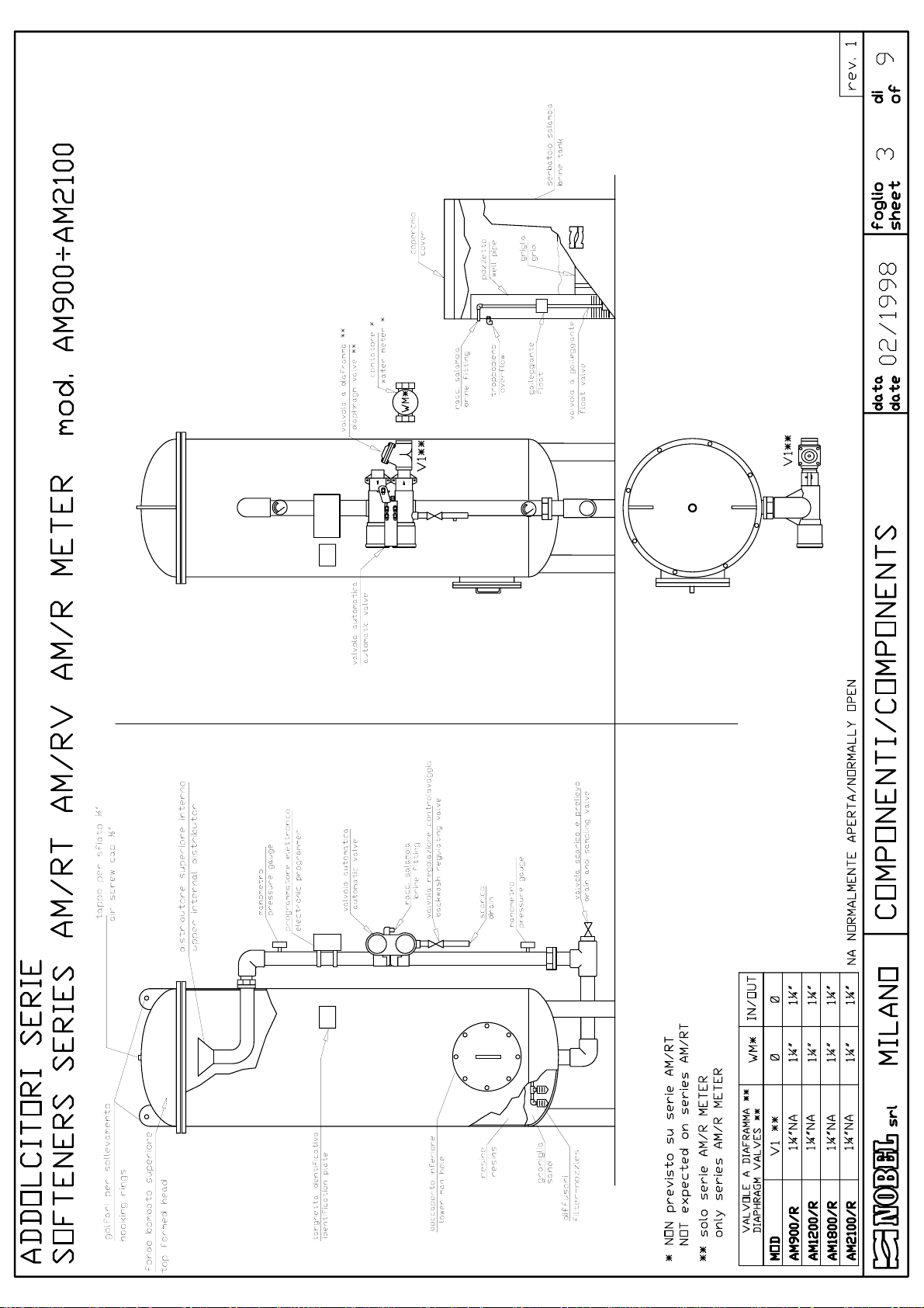
• DRAWING 2: components AM/T AM/V AM/METER models 900÷2100
• DRAWING 3: components AM/RT AM/RV AM/RMETER models 900÷2100
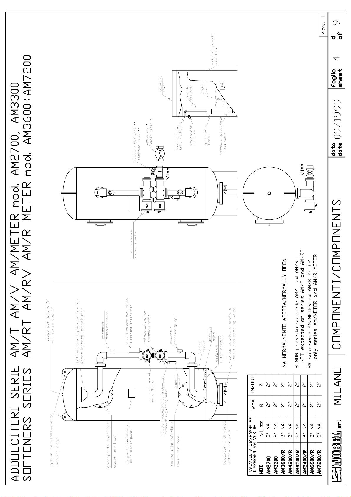
• DRAWING 4: components AM/T AM/V AM/METER models 2700, 3300 e AM/RT AM/RV
AM/RMETER models 3600÷7200
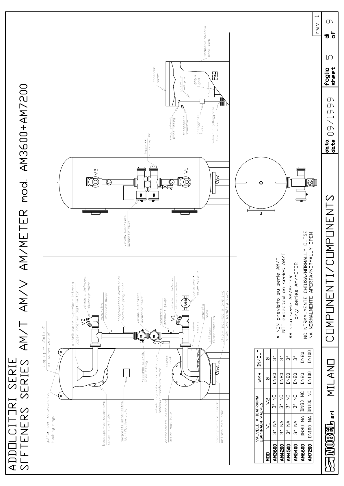
• DRAWING 5: components AM/T AM/V AM/METER models 3600÷7200
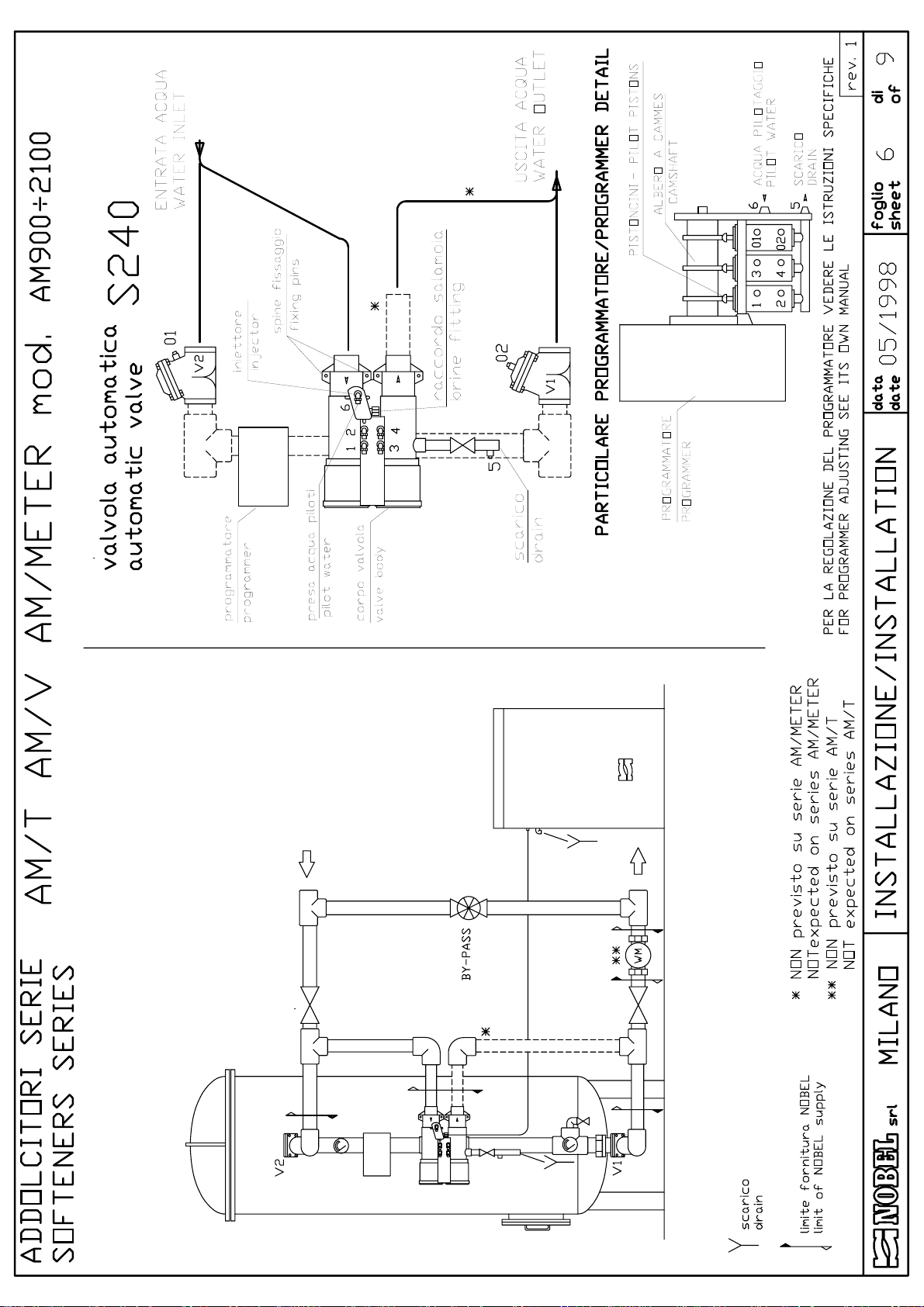
• DRAWING 6: installation AM/T AM/V AM/METER models 900÷2100
• DRAWING 7: installation AM/RT AM/RV AM/RMETER models 900÷2100
• DRAWING 8: installation AM/T AM/V AM/METER models 2700, 3300 e AM/RT AM/RV
AM/RMETER models 3600÷7200
• DRAWING 9: installation AM/T AM/V AM/METER models 3600÷7200
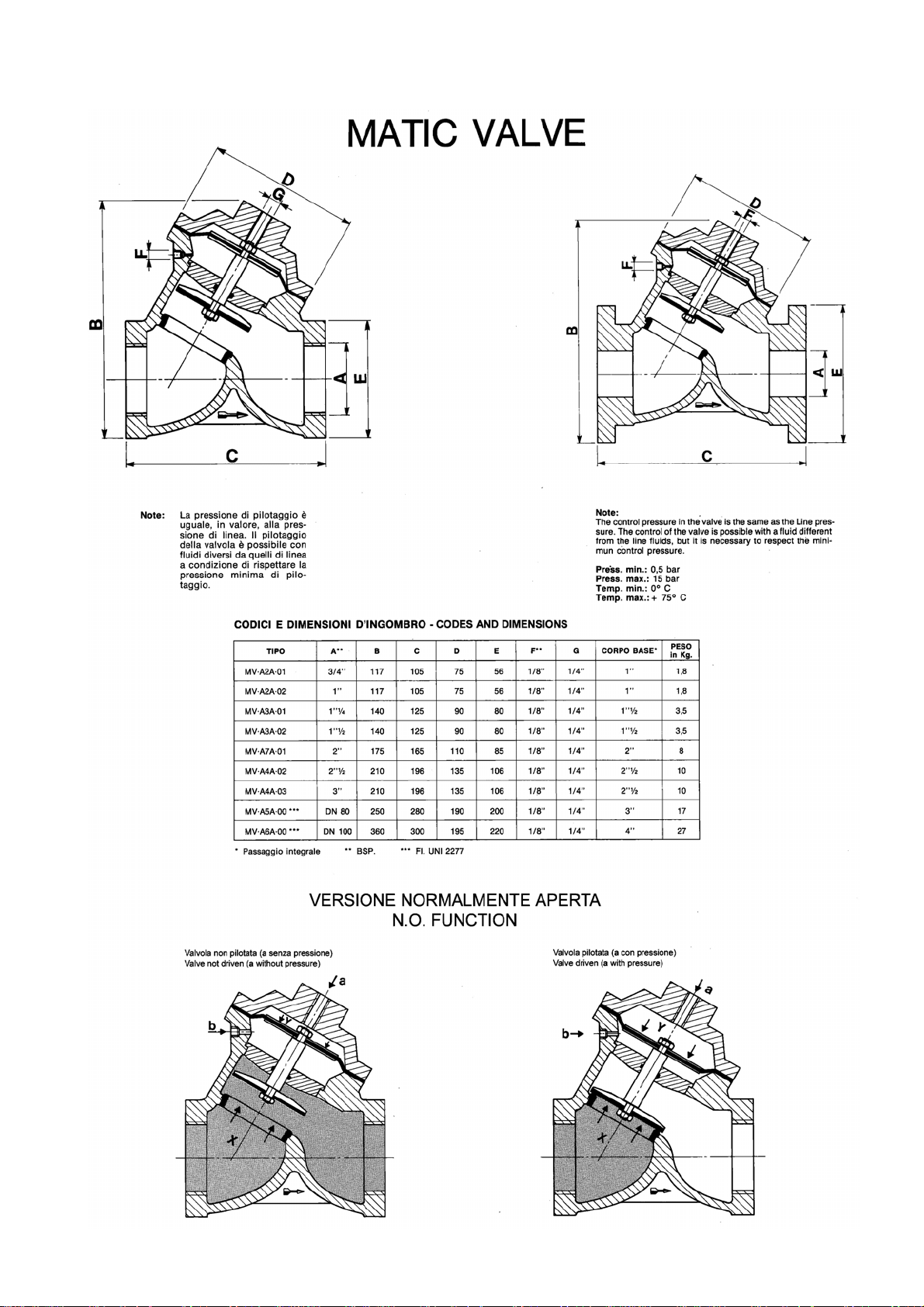
• Membrane valves special instructions
• Programmer special instructions
• Declaration of conformity
s.r.l. - ITALY Page 2 of 15 am_tvm_mi-r1.doc - r.1
Page 3

AUTOMATIC SOFTENERS INSTRUCTIONS MANUAL
AM/T AM/RT AM/V AM/RV AM/METER AM/R METER
1. Safety
1.1. CE mark, declaration of conformity
The equipment is designed to meet state-of-the-art safety requirements, has been tested and
left the factory in a condition in which it is safe to operate.
The equipment complies with the applicable standards and regulations as listed in the CE
declaration of conformity and thus complies with the statutory requirements of the CE
Directives.
NOBEL confirms the successful testing of the equipment by sticking to it the CE mark.
1.2. How to displace the unit
Particular care and attention should be put in during moving and displacing of heavy items, in
order to avoid injuries to persons or damage properties. (see § 3.5 page 6). The heavy parts
must be lifted and displaced always hooking and lifting them by the points shown on the
drawings (see fig. 1) and using only suitable ropes, hooks and/or chains, according to the
weight (see weight table).
1.3. Hydraulics
All operations must be performed by and/or under direct supervision of skilled and authorized
operators, using proper tools and personal protection devices if required (CE marked).
Before any operation of taking out pipes or part of hydraulic system, it is required to release
the pressure inside and empty the part of the system.
1.4. Electrical
Before starting any operation on electrical devices, be sure that main power supply is OFF.
All operations must be performed by skilled and authorized operators.
In case of liquid leakage, switch off the main power supply before operate. Before the
switching ON, be sure all the parts of the system are perfectly dry. Check that the available
electrical power is correct, (see § 3.2 page 5) before connection. Do not make preliminary wiring
connections.
1.5. How to store and delivery
• closed rooms
• open space
• transport
= ºC
5÷45 41÷113 5÷95%
5÷45 41÷113 5÷95%
5÷45 41÷113 5÷95%
= ºF humidity rel. notes
without condensate
without condensate
without condensate
protect from sun-light and rain.
protect from sun-light and rain.
s.r.l. - ITALY Page 3 of 15 am_tvm_mi-r1.doc - r.1
Page 4

AUTOMATIC SOFTENERS INSTRUCTIONS MANUAL
AM/T AM/RT AM/V AM/RV AM/METER AM/R METER
2. Principles of working
Softening is the process that allows to remove calcium and magnesium from water. These
two elements, together with bicarbonate, are the main cause of the scale inside thermal plant
and domestic appliances (heating system, laundry machines, etc.). They also can cause big
trouble in many industrial process.
The process of softening is featured by ion exchange. The resins contained in the column
exchange the ions calcium and magnesium (Ca
they are charged. When the resins are exhausted, they are fully charged of calcium and
magnesium (Ca
++
e Mg++) while they do not have any more sodium ions (Na+) available for
exchanging and they need to be regenerated.
Regeneration means re-built the charge of sodium ions (Na
(NaCl), common salt used in kitchen. During regeneration, an exchanging back is performed of
sodium ions (Na
+
) against ions calcium and magnesium (Ca++ e Mg++) which are carried away
to drain. The equipment prepares automatically the brine from the salt (NaCl) in grain or tablets.
AM series softeners are used for water treatment for residential and industrial applications as
well. All the materials, resins included, are food grade and approved for drinking water.
The range of models includes systems with capacity from 5 up to 60 m³/h and capacity from
900 up to 7200 m³ x ºF.
The working of the system is controlled by an automatic programmer, allowing to schedule
the frequency and the hour for the regeneration. Then the system automatically starts the
regeneration that proceed automatically. During regeneration, (except for "fast rinse" phase) the
system supplies non softened water thanks to a by-pass inside the automatic valve; for
AM/METER models, water supply during regeneration is completely inhibited by means of a
membrane valve mounted on the outlet.
These system can be equipped with automatic sterilizing device (Nobel CL 90 or CL 180),
according to the local laws of some countries for the treatment of drinking water.
++
and Mg++) against sodium ions (Na+), of which
+
) available from sodium chloride
s.r.l. - ITALY Page 4 of 15 am_tvm_mi-r1.doc - r.1
Page 5

3. Technical characteristics
3.1. Assumed raw water characteristics
AUTOMATIC SOFTENERS INSTRUCTIONS MANUAL
AM/T AM/RT AM/V AM/RV AM/METER AM/R METER
• organics
• water temperature (min÷max)
• water pressure (min÷max)
NIL
ºC (ºF) 5÷40 (41÷104)
bar (kPa) 2÷6 (200÷600)
3.2. Technical characteristics (general)
• hardness of treated water (with raw water up to 30°Fr)
• power supply
• regeneration time
ºFr < 0.5
V ph/Hz W 230 1/50 10
min. 40÷70
3.3. Characteristics for each model
MODEL
AM 900
AM 900
AM 1200
AM 1200
AM 1800
AM 1800
AM 2100
AM 2100
AM 2700
AM 3300
AM 3600
AM 3600
AM 4200
AM 4200
AM 4500
AM 4500
AM 5400
AM 5400
AM 6600
AM 6600
AM 7200
AM 7200
IN/OUT drain brine m³/h m³ x ºFr
/R
/R
/R
/R
R
/R
/R
/R
/R
DN80 1¼" ¾" 48.0 6600 1000 165 8800
/R
DN100 1¼" ¾" 60.0 7200 1000 180 9600
The above data are used also for series: AM/T, AM/RT, AM/V, AM/RV, AM/METER, AM/R METER
connections flow max cycle brine tank capacity consumption for
l tot ≅ kg sale
1¼" 1" 9.5
1½" 1" 9.5
1¼" 1" 9.5
2" 1" 9.5
1¼" 1" 9.5
2" 1" 9.5
1¼" 1" 9.5
2" 1" 9.5
2" 1¼" ¾" 18.0 2700 520 67.5 3600
2" 1¼" ¾" 22.0 3300 850 82.5 4400
2" 1¼" ¾" 22.0 3600 850 90 4800
3" 1¼" ¾" 28.0 3600 850 90 4800
2" 1¼" ¾" 22.0 4200 850 105 5600
3" 1¼" ¾" 28.0 4200 850 105 5600
2" 1¼" ¾" 22.0 4500 850 113 6000
3" 1¼" ¾" 32.0 4500 850 113 6000
2" 1¼" ¾" 22.0 5400 1000 135 7200
3" 1¼" ¾" 36.0 5400 1000 135 7200
2" 1¼" ¾" 22.0 6600 1000 165 8800
2" 1¼" ¾" 22.0 7200 1000 180 9600
mm 5,5 900 200 22.5 1200
mm 8,0 900 200 22.5 1200
mm 5,5 1200 300 30.0 1600
mm 10,5 1200 300 30.0 1600
mm 5,5 1800 300 45.0 2400
mm 14,5 1800 300 45.0 2400
mm 5,5 2100 520 52.5 2800
mm 14,5 2100 520 52.5 2800
regeneration
salt kg water l
s.r.l. - ITALY Page 5 of 15 am_tvm_mi-r1.doc - r.1
Page 6
AUTOMATIC SOFTENERS INSTRUCTIONS MANUAL
AM/T AM/RT AM/V AM/RV AM/METER AM/R METER
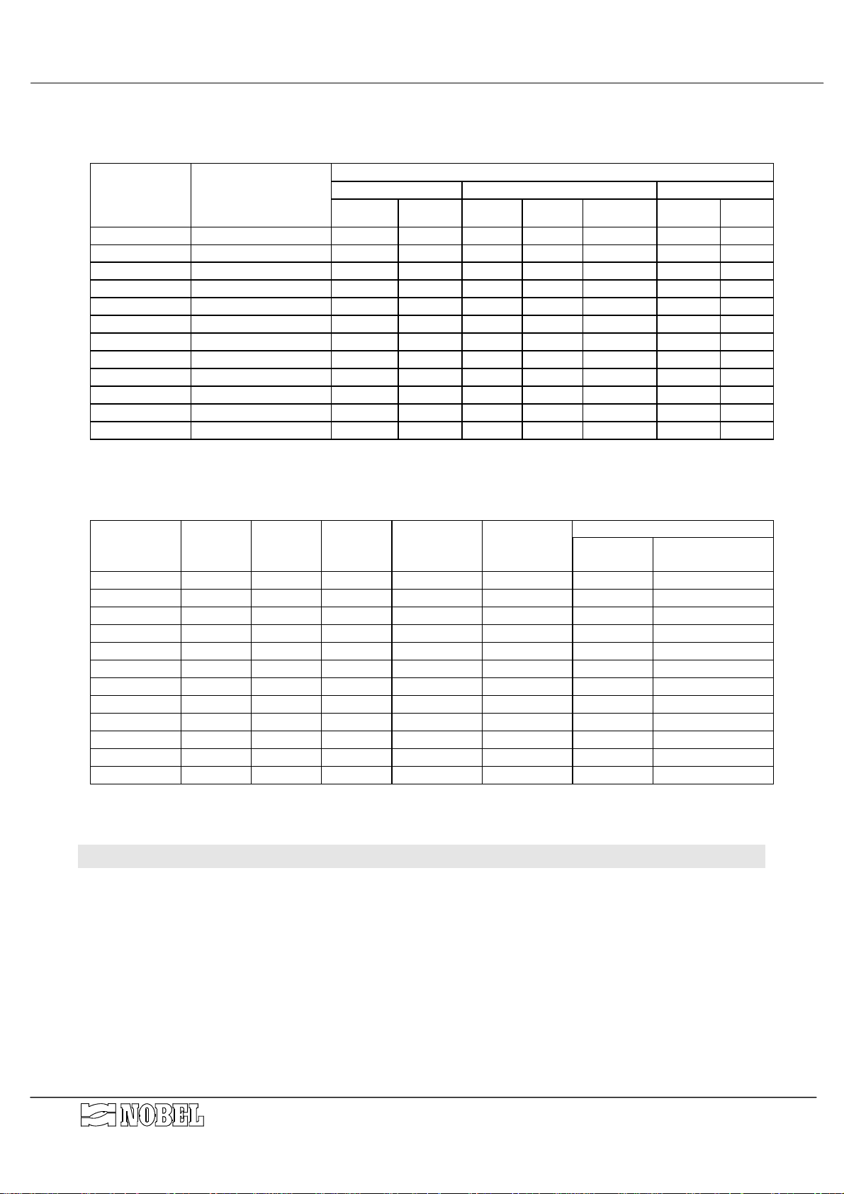
3.4. Dimensions
(See DRAWING 1 dimensions )
DIMENSIONS
MODEL overall vessels brine tank float valve
AM 900
AM 1200
AM 1800
AM 2100
AM 2700
AM 3300
AM 3600
AM 4200
AM 4500
AM 5400
AM 6600
AM 7200
l x p x h mm
1300x800x2100 2100 450 600 1100 420 3/8" 520
1450x900x2100 2100 500 700 1100 360 3/8" 460
1500x1100x2100 2100 600 700 1100 520 3/8" 620
1600x1100x2400 2400 600 800 1100 400 3/8" 500
1700x1050x2400 2400 700 800 1100 540 ¾" 640
1900x1050x2600 2600 700 1000 1100 410 ¾" 510
1950x1350x2400 2400 800 1000 1100 430 ¾" 530
1950x1350x2600 2600 800 1000 1100 490 ¾" 590
2050x1450x2400 2400 900 1000 1100 510 ¾" 610
2250x1550x2400 2400 1000 1100 1100 500 ¾" 600
2350x1700x2600 2600 1100 1100 1100 590 ¾" 690
2350x1750x2600 2600 1100 1100 1100 630 ¾" 730
h mm
Ø mm
Ø max
mm
h mm h plate mm type
The above data are used also for series AM/R
3.5. Weight
MODEL
AM 900
AM 1200
AM 1800
AM 2100
AM 2700
AM 3300
AM 3600
AM 4200
AM 4500
AM 5400
AM 6600
AM 7200
Vessel quartz-
sand
Kg kg
140 25 150 7 350 550 210
155 25 200 12 420 650 320
185 50 300 12 570 900 320
205 50 350 20 650 1050 550
305 50 450 20 850 1400 550
335 50 550 30 1000 1600 900
365 75 600 30 1100 1800 900
385 75 700 30 1200 2000 900
415 100 750 30 1300 2200 900
455 100 900 40 1500 2700 1050
625 100 1100 40 1900 3500 1050
625 100 1200 40 2000 3600 1050
resins brine tank total at
l (≅ kg)
The above data are used also for series AM/R
shipping
kg approx. kg approx. kg approx. kg
vessel fillled brine tank
on service
h mm
4. Installation
4.1. Room conditions
In cold countries, whether the room temperature is below 15 °C (59°F), the salt requires
longer time to be dissolved, even up to 10 hours; this feature must be considered in designing
and selecting the correct system. Apply Nobel Technical Dept. for further information.
• room temperature
• humidity rel.
• sun-light
• rain, snow etc.
s.r.l. - ITALY Page 6 of 15 am_tvm_mi-r1.doc - r.1
5÷45ºC (41÷113ºF)
5÷95 % without condensate
protection required
protection required
Page 7
AUTOMATIC SOFTENERS INSTRUCTIONS MANUAL
AM/T AM/RT AM/V AM/RV AM/METER AM/R METER
4.2. How to remove packaging
The vessels are shipped wrapped in a plastic foil; remove it with care before starting-up. The
automatic valves and pulse sender water meter (if present) are packed in a wooden crate.
Withdraw carefully the components from the crate. The resins are shipped in bags of 25 l each,
and the quartz-sand in bag of 50 kg or fraction of it. Keep the cards and everything contained
inside the packaging.
4.3. How to move and lift the unit
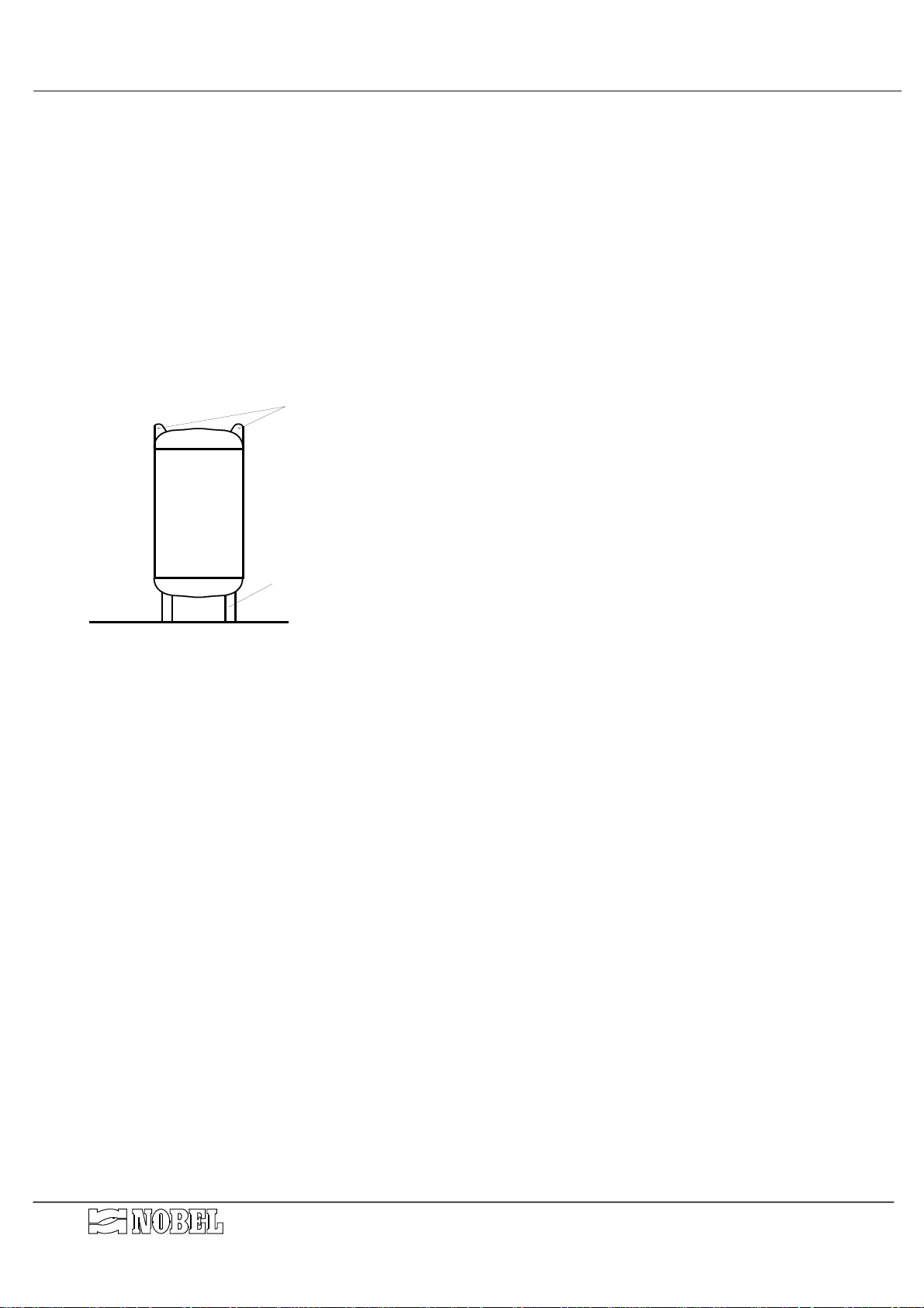
The vessels can be displaced when they are empty, hooking and lifting by the special rings
mounted on the upper part of the vessels (see fig. 1). It is recommended to use proper sized
hooks and ropes, according to the weight. It is also possible to hook and lift the vessel by the
bearing legs.
GOLFARI
CAUTION : DO NOT LIFT OR MOVE THE UNIT HOOKING OR
CATCHING BY THE PRE-ASSEMBLED PARTS .
GAMBE DI SOSTEGNO
Figure A
4.4. Placing & commissioning
• Place the column of resins and the brine tank on a perfectly flat surface. Their mutual
position is shown on the installation drawing. The shown scheme is only suggested; the
column can be placed in different positions; according to the inlet/outlet connections on the
valve group.
• Load the supplied quartz-sand into the vessel, through the lower man-hole, until the sand
covers completely the filter-nozzles. Make a flat surface of the sand using a wooden tool, in
order to avoid any damage to the coating of the vessel. Close the man-hole tightening the
nuts.
• Load the supplied resins into the vessel, through the upper man-hole (or through the upper
head, see components drawing). The resins are shipped separately; check that the shipped
and available quantity complies exactly with the quantity listed in the Weight Table § 3.5
page 6).
• After completed the loading, close the upper man-hole (or upper head)
• Fix the group of the regeneration valve to the resins vessel. The valves group includes also
the programmer.
• For models AM/R METER, AM2700/METER and AM3300/METER : connect the pre-
assembled piece fitting/membrane valve on the outlet connection of the regeneration valve.
NB :
The fittings of control valve type S240 have to be inserted just pushing them inside the
connections of body valve and then fixed with proper pins. The fittings of valves type S360
are flanged type with 4 fixing bolts.
s.r.l. - ITALY Page 7 of 15 am_tvm_mi-r1.doc - r.1
Page 8

AUTOMATIC SOFTENERS INSTRUCTIONS MANUAL
AM/T AM/RT AM/V AM/RV AM/METER AM/R METER
4.5. Hydraulic connections
(see installation and components drawings)
In order to avoid shut-off during maintenance operations, an emergency by-pass line
should be provided
• Connection of inlet fittings
For models AM/R, AM2700 and AM3300 only:
complete the line from the untreated water line
to the outlet fitting of the regeneration valve.
For all other AM models:
complete the line from the untreated water line to the outlet fitting of
the regeneration valve; connect also the inlet membrane valve V2 to the same water line.
• Connection of outlet fittings :
SERIES /T and /V, models AM/R, AM2700 and AM3300 only:
complete the line of the treated
water line to the inlet fitting of the regeneration valve.
SERIES /T and /V, all other AM models:
complete the line of the treated water line to the inlet
fitting of the regeneration valve; connect also the outlet membrane valve V1 to the same
water line.
SERIES METER:
For models AM/R, AM2700 and AM3300 only
complete the line of the treated water line to the outlet membrane valve V1.
the outlet membrane valve is installed
immediately downstream of the outlet fitting of the regeneration valve.
For all other AM models
the outlet membrane valve is plumbed at the bottom side of the resins
columns and the outlet fitting of regeneration line is plugged.
• Insert horizontally the pulse sender water meter downstream of outlet connections, (only for
series AM/V, AM/RV, AM/METER and AM/R METER).
• Connect the drain fitting placed on the side of the automatic valve to a floor drain. The gate
valve mounted on the drain fitting will be used to adjust the backwash flow rate.
A common flexible pipe made in plastic or rubber can be used for the drain line downstream
of the gate valve; its size must be equal or larger of the one mentioned on
“CHARACTERISTICS FOR EACH MODEL” table.
It is suggested that the drain line could be inspected in order to check quantity and quality of
drain water, as well as any leakage of resins from the unit.
CAUTION : Do not run the drain line together with overflow line of the brine tank; it will cause
the filling of the brine tank.
• Connect the over-flow fitting of the brine tank to a floor drain, with a line separated from the
drain lines of the vessels. Use proper sized flexible plastic or PVC pipe.
• Complete the line from the brine drawing fitting (on the side of the automatic valve) to the
float valve of the brine tank. For models up to AM 2100, use for the connection the supplied
plastic tubing ø 9.5 (mm); for models AM 2700 and over use ¾" galvanized pipe, or proper
sized PVC or plastic tubing, suitable to withstand the pressure and depressure (0.5 bar
negative).
• run the plastic tubes, already connected to the electronic programmer, to the fittings placed
on the control valves and on the diaphragm valves, according to the numbered sketch.
CAUTION : to avoid any damage of the plastic fittings and parts, it is required to hold all the
piping using adequately sized brackets.
4.6. Electrical wiring connections
• Connect the power feeder of the programmer to a power socket; check that the available
power is correct as listed in technical characteristics (see § 3.2 page 5).
• Connect the DIN plug from the water meter on the socket placed on the side of the
electronic programmer (only for series AM/V, AM/RV, AM/METER and AM/R METER).
s.r.l. - ITALY Page 8 of 15 am_tvm_mi-r1.doc - r.1
Page 9
AUTOMATIC SOFTENERS INSTRUCTIONS MANUAL
f
AM/T AM/RT AM/V AM/RV AM/METER AM/R METER
5. End cycle and regeneration
5.1. End cycle
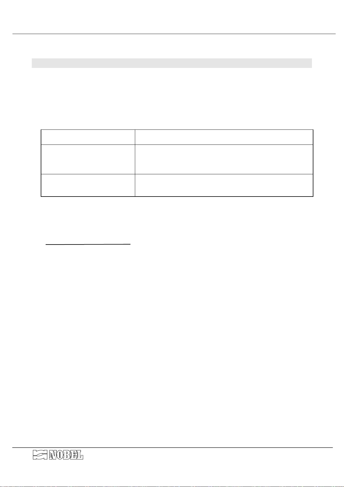
The softeners are equipped with an electronic programmer that allows to schedule the
automatic regeneration. The automatic start of regeneration depends on the type of
programmer that equips the unit, as follows :
• AM/T and AM/RT SERIES :
• AM/V and AM/RV SERIES :
• AM/METER and
AM/RMETER SERIES :
The end-cycle has to be adjusted according to the quality of available water and the
consumption of water.
The max. quantity of available soft water the equipment can supply between two following
regeneration is to be calculated as follows:
cycle of the softener (m³
=
total hardness o
raw water (°Fr)
∗
ºFr)
where 1°Fr = 10 ppm CaCO
The cycle of all NOBEL softeners are expressed by the number identifying the model (i.e.
AM 2700/D, the cycle is 2700 m
The regeneration can also be started manually at any time (see instruction of the
programmer).
electronic time programmer : selected time and day (24 h, 14
days, max 1 regeneration per day)
end-cycle by time/volume (pulse sender external to the
automatic valve); regeneration runs at selected time and day
(24 h, 14 gg, max 1 regeneration per day), or after the preset
volume of water has been supplied but only at a pre-set time.
end-cycle by volume; regeneration runs after the preset
volume of water has been supplied, with membrane valve to
shut off the flow during regeneration
m³ of available soft water per cycle
= 0.56° German
3
3
x °Fr)
5.2. How to select the end-cycle
The programmer installed on the AS/V and AS/METER series allows also working mode time
only, besides volume only and time/volume modes.
Whether it is desired to use the equipment with working mode different than the standard
one, it is possible to select an end-cycle mode different than the pre-set one; it is required to
select the new mode, according to the explanation in the special instruction of the programmer
(mod. AQUA TIMER).
s.r.l. - ITALY Page 9 of 15 am_tvm_mi-r1.doc - r.1
Page 10

AUTOMATIC SOFTENERS INSTRUCTIONS MANUAL
AM/T AM/RT AM/V AM/RV AM/METER AM/R METER
5.3. Regeneration
The regeneration phases run one after one, as follows :
1. backwashing: during this phase, the water flush from the bottom to the top of the column,
lifting the resins which are mixed together and release the solids trapped on surfaces of
the resins bed during the service. The backwashing water flows to drain from the top of
the column. This is the only phase, during which the water crosses through the column
from the bottom to the top. During this phase, it is very important to check that there is no
leakage of resins to the drain.
2. brine drawing: during this phase, a concentrated solution of water and sodium chloride
(common kitchen salt, in grain or, better, tablet) is drawn from the brine tank to the resins
column, by an injector. The brine crosses through the column from the top to the bottom.
3. slow rinse: it is the first step of the rinse, during which the ion exchanges between
sodium chloride and resins is featured. The time of this phase is not adjusted, since it
starts when the brine tank is completely empty (all brine has been drawn); a special
device built-in the brine float valve avoids the air drawing.
4. fast rinse: it is the phase during which the residual of salt is flushed away through the
resins; at the end of this phase the resins column is ready to start again a new service
cycle.
NOTE: During the fast rinse phase the unit supplies the water to the brine tank, in order to
prepare the brine for the following regeneration. The brine tank refill will be
automatically completed when the level mark of water reaches the float valve inside
the tank.
NOTE : During regeneration, (except for "fast rinse" phase) the system supplies non
softened water thanks to a by-pass inside the automatic valve; for AM/METER and
AM/RMETER series, water supply during regeneration is completely inhibited by
means of a membrane valve mounted on the outlet.
See programmer manual for the time of each phase of regeneration.
s.r.l. - ITALY Page 10 of 15 am_tvm_mi-r1.doc - r.1
Page 11

AUTOMATIC SOFTENERS INSTRUCTIONS MANUAL
AM/T AM/RT AM/V AM/RV AM/METER AM/R METER
6. Starting-up
The starting-up of the unit consists of running a first regeneration cycle, during which the
columns of resins and brine tank will be filled of water, all automatic features will be checked
and the unit will be prepared to start the service.
During the starting-up is not required that salt is available inside the brine tank.
At the end of the first regeneration, put the salt into the brine tank (it can also be completely
filled). Take care not to put salt inside the protection pipe.
See § 7 page 12 for recommended quality of salt to be used.
To start-up the unit, proceed as follows :
• Be sure that the control panel is switched OFF.
• Open the by-pass valve, keeping closed the shut-off valves upstream and downstream of the
system.
• Close only partially the gate valve on backwash drain line.
• Turn clockwise the cam shaft located on the back of the programmer, until the first piston is
pressed. The second piston must not be pressed (BACKWASH).
• Open slowly and not completely the inlet valve. Water will enter from the bottom of one of the
column as air will be expelled from the top to the drain.
• When only water will come out from the drain, open completely the inlet valve and open
slowly and gradually the backwash gate valve. The flow rate must be the highest allowable
without any leakage of resins through the drain line; so adjust the gate valve accordingly.
• When the proper flow rate of backwash has been stated, adjust the gate valve definitely.
• The backwashing phase must run until the water coming out the drain is perfectly clear.
• Using a pail, add water in the brine tank, until the water mark is approx. 30 cm (12 inches)
from the bottom (this is required for the initial regeneration only and is automatically filled
thereafter).
• Turn again clockwise the cam shaft, until both pistons are pressed (BRINE DRAWING AND
RINSE). Check that some water flows to the drain line, while, in the same time, the water
flows from the brine tank to the unit. Check the water mark diminution in the brine tank
(BRINE DRAWING).
• Turn again clockwise the cam shaft, until only the second piston is pressed. The first piston
must not be pressed (FAST RINSE). The water flows to the drain line; allow the water flowing
until the drain water looks perfectly clear. In the same time the water flows to the brine tank,
too, in order to prepare the brine for the following regeneration cycle. The water level inside
the brine tank is automatically adjusted according to the float valve.
• Turn clockwise the cam shaft, until both pistons are released and not pressed (SERVICE).
The 3
hydraulically the working of the inlet and outlet diaphragm valves of the column (if available); it
must be ignored.
• Switch ON the control panel.
• open the outlet valve and close the by-pass valve
• Put the salt into the brine tank (it can also be completely filled). Take care not to put salt
inside the protection pipe.
Starting now the unit is on service and feeds treated water.
rd
piston, available only for some kind of programmers, is used only to control
s.r.l. - ITALY Page 11 of 15 am_tvm_mi-r1.doc - r.1
Page 12

AUTOMATIC SOFTENERS INSTRUCTIONS MANUAL
AM/T AM/RT AM/V AM/RV AM/METER AM/R METER
7. Service & maintenance
Softeners are equipment designed to treat raw water supplied from municipalities or
from well.
ANY OTHER APPLICATIONS OF THE EQUIPMENT DIFFERENT THAN THE MENTIONED
ONES IS MADE UNDER THE ONLY RESPONSIBILITY OF THE USER.
The correct handling of the equipment requires:
• take off the raw water suspended solids, if any, by an adequate filtration.
• check that the water pressure is within the stated values.
• check the salt level in the brine tank. A salt lack will cause the incomplete regeneration of
the resins, or not any regeneration at all; in that case the supplied water will not be
treated (softened).
It is suggested to use clean salt, better in the shape of tablets, available almost everywhere,
in order to avoid residuals of sand or dirties in the tank and along the brine lines.
Not any further special maintenance operations are required.
The only consumption material is salt.
The average life of the ion exchange resins is approx. 5÷8 years, according to the quality of
raw water and how often regeneration is featured.
7.1. Disposal
In case of disposal of the unit or parts of it, it must be made according to local laws
concerning the waste of the materials. It should be taken in consideration that resins are usually
listed as plastic materials and not as toxic or harmful material (the safety bulletin of resins are
available upon request).
s.r.l. - ITALY Page 12 of 15 am_tvm_mi-r1.doc - r.1
Page 13
AUTOMATIC SOFTENERS INSTRUCTIONS MANUAL
8. Main components
Quantity DESCRIPTION
1 vessel in coated carbon steel (see table DIMENSIONS)
1 internal water distribution system (see following table)
1 automatic valve for regeneration
1 brine tank made in polyethylene c/w cover (see table DIMENSIONS)
1 separation plate for salt inside brine tank (see table DIMENSIONS)
1 float valve inside brine tank (see table DIMENSIONS)
# quartz-sand (see table WEIGHT)
# cation resins (see table WEIGHT)
# membrane valves made in cast-iron (see following table)
1* pulse sender water meter (see following table)
1 electronic programmer
# galvanized steel fittings several size
* NOT present for series AM/T and AM/RT
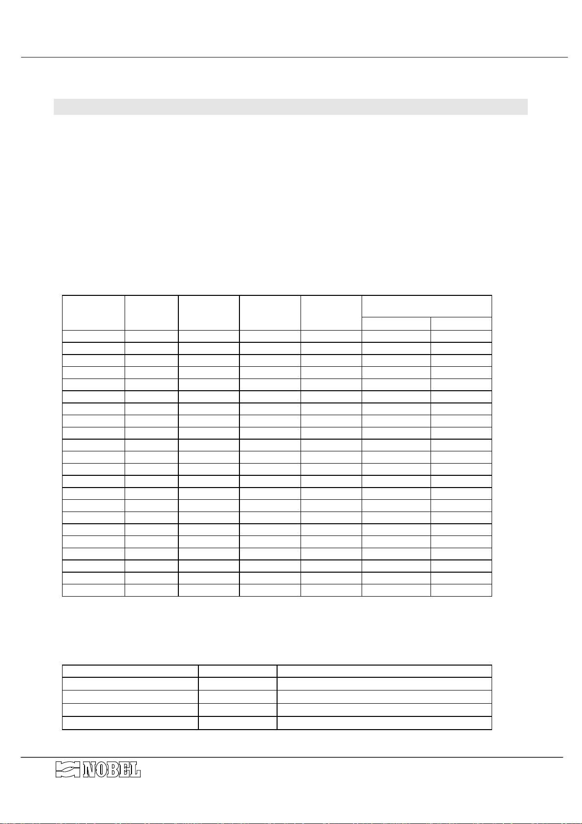
MODEL
AM 900/R
AM 900
AM 1200/R
AM 1200
AM 1800/R
AM 1800
AM 2100/R
AM 2100
AM 2700
AM 3300
AM 3600/R
AM 3600
AM 4200/R
AM 4200
AM 4500/R
AM 4500
AM 5400/R
AM 5400
AM 6600/R
AM 6600
AM 7200/R
AM 7200
water meter
Ø type number/type Øext. mm V1 V2
1¼" S240 6 x B144
1½" S240 6 x B144
1¼" S240 6 x B175
2" S240 6 x B175
1¼" S240 6 x B175
2" S240 6 x B175
1¼" S240 6 x B175
2" S240 6 x B175
2" S360 30 piastra
2" S360 30 piastra
2" S360 36 piastra
DN80 S360 36 piastra
2" S360 36 piastra
DN80 S360 36 piastra
2" S360 42 piastra
DN80 S360 42 piastra
2" S360 56 piastra
DN80 S360 56 piastra
2" S360 68 piastra
DN80 S360 68 piastra
2" S360 68 piastra
DN100 S360 68 piastra
* only for series AM/V AM/RV and AM/METER AM/R METER
** only for series AM/METER AM/R METER
automatic
valve
distribution
system
brine pipe
AM/T AM/RT AM/V AM/RV AM/METER AM/R METER
9.5
9.5
9.5
9.5
9.5
9.5
9.5
9.5
//
//
//
//
//
//
//
//
//
//
//
//
//
//
membrane valves
Ø and type
1¼" NA **
1½" NA 1½" NC
1¼" NA **
2" NA 2" NC
1¼" NA **
2" NA 2" NC
1¼" NA **
2" NA 2" NC
2" NA ** //
2" NA ** //
2" NA ** //
3" NA 3" NC
2" NA ** //
3" NA 3" NC
2" NA ** //
3" NA 3" NC
2" NA ** //
3" NA 3" NC
2" NA ** //
DN80 NA DN80 NC
2" NA ** //
DN100 NA DN100 NC
//
//
//
//
8.1. Programmers
PROGRAMMER TYPE SERIES MODELS
T 2 pilots T AM900÷7200/R - AM2700 - AM3300
T 3 pilots T AM900÷2100 – AM3600÷7200
AQUATIMER 2 pilots V - METER AM900÷7200/R - AM2700 - AM3300
AQUATIMER 3 pilots V - METER AM900÷2100 – AM3600÷7200
s.r.l. - ITALY Page 13 of 15 am_tvm_mi-r1.doc - r.1
Page 14
AM/T AM/RT AM/V AM/RV AM/METER AM/R METER
follows
programmer; enters again all programming
• connect electrical power
• replace the electrical feeder
• replace the programmer
• wait until regeneration is completed
AUTOMATIC SOFTENERS INSTRUCTIONS MANUAL
• make a short-circuit on the battery of the
data
• replace the programmer
• connect electrical power
• adjust correctly the programmer
• replace the programmer
electromagnetic interference from somewhere else.
• electrical power is disconnected
• the electrical feeder of the programmer is defected
• the programmer is defected
• a regeneration is running
• the electronic programmer has received
• the programmer is defected
• the programmer is not correctly adjusted
• the programmer is defected
• the geared motor of the programmer is defected • replace the geared motor of the programmer
programmer; enters again all programming
data
• make a short-circuit on the battery of the
electromagnetic interference from somewhere else.
separately to floor drain
• connect the drain line and over-flow line
• replace microswitch
• clean or replace float valve
over-flow line of brine tank
• the microswitch of the programmer is defected
• the drain line of the softener is joined together with
• brine float valve blocked or damaged
PROBLEM CAUSE HOW TO SOLVE
switch ON.
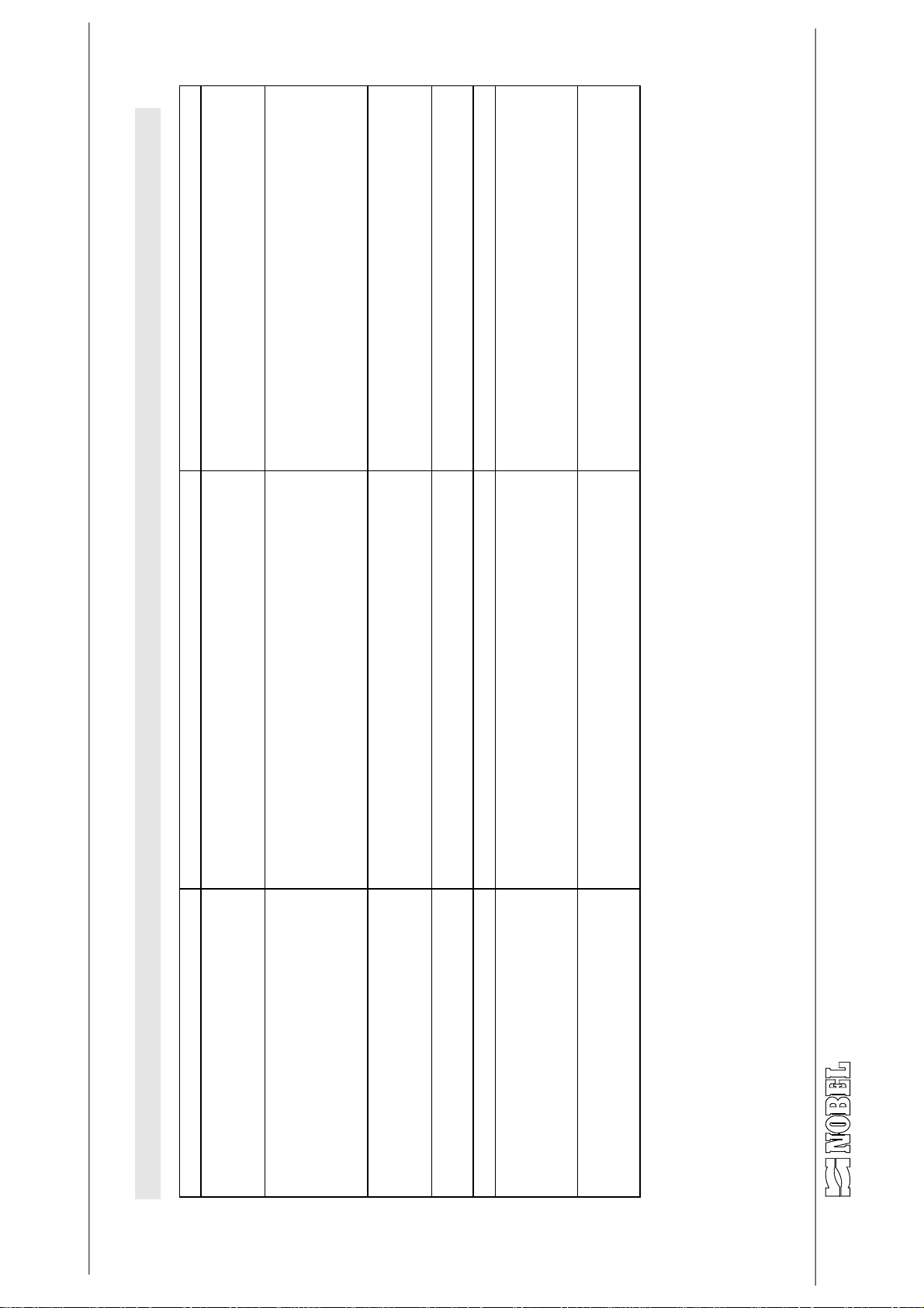
9. Trouble shooting guide
• The electronic programmer does not
programmer are on block
• The buttons of the electronic
but it does not run hydraulically
• The regeneration does not run • electrical power is disconnected
• Regeneration is electrically started
• Regeneration is on block • the geared motor of the programmer is defected • replace the geared motor of the programmer
• Regeneration never ends • the electronic programmer has received
water overflows
• Brine tank is completely filled and
s.r.l. - ITALY Page 14 of 15 am_tvm_mi-r1.doc - r.1
Page 15
AM/T AM/RT AM/V AM/RV AM/METER AM/R METER
• re-built correctly the drain line
AUTOMATIC SOFTENERS INSTRUCTIONS MANUAL
brine drawing tubing
• increase the water pressure
• check the connections and the integrity of the
• clean the injector
• clean the injector filter
• clean or replace the brine float valve
• clean or replace the pistons
• replace O-rings
• replace pistons
• replace pilot pistons
• see above
• see above
• run regeneration again
• replace resins
too small size
• drain line of the softener clogged or, however of
• too low water pressure
• drawing of air along the brine drawing line
• injector dirty
• filter of injector dirty
• brine float valve blocked or damaged
• internal pistons of the control valve blocked
• O-ring of internal pistons spoiled
• internal pistons spoiled
• pilot pistons spoiled or broken
• brine is not drawn
• a water failure occurred during regeneration
• resins spoiled
more
• allow the water flowing until it is not salted any
• replace the nozzle
• adjust a longer time of fast rinse
damaged or broken
• a water failure occurred during regeneration
• the fast rinse time is too short
• one (or more) filter nozzle of distribution system is
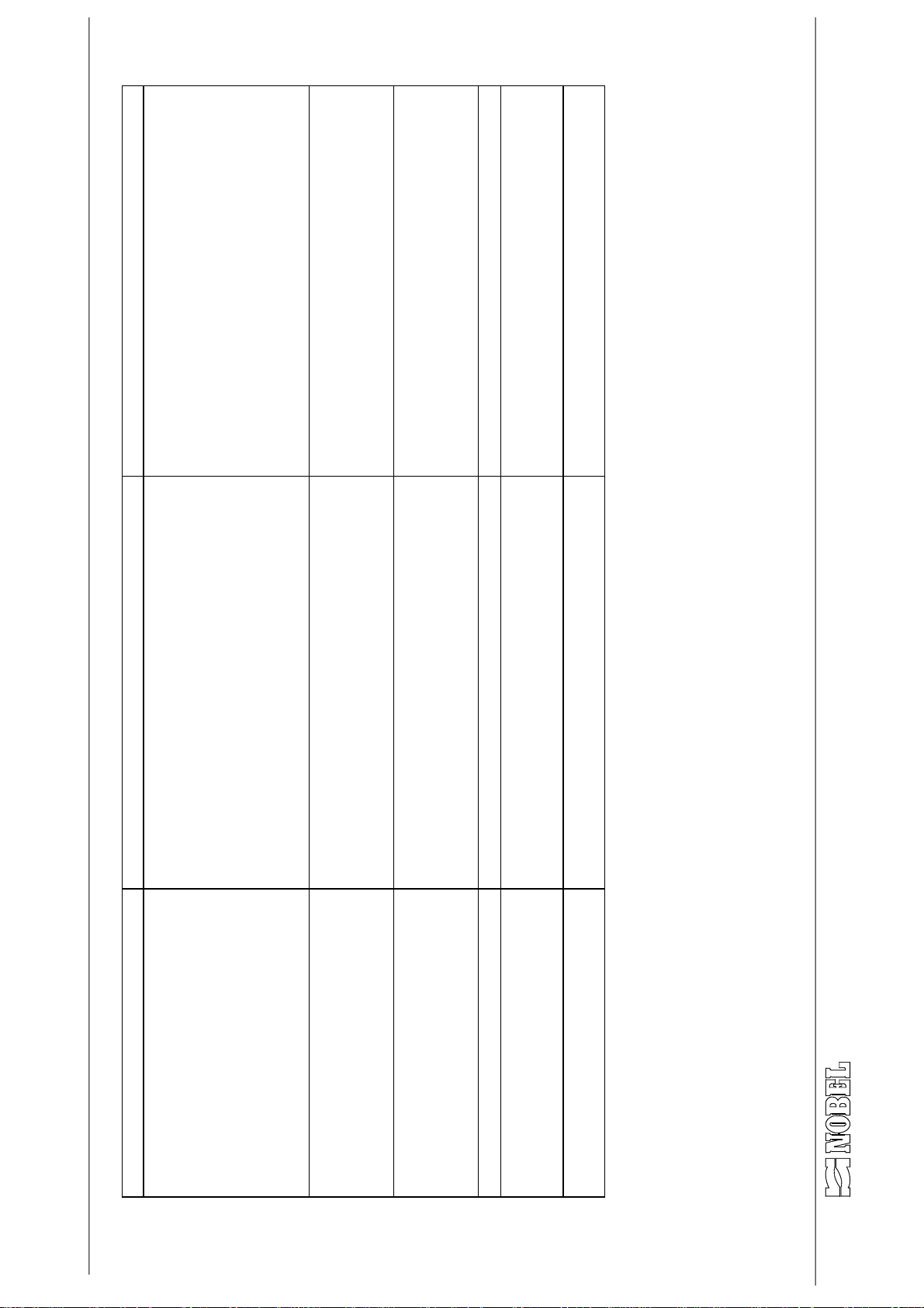
PROBLEM CAUSE HOW TO SOLVE
not draw brine
follows
• During regeneration the unit does
during service
• There is a leakage of water to drain
regeneration
• The unit does not feed treated water • regeneration does not run
• The unit does not feed water • pistons blocked during regeneration • clean or replace the pistons
• The unit feeds salted water after
• There is a leakage of resins to the
drain or to outlet line
s.r.l. - ITALY Page 15 of 15 am_tvm_mi-r1.doc - r.1
Page 16
Page 17
Page 18
Page 19
Page 20
Page 21
Page 22
Page 23
Page 24
Page 25
Page 26
Page 27

s.r.l.
via G.Galilei, 5 20090 Segrate (MI) - ITALY
società italiana per lo studio e la realizzazione di apparecchiature ed impianti per il trattamento acqua
engineering and manufacturing of equipments and plants for water treatment
AZIENDA CON SISTEMA
QUALITÁ CERTIFICATO DA DNV
UNI EN ISO 9001/2008
TEL. +39 02 2827968
FAX +39 02 2610839
e-mail [email protected]
www.nobelitaly.it
DICHIARAZIONE DI CONFORMITÀ
DECLARATION OF CONFORMITY
La Nobel srl dichiara che l’apparecchiatura (vedi etichetta in prima pagina)
delle serie
Nobel srl hereby declares that the equipment (see label on first page)
of series :
AM…/T /V /METER /V DUPLEX AM…/RT /RV /R METER /RV DUPLEX
è conforme alle seguenti Direttive Europee:
2006/42/CE – 2006/95/CE – 2004/108/CE
Principali Norme armonizzate osservate durante la progettazione e costruzione:
UNI EN ISO 12100:2010 – UNI EN 60204-1 (CEI 44-5)
Il direttore tecnico è autorizzato alla costituzione del fascicolo tecnico.
complies to the requirement of the following European Directives :
2006/42/CE – 2006/95/CE – 2004/108/CE
Besides, the main regulations followed for the design and manufacturing are :
UNI EN ISO 12100:2010 – UNI EN 60204-1 (CEI 44-5)
The technical manager is authorized to manage the technical folder.
Direttore Tecnico
Technical Manager
Giorgio Da Dalt
Milano, 6 marzo 2012
M3.6-r2
C.C.I.A.A. 1250687 - EXPORT MI 044905 - Reg. Trib. Milano nº 272528 vol.7032 fasc.28
sede legale : via Monfalcone 8 20132 Milano
società a responsabilità limitata - cap. soc. € 99.000 i.v. - C.F. e P.I. : IT 08829620155
rev. 1
 Loading...