

Page 1
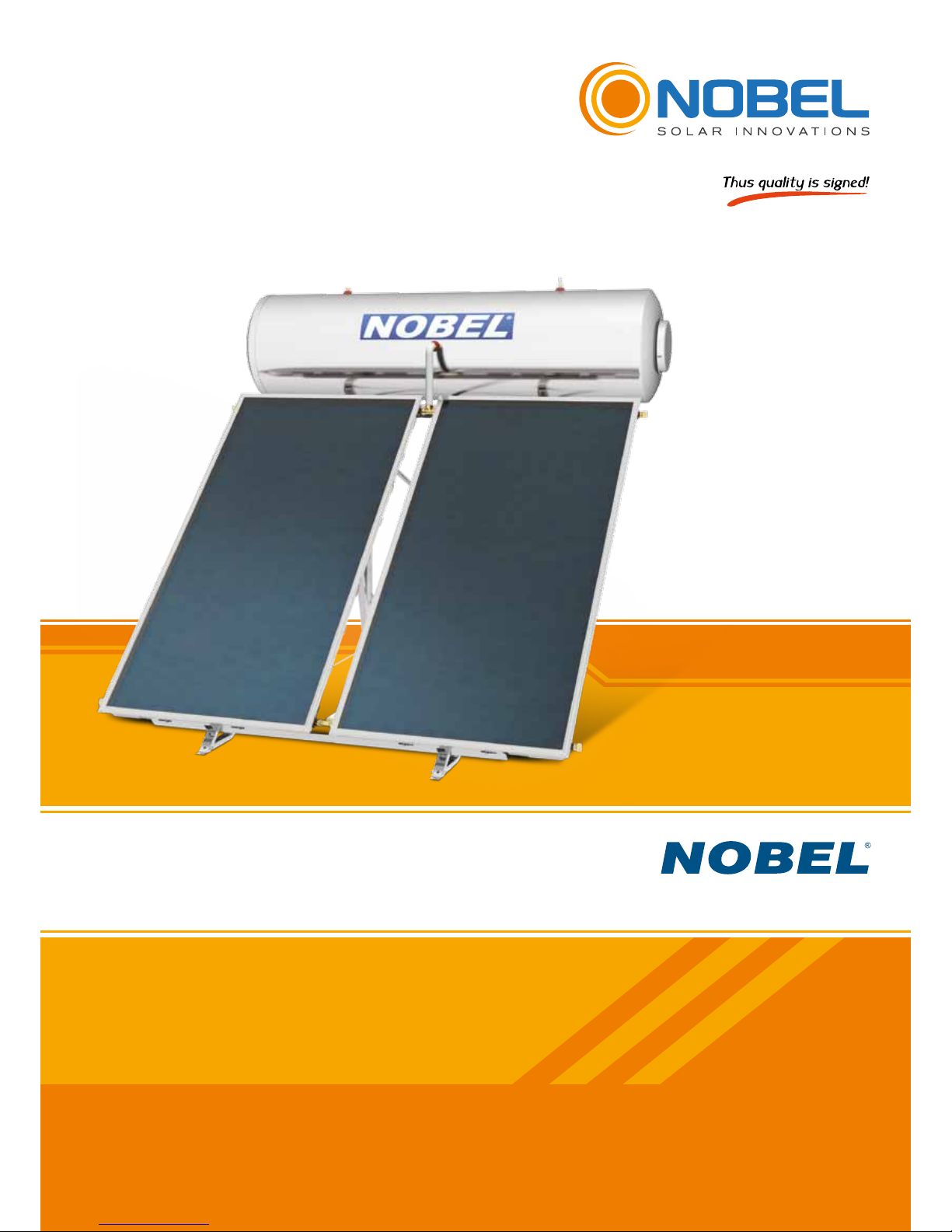
Solar water heaters
Installation, maintenance & use instructions
TECHNICAL MANUAL
Page 2

Page 3

3
CLASSIC
Nobel Xilinakis D. & Co preserves the right to change all specications of the products and their accessories without prior notice
CONTENTS
DOMESTIC HOT WATER CONSUMPTION ............................................................................................................... 4
SOLAR WATER HEATER OPERATION - WATER HEATING ..................................................................................... 4
SOLAR WATER HEATERS ......................................................................................................................................... 5
LABELING ................................................................................................................................................................... 5
PACKAGING ............................................................................................................................................................... 6
WATER STORAGE TANK SPECIFICATIONS ............................................................................................................ 7
COLLECTOR APOLLON AL SPECIFICATIONS ........................................................................................................ 8
SOLAR WATER HEATER 120lt/2m
2
LAYOUT .......................................................................................................... 10
SOLAR WATER HEATER 160lt/2m
2
LAYOUT .......................................................................................................... 11
SOLAR WATER HEATER 160lt/2.6m
2
LAYOUT ....................................................................................................... 12
SOLAR WATER HEATER 160lt/3m
2
LAYOUT .......................................................................................................... 13
SOLAR WATER HEATER 200lt/2.6m
2
LAYOUT ....................................................................................................... 14
SOLAR WATER HEATER 200lt/3m
2
LAYOUT .......................................................................................................... 15
SOLAR WATER HEATER 200lt/4m
2
LAYOUT .......................................................................................................... 16
SOLAR WATER HEATER 320lt/4m
2
LAYOUT .......................................................................................................... 17
GENERAL INSTALLATION RULES ..........................................................................................................................18
INSTALLATION POSITION ....................................................................................................................................... 19
GENERAL PREVENTION MEASURES .................................................................................................................... 20
SUPPORT BASE ASSEMBLY ON A FLAT SURFACE (System with 1 collector) ...................................................... 21
SUPPORT BASE ASSEMBLY ON FLAT SURFACE (System with 2 collectors) ....................................................... 24
SUPPORT BASE ASSEMBLY ON AN INCLINED SURFACE (System with 1 collector) ........................................... 27
SUPPORT BASE ASSEMBLY ON AN INCLINED SURFACE (System with 2 collectors) ......................................... 28
HYDRAULIC CONNECTION ..................................................................................................................................... 33
CLOSED LOOP FILLING .......................................................................................................................................... 33
ELECTRICAL CONNECTION ................................................................................................................................... 34
SYSTEM INSTALLATION ON A TILED ROOF WITH THE WATER STORAGE
TANK UNDER THE ROOF (NATURAL CIRCULATION OPERATION) ..................................................................... 35
CONNECTING THE HEAT CHARGER ..................................................................................................................... 35
POSSIBLE PROBLEMS - SOLUTIONS .................................................................................................................... 36
SERVICE - MAINTENANCE ..................................................................................................................................... 37
POST INSTALLATION INSTRUCTIONS ................................................................................................................... 38
CHECK LIST ............................................................................................................................................................. 39
METEOROLOGICAL DATA OF EUROPEAN CITIES ............................................................................................... 40
NOTES ...................................................................................................................................................................... 41
Page 4

4
Nobel Xilinakis D. & Co preserves the right to change all specications of the products and their accessories without prior notice
NOBEL, Xilinakis D. & Co Industry is active in the Solar Energy Field since 1975, always with high-tech equipment,
ultra-modern facilities and certied products of high quality. Our experience and know-how support our co operations,
before and after sales, both in Greece and abroad.
In the present manual you will nd all necessary instructions with regard to the installation, operation and
maintenance of NOBEL Solar Water Heaters.
Nowadays, the necessity for production and saving of energy without at the same time polluting the
environment has become common knowledge. The planet’s conventional energy resources are diminishing to a
threatening level as our society’s energy requirements are increasing, generating pollutants that affect the climate’s
balance.
Renewable energy sources promise a solution to the energy problem as well as to pollution. Gradually, the
international legislation is changing and encouraging - or even imposing - the use of alternative energy products, with
the aim to satisfy energy requirements without endangering the environment.
DOMESTIC HOT WATER CONSUMPTION
Statistically, it is estimated that the mean family consumption is 35 to 50 litres daily per person. If we add the
consumption of a washing machine and a dishwasher, when these are connected to the solar water storage tank,
then each requires 20 litres per day (per wash).
Thus, a family of four, for example, with a mean hot water consumption of 40 litres per person, needs an 160
litres solar water heater. If household appliances connected to the solar water heater are added, then the demand
increases by at least 40 litres daily. In order to take full advantage of the solar water heater, maximum use of hot water
should be made during daytime, so that the system can continuously produce hot water during the daylight hours,
maintaining thus its maximum efciency.
SOLAR WATER HEATER OPERATION - WATER HEATING
The collecting surface absorbs solar energy and heats the liquid (water or antifreeze mixture) that circulates in the
water element. This liquid when heated becomes lighter and is directed to the water storage tank where it heats the
water. The ow of the collector’s liquid is accomplished naturally and not forced (thermosiphonic ow).
The factors that affect the temperature of the water supplied by a solar system are many and their values vary according
to the season, the time of day and the location. Keeping in mind that the solar system is a system that is exposed to
the weather conditions, basic parameters affecting its performance are the mains water temperature, the available
solar energy and the ambient temperature. The mains water does not have a constant temperature throughout the
year, being much colder in winter compared to summer. Considering 45°C as a satisfactory temperature for the
domestic hot water (in order to full the needs of a home) and based on statistic values, in winter the temperature
of the mains water has to be increased by approximately 35°C, whereas during the summer the increase is 20°C.
Similarly, the available solar energy does not remain the same throughout the year, being much less in the winter
months than in the summer months. During periods of reduced sunlight and low ambient temperatures, the solar
water storage tank assures the preheating of the water and is assisted by an electrical heating element or the
central heating water storage tank (triple action solar water storage tanks). As far as night-time temperature losses
are concerned, these are limited as much as possible by the solar system’s powerful thermal insulation. They are
nevertheless affected by ambient temperatures, which vary depending on the location and the weather.
Page 5

5
CLASSIC
Nobel Xilinakis D. & Co preserves the right to change all specications of the products and their accessories without prior notice
SOLAR WATER HEATERS
RELIABILITY - HARMONY - AESTHETICS
NOBEL Solar Systems constitute an ecological
proposal and an effective energy solution, combining high
output, autonomy, aesthetics, facility in the installation
and money saving. They are made of excellent materials
according to international specications and have all the
certications and tests that conrm their quality.
They are highly aesthetic systems, which can be
simply and quickly installed to blend with the traditional or
modern architecture of a building and to provide free hot
water almost the whole year round. Even in regions with
low sunlight they achieve the preheating of the water,
which contributes to a drastically reduced consumption
of conventional energy.
With the use of solar systems, thermosiphonic or forced circulation, is achieved energy saving of 70-100%. At the
same time the operation time of the water tank or electric resistance is decreased, depending on the sunlight of each
region and the system’s size, with simultaneous reduction of emission of carbon dioxide.
LABELING
NOBEL solar water heaters are identied by two labels, one of them on the tank and the other on the collector. On
these one can nd all the details of the system. The information provided is important for the future identication of
the system.
Dimensions [mm]
Length: XXXXX
Width: XXXXX
Height: XXXXX
Overall area m
2
: XXXXX
Absorber area m
2
: XXXXX
Overall collector weight [kg]: XXXXX
Volume of heat transfer uid [lt]: XXXXX
Absorber coating: High selective vacum coating
Standstill temperature: XXXXX °C
Max. operating pressure: XXXXX MPa (XXXXX bar)
Transparent cover: Tempered, low-iron solar glass
Heat transfer medium: Polypropylene glycol / water mixture
Solar Collector
APOLLON AL 2000
S/N:
DATE:
???
??/????
MADE IN EU
5209999000861
· Absorber area: XXX m
2
· Aperture area: XXX m
2
· Nominal capacity: XXX It
· Design pressure: XXX KPa
· Heat transfer medium:
Propylene glycol / water mixture
· Permissible operating pressure
of the collector heat transfer medium:
XXX KPa
· Electrical Power: XXX W
· Storage Tank S/N: ??????
· Date of manufacture: ?????
Solar Water Heater
160ltt/2m
2
MADE IN EU
XILINAKIS D & CO.
5209999000861
Page 6

6
Nobel Xilinakis D. & Co preserves the right to change all specications of the products and their accessories without prior notice
SOLAR WATER HEATERS FITTINGS & ACCESSORIES
1 COLLECTOR 2 COLLECTORS
Quantity Description Quantity Description
2 PCS ELBOW Ø22 COPPER X DN16 INOX 2 TEM.
T-PIECE Ø22 COPPER X DN16 INOX
X Ø22 COPPER
1 PC FEMALE CONNECTOR 3/4 X DN16 2 PCS FEMALE CONNECTOR 3/4 X DN16
1 PC
ELBOW FEMALE CONNECTOR
3/4 X DN16
1 PC ONE WAY SAFETY VALVE 10 bar
2 PCS END CAP Ø22 1 PC CLOSED LOOP SAFETY VALVE 3.5 bar
1 PC ONE WAY SAFETY VALVE 10 bar 2 PCS INOX TUBE DN16
1 PC CLOSED LOOP SAFETY VALVE 3.5 bar 1 PC INSULATION ARMAFLEX Ø22
2 PCS INOX TUBE DN16 3-5 PCS. ANTI-FREEZE LIQUID 1lt
1 PC INSULATION ARMAFLEX Ø22
2 PCS ANTI-FREEZE LIQUID 1lt
Each model packaging contains all the necessary equipment:
1. The water storage tank
2. The collector (s)
3. The support base system & ttings and accessories
The water storage tank is placed between two round styrofoam covers, which are tightened on the storage tank with
stretch lm. The collector is packed in a carton box. All the parts of the support base system, with the connection
ttings, the antifreeze liquid and the other accessories are packed in a carton box. The ttings and the accessories
of each appliance appears in the following table:
PACKAGING
PRODUCT RANGE
APOLLON series thermosiphon systems
are available in the following models:
1
3
2
4
1. Boiler
2. Collector(s)
3. Support base, ttings
& Accessories
4. Palette
MODEL
NOBEL 120/2
NOBEL 160/2
NOBEL 160/2.6
NOBEL 160/3
NOBEL 200/2.6
NOBEL 200/3
NOBEL 200/4
NOBEL 320/4
DESCRIPTION
120lt tank, 2m
2
collector
160lt tank, 2m2 collector
160lt tank, 2.6m2 collector
160lt tank, 2 x 1.5m2 collector
200lt tank, 2.6m2 collector
200lt tank, 2 x 1.5m2 collector
200lt tank, 2 x 2m2 collector
320lt tank, 2 x 2m2 collector
Page 7
7
CLASSIC
Nobel Xilinakis D. & Co preserves the right to change all specications of the products and their accessories without prior notice
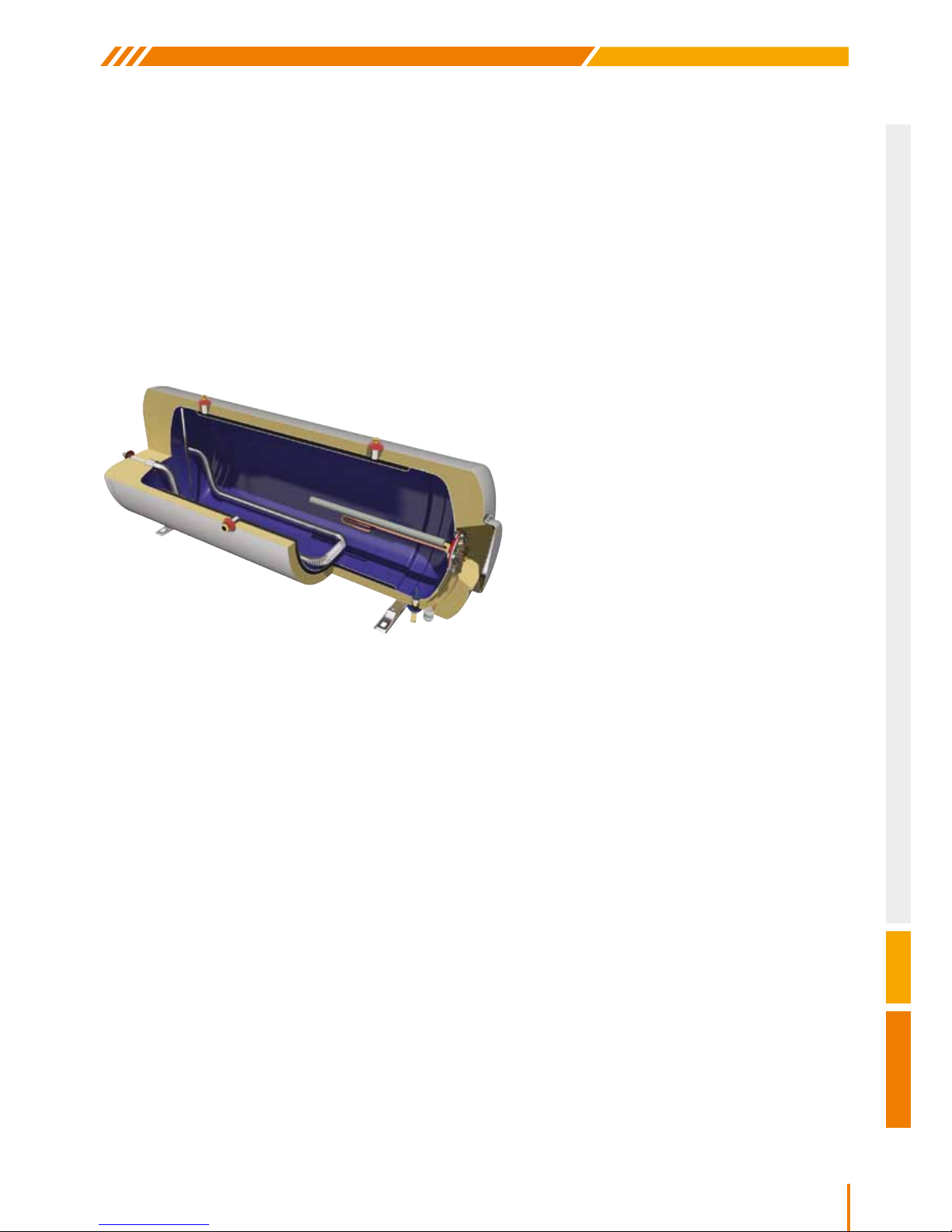
WATER STORAGE TANK SPECIFICATIONS
STEEL - ENAMEL
1. Water tank: 2.5mm thickness cold rolled steel with a double internal layer of enamel, red at 860°C according to
DIN 4753. The enameling is done in our own high tech industrial facilities. The water storage tanks are checked
individually upon exit from the enameling unit, assuring the top quality of the enamel.
2. Surrounding heat exchanger (Jacket) with internal expansion tank of cold rolled steel, for the operation of the
closed loop, which is compulsory at low temperatures and also in areas with water with high mineral content.
3. Thermal insulation: the ecological, expanded polyurethane of high-density (>50kg/m
3
) ensures minimum heat
loss, maintaining the hot water temperature.
4. External housing: naval aluminium alloy.
5. Cathode protection by magnesium anode
Ø26x500mm/500gr for effective protection
against corrosion and mineral deposits caused
by electrolytic reactions.
6. Large round galvanized steel ange
rubber protected: innovative, smart design
for the quick cleaning of minerals, fast
replacement of anode and immediate access
to the electrical components.
7. Complete sealing rubber of silicone, non
toxic material, which does not permit water to
contact the ange, thus protecting it against
electrolysis and corrosion, specially made to
withstand the generally accepted specications
with regard to the heat resistance.
8. Heating element rated according to the country of destination local regulations. (Optional, for the use of electricity
as an auxiliary power source). All electrical components carry the CE marking according to EN 60335-1 and
EN60335-2-21 standards.
9. Overheating protection with closed loop connection through a stainless steel exible hose.
10. Automatic regulated thermostat with bipolar protection and auxiliary fuse. All electrical components carry the
CE marking according to EN 60335-1 and EN60335-2-21 standards.
11. Protective cover: designed to ensure the proper ventilation of the electrical section and its protection from the
environmental conditions.
Gland: for sealing the passage of the heating element’s connection cable.
12. Cold water inlet: 1/2” BSP male threaded pipe end for water stratication and 10 bar safety valve for releasing
pressure.
13. Hot water outlet: 1/2” BSP male threaded pipe end.
14. Jacket inlet: 3/4” BSP male threaded pipe end.
15. Jacket outlet: 3/4” BSP male threaded pipe end.
16. 3.5 bar safety valve connection location: brass 1/2” BSP male threaded pipe end.
17. Closed loop circuit lling point: brass 1/2” BSP male threaded pipe end.
18. Heat exchanger with 3/4” BSP female threaded pipe ends, made of stainless steel house, large exchange
surface (160lt & 200lt: 0.38m
2
, 320lt: 0.76m2) for use of the heating produced by central heating systems during
the winter (optional)
Page 8
8
Nobel Xilinakis D. & Co preserves the right to change all specications of the products and their accessories without prior notice
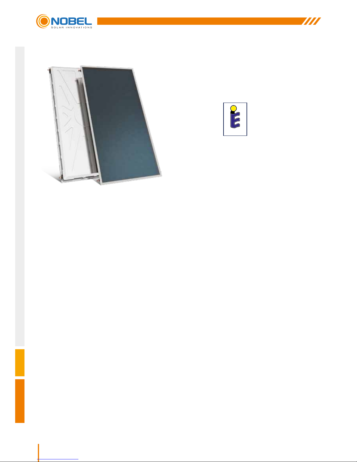
COLLECTOR APOLLON AL SPECIFICATIONS
1. External one piece aluminium trough of high aesthetics, shaped by deep drawing method in 400 tn capacity
press, made of naval aluminium alloy, rich in magnesium. Robust construction for perfect tightness.
2. High density, eco-friendly thermal insulation achieved with a 60mm thick layer of prepressed rockwool with a
covering of black glass fabric for the minimization of thermal losses.
Rockwool insulation thermal conductivity: λ=0.035 W/m grd (DIN 56612, measured at 0°C)
3. Water frame of copper pipes of suitable gauge and thickness (headers: Ø22, manifolds: Ø8) Headers are
punched with upper expansion, for perfect manifolds tting, thus avoiding pressure drop in the collectors.
(tube pitch) = 93mm (EN 1652).
4. Sun-Selective complete area absorber made of selective aluminium sheet with a special titan coating formed
in vacuum,of high absorbency and low radiation, covers the complete window area as well as the headers, thus
increasing the collector’s absorbency, Laser Welded to the water frame.
5. Special plastic parts for supporting and sealing the water frame to the trough, specially designed for the
collector’s ventilation, with sensor supporting option.
Special silicone rubber seals allow uctuation of the absorber’s length (contraction - expansion) in a -40°C
to +200°C temperature range.
6. Tempered solar glass low iron, with a stable coefcient of expansion and high light transmittance, can withstand
adverse weather conditions (e.g. hail storm, extreme temperature changes, etc.).
7. Solar glass rubber seal: UV proofed
8. Alluminium prole electrostatically painted (Al Mg Si 05): for solar glass seating and supporting.
Solar Keymark
Certied
E 22
Page 9
9
CLASSIC
Nobel Xilinakis D. & Co preserves the right to change all specications of the products and their accessories without prior notice
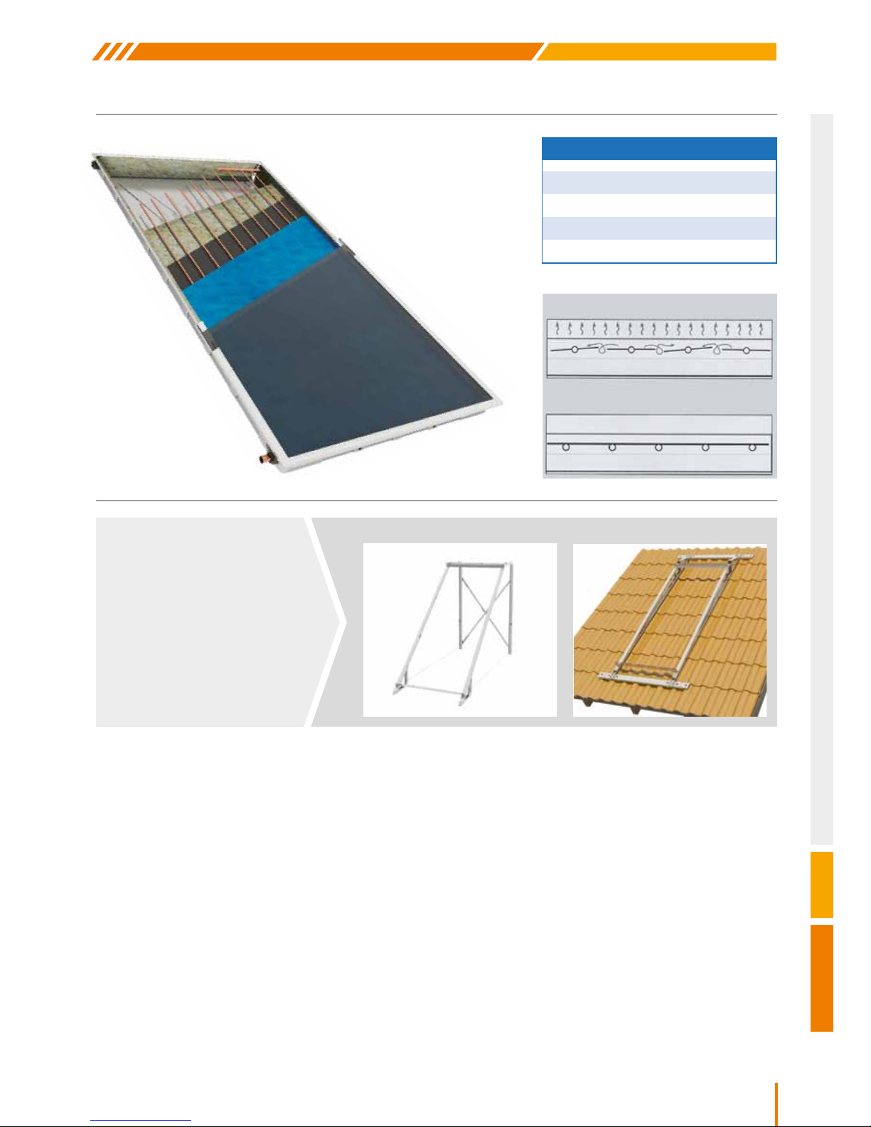
YEARLY ENERGY OUTPUT (kWh/m2)
ATHENS - GREECE 614
DAVOS - SWITZERLAND 795
WÜRZBURG - GERMANY 571
STOCKHOLM - SWEDEN 535
Normal absorber design with louvers.
Air turbulence increases heat loss
Complete area technology
The uniform area prevents heat loss
FLAT SURFACE INCLINED SURFACE
One type of supporting base
system, electrostatically painted,
made of 2.5mm thick galvanised
steel, with stainless steel screws
and nuts for installation on at
or inclined surfaces
SUPPORT BASE
Page 10
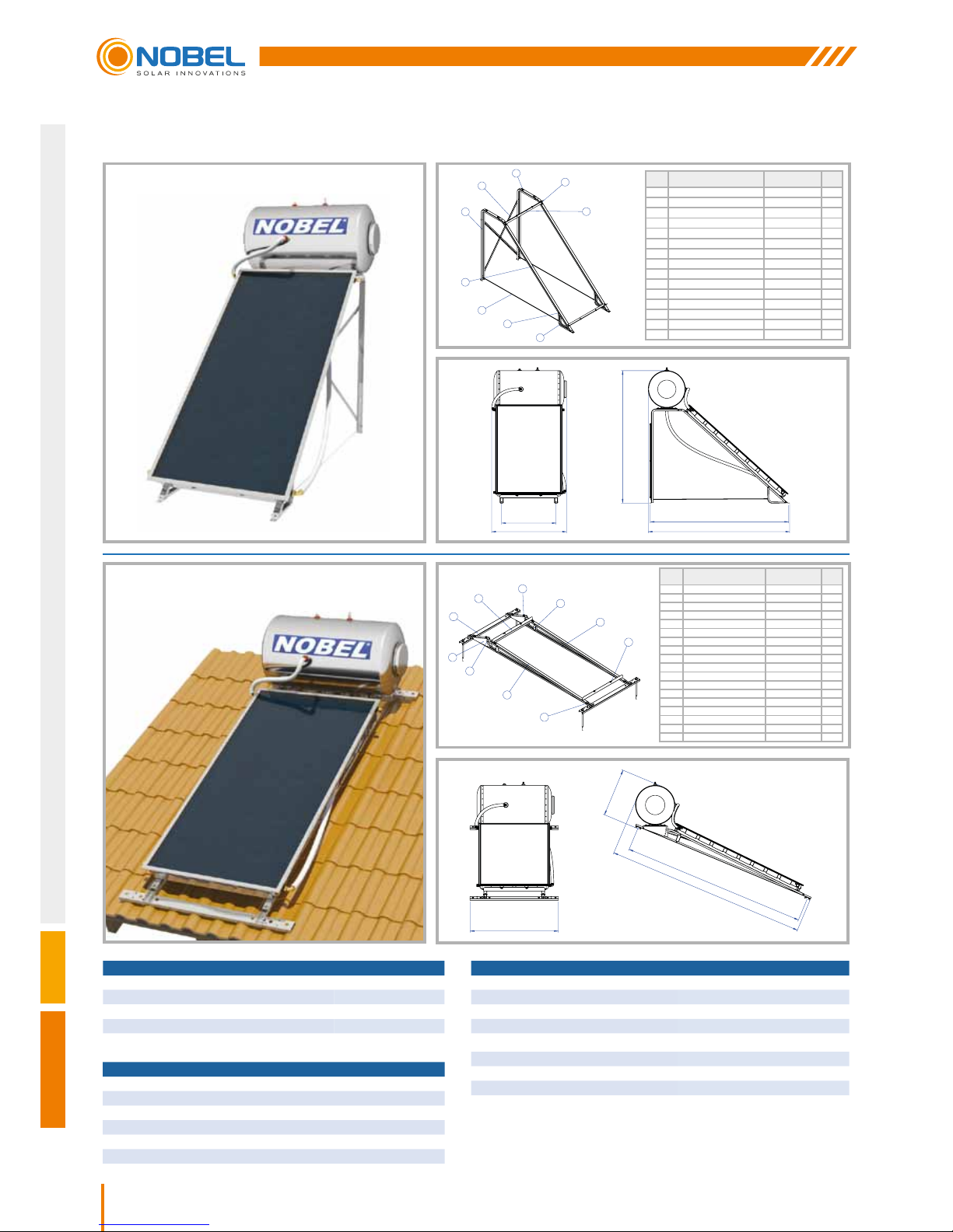
10
Nobel Xilinakis D. & Co preserves the right to change all specications of the products and their accessories without prior notice
WATER STORAGE TANK 120lt
DIMENSIONS (mm) 560x1095
WEIGHT EMPTY (kg) 49
JACKET CAPACITY (lt) 8.6
JACKET SURFACE (m
2
) 0.6
MAX. TEST PRESSURE (bar) 15
MAX. OPERATING PRESSURE (bar) 10
COLLECTOR APOLLON AL 2000
TOTAL AREA (m
2
)
2.03
NUMBER OF MANIFOLDS
10
HEAT TRANSFER MEDIUM PROPYLENE GLYCOL SOLUTION
CAPACITY (lt)
1.75
ABSORBER SURFACE (m2)
1.8
TOTAL DIMENSIONS (mm)
2010x1010x110
COLLECTOR TOTAL WEIGHT (without liquid) (kg)
38
ABSORBER SUN - SELECTIVE ALUMINIUM
ABSORBENCY / RADIATION COEFFICIENT
95% +/-2% / 5% +/-2%
TOTAL SYSTEM 120lt/2m
2
NUMBER OF COLLECTORS 1
SYSTEM WEIGHT EMPTY (Packed) / FULL (kg) 108 / 227
MAX. WATER TANK OPERATING PRESSURE (bar) 10
MAXIMUM PRESSURE CLOSED CIRCUIT (bar) 3.5
Note: All dimensions measured in mm
SOLAR WATER HEATER 120lt/2m2
120lt/2m2
FLAT SURFACE
120lt/2m2
INCLINED SURFACE
ITEM PART ΝΑΜΕ DIMΕΝSIONS QTY.
1 Beam Π 100x2x1800mm 2
2 Beam Π 90x2x2550mm 2
3 Beam Π 80x2x500mm 2
4 Collector Support 870mm 2
5 Beam (Lam. section 33x2mm) 1400mm 2
6 Screw Rod M8x1770mm 2
7 Hexagon Head Bolt M8 M8x20 13
8 Hexagon Head Bolt M8 M8x25 4
9 Hex Nut M8 25
10 Hexagon Head Bolt M6 M6x50 4
11 Hex Nut M6 4
12 Washer Ø8 12
13 Washer Ø10 4
14 Screw 8x60 4
15 Upat D10 4
ITEM PART ΝΑΜΕ DIMΕΝSIONS QTY.
1 Beam Π 90x2x2500mm 2
2 Beam Π 80x2x2690mm 2
3 Beam Π 90x2x135mm 2
4 Collector Support 870mm 2
5 Beam Π 125x1252mm 2
6 Angle Adjuster 2
7 Screw Rod Μ20xØ9 4
8 Hexagon Head Bolt M8 M8x20 20
9 Hexagon Head Bolt M8 M8x25 4
10 Hexagon Head Bolt M8 M8x60 4
11 Hexagon Head Bolt M6 M6x50 2
12 Hex Nut M20 8
13 Hex Nut M8 26
14 Hex Nut M6 2
15 Washer Ø20 8
16 Washer Ø10 4
17 Washer Ø8 12
18 Rivet with Thread M8 FAR 2
1
2
4
5
3
6
7
8
10
2
1
5
4
6
3
9
10
11
8
1252
684
2601
2853
820
1128
1996
2084
2130
Page 11
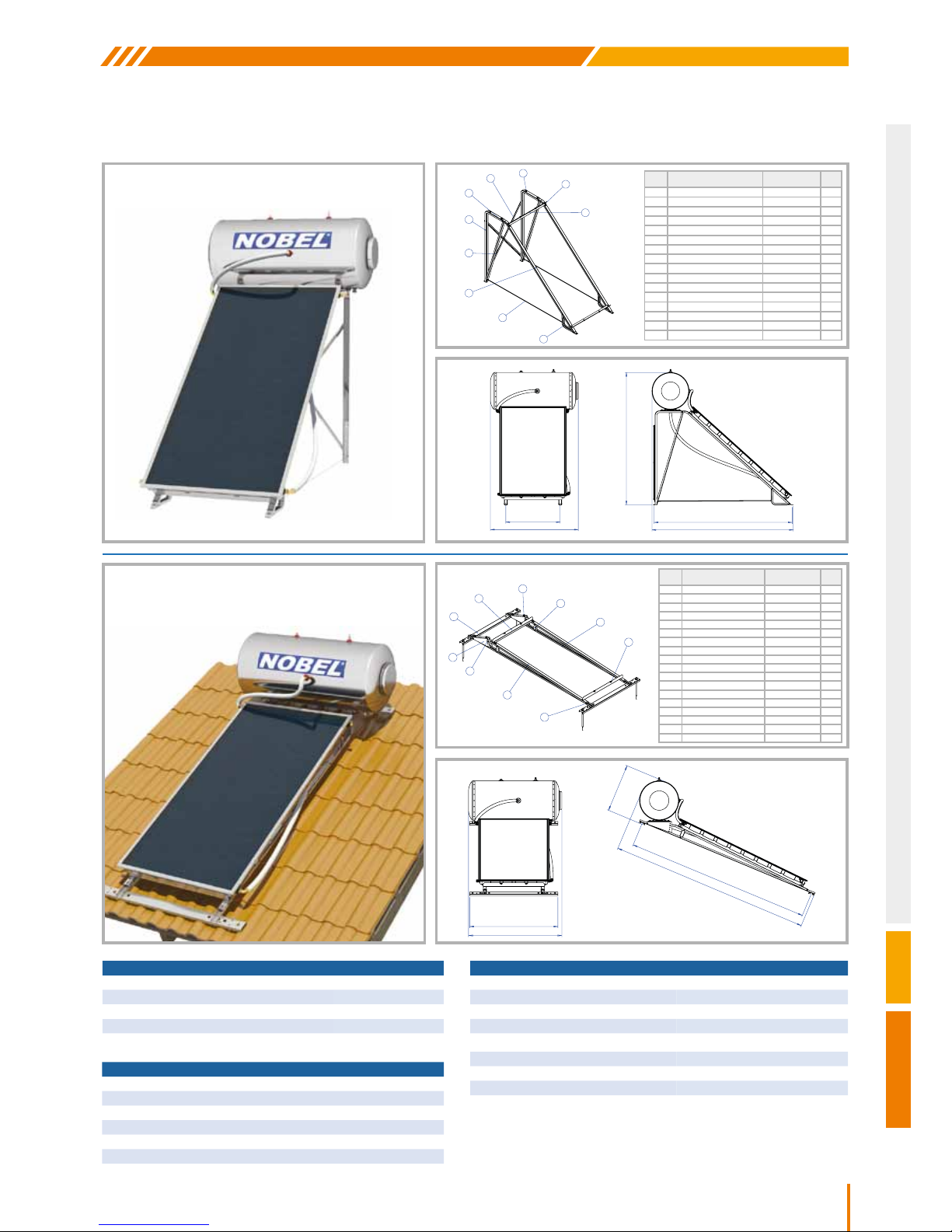
11
CLASSIC
Nobel Xilinakis D. & Co preserves the right to change all specications of the products and their accessories without prior notice
WATER STORAGE TANK 160lt
DIMENSIONS (mm) 560x1325
WEIGHT EMPTY (kg) 60
JACKET CAPACITY (lt) 12.9
JACKET SURFACE (m
2
) 0.9
MAX. TEST PRESSURE (bar) 15
MAX. OPERATING PRESSURE (bar) 10
COLLECTOR APOLLON AL 2000
TOTAL AREA (m
2
)
2.03
NUMBER OF MANIFOLDS
10
HEAT TRANSFER MEDIUM PROPYLENE GLYCOL SOLUTION
CAPACITY (lt)
1.75
ABSORBER SURFACE (m2)
1.8
TOTAL DIMENSIONS (mm)
2010x1010x110
COLLECTOR TOTAL WEIGHT (without liquid) (kg)
38
ABSORBER SUN - SELECTIVE ALUMINIUM
ABSORBENCY / RADIATION COEFFICIENT
95% +/-2% / 5% +/-2%
TOTAL SYSTEM 160lt/2m
2
NUMBER OF COLLECTORS 1
SYSTEM WEIGHT EMPTY (Packed) / FULL (kg) 122 / 278
MAX. WATER TANK OPERATING PRESSURE (bar) 10
MAXIMUM PRESSURE CLOSED CIRCUIT (bar) 3.5
Note: All dimensions measured in mm
SOLAR WATER HEATER 160lt/2m2
160lt/2m2
FLAT SURFACE
160lt/2m2
INCLINED SURFACE
ITEM PART ΝΑΜΕ DIMΕΝSIONS QTY.
1 Beam Π 100x2x1800mm 2
2 Beam Π 90x2x2550mm 2
3 Beam Π 80x2x500mm 2
4 Beam Π 80x2x1465mm 2
5 Collector Support 870mm 2
6 Beam (Lam. section 33x2mm) 1400mm 2
7 Screw Rod M8x1770mm 2
8 Hexagon Head Bolt M8 M8x20 13
9 Hexagon Head Bolt M8 M8x25 4
10 Hex Nut M8 25
11 Hexagon Head Bolt M6 M6x50 6
12 Hex Nut M6 6
13 Washer Ø8 12
14 Washer Ø10 4
15 Screw 8x60 4
16 Upat D10 4
ITEM PART ΝΑΜΕ DIMΕΝSIONS QTY.
1 Beam Π 90x2x2500mm 2
2 Beam Π 80x2x2690mm 2
3 Beam Π 90x2x135mm 2
4 Collector Support 870mm 2
5 Beam Π 125x1252mm 2
6 Angle Adjuster 2
7 Screw Rod Μ20xØ9 4
8 Hexagon Head Bolt M8 M8x20 20
9 Hexagon Head Bolt M8 M8x25 4
10 Hexagon Head Bolt M8 M8x60 4
11 Hexagon Head Bolt M6 M6x50 2
12 Hex Nut M20 8
13 Hex Nut M8 26
14 Hex Nut M6 2
15 Washer Ø20 8
16 Washer Ø10 4
17 Washer Ø8 12
18 Rivet with Thread M8 FAR 2
2
1
5
4
6
3
9
10
11
8
1
2
5
6
4
3
7
8
11
9
1252
1325
684
2601
2853
820
1325
1996
2084
2130
Page 12
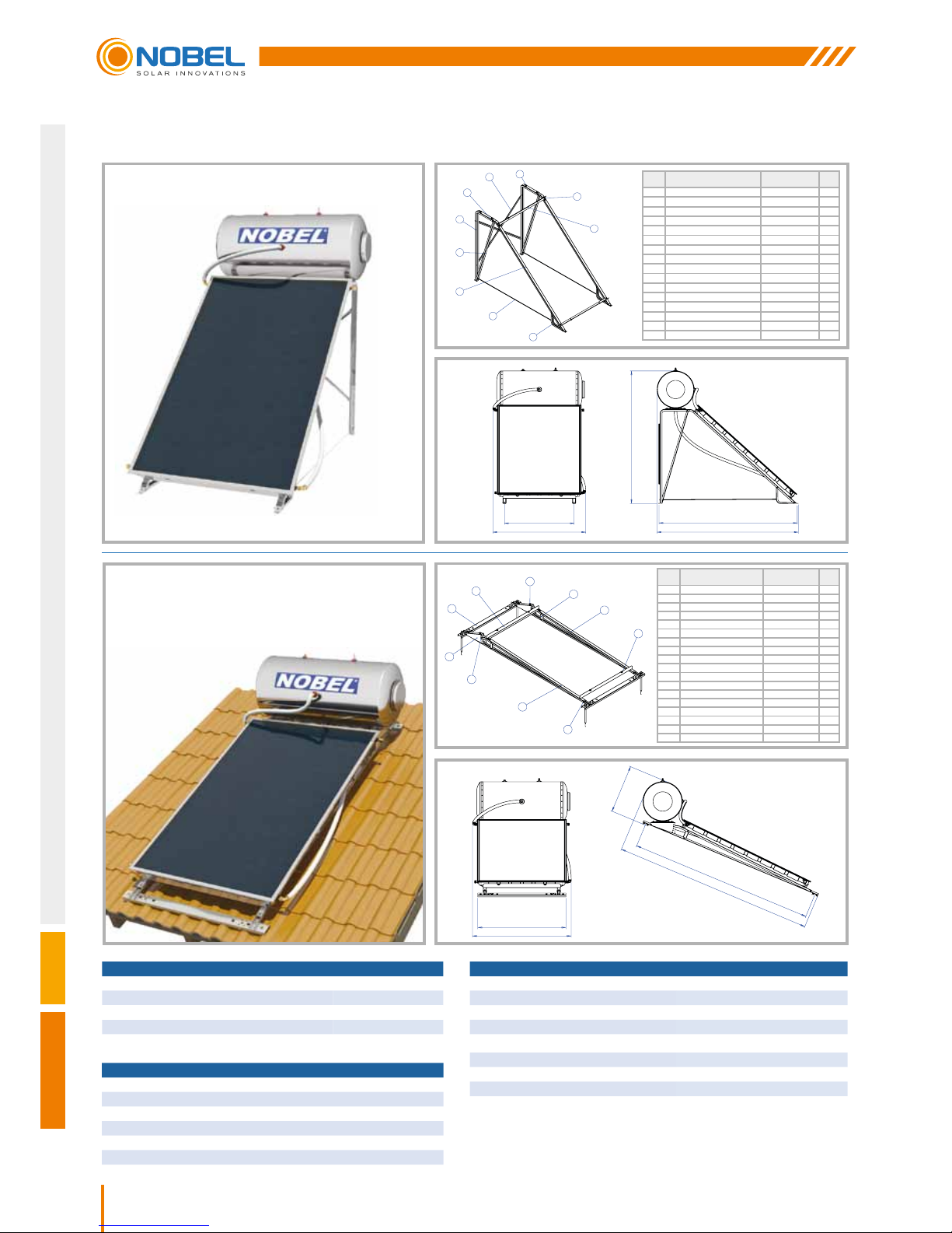
12
Nobel Xilinakis D. & Co preserves the right to change all specications of the products and their accessories without prior notice
WATER STORAGE TANK 160lt
DIMENSIONS (mm) 560x1325
WEIGHT EMPTY (kg) 60
JACKET CAPACITY (lt) 12.9
JACKET SURFACE (m
2
) 0.9
MAX. TEST PRESSURE (bar) 15
MAX. OPERATING PRESSURE (bar) 10
COLLECTOR APOLLON AL 2600
TOTAL AREA (m
2
)
2.53
NUMBER OF MANIFOLDS
13
HEAT TRANSFER MEDIUM PROPYLENE GLYCOL SOLUTION
CAPACITY (lt)
2.12
ABSORBER SURFACE (m2)
2.3
TOTAL DIMENSIONS (mm)
2010x1260x110
COLLECTOR TOTAL WEIGHT (without liquid) (kg)
45.4
ABSORBER SUN - SELECTIVE ALUMINIUM
ABSORBENCY / RADIATION COEFFICIENT
95% +/-2% / 5% +/-2%
TOTAL SYSTEM 160lt/2.6m
2
NUMBER OF COLLECTORS 1
SYSTEM WEIGHT EMPTY (Packed) / FULL (kg) 132 / 288
MAX. WATER TANK OPERATING PRESSURE (bar) 10
MAXIMUM PRESSURE CLOSED CIRCUIT (bar) 3.5
Note: All dimensions measured in mm
SOLAR WATER HEATER 160lt/2.6m2
160lt/2.6m2
FLAT SURFACE
160lt/2.6m2
INCLINED SURFACE
ITEM PART ΝΑΜΕ DIMΕΝSIONS QTY.
1 Beam Π 100x2x1800mm 2
2 Beam Π 90x2x2550mm 2
3 Beam Π 80x2x500mm 2
4 Beam Π 80x2x1465mm 2
5 Collector Support 1100mm 2
6 Beam (Lam. section 33x2mm) 1400mm 2
7 Screw Rod M8x1770mm 2
8 Hexagon Head Bolt M8 M8x20 13
9 Hexagon Head Bolt M8 M8x25 4
10 Hex Nut M8 25
11 Hexagon Head Bolt M6 M6x50 6
12 Hex Nut M6 6
13 Washer Ø8 12
14 Washer Ø10 4
15 Screw 8x60 4
16 Upat D10 4
ITEM PART ΝΑΜΕ DIMΕΝSIONS QTY.
1 Beam Π 90x2x2500mm 2
2 Beam Π 90x2x135mm 2
3 Beam Π 80x2x2690mm 2
4 Collector Support 1100mm 2
5 Beam Π 125x1252mm 2
6 Angle Adjuster 2
7 Screw Rod Μ20xØ9 4
8 Hexagon Head Bolt M8 M8x20 20
9 Hexagon Head Bolt M8 M8x25 4
10 Hexagon Head Bolt M8 M8x60 4
11 Hexagon Head Bolt M6 M6x50 2
12 Hex Nut M20 8
13 Hex Nut M8 26
14 Hex Nut M6 2
15 Washer Ø20 8
16 Washer Ø10 4
17 Washer Ø8 12
18 Rivet with Thread M8 FAR 2
1
2
5
6
4
3
7
8
11
9
3
1
5
4
6
2
9
8
10
11
1252
1401
684
2601
2853
1050
1401
1996
2084
2130
Page 13
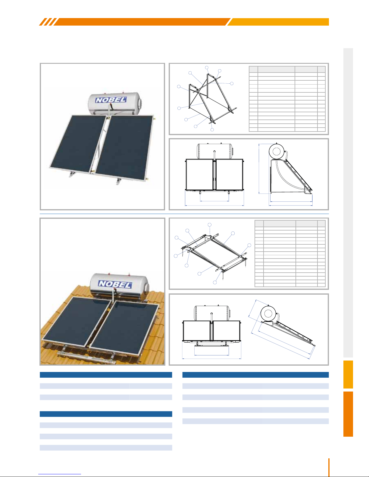
13
CLASSIC
Nobel Xilinakis D. & Co preserves the right to change all specications of the products and their accessories without prior notice
WATER STORAGE TANK 160lt
DIMENSIONS (mm) 560x1325
WEIGHT EMPTY (kg) 60
JACKET CAPACITY (lt) 12.9
JACKET SURFACE (m
2
) 0.9
MAX. TEST PRESSURE (bar) 15
MAX. OPERATING PRESSURE (bar) 10
COLLECTOR APOLLON AL 1500
TOTAL AREA (m
2
)
1.52
NUMBER OF MANIFOLDS
10
HEAT TRANSFER MEDIUM PROPYLENE GLYCOL SOLUTION
CAPACITY (lt)
1.45
ABSORBER SURFACE (m2)
1.3
TOTAL DIMENSIONS (mm)
1510x1010x110
COLLECTOR TOTAL WEIGHT (without liquid) (kg)
28
ABSORBER SUN - SELECTIVE ALUMINIUM
ABSORBENCY / RADIATION COEFFICIENT
95% +/-2% / 5% +/-2%
TOTAL SYSTEM 160lt/3m
2
NUMBER OF COLLECTORS 2
SYSTEM WEIGHT EMPTY (Packed) / FULL (kg) 138 / 293
MAX. WATER TANK OPERATING PRESSURE (bar) 10
MAXIMUM PRESSURE CLOSED CIRCUIT (bar) 3.5
SOLAR WATER HEATER 160lt/3m2
160lt/3m2
FLAT SURFACE
160lt/3m2
INCLINED SURFACE
ITEM PART ΝΑΜΕ DIMΕΝSIONS QTY.
1 Beam Π 90x2x2000mm 2
2 Beam Π 80x2x2170mm 2
3 Collector Support 1600mm 2
4 Beam Π 125x1252mm 2
5 Angle Adjuster 2
6 Screw Rod Μ20xØ9 4
7 Hexagon Head Bolt M8 M8X20 20
8 Hexagon Head Bolt M8 M8x25 4
9 Hexagon Head Bolt M8 M8x60 4
10 Hexagon Head Bolt M6 M6x50 2
11 Hex Nut M20 8
12 Hex Nut M8 22
13 Hex Nut M6 2
14 Washer Ø20 8
15 Washer Ø10 4
16 Washer Ø8 16
17 Rivet with Thread M8 FAR 2
ITEM PART ΝΑΜΕ DIMΕΝSIONS QTY.
1 Beam Π 100x2x1600mm 2
2 Beam Π 90x2x2050mm 2
3 Beam Π 80x2x500mm 2
4 Collector Support 1600mm 2
5 Beam (Lam. section 33x2mm) 1400mm 2
6 Screw Rod M8x1290mm 2
7 Hexagon Head Bolt M8 M8x20 17
8 Hexagon Head Bolt M8 M8x25 4
9 Hex Nut M8 25
10 Hexagon Head Bolt M6 M6x50 4
11 Hex Nut M6 4
12 Washer Ø8 16
13 Washer Ø10 4
14 Screw 8x60 4
15 Upat D10 4
1
2
4
5
6
7
8
3
10
2
1
4
3
5
8
7
9
10
2154
1252
685
2087
2334
1050
2154
6281
1533
1599
Page 14
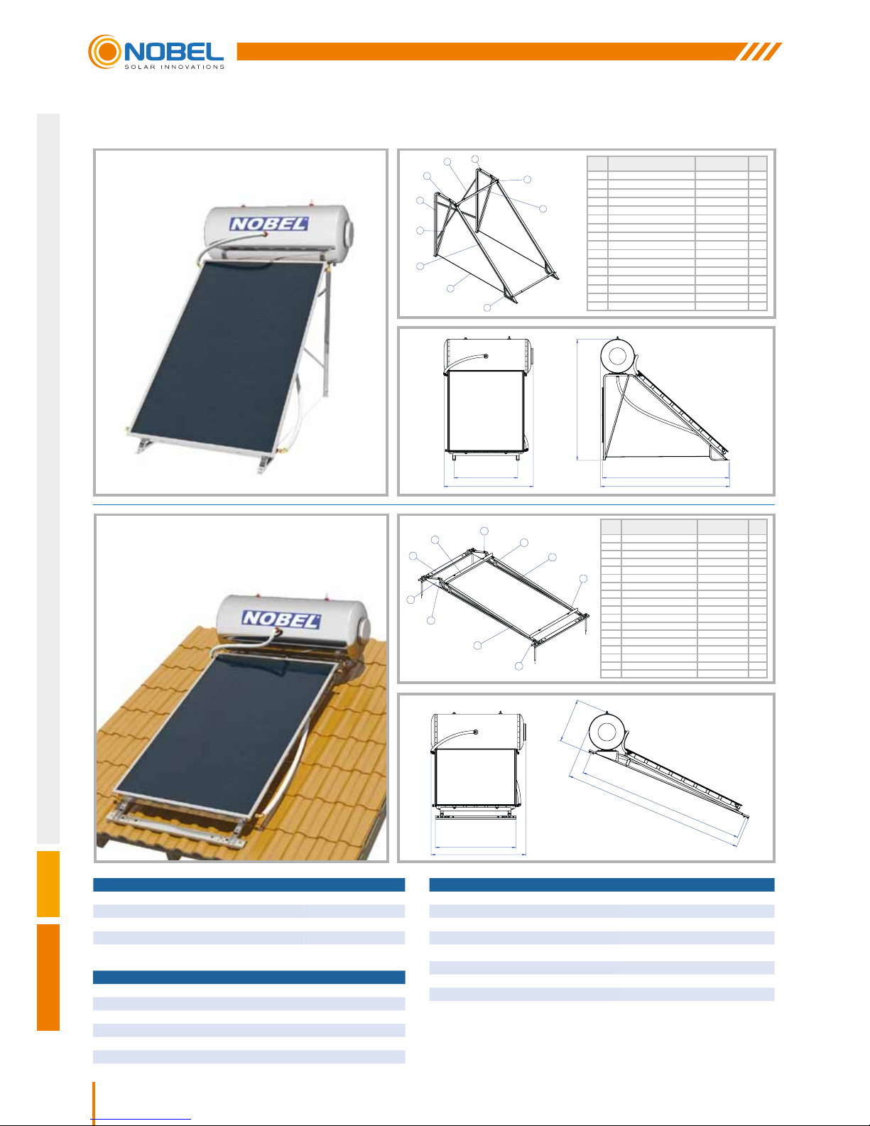
14
Nobel Xilinakis D. & Co preserves the right to change all specications of the products and their accessories without prior notice
WATER STORAGE TANK 200lt
DIMENSIONS (mm) 560x1475
WEIGHT EMPTY (kg) 72
JACKET CAPACITY (lt) 18.3
JACKET SURFACE (m
2
) 1.3
MAX. TEST PRESSURE (bar) 15
MAX. OPERATING PRESSURE (bar) 10
COLLECTOR APOLLON AL 2600
TOTAL AREA (m
2
)
2.53
NUMBER OF MANIFOLDS
13
HEAT TRANSFER MEDIUM PROPYLENE GLYCOL SOLUTION
CAPACITY (lt)
2.12
ABSORBER SURFACE (m2)
2.3
TOTAL DIMENSIONS (mm)
2010x1260x110
COLLECTOR TOTAL WEIGHT (without liquid) (kg)
45.4
ABSORBER SUN - SELECTIVE ALUMINIUM
ABSORBENCY / RADIATION COEFFICIENT
95% +/-2% / 5% +/-2%
TOTAL SYSTEM 200lt/2.6m
2
NUMBER OF COLLECTORS 1
SYSTEM WEIGHT EMPTY (Packed) / FULL (kg) 145 / 346
MAX. WATER TANK OPERATING PRESSURE (bar) 10
MAXIMUM PRESSURE CLOSED CIRCUIT (bar) 3.5
Note: All dimensions measured in mm
SOLAR WATER HEATER 200lt/2.6m2
200lt/2.6m2
FLAT SURFACE
200lt/2.6m2
INCLINED SURFACE
ITEM PART ΝΑΜΕ DIMΕΝSIONS QTY.
1 Beam Π 100x2x1800mm 2
2 Beam Π 90x2x2550mm 2
3 Beam Π 80x2x500mm 2
4 Beam Π 80x2x1465mm 2
5 Collector Support 1100mm 2
6 Beam (Lam. section 33x2mm) 1400mm 2
7 Screw Rod M8x1770mm 2
8 Hexagon Head Bolt M8 M8x20 13
9 Hexagon Head Bolt M8 M8x25 4
10 Hex Nut M8 25
11 Hexagon Head Bolt M6 M6x50 6
12 Hex Nut M6 6
13 Washer Ø8 12
14 Washer Ø10 4
15 Screw 8x60 4
16 Upat D10 4
ITEM PART ΝΑΜΕ DIMΕΝSIONS QTY.
1 Beam Π 90x2x2500mm 2
2 Beam Π 90x2x135mm 2
3 Beam Π 80x2x2690mm 2
4 Collector Support 1100mm 2
5 Beam Π 125x1252mm 2
6 Angle Adjuster 2
7 Screw Rod Μ20xØ9 4
8 Hexagon Head Bolt M8 M8x20 20
9 Hexagon Head Bolt M8 M8x25 4
10 Hexagon Head Bolt M8 M8x60 4
11 Hexagon Head Bolt M6 M6x50 2
12 Hex Nut M20 8
13 Hex Nut M8 26
14 Hex Nut M6 2
15 Washer Ø20 8
16 Washer Ø10 4
17 Washer Ø8 12
18 Rivet with Thread M8 FAR 2
1
2
5
6
4
3
7
8
11
9
3
1
5
4
6
2
9
8
10
11
1252
1475
684
2601
2853
1050
1475
1996
2084
2130
Page 15
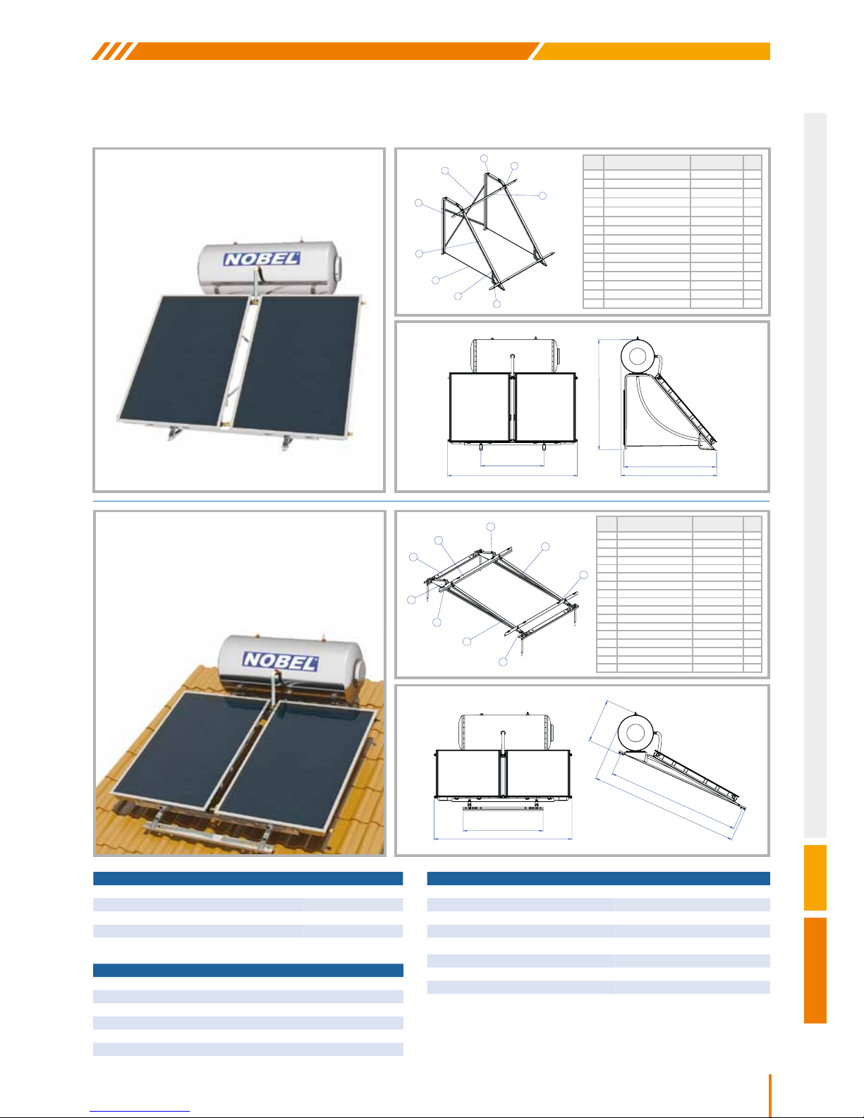
15
CLASSIC
Nobel Xilinakis D. & Co preserves the right to change all specications of the products and their accessories without prior notice
WATER STORAGE TANK 200lt
DIMENSIONS (mm) 560x1475
WEIGHT EMPTY (kg) 72
JACKET CAPACITY (lt) 18.3
JACKET SURFACE (m
2
) 1.3
MAX. TEST PRESSURE (bar) 15
MAX. OPERATING PRESSURE (bar) 10
COLLECTOR APOLLON AL 1500
TOTAL AREA (m
2
)
1.52
NUMBER OF MANIFOLDS
10
HEAT TRANSFER MEDIUM PROPYLENE GLYCOL SOLUTION
CAPACITY (lt)
1.45
ABSORBER SURFACE (m2)
1.3
TOTAL DIMENSIONS (mm)
1510x1010x110
COLLECTOR TOTAL WEIGHT (without liquid) (kg)
28
ABSORBER SUN - SELECTIVE ALUMINIUM
ABSORBENCY / RADIATION COEFFICIENT
95% +/-2% / 5% +/-2%
TOTAL SYSTEM 200lt/3m
2
NUMBER OF COLLECTORS 2
SYSTEM WEIGHT EMPTY (Packed) / FULL (kg) 151 / 352
MAX. WATER TANK OPERATING PRESSURE (bar) 10
MAXIMUM PRESSURE CLOSED CIRCUIT (bar) 3.5
Note: All dimensions measured in mm
200lt/3m2
FLAT SURFACE
200lt/3m2
INCLINED SURFACE
SOLAR WATER HEATER 200lt/3m2
ITEM PART ΝΑΜΕ DIMΕΝSIONS QTY.
1 Beam Π 90x2x2000mm 2
2 Beam Π 80x2x2170mm 2
3 Collector Support 1600mm 2
4 Beam Π 125x1252mm 2
5 Angle Adjuster 2
6 Screw Rod Μ20xØ9 4
7 Hexagon Head Bolt M8 M8X20 20
8 Hexagon Head Bolt M8 M8x25 4
9 Hexagon Head Bolt M8 M8x60 4
10 Hexagon Head Bolt M6 M6x50 2
11 Hex Nut M20 8
12 Hex Nut M8 22
13 Hex Nut M6 2
14 Washer Ø20 8
15 Washer Ø10 4
16 Washer Ø8 16
17 Rivet with Thread M8 FAR 2
ITEM PART ΝΑΜΕ DIMΕΝSIONS QTY.
1 Beam Π 100x2x1600mm 2
2 Beam Π 90x2x2050mm 2
3 Beam Π 80x2x500mm 2
4 Collector Support 1600mm 2
5 Beam (Lam. section 33x2mm) 1400mm 2
6 Screw Rod M8x1290mm 2
7 Hexagon Head Bolt M8 M8x20 17
8 Hexagon Head Bolt M8 M8x25 4
9 Hex Nut M8 25
10 Hexagon Head Bolt M6 M6x50 4
11 Hex Nut M6 4
12 Washer Ø8 16
13 Washer Ø10 4
14 Screw 8x60 4
15 Upat D10 4
1
2
4
5
6
7
8
3
10
2
1
4
3
5
8
7
9
10
2154
1252
685
2087
2334
1050
2154
6281
1533
1599
Page 16
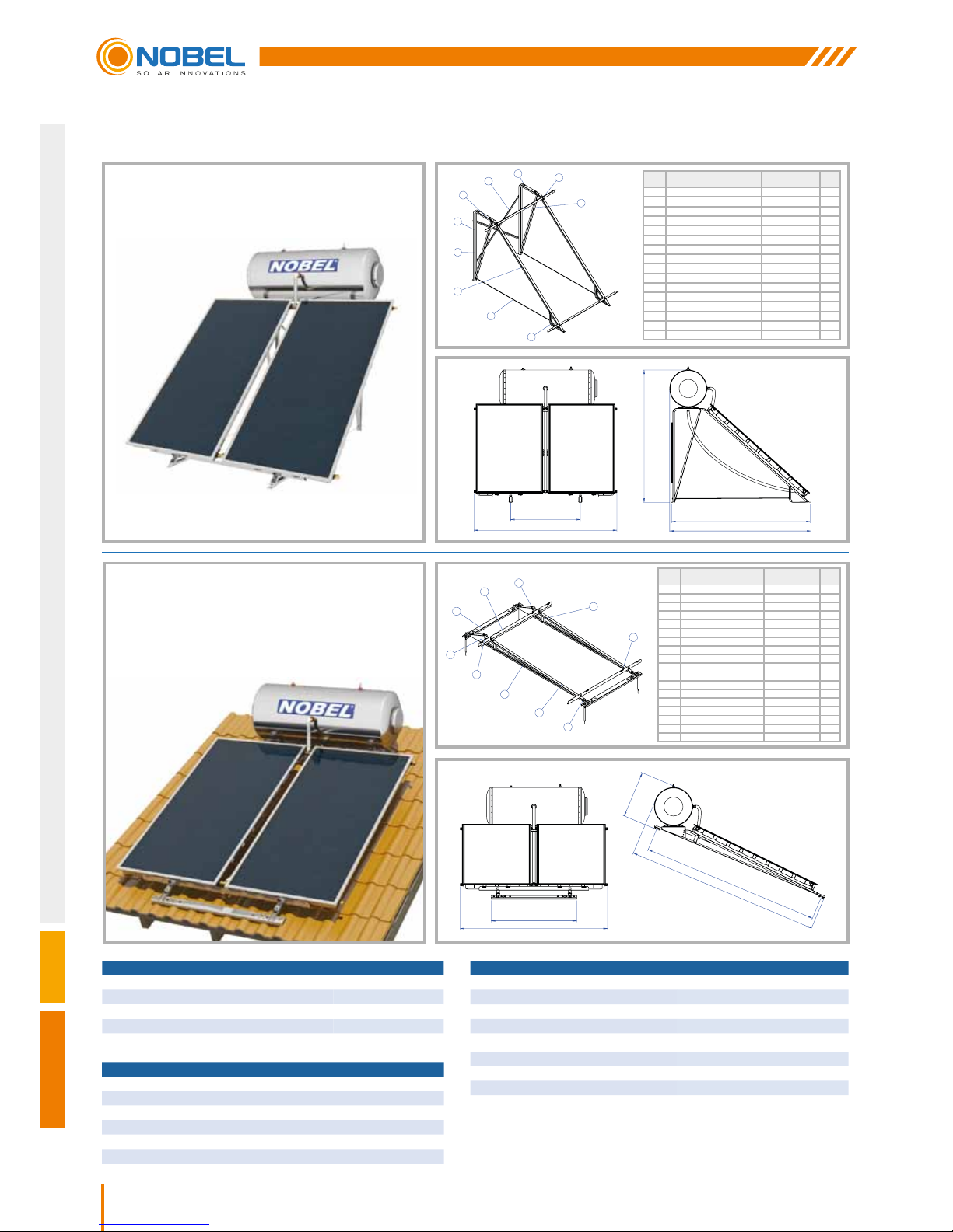
16
Nobel Xilinakis D. & Co preserves the right to change all specications of the products and their accessories without prior notice
WATER STORAGE TANK 200lt
DIMENSIONS (mm) 560x1475
WEIGHT EMPTY (kg) 72
JACKET CAPACITY (lt) 18.3
JACKET SURFACE (m
2
) 1.3
MAX. TEST PRESSURE (bar) 15
MAX. OPERATING PRESSURE (bar) 10
COLLECTOR APOLLON AL 2000
TOTAL AREA (m
2
)
2.03
NUMBER OF MANIFOLDS
10
HEAT TRANSFER MEDIUM PROPYLENE GLYCOL SOLUTION
CAPACITY (lt)
1.75
ABSORBER SURFACE (m2)
1.8
TOTAL DIMENSIONS (mm)
2010x1010x110
COLLECTOR TOTAL WEIGHT (without liquid) (kg)
38
ABSORBER SUN - SELECTIVE ALUMINIUM
ABSORBENCY / RADIATION COEFFICIENT
95% +/-2% / 5% +/-2%
TOTAL SYSTEM 200lt/4m
2
NUMBER OF COLLECTORS 2
SYSTEM WEIGHT EMPTY (Packed) / FULL (kg) 174 / 374
MAX. WATER TANK OPERATING PRESSURE (bar) 10
MAXIMUM PRESSURE CLOSED CIRCUIT (bar) 3.5
Note: All dimensions measured in mm
SOLAR WATER HEATER 200lt/4m2
200lt/4m2
FLAT SURFACE
200lt/4m2
INCLINED SURFACE
ITEM PART ΝΑΜΕ DIMΕΝSIONS QTY.
1 Beam Π 100x2x1800mm 2
2 Beam Π 90x2x2550mm 2
3 Beam Π 80x2x500mm 2
4 Beam Π 80x2x1465mm 2
5 Collector Support 1600mm 2
6 Beam (Lam. section 33x2mm) 1400mm 2
7 Screw Rod M8x1770mm 2
8 Hexagon Head Bolt M8 M8x20 17
9 Hexagon Head Bolt M8 M8x25 4
10 Hex Nut M8 25
11 Hexagon Head Bolt M6 M6x50 6
12 Hex Nut M6 6
13 Washer Ø8 16
14 Washer Ø10 4
15 Screw 8x60 4
16 Upat D10 4
ITEM PART ΝΑΜΕ DIMΕΝSIONS QTY.
1 Beam Π 90x2x2500mm 2
2 Beam Π 80x2x2690mm 2
3 Beam Π 90x2x135mm 2
4 Collector Support 1600mm 2
5 Beam Π 125x1252mm 2
6 Angle Adjuster 2
7 Screw Rod Μ20xØ9 4
8 Hexagon Head Bolt M8 M8X20 24
9 Hexagon Head Bolt M8 M8x25 4
10 Hexagon Head Bolt M8 M8x60 4
11 Hexagon Head Bolt M6 M6x50 2
12 Hex Nut M20 8
13 Hex Nut M8 26
14 Hex Nut M6 2
15 Washer Ø20 8
16 Washer Ø10 4
17 Washer Ø8 16
18 Rivet with Thread M8 FAR 2
1
2
5
6
4
3
7
8
11
9
2
1
5
4
6
3
9
8
10
11
2154
1252
684
2601
2853
1050
2154
1996
2084
2130
Page 17
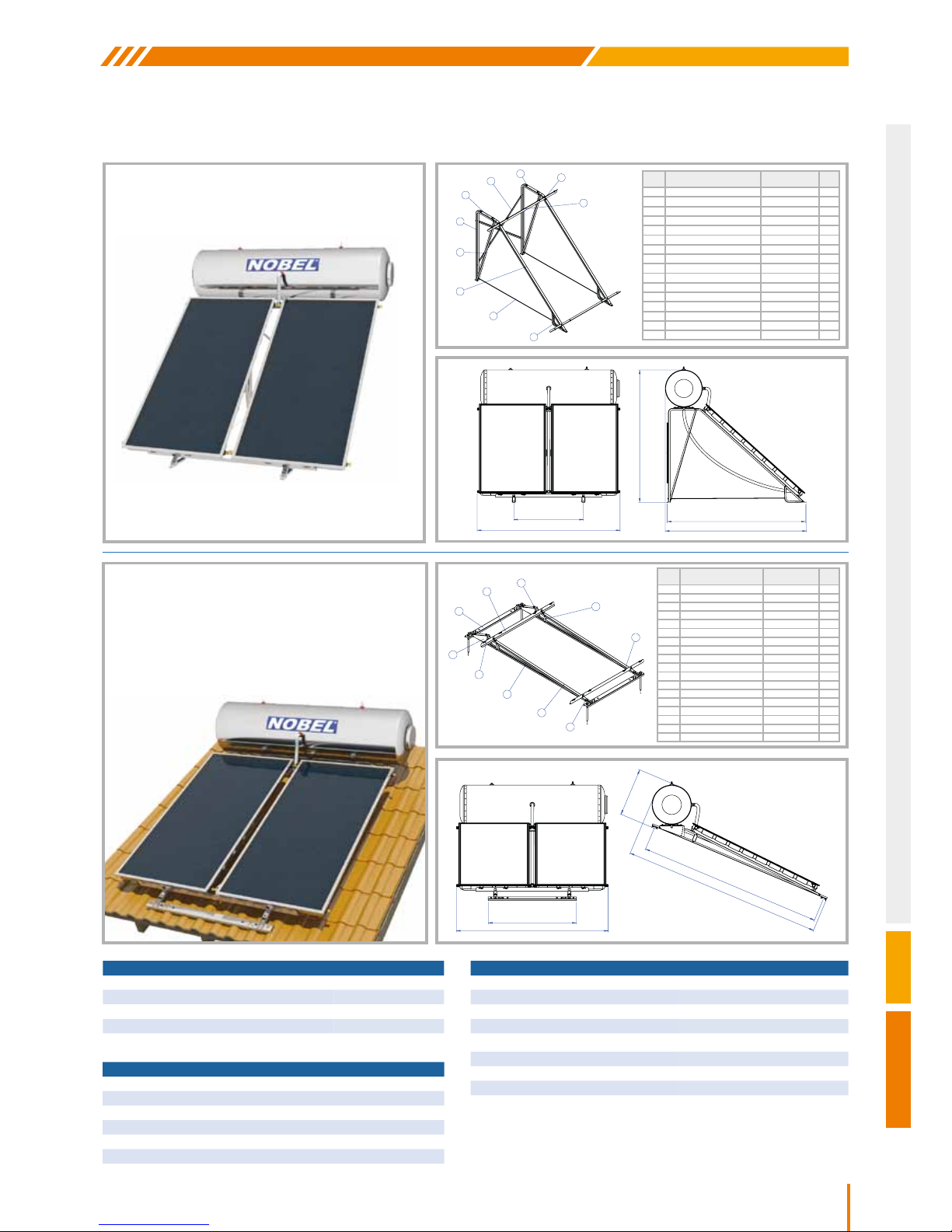
17
CLASSIC
Nobel Xilinakis D. & Co preserves the right to change all specications of the products and their accessories without prior notice
WATER STORAGE TANK 320lt
DIMENSIONS (mm) 560x2095
WEIGHT EMPTY (kg) 104
JACKET CAPACITY (lt) 25.8
JACKET SURFACE (m
2
) 1.8
MAX. TEST PRESSURE (bar) 15
MAX. OPERATING PRESSURE (bar) 10
COLLECTOR APOLLON AL 2000
TOTAL AREA (m
2
)
2.03
NUMBER OF MANIFOLDS
10
HEAT TRANSFER MEDIUM PROPYLENE GLYCOL SOLUTION
CAPACITY (lt)
1.75
ABSORBER SURFACE (m2)
1.8
TOTAL DIMENSIONS (mm)
2010x1010x110
COLLECTOR TOTAL WEIGHT (without liquid) (kg)
38
ABSORBER SUN - SELECTIVE ALUMINIUM
ABSORBENCY / RADIATION COEFFICIENT
95% +/-2% / 5% +/-2%
TOTAL SYSTEM 320lt/4m
2
NUMBER OF COLLECTORS 2
SYSTEM WEIGHT EMPTY (Packed) / FULL (kg) 205 / 534
MAX. WATER TANK OPERATING PRESSURE (bar) 10
MAXIMUM PRESSURE CLOSED CIRCUIT (bar) 3.5
Note: All dimensions measured in mm
SOLAR WATER HEATER 320lt/4m2
320lt/4m2
FLAT SURFACE
320lt/4m2
INCLINED SURFACE
ITEM PART ΝΑΜΕ DIMΕΝSIONS QTY.
1 Beam Π 100x2x1800mm 2
2 Beam Π 90x2x2550mm 2
3 Beam Π 80x2x500mm 2
4 Beam Π 80x2x1465mm 2
5 Collector Support 1600mm 2
6 Beam (Lam. section 33x2mm) 1400mm 2
7 Screw Rod M8x1770mm 2
8 Hexagon Head Bolt M8 M8x20 17
9 Hexagon Head Bolt M8 M8x25 4
10 Hex Nut M8 25
11 Hexagon Head Bolt M6 M6x50 6
12 Hex Nut M6 6
13 Washer Ø8 16
14 Washer Ø10 4
15 Screw 8x60 4
16 Upat D10 4
ITEM PART ΝΑΜΕ DIMΕΝSIONS QTY.
1 Beam Π 90x2x2500mm 2
2 Beam Π 80x2x2690mm 2
3 Beam Π 90x2x135mm 2
4 Collector Support 1600mm 2
5 Beam Π 125x1252mm 2
6 Angle Adjuster 2
7 Screw Rod Μ20xØ9 4
8 Hexagon Head Bolt M8 M8X20 24
9 Hexagon Head Bolt M8 M8x25 4
10 Hexagon Head Bolt M8 M8x60 4
11 Hexagon Head Bolt M6 M6x50 2
12 Hex Nut M20 8
13 Hex Nut M8 26
14 Hex Nut M6 2
15 Washer Ø20 8
16 Washer Ø10 4
17 Washer Ø8 16
18 Rivet with Thread M8 FAR 2
1
2
5
6
4
3
7
8
11
9
2
1
5
4
6
3
9
8
10
11
2154
1252
684
2601
2853
1050
2154
1996
2084
2130
Page 18
18
Nobel Xilinakis D. & Co preserves the right to change all specications of the products and their accessories without prior notice
GENERAL INSTALLATION RULES
ATTENTION: Installation must be in compliance with local & national rules concerning water and electrical
installations (plumbing, electricity, hygiene, urban and others).
The solar system’s packaging must be removed at the site of installation in order to protect the device from shocks
during its transportation, making sure that the collectors are not supported on their pipe joints. Until installation is
completed, the collector’s glass must remain covered until the water storage tank is lled with domestic water, so as
to avoid the boiling of the lling liquid or the breaking of the glass. The plastic protective caps must be removed from
the water storage tank’s and the collectors’ pipe joints.
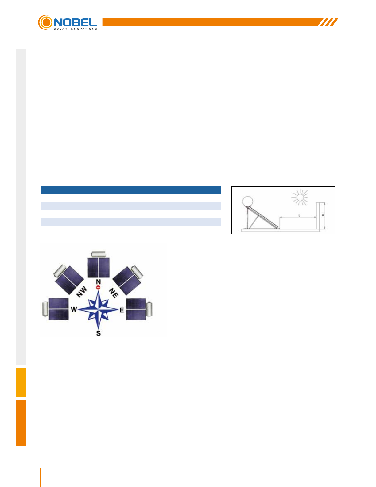
Installation location - shading: Prior to installation, a proper selection of the location must be made by the installer
(in agreement with the customer), and the surface must be checked (taking into consideration its static resistance),
so that it can bear the weight of the system.
On inclined roofs the system should not be placed between two beams but above a single one.
The position chosen for the solar water heater installation should not be shaded by any obstacles such as trees,
buildings and other all year round, so as to ensure at least 4 hours of uninhibited exposure of the collector to the sun
during the midday hours.
LATITUDE DISTANCE BETWEEN THE OBSTACLE AND THE COLLECTOR (L)
0°
- 25°
1.0 x H
26°
- 35°
1.5 x H
36°
- 45°
2.0 x H
46°
- 50°
2.5 x H
> 50°
3.0 x H
Any deviation means a reduction in the system’s performance. If a deviation from the proper orientation cannot
be avoided, then the system’s performance should be corrected by increasing the collector surface, following a
study and evaluation of the specic conditions that apply. As the sun ray’s angle of attack varies with time but also
depending on the system’s location, the collector’s angle should be approximately equal to the installation location’s
latitude. At this angle the maximum energy gain on an annual basis is achieved.
Installation particularities: In case there is no compatibility between the surface where the solar water heater will be
installed (inclined or at) and the standard equipment provided with the system, a different kind of equipment should
be used. The responsibility for the equipment chosen lies on the installer and in no case on the company. It is up to
the installer to propose & install the different equipment required, who must previously agree it with the customer.
Special weather conditions: In regions suffering from heavy snowfalls, please make sure that the snow is always
timely removed. For this case and cases of regions with storms, high wind velocity, rainfall, cyclones, tornadoes, the
system must be placed on the roof as rmly as possible and must be tightened with extra metal stripes. In areas
where these conditions occur and hail of more than 20mm in diameter is to be observed, it is recommended that
insurance for the solar water heater is issued. In every case, it is recommended to secure your solar water heater on
the support base system with more metal belts than those provided.
Orientation - optimum angle: a basic factor for the system’s
optimum performance is the selection of its angle and orientation
for its particular location and the time during which the maximum
gain is required.
The solar system should be positioned so that the collector’s
surface faces the geographical south, if the installation takes
place in the Northern Hemisphere (and the geographical north for
the Southern Hemisphere), i.e. it should always face the Equator.
Page 19

19
CLASSIC
Nobel Xilinakis D. & Co preserves the right to change all specications of the products and their accessories without prior notice
Piping: the routing of the piping and cabling must be agreed upon between the installer and the client, so as to ensure
the proper installation of the solar system in compliance with local rules concerning water and electrical installations.
Make sure that the tubes connecting the storage tank with the collector and the piping to/from the water heater
are insulated in such a way that they can withstand temperatures covering the range of: -30°C to 120°C. Anti-UV
protection must be used for the insulation.
Antifreeze Liquid: The special heat transfer medium used in the closed circuit protects the system from freezing and
from salt accumulation inside the collector tubes. The jacket in which the heat transfer medium’s circulation takes
place, does not communicate with the water tank. The thermal uid must be well mixed with water in a percentage
that is necessary to protect the system. The responsibility for the appropriate heat transfer medium quantity as well
as for the use of other liquid than the one accompanying the solar water heater lies on the installer and in no case
on the company.
The use of water or inappropriate liquid may annul the warranty validity.
After the installation is completed, the area where the work was executed should be clean & tidy. The warranty
should be lled in and the customer should sign it and immediately mail it to the company. The customer should ll
in the check list provided by the company. The company does not hold any responsibility that may be the result of an
inappropriate installation or incorrect use of components used for the solar water heater installation.
INSTALLATION POSITION
The installation is only allowed on roofs and at surfaces of adequate bearing capacity. Before you proceed with the
installation, make sure that the roof and/or the construction is of adequate bearing capacity in terms of statics, always
according to the expected maximum loads at the installation point.
If the installation is in a place with an extremely big wind and snow load, the system as a whole should be statically
checked by a skilled person, e.g a specialized engineer. In special cases, strengthening or more solid constructions
may be required.
APOLLON AL COLLECTOR
INSTALLATION MODE
WIND LOAD
[km/h] / [kΝ/m
2
]
SNOW LOAD
[kΝ/m2]
Inclined surface
Inclination angle: 15° – 75°
151 / 1.1 1.25
Flat surface
Inclination angle: 35°
151 / 1.1 1.25
Τhe system may only be installed in locations with lower wind and snow load values than the
ones mentioned above.
Space requirements for installation on the roof
TILED ROOF
For the installation on the roof the following points must be taken care of:
y The minimum distances from the ends of the roof should be:
- From the sides: distance equal to the width of two tiles
- From the top of the roof: distance equal to three rows of tiles
y The minimum distance limit of 0.8m should necessarily be respected, in order for the collectors and the mounting
accessories not to be exposed to winds the power of which increases on the perimetrical edges of the roof.
Page 20

20
Nobel Xilinakis D. & Co preserves the right to change all specications of the products and their accessories without prior notice
Space requirements for free standing installation
FLAT ROOF
The system should be installed at least 1.5m away from the edges of the roof so as for:
1. The systems to be accessible for maintenance reasons.
2. The systems and the xing system not to be exposed to strong winds which are developed at the ends and
edges of the roof.
3. The snow to be removed.
GENERAL PREVENTION MEASURES
y Please respect the instructions related to accidents prevention and the safety rules during the installation of the
solar thermal systems as well as the piping.
y Please keep the work place clear and free of objects obstructing the execution of works.
y Do not let children, pets and other people to come in contact with the tools or close to the working place. This has
to be respected, especially in case of existing buildings renovation.
y Store the antifreeze liquid in a safe place away from children.
y During the execution of maintenance, service or installation modication works, please remove the electrical
devices and tools current collector or protect the electrical devices and electrical tools against unintended
activation.
y Use only the tools intended to be used for this specic solar system. The use of other components or inappropriate
tools can cause accidents.
Requirements related to the personnel
y The installation of NOBEL Solar Thermal systems can only be undertaken by authorized specialized companies
and trained personnel.
y Works in electrical installations or conductors have to be executed by trained & specialized electro technicians only.
Labour uniforms
y Have protection glasses on, as well as appropriate work uniform, protection shoes, protection helmet and special
long hair net.
y Do not wear baggy clothes or jewelry, as they me be trapped in movable parts.
y If, despite the use of protection glasses, antifreeze liquid comes in contact with your eyes, wash off your eyes with
plenty of water and with the eyes wide open.
y Please wear protection helmet during the installation works executed at the level of or above the head.
Installation of the water storage tank
y For the transportation, mounting & installation of the tank use forklifts suitable for the dimension and weight of the tank.
y Please protect the enameling surface from beatings during transportation and installation.
y Due to the tank’s weight, there is a risk of accidents. Please make sure that the bearing capacity of the ground
where the tank is going to be installed is adequate, when the tank is full.
LIGHTNING PROTECTION
The metal construction conforms to the general requirements of the ELOT 1197 Standard and the special lightning
protection requirements of the ELOT 1412 Standard which takes into account the environmental conditions as well
as the altitude.
Page 21
21
CLASSIC
Nobel Xilinakis D. & Co preserves the right to change all specications of the products and their accessories without prior notice
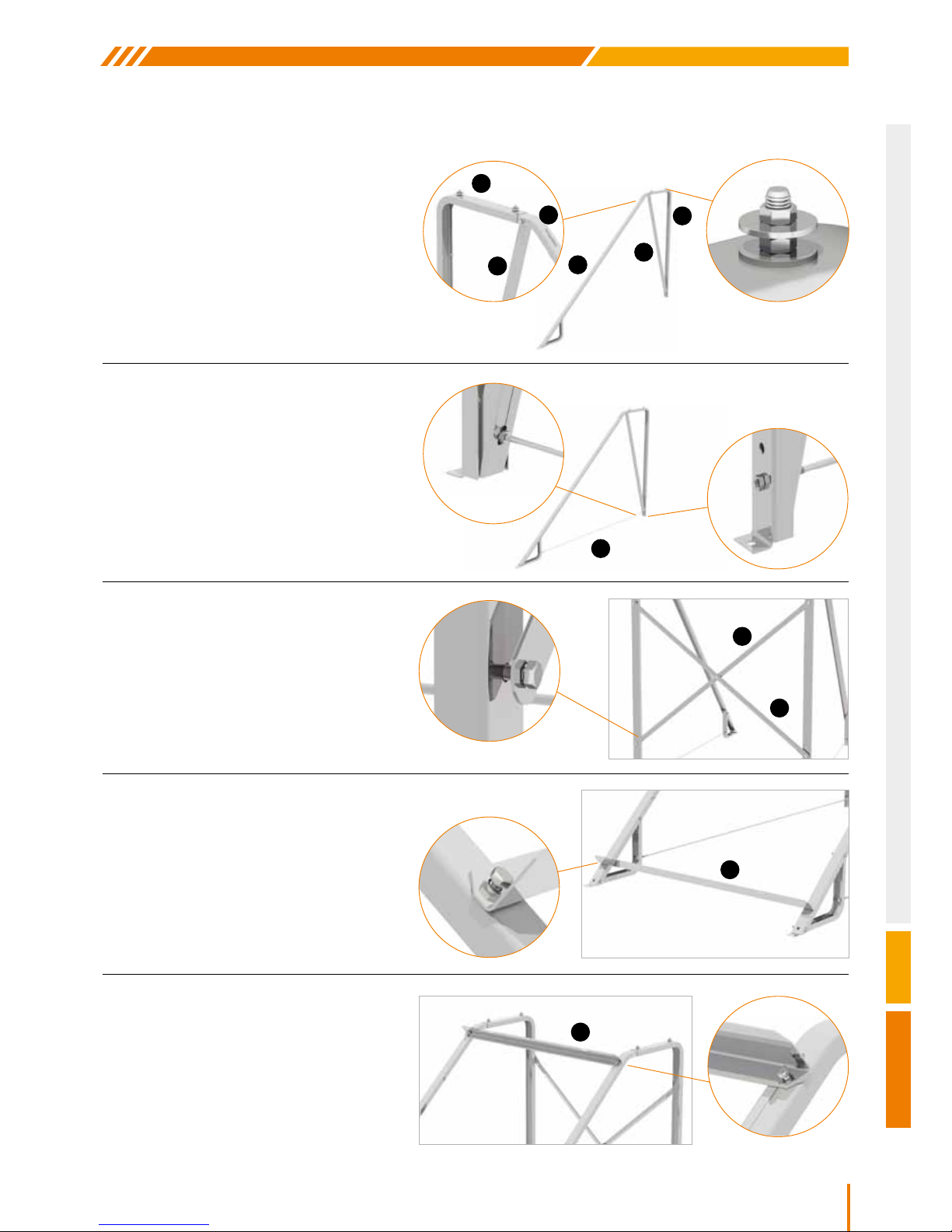
3. Parts 4 are placed crosswise,
but not tightened.
SUPPORT BASE ASSEMBLY ON A FLAT SURFACE
4. One part 5 is placed at the bottom
and tightened with M8x20 screws.
5. The second part 5 is placed at the top
without tightening the M8x20 screws
to the nuts.
SYSTEM WITH 1 COLLECTOR
1. Part 1 is screwed and tightened to part 2
using the M8x25 screws, the nuts and the
washers contained in the packaging. Part 6
(if contained in the packaging) is joined to
part 2 with the M8x50 screws.
The procedure is repeated for the other
pair of 1 and 2 parts.
2. Screw rod 3 is screwed and tightened
between 1 and 2, after is has been
passed through part 6 (if contained in
the packaging) using double M8 nuts.
The procedure is repeated for the other
pair of 1, 2 and 6 parts.
3
2
1
6
2
1
6
5
5
4
4
Page 22
22
Nobel Xilinakis D. & Co preserves the right to change all specications of the products and their accessories without prior notice
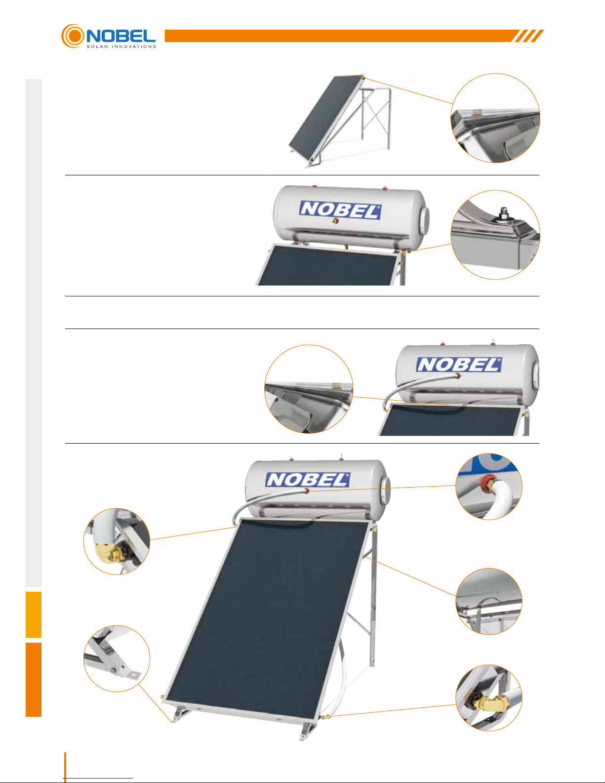
6. The collector is placed on the base with the
arrows pointing up, on the lower part 5, lifting
the upper part 5. The collector is screwed to
the M8x20 screws without tightening.
9. Center the collector and tighten the
M8x20 screws to parts 5, as well as
all other screws on the base.
8. Make sure the appliance is level and not at an angle using a spirit level.
7. The water tank is placed on the base with
the electrical components on the right
when looking at the solar water tank from
the front, and secured by tightening the
M8 nuts to the M8x25 screws, with which
we have joined 1 and 2 parts (STEP 1).
ΒΗΜΑ 12
ΒΗΜΑ 10
ΒΗΜΑ 13
ΒΗΜΑ 11
ΒΗΜΑ 17
Page 23

23
CLASSIC
Nobel Xilinakis D. & Co preserves the right to change all specications of the products and their accessories without prior notice
10. The DN16 INOX corner female union 3/4”, screwed horizontally and to the left to the water tank at the point
marked “JACKET INLET”.
11. The Ø22 x DN16 INOX corner union, is screwed on to the collector’s bottom right inlet with an upward direction
and an angle equal to the collector’s.
12. The second Ø22 x DN16 INOX corner union, is screwed on to the collector’s top left outlet with an upward
direction and according to the inclination angle of the collector.
13. The DN16 INOX female union 3/4”, is placed at the point marked “JACKET OUTLET” on the water tank.
14. Using the DN16 INOX exible connecting pipe the “JACKET OUTLET” (STEP 13) at the bottom of the water
tank is joined to the bottom right inlet of the collector (STEP 11), after rst having placed the relevant insulation
on the plastic pipe.
15. The DN16 INOX exible connecting pipe is then connected to the “JACKET INLET” (STEP 10) of the water tank
and to the upper left outlet of the collector (STEP 12), after rst placing the relevant insulation on the pipe.
NOTE: Make sure the length of the insulation is bigger that the pipe’s so that when the ttings are tightened in,
all the components will be covered.
16. Now all the ttings can be tightened.
17. The whole system then has to be properly oriented (See paragraph “GENERAL INSTALLATION RULES”).
18. Τhe base is secured using four Upat D10 and bolts (M8x60).
Page 24
24
Nobel Xilinakis D. & Co preserves the right to change all specications of the products and their accessories without prior notice
SUPPORT BASE ASSEMBLY ΟΝ Α FLAT SURFACE
SYSTEMS WITH 2 COLLECTORS
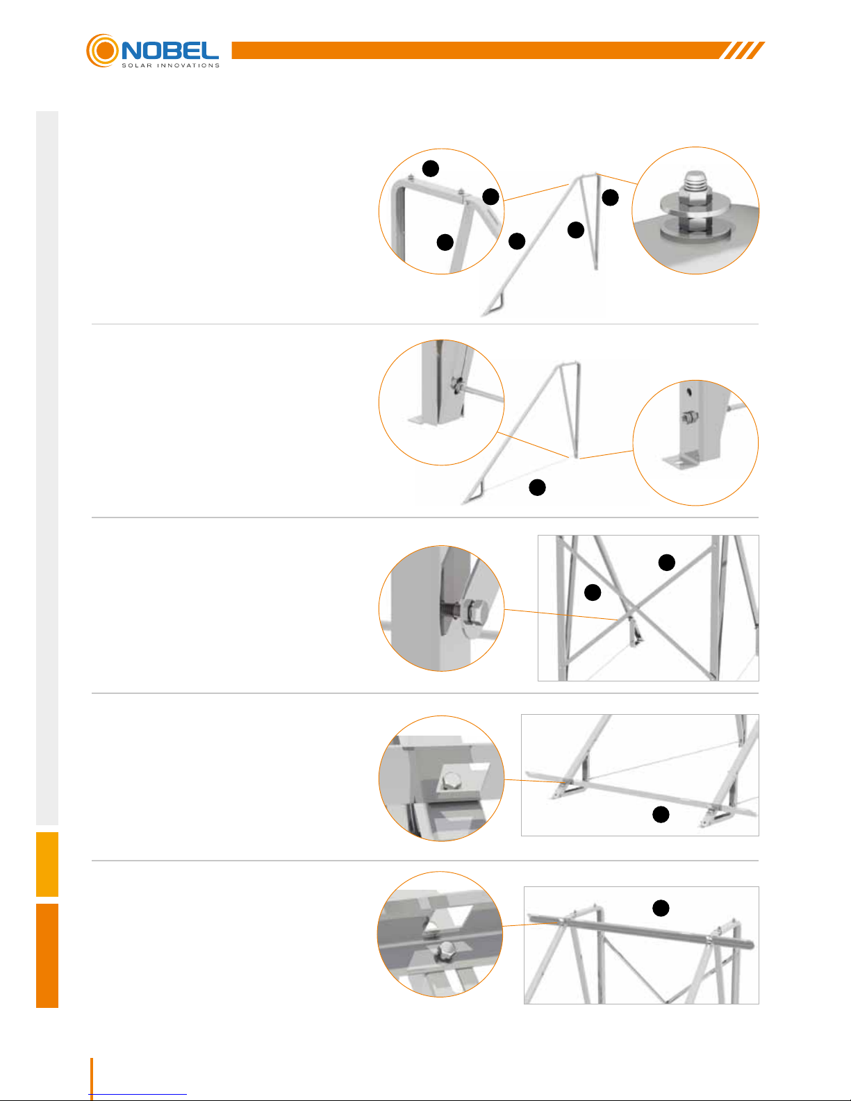
1. Part 1 is screwed and tightened to part 2
using the M8x25 screws, the nuts and the
washers contained in the packaging. Part
6 is joined to part 2 with the M8x50 screws.
(Parts 6 apply to the 200, 250 and 300 litre
types and not to the 160 litre type). The
procedure is repeated for the other pair of
1 and 2 parts.
5. The second part 5 is placed at the
top without tightening the M8x20
screws with the nuts.
3. Parts 4 are placed crosswise,
but not tightened.
2. Screw rod 3 is screwed and tightened
between 1 and 2, after is has been
passed through part 6 using double M8
nuts (parts 6 apply to the 200, 250 and
300 litre types and not to the 160 litre
one). The procedure is repeated for the
other pair of 1, 2 and 6 parts.
4. One part 5 is placed at the bottom
and tightened with M8x20 screws.
3
4
4
5
2
1
6
2
1
6
5
Page 25
25
CLASSIC
Nobel Xilinakis D. & Co preserves the right to change all specications of the products and their accessories without prior notice
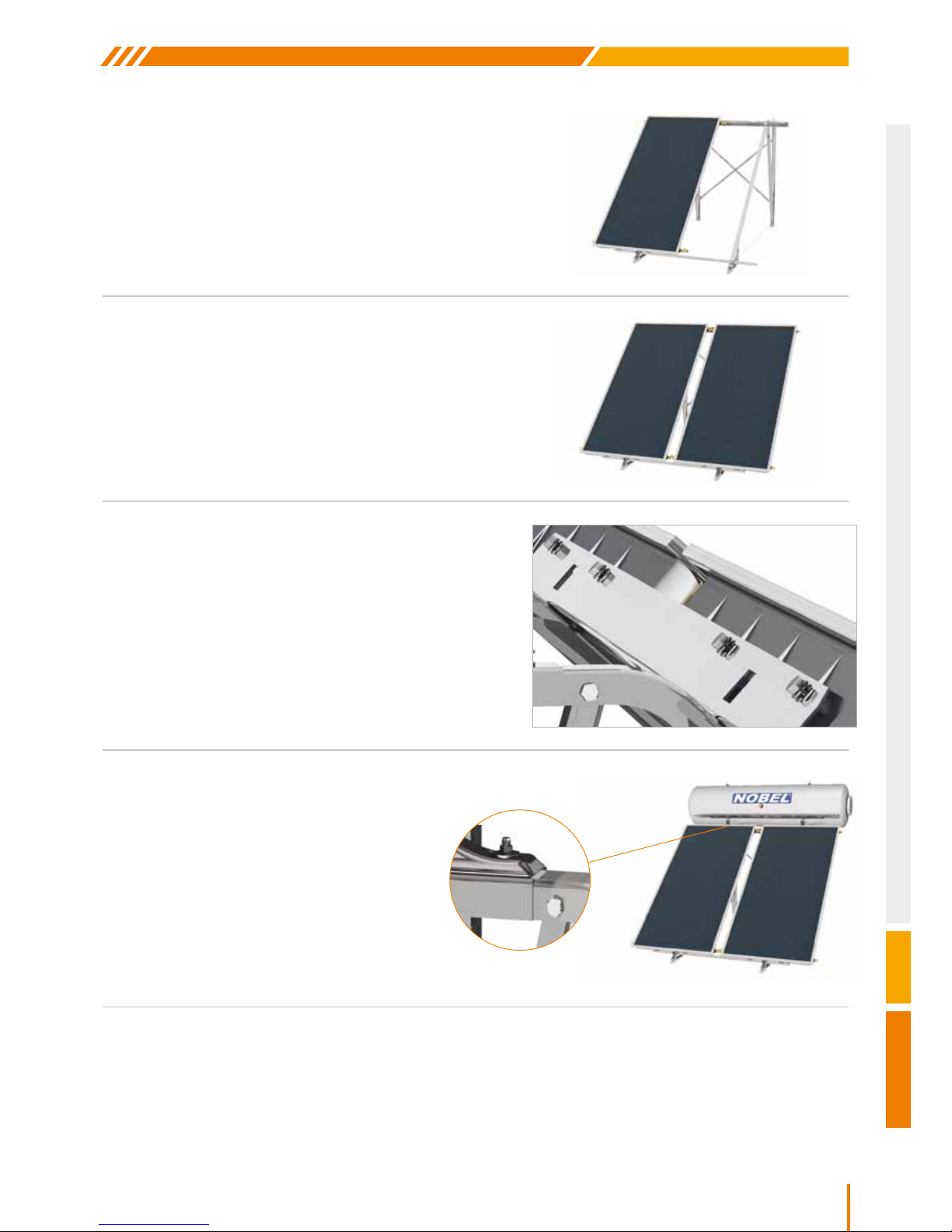
6. In case of two collectors, rst place the left one to the
bottom part 5 lifting the upper one. Place the screws
M8x20 with the support washers of the collector (4 for each
collector) without tightening them. Place the T-pieces Ø22 x
DN16 INOX x Ø22 unions at the edges of the collector.
8. The collectors are screwed with M8x20 screws
and washers onto parts 5 without tightening.
7. Join the second collector without tightening the union.
9. The water tank is placed on the base with
the electrical components on the right
when looking at the solar water tank from
the front, and secured by tightening the M8
nuts to the M8x25 screws, with which we
have joined 1 and 2 parts (STEP 1).
10. Center the collectors and tighten the M8x20 screws to parts 5, as well as all other screws on the base.
11. Make sure the appliance is level and not at an angle using a spirit level.
Page 26
26
Nobel Xilinakis D. & Co preserves the right to change all specications of the products and their accessories without prior notice
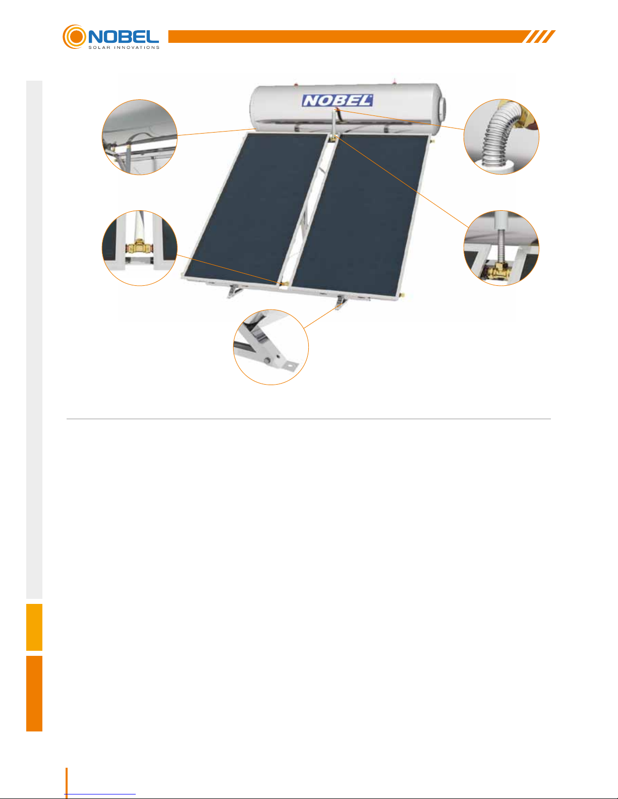
12. The female unions 3/4” x DN16 INOX are placed on the water tank at the points marked “JACKET INLET” (STEP
12a) and “JACKET OUTLET” (STEP 12b).
13. Using the exible connecting pipe DN16 INOX, the “JACKET OUTLET” (at the bottom of the water tank) is joined
to the T-piece at bottom inlet of the collectors (STEP 13a), after rst having placed the relevant insulation. The
exible connecting pipe DN16 INOX, is then connected to the “JACKET INLET” of the water tank and to the
T-piece at the top outlet of the collectors (STEP 13b), after rst placing the relevant insulation.
NOTE: Make sure the bottom T-piece is angled in the same way as the collectors, the top T-piece is vertical and
the length of the insulation is greater than that of the respective pipes’ so that when the ttings are tightened in,
all the components will be covered.
14. All the ttings and T-pieces are tightened.
15. The whole system then has to be properly oriented (See paragraph “GENERAL INSTALLATION RULES”).
16. Τhe base is secured using four Upat D10 and bolts (M8x60).
During the installation of the collector, make sure that the arrow points up.
ΒΗΜΑ 12b
ΒΗΜΑ 13a ΒΗΜΑ 13b
ΒΗΜΑ 16
ΒΗΜΑ 12a
Page 27
27
CLASSIC
Nobel Xilinakis D. & Co preserves the right to change all specications of the products and their accessories without prior notice
2
1
1
Α
Α
2
3
3
3
SUPPORT BASE ASSEMBLY ΟΝ ΑΝ INCLINED SURFACE
ATTENTION! After the installation check that the collectors surface has a tilt angle to the horizontal position of
geographical latitude ±5°.
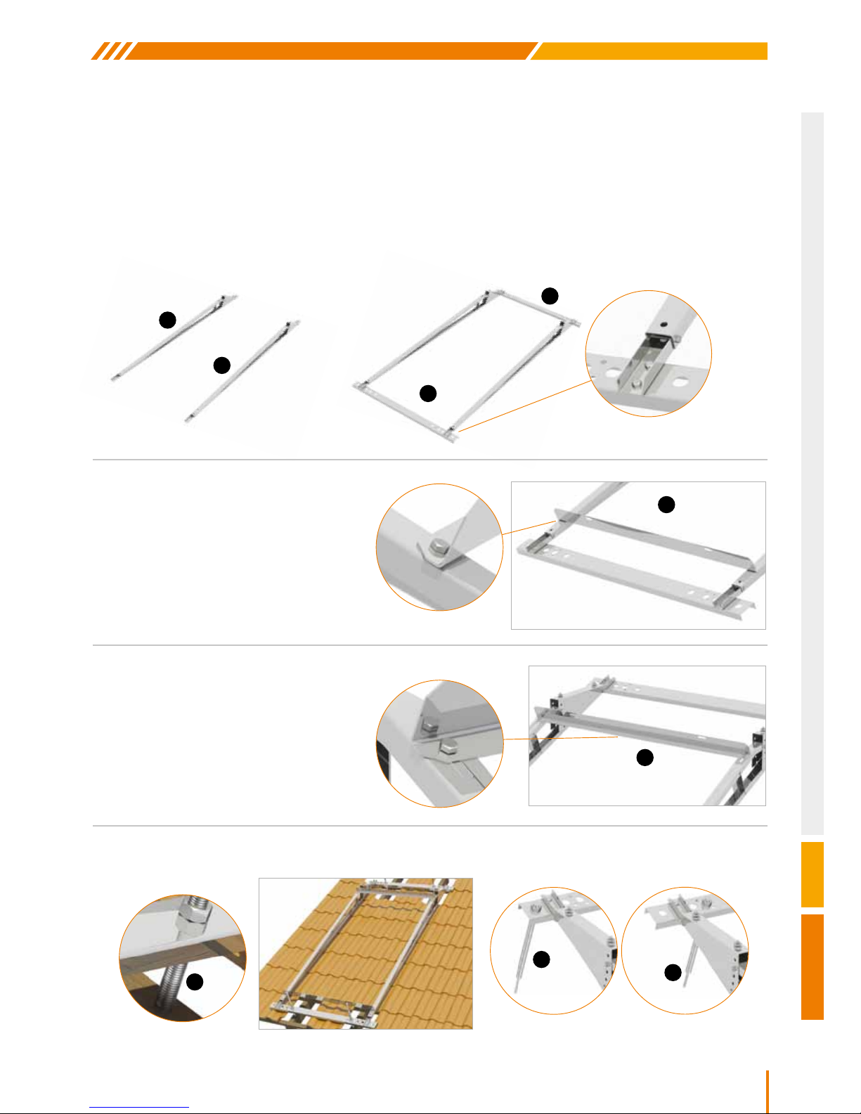
SYSTEMS WITH 1 COLLECTOR
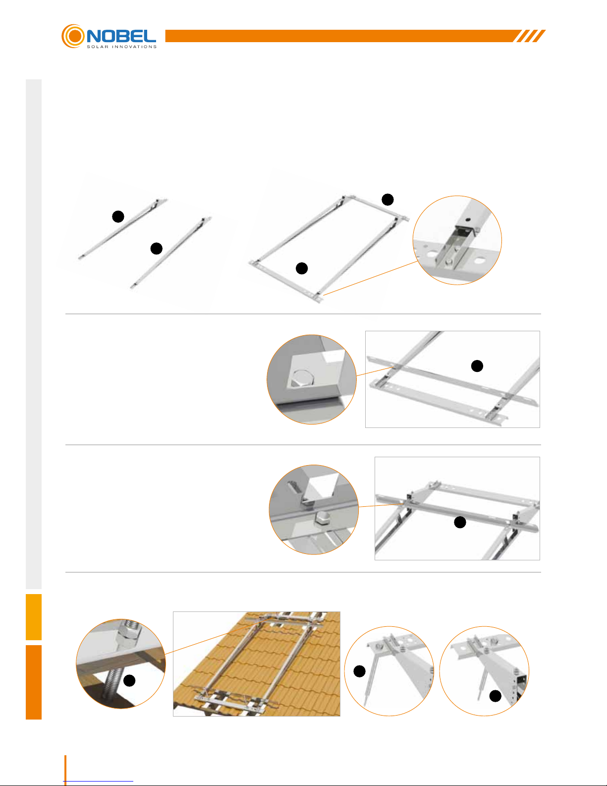
1. Parts 1 are screwed and tightened to parts A using the M8x20 screws, and the nuts contained in the packaging.
4. The four studs 3 are screwed to the respective appropriate holes in parts 1 and onto a solid internal beam of the
tilled roof.
2. One of the parts 2 is placed at the bottom
and tightened with M8x20 screws.
3. The second of the parts 2 is placed
at the top without tightening the
M8x20 screws with the nuts.
Page 28
28
Nobel Xilinakis D. & Co preserves the right to change all specications of the products and their accessories without prior notice
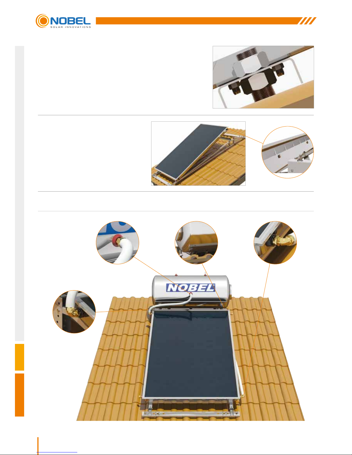
5. After angling as desired, the base is tightened
onto studs 3 with the M22 nuts and washers.
7. Using a spirit level the water tank bases 4 are leveled and the M8x60 screws are tightened.
6. The collector is placed on the base with
the arrows pointing up, on lower part
2, lifting upper part 2 and screwed with
the M8x20 screws onto parts 2 without
tightening.
ΒΗΜΑ 10
ΒΗΜΑ 12
ΒΗΜΑ 13 ΒΗΜΑ 11
Page 29
29
CLASSIC
Nobel Xilinakis D. & Co preserves the right to change all specications of the products and their accessories without prior notice
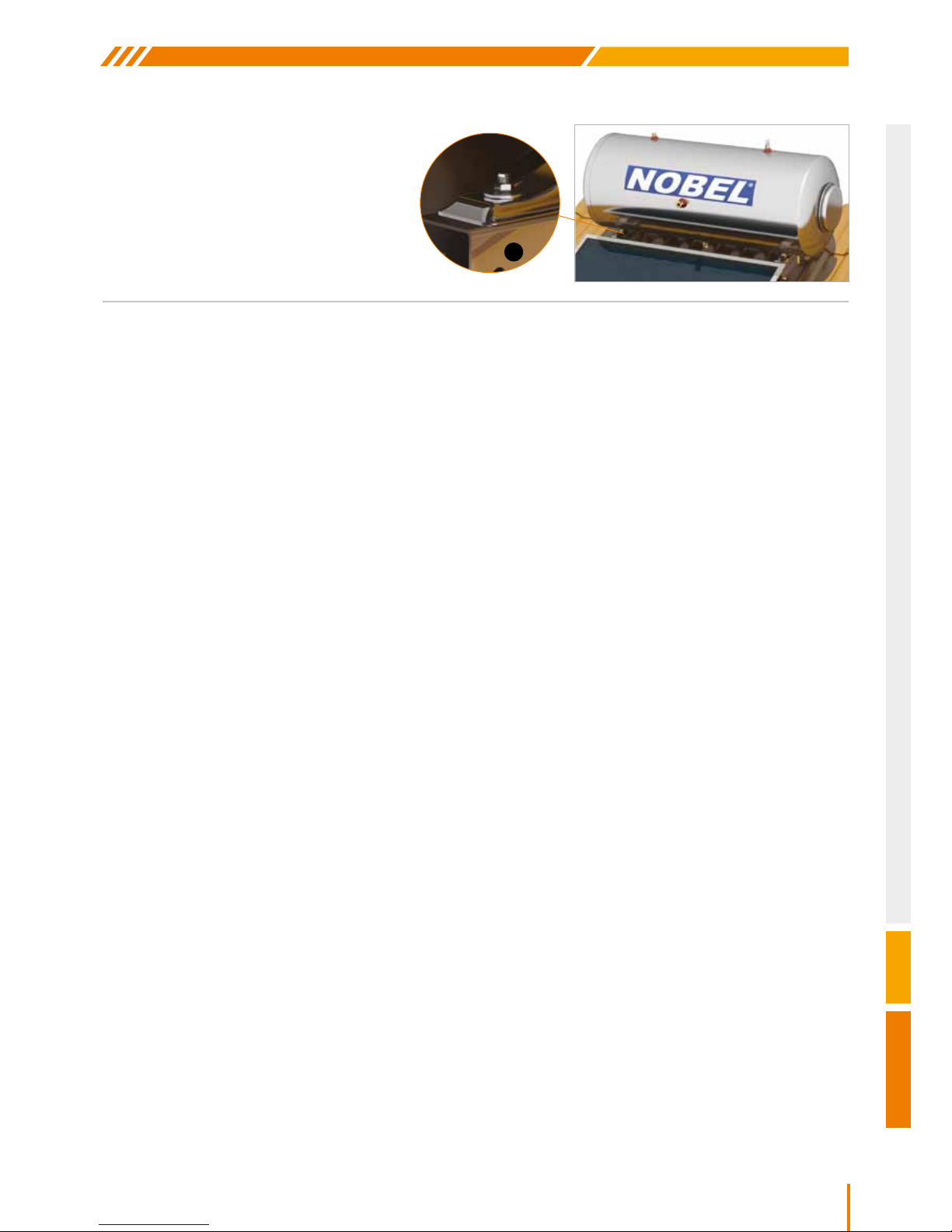
8. The water tank is placed on the bases 4
with the electrical components on the right
when looking at the solar water tank from
the front, and secured by tightening the
M8 nuts with the M8x25screws.
9. Center the collector and tighten the M8x20 screws to parts 2.
10. The corner female union 3/4” x DN16 INOX is screwed horizontally and to the left to the water tank at the point
marked “JACKET INLET”.
11. The corner union Ø22 x DN16 INOX is screwed on to the collector’s bottom right inlet with an upwards direction.
12. The second corner union Ø22 x DN16 INOX is screwed on to the collector’s top left outlet with an upwards
direction.
13. The second corner female union 3/4” x DN16 INOX is placed at the point marked “JACKET OUTLET” on the
water tank.
14. The exible connecting pipe DN16 INOX, the “JACKET OUTLET” (STEP 13) at the bottom of the water tank is
joined to the bottom right inlet of the collector (STEP 11), after rst having placed the relevant insulation on the pipe.
15. The exible connecting pipe DN16 INOX is then connected to the “JACKET INLET” (STEP 10) of the water tank
and to the upper left outlet of the collector (STEP 12) after rst placing the relevant insulation on the pipe. The
pipe must be angled upwards.
NOTE: Make sure the length of the insulation is greater than that of the pipes’ so that when the ttings are
tightened in, all the components will be covered.
16. All the ttings are tightened as well as the rest of the screws of the base.
4
Page 30
30
Nobel Xilinakis D. & Co preserves the right to change all specications of the products and their accessories without prior notice
1
1
Α
Α
3
3
3
2
2
SUPPORT BASE ASSEMBLY ΟΝ ΑΝ INCLINED SURFACE
ATTENTION! After the installation check that the collectors surface has a tilt angle to the horizontal position of
geographical latitude ±5°.
SYSTEMS WITH 2 COLLECTORS
1. Parts 1 are screwed and tightened to parts A using the M8x20 screws, and the nuts contained in the packaging.
4. The four studs 3 are screwed to the respective appropriate holes in parts 1 and onto a solid internal beam of the
tilled roof.
2. One of the parts 2 is placed at the bottom
and tightened with M8x20 screws.
3. The second of the parts 2 is placed
at the top without tightening the
M8x20 screws with the nuts.
Page 31
31
CLASSIC
Nobel Xilinakis D. & Co preserves the right to change all specications of the products and their accessories without prior notice
4
4
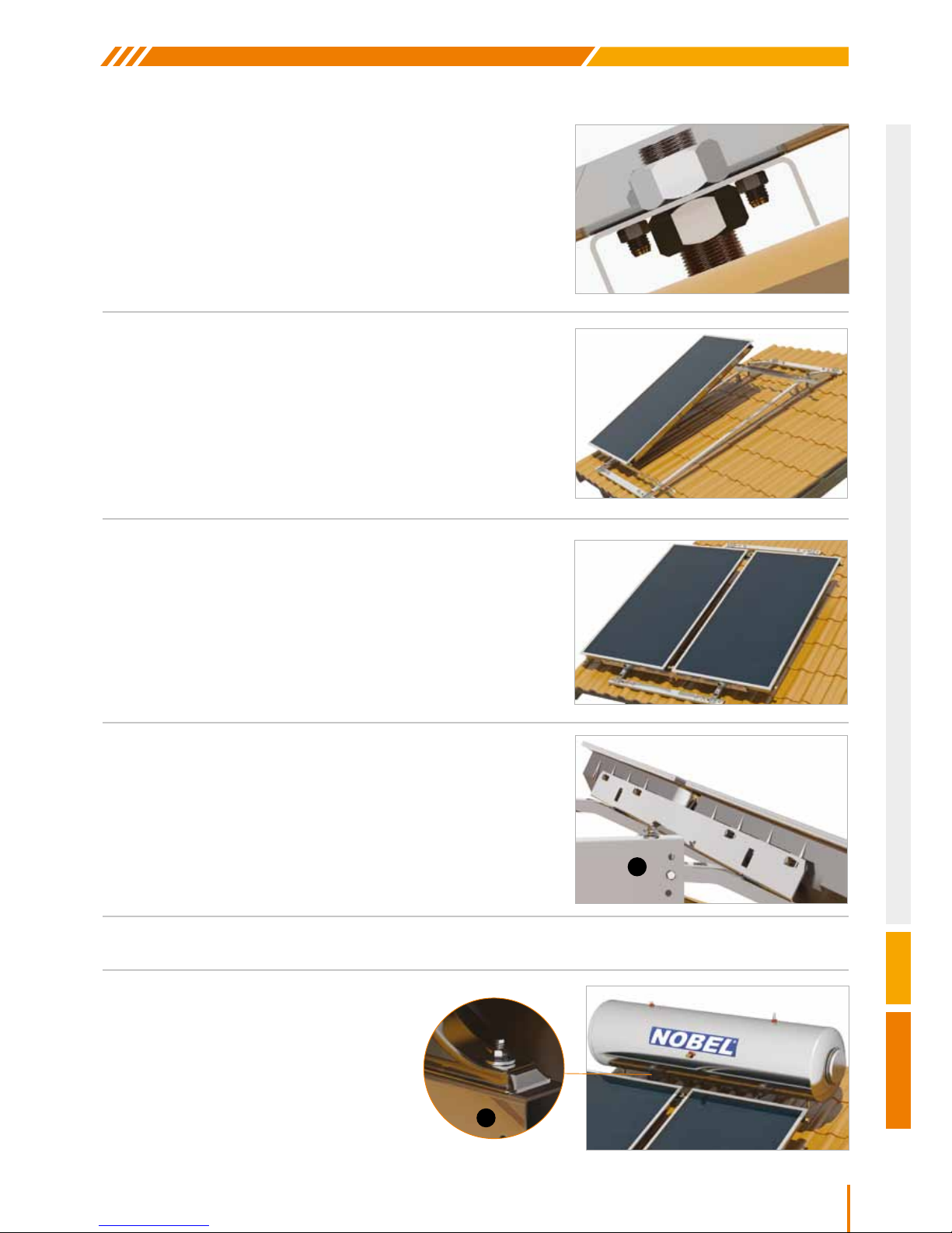
5. After angling as desired the base is tightened
onto studs 3 with the M22 nuts and washers.
10. The water tank is placed on the bases 4
with the electrical components on the right
when looking at the solar water tank from
the front, and secured by tightening the
M8 nuts with the M8x25 screws.
8. The collectors are screwed with M8x20 screws
and washers onto parts 2 without tightening.
9. Using a spirit level the water tank bases are leveled and the M8x60 screws are tightened.
6. In case of two collectors, rst place the left one to the
bottom part 5 lifting the upper one. Place the screws with
the support washers of the collector (4 for each collector)
without tightening them. Place the T-pieces Ø22 x DN16
INOX x Ø22 unions at the edges of the collector.
7. Join the second collector without tightening the union.
Page 32
32
Nobel Xilinakis D. & Co preserves the right to change all specications of the products and their accessories without prior notice
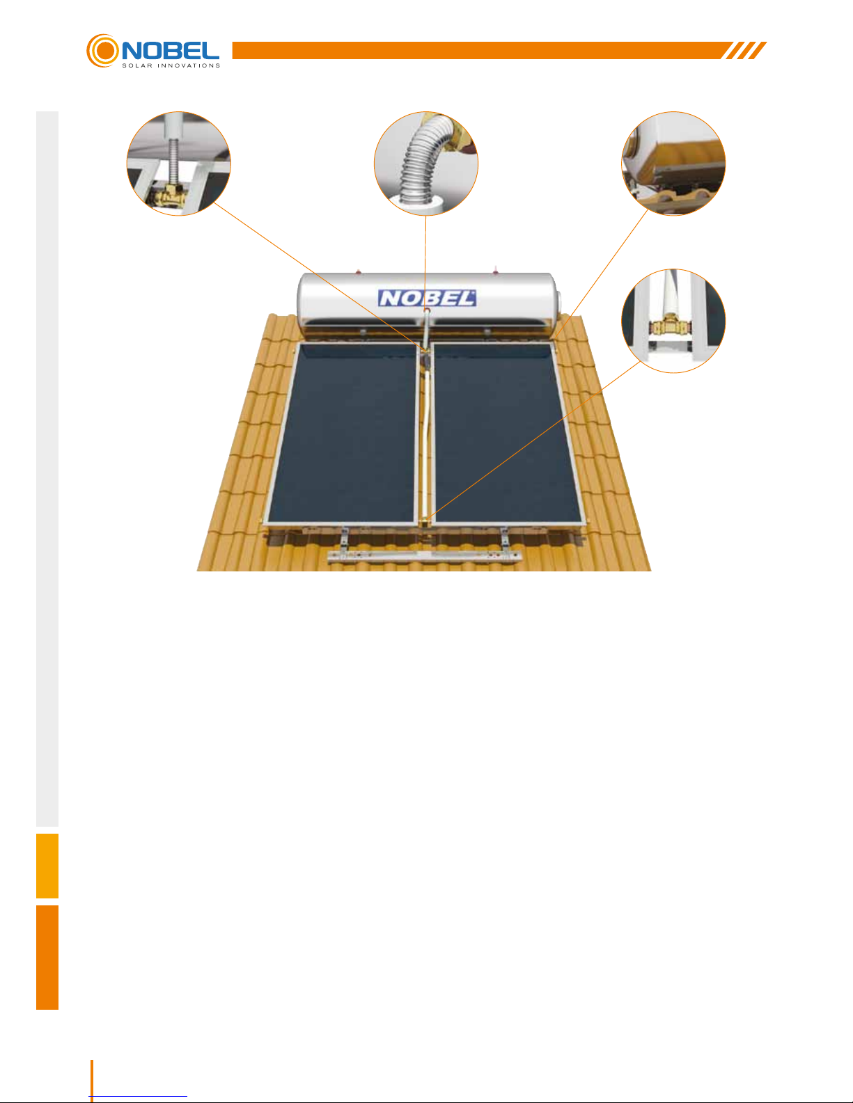
11. Center the collectors with the water tank and thighten the M8 x 20 screws to parts 2.
12. A female union 3/4” x DN16 INOX is screwed to the water tank at the point marked “JACKET INLET”.
13. A corner union 3/4” x DN16 INOX is placed at the point marked “JACKET OUTLET” (STEP 13a). Using the
exible connecting pipe x DN16 INOX, the “JACKET OUTLET” at the bottom of the water tank is joined to the
T-piece at the bottom inlet of the collectors (STEP 13b), after rst having placed the relevant insulation.
14. The exible connecting pipe x DN16 INOX is then connected to the “JACKET INLET” of the water tank and to the
T-piece at the upper outlet of the collectors (STEP 14) after rst placing the relevant insulation.
NOTE: Make sure the bottom T-piece is angled the same as the collectors, the top T-piece is vertical and the
length of the insulation is greater that the respective pipe’s so that when the ttings are tightened in will cover all
the components.
15. All the ttings and T-pieces are tightened.
16. Center the collectors and tighten the M8x20 screws to parts, as well as all other screws on the base.
ΒΗΜΑ 14 ΒΗΜΑ 12 ΒΗΜΑ 13a
ΒΗΜΑ 13b
Page 33
33
CLASSIC
Nobel Xilinakis D. & Co preserves the right to change all specications of the products and their accessories without prior notice
1. The antifreeze is diluted with clean water in a container and mixed until
it is fully dissolved. The closed circuit cannot be lled with antifreeze
unless it is rst diluted with water to a ratio of 1:1.
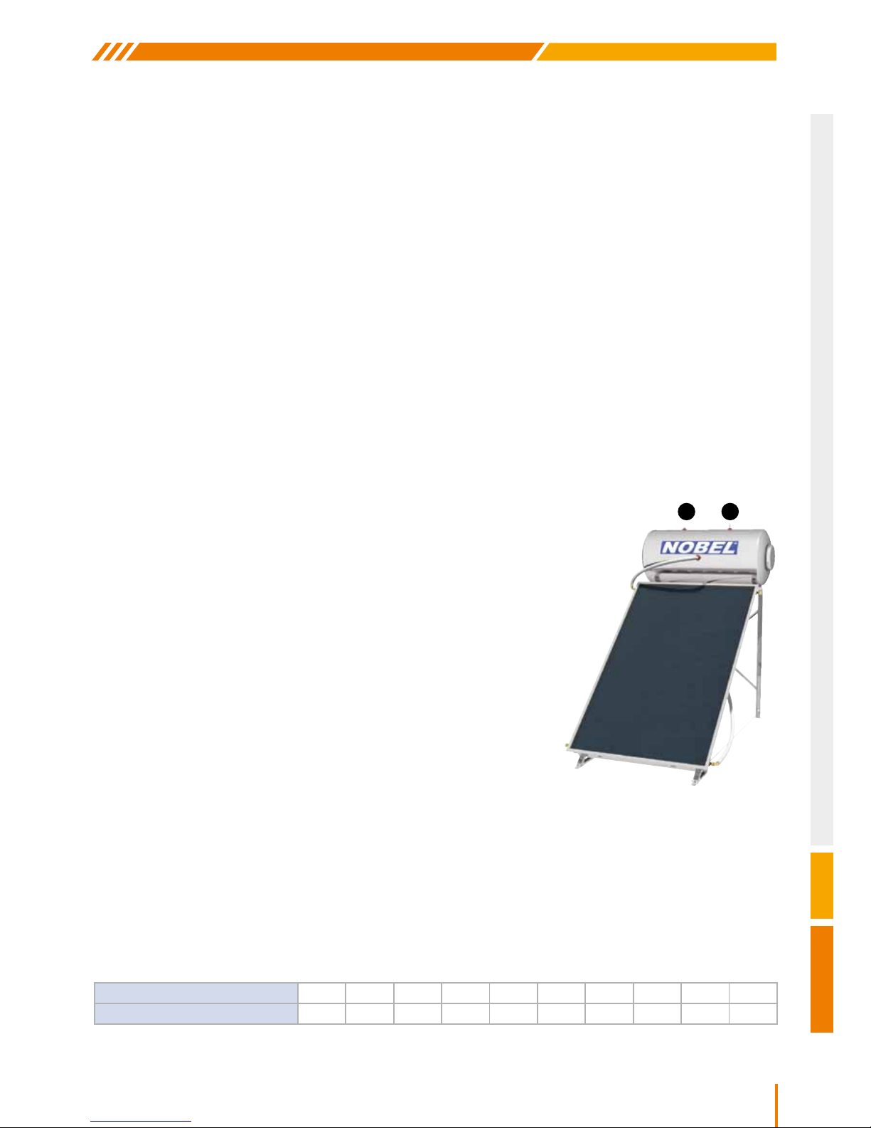
2. The solution is fed into the water tank from the top “CLOSED CIRCUIT
FILLING POINT” (2). Τhe “CLOSED CIRCUIT SAFETY VALVE
CONNECTION” (1) is kept open to ease the bleeding of the closed
circuit and is lled with water until full. Τhe lling should be done slowly
(so as to allow air bubbles to escape), and should continue until liquid
overows at the lling inlet.
3. The female 1/2” plug is placed on one pipe joint at point (2) and the
2.5 bar safety valve on the other at point (1).
4. The female 1/2” plug and the 3.5 bar safety valve are secured on the
respective water tank lling points.
5. The collectors are uncovered and the glass cleaned.
6. Following the completion of the installation, the appliance should be
left for 24 hours without any hot water being used so that the closed
circuit can go into operation.
7. Joint sealing. Check for leaks and make sure that all pipe joints to the collectors and the water tank, as well as
the cold and hot water pipes towards the system are properly insulated, in order to avoid thermal loss and protect
them from frost.
HYDRAULIC CONNECTION
CONNECTING THE SYSTEM WITH THE COLD AND HOT WATER MAINS
The “COLD WATER INLET” and “HOT WATER OUTLET” sockets colored blue and red respectively are located on
the side of the water storage tank.
ATTENTION! The connections to the hot and cold water pipes should be made with union nuts and not by soldering.
1. Onto the “COLD WATER INLET” the hot water safety valve is screwed rst, followed by a mini ball valve. The
cold water pipe is then connected to the ball valve with an insulated plastic pipe Ø15.
2. The “HOT WATER OUTLET” is then connected to the hot water pipe of the consumer network through an
insulated plastic pipe (Plastic pipes are recommended to minimize electro-corrosion).
3. Filling the water storage tank WITH WATER: With the ball valve and a hot water tap open, the water storage tank
is allowed to be lled with cold water. When water starts to run out of the tap, the water storage tank is full and
the hot water tap can be closed.
CLOSED LOOP FILLING
ATTENTION! Before starting to ll the closed loop with anti freeze liquid, the water storage tank has to be completely
lled with water.
ANTI FREEZE LIQUID is an advanced, propylene glycol based special product, designed and formulated in order
to ensure effective heat transfer properties at high or low temperatures. It is non-toxic and provides protection up
to -37°C (solution 55% v/v with water). It is especially designed to provide excellent anticorrosion properties. In
aquacius solutions anti freeze liquid offers protection according to the extent of dilution as per in the table below:
21
PERCENTAGE %
5 10 15 20 25 30 40 45 50 55
TEMPERATURE °C
-2 -4 -6 -8 -11 -15 -19 -24 -30 -37
Page 34
34
Nobel Xilinakis D. & Co preserves the right to change all specications of the products and their accessories without prior notice
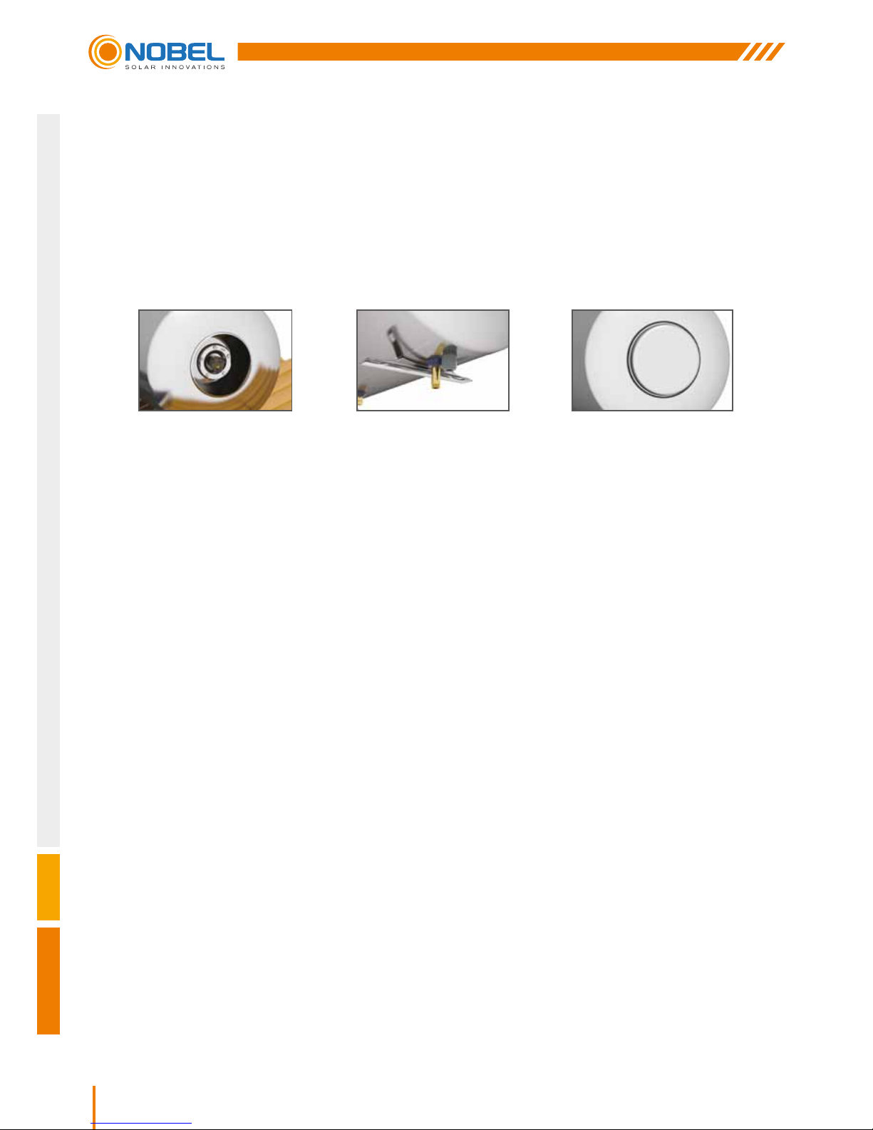
1. Remove the screws from the protection ap which covers the electrical components (Img.1).
2. A 3x4mm
2
section electrical cable (for a 4kW heating element) is required to connect the heating element to the
mains.
3. Pass the end of the cable through the gland and towards the electrical components (Img. 2).
4. Connect the black wire (phase) to the connector L and the blue wire (neutral) to the connector N on the thermostat.
Connect the yellow wire (earthing) to the small M4 screw on the heating element marked with the ground symbol
(Drawing 1).
5. The thermostat has been connected to the heating element at the factory. Adjust the thermostat to 60°C.
ATTENTION! The thermostat should be well tted at the heating element (Drawing 1)
6. Close the cover of the electrical components (Img 3)
7. Switch off the central mains switch.
8. Connect the other end of the cable to the electrical board using a bipolar disconnection switch with a minimum
distance between contacts of at least 3mm. The circuit breaker’s rating must be suitable for the heating element
in use.
Caution! A safety relay against electrical shock is absolutely necessary.
NOTE: The daily hot water (40°C) load which can be met by the system without any contribution from solar energy
(that is, only through 24h 2kW heating element operation), according to 5.10 of EN 12976-2:2000, is this of maximum
1000lt.
ELECTRICAL CONNECTION
DESCRIPTION OF ELECTRICAL COMPONENTS (heating element - thermostat - accessories)
ELECTRICAL DIAGRAM - General rules
The electrical installation of the solar water heater should be carried out by a qualied electrician and in
accordance with the national regulations in force and the rules and conditions that apply to the building
where the installation is taking place.
The heating element must not be switched on when there is no water in the water storage tank.
In such case the heating element warranty does not apply.
NOTE: The heating element’s rating depends on local regulations of the country of destination.
Img. 1
Img. 2
Img. 3
Page 35
35
CLASSIC
Nobel Xilinakis D. & Co preserves the right to change all specications of the products and their accessories without prior notice
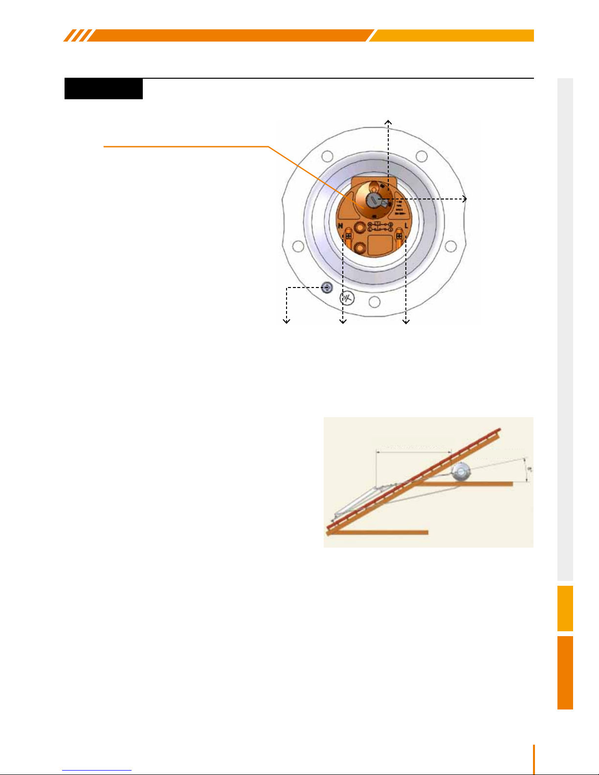
Drawing 1
For the system’s optimum operation using natural
circulation, the maximum and minimum distances and
angles for the pipes must be respected. The maximum
distance between the collector outlet and the water
storage tank inlet must not exceed 3m.
The angle of the pipe joining these 2 points must not be
less than 8°.
Thermostat
Temperature
Regulator
(40-80°C)
L= PhaseN=NeutralEarthing
HEATING
ELEMENT
SYSTEM INSTALLATION ON A TILED ROOF WITH THE WATER STORAGE
TANK UNDER THE ROOF (Natural circulation operation)
CONNECTING THE HEAT EXCHANGER
This concerns triple action solar systems equipped with a large exchange surface coil, for the alternative heating of
the water using the central heating system.The coil is placed in front of the electric parts.
HYDRAULIC CONNECTION
The central heating system to which the solar system is to be connected must be equipped with:
y Solar system isolation valves.
y Automatic relief valves at the highest point of the pipes, which must be very well insulated.
y Suitably angled connecting pipes so as not to trap air in the circuit.
y The connections to the coil heat exchanger must be made through unions.
ELECTRICAL COMPONENTS (Heating Element - Thermostat)
MAX. DISTANCE 3m
MIN. ANGLE 8°
THERMOSTAT AUTOMATIC
AUXILIARY THERMOELECTRIC
FUSE F
This is tripped when the water storage
tank’s internal temperature exceeds
95°Cand shuts down the thermostat, to
protect the appliance form overheating.
RESETTING THE
THERMOELECTRIC FUSE F
Rotate the temperature regulator until
the button of the thermoelectric fuse F
appears and press it. Once the fuse
has been reset to its normal operating
position (pressed in), the thermostat
can operate again.
Page 36
36
Nobel Xilinakis D. & Co preserves the right to change all specications of the products and their accessories without prior notice
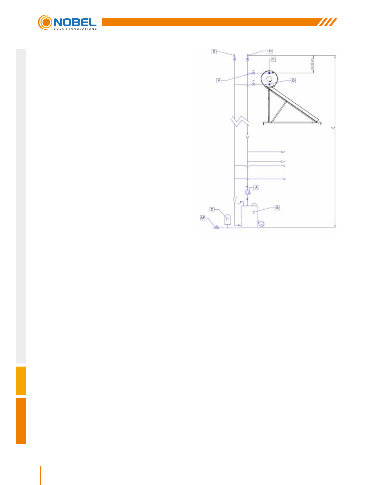
Specically: To connect the coil heat exchangers of the solar
system to the central system water storage tank, follow the
STEPs below:
1. Place unions on the inlet E and on the outlet O of the
exchanger.
2. Place a ball valve of suitable V diameter.
3. Place automatic relief valves D on both the water supply
and return lines of the central heating water storage tank
at least 20cm higher than the exchanger inlet.
4. Insulate all connecting piping with at least 9mm of
insulating material.
5. Adjust the automatic lling valve AF, 1/2 bar above the
static height H (e.g. for a height of 15m, it should be set
to 2 bar).
6. Fill the system with water and check for leaks.
POSSIBLE PROBLEMS - SOLUTIONS
THE SOLAR WATER STORAGE TANK DOES NOT SUPPLY A SATISFACTORY AMOUNT OF HOT
WATER BY SOLAR POWER
In this case follow these STEPs:
If after all the above checks you are still not satised with your solar system’s performance, then please contact your
local representative or the company’s technical department.
1. Take the weather conditions into consideration.
2. Avoid large hot water consumption during the night.
3. Check if your needs in hot water have increased
and cannot be covered by the system’s capacity.
4. Make sure your solar water heater is not shaded by
any kind of obstacles,
5. Check that the system is leveled.
6. Check carefully all connections for tightness and
tighten or replace any connections that are not
tight.
7. Check the building’s piping and taps for the
possibility of slow leakage.
8. Make sure the hot water supply is not mixing with a
cold water supply.
9. Make sure the connecting pipes are not kinked.
10. Check the level of the antifreeze liquid and top up if
necessary.
11. Make sure there is no trapped air in the water
storage tank or the collectors.
A. Circulator
B. Central heating water storage tank
C. Expansion tank
Page 37
37
CLASSIC
Nobel Xilinakis D. & Co preserves the right to change all specications of the products and their accessories without prior notice
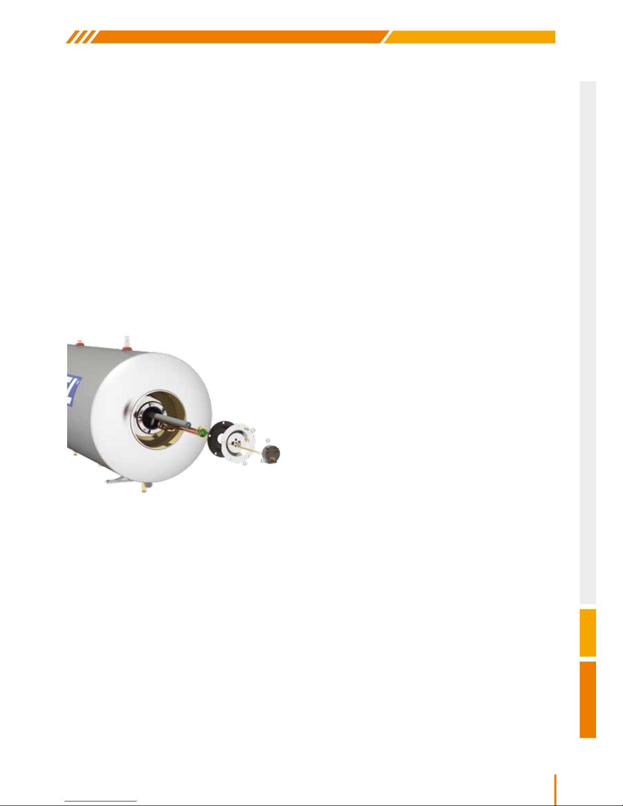
SERVICE - MAINTENANCE
Your solar water heater should be serviced every two years by an authorized representative or a company technician.
These periodic checks are necessary for the solar water heater’ s warranty to apply. The inspection concerns the
whole system and more specically:
THE SOLAR WATER STORAGE TANK DOES NOT SUPPLY HOT WATER WHEN USING
THE ELECTRICAL HEATING ELEMENT
The following tasks must be carried out only by a qualied electrician.
1. Shut down the electrical supply and open the
electrical components’ cover.
2. Check the cable connection between the thermostat
and the heating element.
3. Check the temperature at which the thermostat
is set, so that it is not lower than that needed for
consumption.
4. Check the heating element.
5. Check the central electrical connection.
6. Switch on the electrical current and measure the
voltage at the heating element’s terminals.
7. Check the thermostat’s thermoelectric fuse F, which
must be pressed in. If it is not, rotate the thermostat’s
regulator until the button of the thermoelectric fuse
F appears. Press this. Once it has been reset, the
thermostat can operate once again.
Especially for the replacement of the anode bar follow these steps:
1. Shut down the electrical supply.
2. Empty the water from the water storage tank.
3. Remove the electrical component’s cover.
4. Disconnect the three electrical wires.
5. Remove the electrical heating element by removing
the M8 screws.
6. Remove the old magnesium bar from the heating
element’s ange.
7. Screw in the new magnesium.
8. Replace the heating element with the rubber seal.
9. Unscrew the external magnesium cap located on
the water storage tank’s right side.
10. Replace the sacricial anode with a new
Ø22x300mm on the cap and screw back into place.
11. Open the water supply and a hot water tap until the
water storage tank lls up.
12. Check for water leaks.
13. Reconnect the electrical components at their
designated positions.
14. Check that the thermostat is securely clipped to the
heating element.
15. Replace the electrical component’s cover.
16. Reconnect the electrical supply.
1. Flange
2. Safety valve
3. Heating element - thermostat
4. Connection ttings
5. Piping
6. Insulation - seals
7. Transparent cover (solar glass)
8. Supporting system
9. Replacement of anode and
checking the closed loop’s liquid.
It is recommended that the water
storage tank is cleaned of mineral
deposits and sludge every ve
years.
Page 38

38
Nobel Xilinakis D. & Co preserves the right to change all specications of the products and their accessories without prior notice
ATTENTION!
y Any intervention - work on the solar water heater must be carried out only by specialized technicians and where
electrical components are concerned, only by qualied and licensed electricians.
y All solar water heater service data must be entered on the respective chart on the warranty document (term of
warranty).
y In areas where extreme weather conditions are common (hail storms, storms, tornadoes, etc.) it is recommended
that the appliance is insured.
POST INSTALLATION INSTRUCTIONS
Before using the system make a nal check. Open all the valves and check for any kind of leakage. Repeat the
inspection after 30 minutes. Check if the system is lled with water and antifreeze uid according to the company’s
instructions. In case of any failure condition a specialized technician should be called in.
Following its installation, the solar water storage tank needs about 2 days in order to achieve its maximum efciency.
For this reason it is recommended that there is no hot water consumption during the rst two days following installation,
even if there is ample sunshine.
A basic periodic maintenance will assure the long life and high efciency of the solar water heater.
y It is recommended that the appliance is inspected in situ according to the instructions stated in the guarantee
twice a year and checked for possible damage (breaking) of the collectors’ glass, leaks in the connecting piping to
the mains and to the consumption system, inspection of the pipe insulation and cleaning of the glass.
y If the collectors’ glass is broken, it should be replaced immediately.
y It is recommended that the glass is washed at an hour of low sunlight to avoid damages due to expansion-
contraction, due to temperature changes.
y If the ttings are worn (screws, pugs, piping, etc), these should be replaced at the owner’s cost.
y The level of antifreeze in the closed circuit must be checked annually (as it could need toping up), to ensure the
efcient operation.
y In cases where there is to be no use of hot water for long periods of time (e.g. during the summer holidays), it
is recommended that the collector surface is covered with an opaque cover in order to avoid the building up of
high temperatures, which could trip the thermoelectric fuse of the thermostat and cut the electrical circuit. (See
paragraph “RESETTING THE THERMOELECTRIC FUSE F”).
y During the build-up of high pressure in the thermal tank, it is possible that the safety valve will open and water will
run out. This is a normal function that protects the water storage tank from high pressures. If the mains pressure
exceeds 4 atm., it is necessary to add a pressure reducer - expansion tank.
y Do not switch on the electrical heating element in the following cases:
Α) When the mains water supply has been cut
Β) When the connecting pipes have frozen and there is no water ow from the water storage tank to the taps.
Caution! Place taps with thermostatic regulation up to 38°C for hot water use to prevent burns which may be caused
by the high temperature water in the solar water heater.
We remain at you disposal for any further information you may need.
We can assure you that you have made the best choice.
Thank you for choosing our products.
Page 39
39
CLASSIC
Nobel Xilinakis D. & Co preserves the right to change all specications of the products and their accessories without prior notice
CHECK LIST
INSTRUCTIONS FOR THE INSTALLER
After the installation is complete, the installer, with the help of the check list below has to check all of the points which
are noted and mark in the relevant column with a √.
LIST CHECK
COLLECTORS AND EXTERNAL PIPING
Is the installation and the xing of the support base according to the instructions and local regulations?
Is there an ideal location and facing of the collectors?
Is there humidity inside the collectors?
Are the hydraulic connections of the collectors correct?
Has there been good UV protection on the thermal insulation?
Is the piping properly insulated?
Has the installment on the roof been done according to the local regulations?
HYDRAULIC CONNECTIONS
Are there any leaks in the closed circuit, the connections, or in the tube heat exchanger ?
Are the safety valves installed properly?
Does a mixing valve of hot / cold water exist?
ELECTRICAL CONNECTION
Is the electric resistance connected properly? (if it exists)
Has the electric connection been done according to the local regulations? (insulation, grounding, etc...)
GENERAL
Was the guarantee properly lled in and given to the client?
Were the instructions of use given to the client?
Was the proper selection of the model made according to the needs of the client?
Was the client informed of other options for the production of hot water?
Distributor Data
Full name.....................................................................
Address........................................................................
Telephone.....................................................................
Installer Data
Full name.....................................................................
Address........................................................................
Telephone.....................................................................
Page 40
40
Nobel Xilinakis D. & Co preserves the right to change all specications of the products and their accessories without prior notice
METEOROLOGICAL DATA OF EUROPEAN CITIES
Meteorological data of European cities
Jan. Feb. Mar. April May June July Aug. Sep. Oct. Nov. Dec. Year
Total global radiation [kWh/mÇ] 24 42,1 74,5 112 137 151 160 138 95,1 59,1 32,4 19,5 1046
Total diffuse radiation [kWh/mÇ] 17,1 24,8 48,1 70,9 80,5 88,4 83,4 79,2 54,7 35,8 20,3 13,8 616,7
Average ambient temperature [ÆC] 3,6 4,2 6,4 9,3 12,9 15,9 18 17,8 15,3 11,4 6,9 4,6 10,6
Wind speed [m/s] 4,2 4,3 4,4 4,3 3,9 3,8 3,5 3,3 3,4 3,4 4 3,9 3,9
Monthly values, annual total
Town: PARIS Country: FR
Height: 78 meters above sea level
Longitude: -2,45 Æ latitude: 48,97 Æ
Paris
Jan. Feb. Mar. April May June July Aug. Sep. Oct. Nov. Dec. Year
Total global radiation [kWh/mÇ] 45,4 61,8 93,7 126 167 192 202 158 109 63,3 36 32,7 1287
Total diffuse radiation [kWh/mÇ] 27,7 37,5 61,1 79,2 92,1 93,2 79,2 88,5 56,1 43,8 26,1 22,4 707
Average ambient temperature [ÆC] 4,9 6,5 10 13 15,7 20,6 24,2 23,6 19,8 14 8,9 5,6 13,9
Wind speed [m/s] - - - - - - - - - - - - -
Monthly values, annual total
Town: Madrid Country: ES
Height: 667 meters above sea level
Longitude: 3,68 Æ latitude: 40,42 Æ
Madrid
Jan. Feb. Mar. April May June July Aug. Sep. Oct. Nov. Dec. Year
Total global radiation [kWh/mÇ] 29,6 46,5 86,2 126 163 172 183 153 109 70,8 34,8 22,8 1197
Total diffuse radiation [kWh/mÇ] 19,5 27,9 47,2 70,4 86 93,4 89,7 79,5 53 38,5 23 15,6 643,5
Average ambient temperature [ÆC] -1,2 1,3 5,8 11 15,9 19 20,6 20 16,1 10,7 5 0,7 10,4
Wind speed [m/s] 3 3,2 3,4 3,3 2,9 2,9 2,7 2,5 2,6 2,6 2,9 2,9 2,9
Monthly values, annual total
Town: Budapest (Kispest) Country: HU
Height: 112 meters above sea level
Longitude: -18,10 Æ latitude: 47,43 Æ
Budapest
Jan. Feb. Mar. April May June July Aug. Sep. Oct. Nov. Dec. Year
Total global radiation [kWh/mÇ] 56,6 72,6 119 154 192 202 216 187 143 103 61,2 48,4 1556
Total diffuse radiation [kWh/mÇ] 30,1 36 57 72,1 87,7 85,1 80,8 65 61,2 42 30,8 24,2 671,9
Average ambient temperature [ÆC] 6,2 7,1 9,7 12,3 16,5 20,6 23,7 23,3 19,6 15,4 11,5 7,6 14,5
Wind speed [m/s] - - - - - - - - - - - - -
Monthly values, annual total
Town: Roma Ciampino Country: IT
Height: 121 meters above sea level
Longitude: -12,60 Æ latitude: 41,80 Æ
Roma
Jan. Feb. Mar. April May June July Aug. Sep. Oct. Nov. Dec. Year
Total global radiation [kWh/mÇ] 76,9 100 147 172 212 226 227 205 168 134 96 75,5 1839
Total diffuse radiation [kWh/mÇ] 36,3 45,9 55,9 75,1 79,9 64,7 66,7 71,2 51,8 47,2 34,6 32 661,2
Average ambient temperature [ÆC] 13,1 13,1 14 16,4 19,3 22,5 25,1 26,3 25,7 23 18,6 15,1 19,3
Wind speed [m/s] 2,1 1,5 2,1 5,6 4,6 4,6 5,1 4,6 4,1 2,1 2,1 1,4 3,3
Monthly values, annual total
Town: Limassol Country: ZY
Height: 0 meters above sea level
Longitude: -33,00 Æ latitude: 34,67 Æ
Limassol
Page 41
41
CLASSIC
Nobel Xilinakis D. & Co preserves the right to change all specications of the products and their accessories without prior notice
NOTES
Page 42
42
Nobel Xilinakis D. & Co preserves the right to change all specications of the products and their accessories without prior notice
NOTES
Page 43

Page 44

www.nobel.gr
XILINAKIS D. & Co
SOLAR & ELECTRIC WATER HEATING SYSTEMS INDUSTRY
EXPORT DEPARTMENT: 25 I. Nika, 136 73 Αcharnes - Greece | Τel.: +30 210 2478677 - Fax: +30 210 2407185
HEADQUARTERS: 23 Nerantzoulas, 136 77 Αcharnes - Greece | Τel.: +30 210 2404051 - Fax: +30 210 2443444
e-mail: [email protected]
V.1 - JUN. 2012
 Loading...