

Page 1
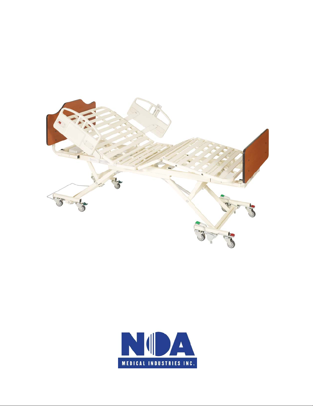
OPERATION AND MAINTENANCE MANUAL
NOA Medical Industries Inc.
NOA Light
1070001BEI
Manual Number 1100072_5 Save these instructions ©2008 NOA Medical Industries, Inc.
Page 2

T
ABLE OF CONTENTS
…
.
…
.
…
…
.
…
.
…
…
…
.
…
.
…
…
Warnings………………………………………………………………………………………………………………………
Reducing the Risk of Entrapment……………………………………………………………………………………….….
Steps to Prevent Bed Fires………………………………………………………………………………………….………
Specifications and Conditions……………………………………………………………………………………….……
Physical Specifications……..………………………………………………………………………….…….……
Locating Your Serial Number…………………………………………………….………………..……………
Environmental Conditions………………………………..……………………………………...…………….….
Electrical Specifications………………….…………………………………………………………………..….
Installation………………………………………………………………….…………………………………………..……..
Installing the Head and Foot Boards……………………………………………………………………………
Securing the Power Cord………………………………………………………………………………………….
Installing the Corner Mattress Retainers…………….………………………………………………………….
Locating and Connecting the Pendant (Handset) Control……………………………………..………………
Bed Transport……………………………….……………………………………………………………………
Bed Operation…………………………………………………………………………… …………………………….…….
Bed Positioning……………………………………………………………………………………………………
Accessories and Options..…………………………………………………………...……………………………………
3
5
5
6
6
6
6
6
7
7
7
8
9
9
9
9
10
Foot Board Control……………….…………….…………………………………………………………………
Servicing……………………………………………………………………………………………………….…………..…
Troubleshooting…………..………………………………………………………………….…………….….……
MCL Control Box Socket Identification…………………………………………………..………….………..….
Steps for Isolating Electrical Problems…………………………………………………………..………………
Bed Diagram……………..……………………………………………………..………………………................
Parts List…………………………..………………………………………………………………....……………
Maintenance and Cleaning ……………….………………………………………………..…………..…………………..
Cleaning and Disinfecting the Bed……………….………………….…………..……..……………………..…
Periodic Inspection………………...……………….………………………….…..……..………………………
Limited Warranty……………………………………………………………….…………………………………
Copyright ©2008 NOA Medical Industries, Inc. All rights reserved. Publisher reserves the right to make dimension or specification changes, or
deletions, consistent with design trends, product improvements, or for reasons beyond our control. Publisher makes no warranties with respect
to the accuracy or completeness of the contents of this manual. “Elite Riser
NOA Medical Industries, Inc.; other trademarks used in this document are property of their respective trademark holders.
®
”, “V Riser”, “AP Riser”, “Twin Riser”, and “Onyx” are trademarks of
Manual Number 1100072_5 Save these instructions Page 2 of 14
10
10
10
11
11
12
12
13
13
13
14
Page 3

SPECIAL NOTES
WARNINGS/CAUTION NOTICES in this manual apply to hazards or unsafe practices, which could result in
personal injury and/or property damage.
NOTICE
The information in this document is subject to change without notice.
Check all parts for shipping damage before using. DO NOT USE IF DAMAGED. ONLY USE AUTHENTIC NOA
REPLACEMENT PARTS. Contact NOA Medical Industries Inc. Customer Service 1 (636) 239-7600 and the freight
carrier for further instruction.
This electric bed has been engineered to provide reliable operation.
This bed has been thoroughly tested and inspected prior to shipment.
WARNINGS
DO NOT OPERATE THIS EQUIPMENT WITHOUT FIRST READING AND UNDERSTANDING THIS MANUAL. IF
YOU ARE UNABLE TO UNDERSTAND THE WARNINGS, CAUTIONS, OR INSTRUCTIONS, CONTACT A
HEALTH CARE PROFESSIONAL OR A QUALIFIED TECHNICIAN BEFORE USING THIS EQUIPMENT.
OTHERWISE INJURY OR DAMAGE MAY RESULT.
The correct bed height when unattended is based on the resident’s knee to floo r height, mobility, and cognitive
level. For residents with good mobility and cognition, the top of mattress should be at a height so that the
resident’s feet are flat on the floor and the angle between the thighs and calves is 90 degrees. Bed height and
the resident’s abilities must be evaluated by a medical professional.
If the resident’s physical or mental state may lead to entrapment, the sleep deck should be left in the flat
position when unattended.
Do not use near explosive gases.
Possible fire hazard when used with oxygen administering equipment other than nasal or masked type.
When using nasal or masked type administering equipment, oxygen or air tubing MUST
properly to ensure tubing does not become entangled, kinked, or severed during normal operation of the bed.
Close supervision by a caregiver is necessary when this product is used near CHILDREN OR PEOPLE WITH
DISABILITIES.
NEVER PERMIT ANYONE UNDER THE BED AT ANY TIME.
When operating/moving the bed always ensure that the individual utilizing the bed is positioned properly within
the confines of the bed. DO NOT
performing these functions.
After installation and before use, make sure all attaching hardware is securely tightened.
Pendant cord must be routed and secured properly to ensure cord does not become entangled and damaged
during normal operation of the bed.
let any extremities protrude over the side or between the rails when
be routed and secured
Manual Number 1100072_5 Save these instructions Page 3 of 14
Page 4

WARNINGS
(continued)
Keep all moving parts free from obstruction (i.e. blankets/sheets, pads, tubing, wiring, etc.) which may get
tangled around the bed, side rails, or legs during operation of the bed.
Beds are equipped with locking casters. Casters should be locked at all times except when moving the b ed.
The mattress should be a hospital type mattress to allow for proper bed articulation. The mattress must be
properly sized to meet entrapment zone dimensional guidelines published by the FDA.
These side rails are not for pediatric use.
The side rails are NOT
professional should be consulted for other means of safe restraint.
When using safety side rails, if excessive side pressure is exerted on them they can be deformed or broken. Do
not use side rails as handles to move the bed.
Never permit more than one person in/on the bed at any time.
Body weight should be evenly distributed over the surface of the bed. The bed weight capacity is 450 pounds.
This is the total weight of the resident, mattress, bedding, head and foot boards, side rails and any other
accessories.
The bed is provided with an additional safety feature of a protective earth ground. The electrical cord should
only be plugged into a GROUNDED 110/120V outlet. DO NOT ALTER THE PROVIDED PLUG. If the plug
does not fit the existing outlet, a licensed electrician should install a correct outlet. Never operate the bed if it
has a damaged cord or plug.
Unplug the power cord when performing any maintenance on the bed.
Do not open any actuator, pendant, or control box. If these units are opened the warranty is voided.
The Safety Lock provides the resident with a stable and secure bed, providing easy access in and out of the
bed. Check that the Safety Lock is engaged and that the bed is solidly in place before leaving the bed
unattended or before attempting resident transfers into or out of the bed.
The Safety Lock is not intended to be used on a sloping floor or building access ramp. Use of the Safety Lock
on a sloping floor or building access ramp could result in injury or death.
The Safety Lock should be locked at all times except when the bed is being moved.
For maximum resident safety, caster locks (if available) should be used in addition to the Safety Lock system.
Turn off cellular phones or similar electronic devices when in close proximity to the bed. These devices may
cause unintentional movement of the bed or affect bed performance in unpredictable ways. Do not use ra dio
frequency generating devices or devices that generate electromechanical electromagnetic interference in close
proximity to the bed. If you do not understand the dangers of electromagnetic interference contact a qualified
technician.
Contact a qualified technician before using High Frequency medical equipment near the bed. Only a qualified
technician should route High Frequency cables on or near the b ed.
Manual Number 1100072_5 Save these instructions Page 4 of 14
intended and may NOT be used as a restraint. If necessary, a physician or healthcare
Page 5

REDUCING THE RISK OF ENTRAPMENT
The Hospital Bed Safety Workgroup (HBSW) in partnership with the FDA has recognized p otential entrapment
zones in hospital bed systems and has developed dimensional guidan ce to reduce the risk of entrapment. The FDA
considers the term “hospital bed system” to encompass the bed frame and its components, including the mattress,
bed side rails, head and foot boards, and any accessories to the bed.
The entrapment zones involve the relationship of components controlled by the healthcare facility or individual u ser.
Compliance to the dimensional guidelines for reducing the risk of entrapment is primarily the responsibility of the
healthcare facility or the individual user.
Anyone having any involvement with hospital bed systems should review and understand the FDA guidelines.
These guidelines, entitled “Hospital Bed System Dimensional and Assessment Guidance to Reduce Entrapment Guidance for Industry and FDA Staff,” are available at the FDA website.
STEPS TO PREVENT BED FIRES
Inspect the bed’s power cord for damage.
Connect the power cord directly into a wall-mounted outlet that is in good working order, with no cracks or chips.
The plug should fit tightly into the outlet. The ground pin should be intact and secure.
Do not connect the bed’s power cord to an extension cord or to a multiple-outlet strip.
Do not cover any power cord with a rug. Heat may build up or the cord may be damaged.
Inspect the floor beneath the bed for buildup of dust and lint. Ask housekeeping to clean if necessary.
Inspect the resident’s bed controls, looking for signs of damage where liquids co uld leak in.
Test the bed and its controls, including resident lockout features, to ensure that the bed can move freely in both
directions without damaging any cords.
Check monitors and other resident equipment for signs of overheating or physica l damage.
Keep linens and clothes away from power sources.
Tell maintenance staff about any unusual sounds, burning odors, or unusual movement of a bed.
If you suspect overheating, follow your facility’s policy for fire safety and get the resident to a safe area if
necessary.
Manual Number 1100072_5 Save these instructions Page 5 of 14
Page 6
SPECIFICATIONS AND CONDITIONS
Note: All dimensions and weights are approximate unless otherwi se note d.
Physical Specifications
Sleep Deck Width 35" Safe Working Load**: 450 lbs.
Width w/Side Rails 40"
Sleep Deck Length 80"
Overall Bed Length* 84.5"
Weight 220 lbs.
Deck Height Range: 8.5" - 25"
Maximum Back Angle: 60 degrees
Maximum Hip to Knee Angle: 40 degrees
*O.A.L. includes both head and foot boards.
**The Safe Working Load is the total weight, including the resident, mattress, bedding, head and foot boards, side
rails, and other accessories evenly distributed on the sleep deck.
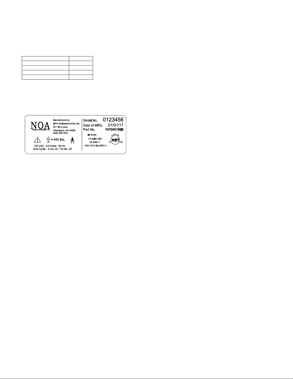
Locating Your Serial Number
The serial number label is located at the foot end of the bed,
under the mattress support deck, on the bed frame.
Please have the serial number and model of the bed
available when calling Customer Service 1(636) 239-7600.
Environmental Conditions Electrical Specifications
Ambient temperature range of 50F to 104F (10°C to 40°C)
Relative
Atmospheric
Control Box and
Actuators
Protected against dust and
humidity range of 30% to 75%
pressure range of 20.6 to 31.3 Inches of Hg.
Pendants
- IPX0
- IP54
splashing water
.
Power: 110/120 V.A.C.
Frequency: 60
Current
Duty
Cycle: 10% Max.
Hz
Rating: 5.0 Amps
(2 min. on/ 18 min. off)
Manual Number 1100072_5 Save these instructions Page 6 of 14
Page 7
INSTALLATION
Required Tools
(1) - #3 Phillips Head Screwdriver
Hardware Bag Contents
(8) - ¼ - 20 x 1.5” Machine Screws
(8) - ¼ - 20 Insert Cap Nuts
(1) - Adjustable Cable Clamp
(1) - #10-12 x ¾ Wood Screw
Upon receipt of your new bed, carefully inspect the bed and accessory components for any damage received in transit.
Notify the NOA Customer Service at 1 (636) 239-7600 immediately if any product or component has been damaged or is
missing from your shipment.
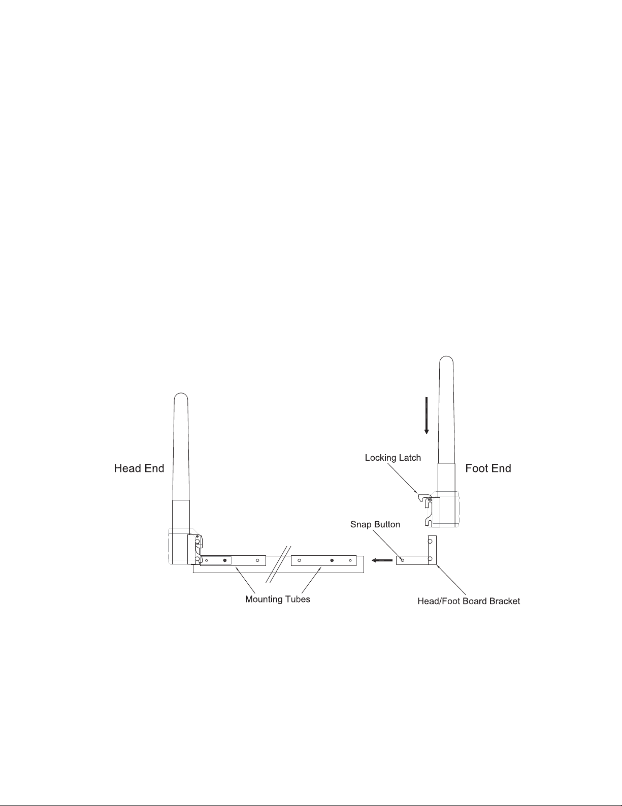
Installing the Head and Foot Boards
On large orders, beds are shipped with transport legs inserted in the foot board mounting tubes. Remove and discard
these legs and replace with head/foot board brackets. Insert brackets into the mounting tubes until snap buttons align in
the middle holes as indicated below. Ensure that snap buttons are seated in the proper holes prior to bed use.
locking latches and slide head and foot boards down onto the brackets. Release the latches to lock.
Lift the
Securing the Power Cord
Approximately 8 feet of exposed power cord is provided with the bed. A cable tie has been supplied so that excess
cord can be maintained and secured to the back of the head board. When securing the power cord, ensure that an
adequate loose length is maintained to allow for the full range of motion of the bed.
Manual Number 1100072_5 Save these instructions Page 7 of 14
Page 8
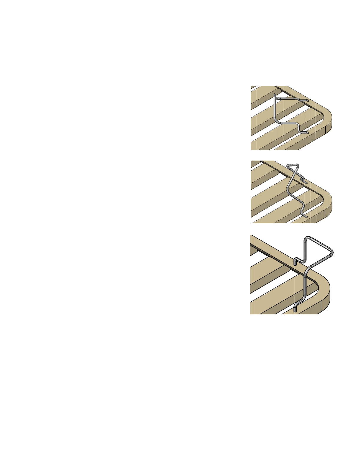
Installing the Corner Mattress Retainers
Corner Mattress Retainers (PN 3040025) should be installed at each corner of the bed to assist in maintaining proper
alignment of the mattress during bed use. In order for the retainers to be effective, beds should be used in
conjunction with a hospital grade mattress designed to allow for bed articulation. The mattress should be 6” thick with
a width and length conforming to the sleep deck size. Mattress retainers should be installed prior to installation of any
deck mounted side rails or assist bars.
1. Locate (2) ¼” holes at each bed corner in the outer
angle of the head and foot deck. Insert each leg of the
Mattress Retainer.
2. With the leg of each side of the Mattress Retainer
positioned in the ¼” holes, rotate the Retainer towards
the corner of the bed while slowly inserting the legs
further into the holes.
3. When fully rotated, press the Mattress Retainer into
position and then place the mattress on the rib-deck
sleep surface. Check that all corners of the mattress
are within the Retainers. A slightly compressed fit is
desired.
Ensure that the Retainers hold the mattress securely to prevent mattress slippage during head and foot deck
articulation.
Install accessory components as per their instructions.
Verify that there are no gaps between the mattress, head and foot boards, side rails, or any other accessories
wide enough to entrap a resident’s head, neck, or body.
obtained from the U.S. Food and Drug Administration Center for Devices and Radiological Health web site.
Your bed is ready for use. The bed should be located and casters locked while the bed is in its lowest position.
Adequate spacing must be maintained between the wall and the bed to prevent damage to the bed or walls whil e
raising or lowering the bed. Check to be sure that vertical movement of bed does not interfere with the power cord or
plug.
Manual Number 1100072_5 Save these instructions Page 8 of 14
Addition al information regarding bed entrapment may be
Page 9
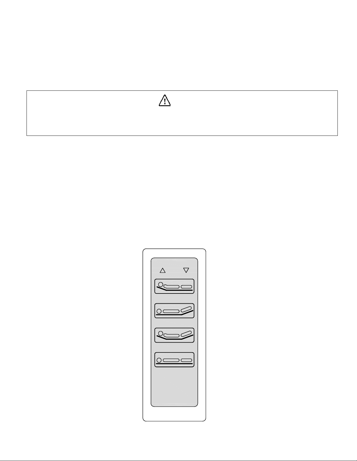
Bed Transport:
The bed features a rolling base that allows it to be rolled or locked at any bed height. In order to lock the bed, activate
the brakes located on the casters at the foot and head of the bed. To roll the bed, disengage brakes. Activating
caster brakes does not disengage bed functions.
Caution
If casters are not locked swivel and wheel rotation can allow for bed motion with little or no resistance.
This can result in loss of balance, fall, and personal injury. Ensure that the casters are locked
to prevent any bed movement during resident transfer and/or treatment.
BED OPERATION
Bed Positioning
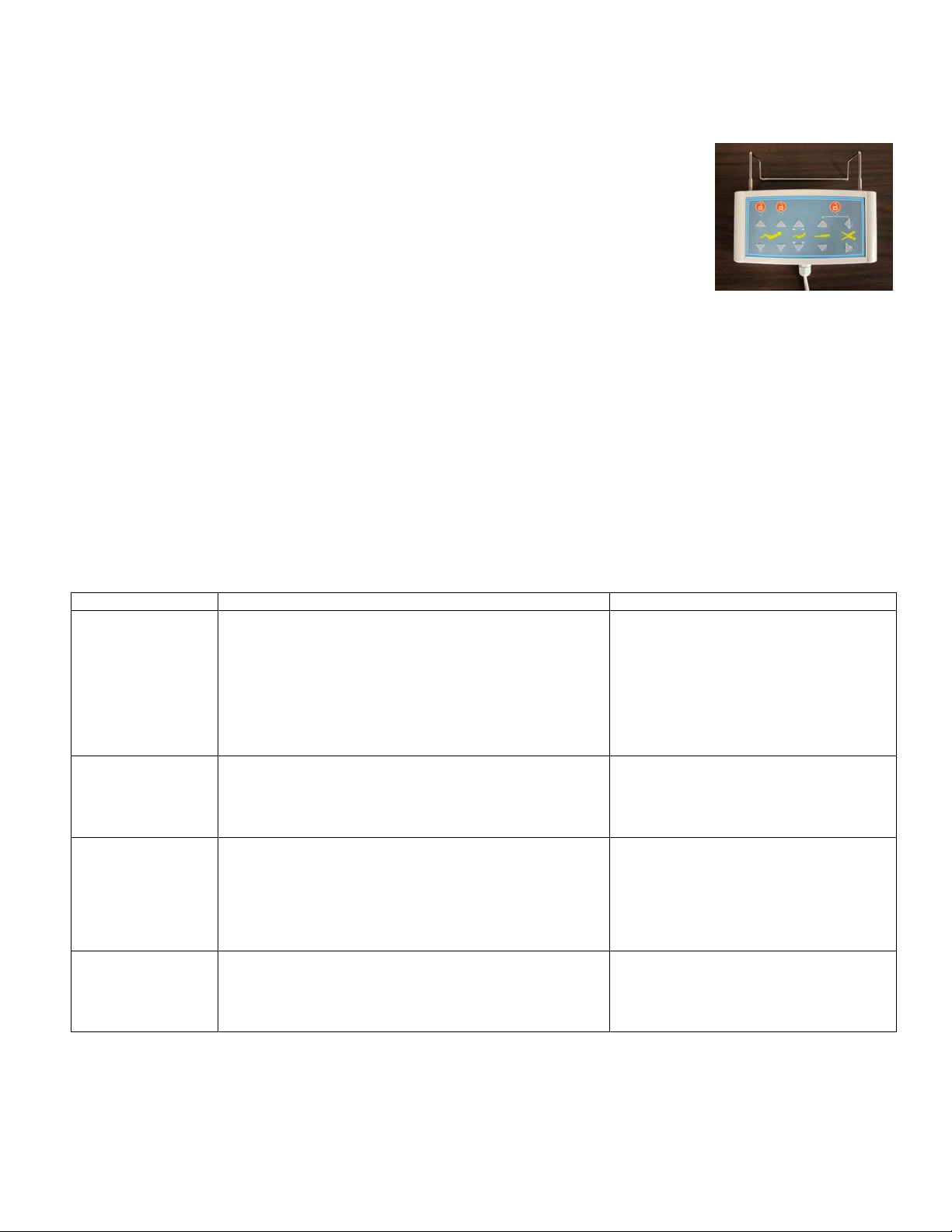
Bed functions are operated with an 8 button pendant (4040117). Button functions on the handheld pendant control are
clearly identified with universal icons. The hand control is provided with an attached bracket for suspending the control
from side rails or bed ends. PRIOR TO RAISING OR LOWERING THE BED AND/OR SIDE RAILS, CHECK TO
ENSURE THAT THE CORD FOR THE PENDANT CONTROL HAS NOT BECOME ENTANGLED IN BED PARTS.
THE CORD SHOULD BE KEPT CLEAR OF MOVING PARTS AT ALL TIMES.
Head Up Head Down
Foot Up Foot Down
Auto Contour Up Auto Contour Down
Hi/Lo Up Hi/Lo Down
Manual Number 1100072_5 Save these instructions Page 9 of 14
Page 10
ACCESSORIES AND OPTIONS
Optional Footboard Control
An optional Lock Out Footboard Control with Sub Acute
functions is available (PN 7540043).
Connecting the Optional Footboard Control Cable
Footboard Control
Connect one end of the Footboard Control Cable to the Footboard Control. Connect the other end of the Footboard
Control Cable to the designated hole in the Control Box.
SERVICING
Troubleshooting
SYMPTOM POSSIBLE CAUSE(s) ACTION
No Power
Actuators operate,
but the wrong
movement occurs
One or more
actuators do not
function
Bed is not level
when operating
Hi/Low functions
1. Bed is not plugged into A/C power.
2. Cut/damaged power cord.
3. Loose plug for pendant. Cut/damaged pendant cord.
4. Actuator plug not connected.
1. Cut/damaged pendant cord.
1. Loose or unplugged connection of actuator cord to
control box.
2. Cut/damaged actuator cord.
3. Defective actuator.
4. Defective control box.
1. Bed bumped a wall or encountered other obstruction
causing misalignment of actuators.
2. Bed being operated in the mid-range loaded at one end.
1. Check plug to receptacle.
2. Check power cord for damage.
3. Check pendant cord for damage.
4. Check actuator connection to control
box. Inspect actuator cord for
damage.
1. Inspect pendant cord for damage.
1. Check actuator plug to control box.
2. Inspect actuator cord for damage.
3. Replace actuator.
4. Replace control box.
1. Run bed to full up or full down position.
2. Run bed to full up or full down position.
Manual Number 1100072_5 Save these instructions Page 10 of 14
Page 11
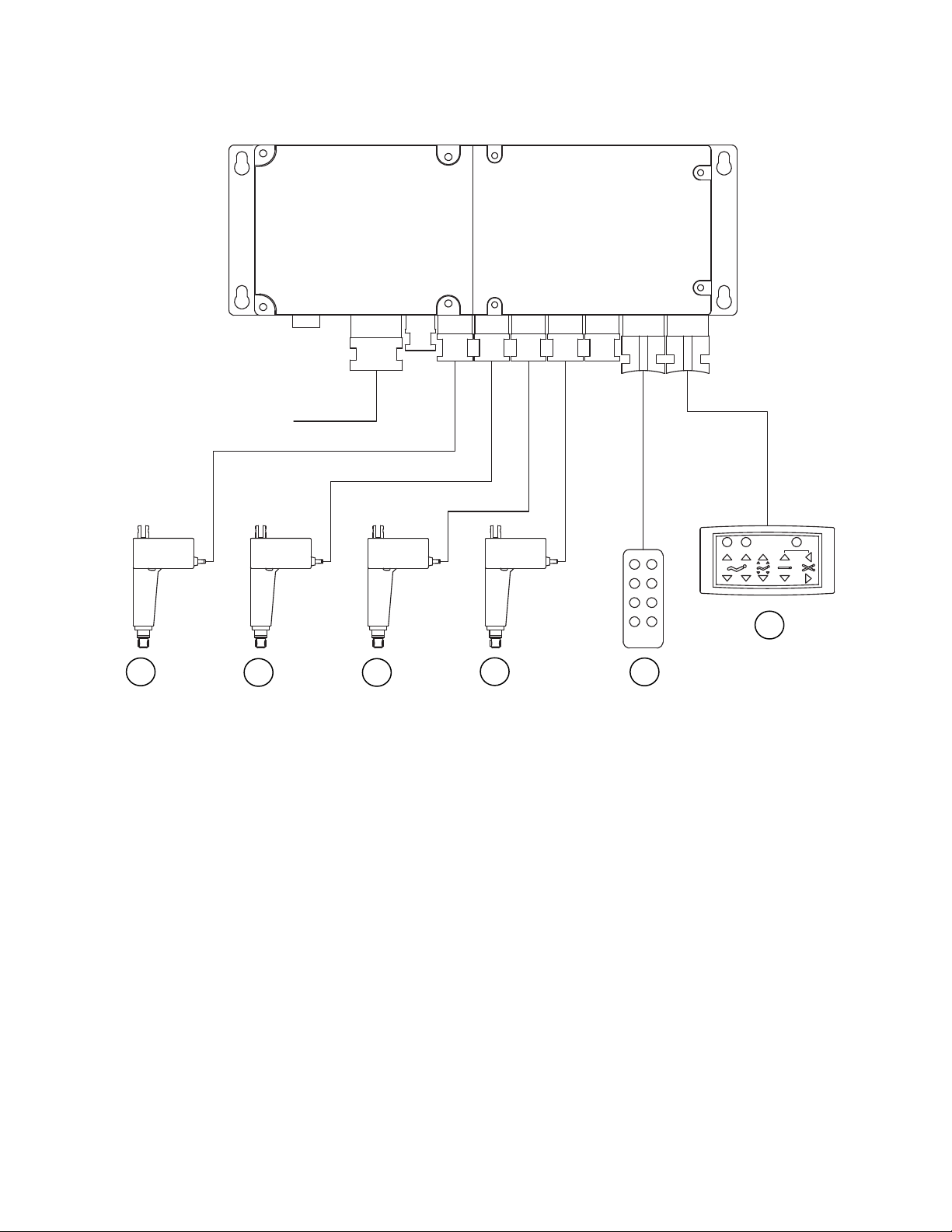
Control Box Socket Identification
1
Power Cord
3
24
F
1
Head
Deck
2
Knee/Foot
Deck
3
Hi/Lo
Head
4
Hi/Lo
Foot
P
Pendant
Footboard
Control
Steps for Isolating Electrical Problems
1. Check all connections.
2. Exchange pendant with a known working pendant.
3. Exchange actuator plugs at known working control box ports.
4. Check actuator with a known working control box.
IF USE OF THIS TROUBLESHOOTING GUIDE DOES NOT CORRECT THE PROBLEM PLEASE CALL
CUSTOMER SUPPORT AT 1 (636) 239-7600.
Manual Number 1100072_5 Save these instructions Page 11 of 14
Page 12
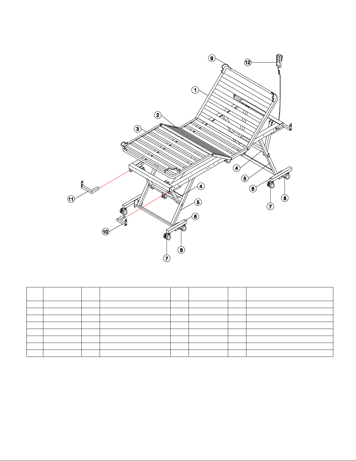
Bed Diagram
Parts List
Item
No
1 5170010BEI 1 Head Deck 9 3040025 4 Mattress Retainer
2 5170011BEI 1 Knee Deck 10 5340009BEI 2 Right Hd/Left Ft Board Bracket
3 5170012BEI 1 Foot Deck 11 5340010BEI 2 Left Hd/Right Ft Board Bracket
4 5170003BEI 2 Elevation Arm 12 4040117 1 Pendant
5 5170004BEI 2 Elevation Leg N.S. 4040113 2 Actuator – Elevation
6 5240074BEI 2 Caster Base N.S. 4040114 1 Actuator – Head
7 4040122 4 Caster - Locking N.S. 4040115 1 Actuator – Foot
8 4040121 4 Caster - Non-Locking N.S. 4040116 1 Control Box
Note: N.S. – Not Shown
Part
Number QTY DESCRIPTION
Item
No
Part
Number QTY DESCRIPTION
ATTENTION: Only use authentic NOA Medical Industries, Inc. replacement parts.
Manual Number 1100072_5 Save these instructions Page 12 of 14
Page 13

MAINTENANCE AND CLEANING
Maintenance and cleaning procedures should be performed at least once a year or as required.
Cleaning and Disinfecting The Bed
1. Unplug power cord before cleaning or performing maintenan ce on electric bed.
2. Do not submerge the pendant in liquid.
3. Do not steam or pressure wash the bed or any of its components.
4. Wipe down actuators, control box, and pendant with a damp, well wrung out cloth or with a disinfecting wipe.
5. Excess water or liquid may damage electrical parts and poses a shock hazard.
6. Wipe down the remainder of the bed with a disinfectant.
7. Allow the bed to dry completely before using.
Periodic Inspection
1. Perform the procedure “STEPS TO PREVENT BED FIRES” listed in this manual.
2. Review “REDUCING THE RISK OF ENTRAPMENT” listed in this manual.
3. Review and inspect for compliance to the “WARNINGS” listed in this manual.
4. Check casters to ensure they lock, if applicable, and roll properly.
5. Inspect all bed components for damage or excessive wear.
6. Visually examine all welds for cracks.
7. Inspect the deck components for bending or damage.
8. Check the motor actuator shaft and its connections for bending, damage, or excessive wear.
9. Check actuator ends and its mounting hardware for bending or excessive wear.
10. Inspect all bolts and fasteners. (Do not over tighten bolts at pivot points.)
11. Check all cords for cuts or other damage.
12. Make sure all plugs are fully seated.
13. Make sure all cords are free of moving parts.
Manual Number 1100072_5 Save these instructions Page 13 of 14
Page 14

LIMITED WARRANTY
The Manufacturer warrants to the original us er (Customer) all products manufactured by the
Manufacturer to be free from defects in material and workmanship under normal use and service
for a period as specified below. If such a defect appears and Customer has given immediate
written notification of same, the Manufacturer shall replace or repair such part at the
Manufacturers option. The Manufacturer will require the return of the defective part to establish
the claim. The Manufacturer’s obligation under this warranty shall be limited to said replacement
and/or repair. Installation and freight costs for replaced or repaired items remain the responsibility
of the Customer. This warranty does not cover f ailure due to negligence, acciden t, deliberate
abuse, nor improper installation and/or maintenance. Modifications made to products (including
modifications without the expressed written consent of the Manufacturer) shall void this warranty
in its entirety. NO FURTHER WARRANTIES, EXPRESSED OR IMPLIED, INCLUDING, BUT NOT LIMITED TO,
WARRANTIES OF MERCHANTABILITY OR FITNESS FOR A PARTICULAR PURPOSE NOT SPECIFIED HEREIN,
ARE MADE BY THE MANUFACTURER, AND THIS WARRANTY SETS FORTH THE FULL EXTENT OF THE
LIABILITY ARISING FROM THE MANUFACTURE, USE OR SALE OF THE PRODUCTS AND MATERIALS SOLD
HEREUNDER. No allowances will be made for delays or loss of profit, nor for any other special,
indirect or consequential damages or injuries, whether based on tort or contract.
Applicable warranty periods commencing from date of shipment from NOA are as follows:
Welds ……………………………………………………….......................... Lifetime
Electrical components
Mechanical components
Head and Foot Boards…
………………………………………………………… 3
……………………………………………………… 3
………………………………….............................. 1
years
years
year
Manual Number 1100072_5 Save these instructions Page 14 of 14
 Loading...