

Page 1

Page 2

2 11
Owner’s Manual
NMC3 / NMB3
This manual will explain how to install your unit as a whole. Detailed
instructions for each; NA2 amplifier, NR controller and N3C/N3B
speakers can be found separately inside your NMC3 / NMB3 package.
*We strongly recommend to take the time and read each of the manuals*
Thank you for purchasing a NOAM Marine audio system. Your stereo system has been
designed and manufactured to exacting standards in order to ensure years of musical
enjoyment. At NOAM we plan and design our products so you can install it by yourself
and save the extra dollars for a professional installation. But, for maximum performance,
we highly recommend that you have your new NMC3 / NMB3 installed by a professional
audio shop. Professional audio dealer has the training, expertise and installation equipment
to ensure optimum performance from this product. Should you decide to install the system
yourself, please take the time to read all manuals thoroughly to familiarize yourself with its
ins
tallation requirements and setup procedures. If you have any questions regarding the
instructions written in any of the manuals or any aspect of your system’s operation,
please contact your authorized NOAM dealer for assistance or directly to us at
What’s Included
Introduction
NA2 Amplifier:
NR Controller:
NMC3 NMB3
N3C - Pair of Chrome 3.5” waterproof
speakers
NR – Waterproof Bluetooth Controller
NA2 – 2 channels Marine Amplifier
All wires and mounting accessories
NR – Waterproof Bluetooth Controller
NA2 – 2 channels Marine Amplifier
All wires and mounting accessories
N3B - Pair of Black Aluminum 3.5”
waterproof speakers
* Detailed accessory list for each speakers, controller and amplifier can be found inside each
component’s manual.
Both NMC3 & NMB3 were built as a system. All included components of the unit; Speakers,
amplifier & controller were designed and tuned to match one another and function as a full
audio system.
The NA2 is an IPX6 waterproof, state of the art, Class D, 2-channel full range amplifier,
well-tuned to power the N3 speaker right to its best performance.
The NR Bluetooth controller is your head unit. The NR features Bluetooth® streaming and
AUX input. Rated at IPX7 waterproof level, your NR will endure wild weather conditions for
years.
®
Page 3
10 3
N3 Speakers:
The pair of N3 speakers features 3.5” Water-Proof Full Range Speaker, cased in a
high-quality Aluminum housing.
Your N3 speakers will fit any Motorcycle / ATV handlebar at 7/8”, 1” & 1.25” diameter.
* THIS MANUAL AND OTHERS CAN ALSO BE
FOUND ON OUR WEBSITE UNDER ‘SUPPORT’
SECTION *
WWW.NOAMAUDIO.COM
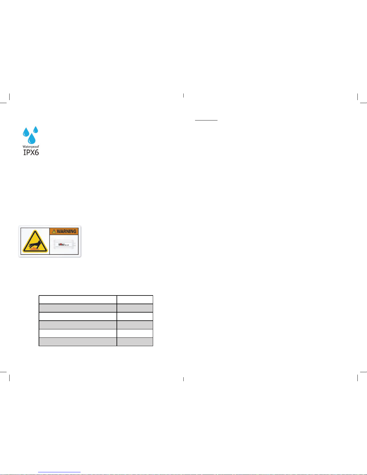
Waterproof:
Your NA2 amplifier is an IPX6 waterproof level.
Though this is a Marine IPX6 rated amplifier,
whenever possible, mount the amplifier in a
dry, well-ventilated location that does not interfere with
other factory installed electronic devices. If a dry
environment is not available, a location that is not exposed
to heavy splashing may be used.
While this amplifier is designed to be water-resistant, it
should never be submerged under water or subjected to
high-pressure water spray. Do not install where it will be
directly exposed to the elements.
Heaving an amplifier sealed to the
elements at IPX6 level means that
heat generated inside the amp has
nowhere to escape. Playing hard
with your NA2 will get it Hot. That’s
fine and normal. But, avoid touching the amplifier’s surface
during or right after use.
Specifications:
MAX POWER AT 4 Ω
WATERPROOF LEVEL
TOTAL HARMONIC DISTORTION
S/N RATIO REF 1W AT 4 Ω
FREQUENCY RANGE
FUSE RATING
150W
IPX66
0.07%
>90dB
20Hz-20KHz
20A
Page 4
4 9
A. Installation Applications:
The NMC3 / NMB3 is designed for operation with 12 volts, negative-ground electrical
systems. Using this product in systems with positive ground and/or voltages other than
12V may result in damage to the product and will void the warranty.
B. Safety Considerations:
• Though this is a Marine IPX6 rated amplifier, whenever possible, mount the amplifier in a
dry, well-ventilated location that does not interfere with other factory installed electronic
devices. If a dry environment is not available, a location that is not exposed to heavy
splashing may be used.
• While this amplifier is designed to be water-resistant, it should never be submerged
under water or subjected to high-pressure water spray. Do not install where it will be
directly exposed to the elements.
• Securely mount the amplifier so that it does not come loose in the event of a
collision/sudden jolt or as a result of repeated vibrations during normal operation.
• Check before drilling to make sure that you will not be drilling into an exterior panel/hull,
fuel tank, gas/brake line, wiring harness, or other vital system.
Heaving an amplifier sealed to the elements at IPX6 level means
that heat generated inside the amp has nowhere to escape. Playing
hard with your NA2 will get it Hot. That’s fine and normal. But, avoid
touching the amplifier’s surface during or right after use.
Do not mount the amplifier in the engine compartment or in any areas of extreme
heat. Mounting the unit in the engine compartment will void your warranty.
• Protect all system wires from sharp edges (metal, fiberglass, etc.) by carefully routing
them, tying them down and using grommets and loom where appropriate.
• Secure all wiring as needed, using cable ties or wire clamps to protect them from
moving parts and sharp edges.
Do not run system wiring outside or underneath the vehicle/vessel. This is an
extremely dangerous practice, which can result in severe damage/injury.
More about the NA2 Amplifier
Get to know your NA2
The NA2 amplifier is state of the art Class D amplifier designed to
provide great amplification in a small space for your motorcycle / ATV
audio system. The NA2 is a 2-channel full range amplifier.
The NA2 amplifier is meant to work with the NOAM NR Bluetooth
controller. The NR controller is your audio source head-unit, able to
trigger your amplifier ON/OFF.
®
What’s Included
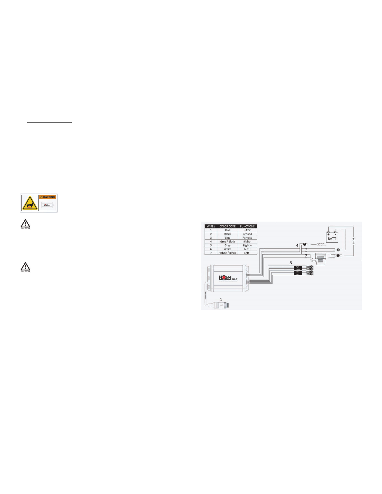
• NA2 - 2 channels Marine amplifier
1. Input – waterproof DIN plug allows you to connect your NA2
amplifier to the NOAM NR Bluetooth controller/receiver.
2. Red / positive power wire – includes a 20A fuse and fuse holder.
3. Black / ground power wire.
4. Blue / remote Turn On - *optional – you don’t need to use it in order
to power your NA2 amplifier
5. Output channels
• 6’ power wire
• 20A fuse and fuse holder
• 4 pcs of mounting screws
®
Page 5
8 5
Refer to section C
TROUBLESHOOTING
Problem Cause Solution
It just doesn’t
sound right
It just doesn’t
sound right
Speaker are connected to
the wrong output
Refer to section C.5 of
this owner manual
Amplifier
doesn’t turn on
Balance
Reversed
Output
Distorted
Output shuts
o after a while
Blowing Fuses
Controller wasn’t
turned ON
Did you remember to press
and hold the controller’s power
button for 3-5 seconds?
Faulty fuse
Remove fuse and check
with continuity meter.
Replace if necessary.
Poor connection integrity
Check “+12V” and “Ground”
leads for pinched wires; ensure
tight connections.
Poor connection integrity
Correct Speaker
Wire Orientation
NR/Audio player
Volume Set Too High
Lower NR/Audio
player Volume
Overheating condition
(Thermal Protection)
Excessive Output Levels
Lower the Volume
Contact us at
[email protected]
Amp is defective
The amplifier is picking
up alternator or
radiated noise
Move the audio cables away
from the power wires
Check the alternator and/or
voltage regulator. Test for
weak battery or add water
to the battery
Make sure amplifier mounting
area has adequate space for
ventilation and heat
dissipation.
Whining or
ticking noise
while the
engine is ON
Page 6
6 7
C. Installation Procedure/Connections
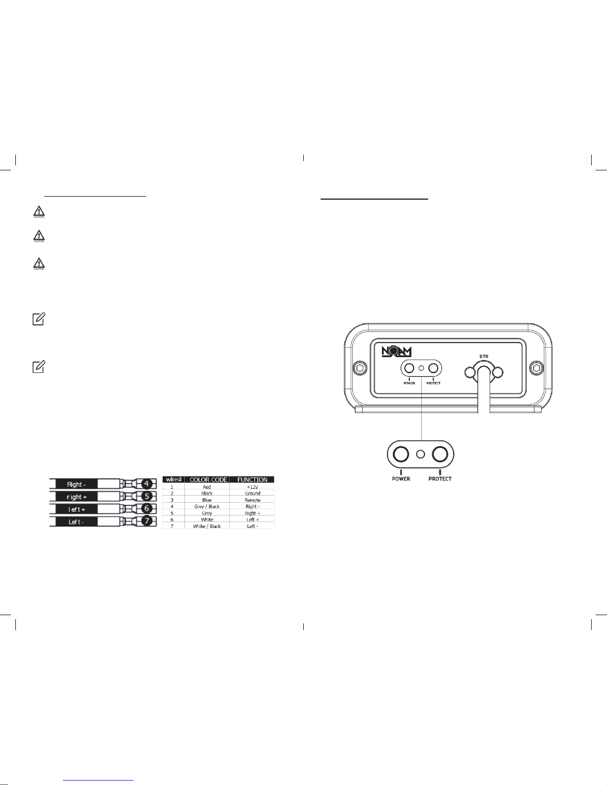
Power/Protect Indicator:
If you feel unsure about installing this system yourself, have it installed by a
qualified technician.
Before installation Disconnect the NEGATIVE battery post connection and secure
the disconnected cable to prevent accidental reconnection during installation. This
is an essential safety precaution during installation!
Avoid running power wires near the low-level input cables, antenna, power leads,
sensitive equipment or harnesses. The power wires carry substantial current and
could induce noise into the audio system.
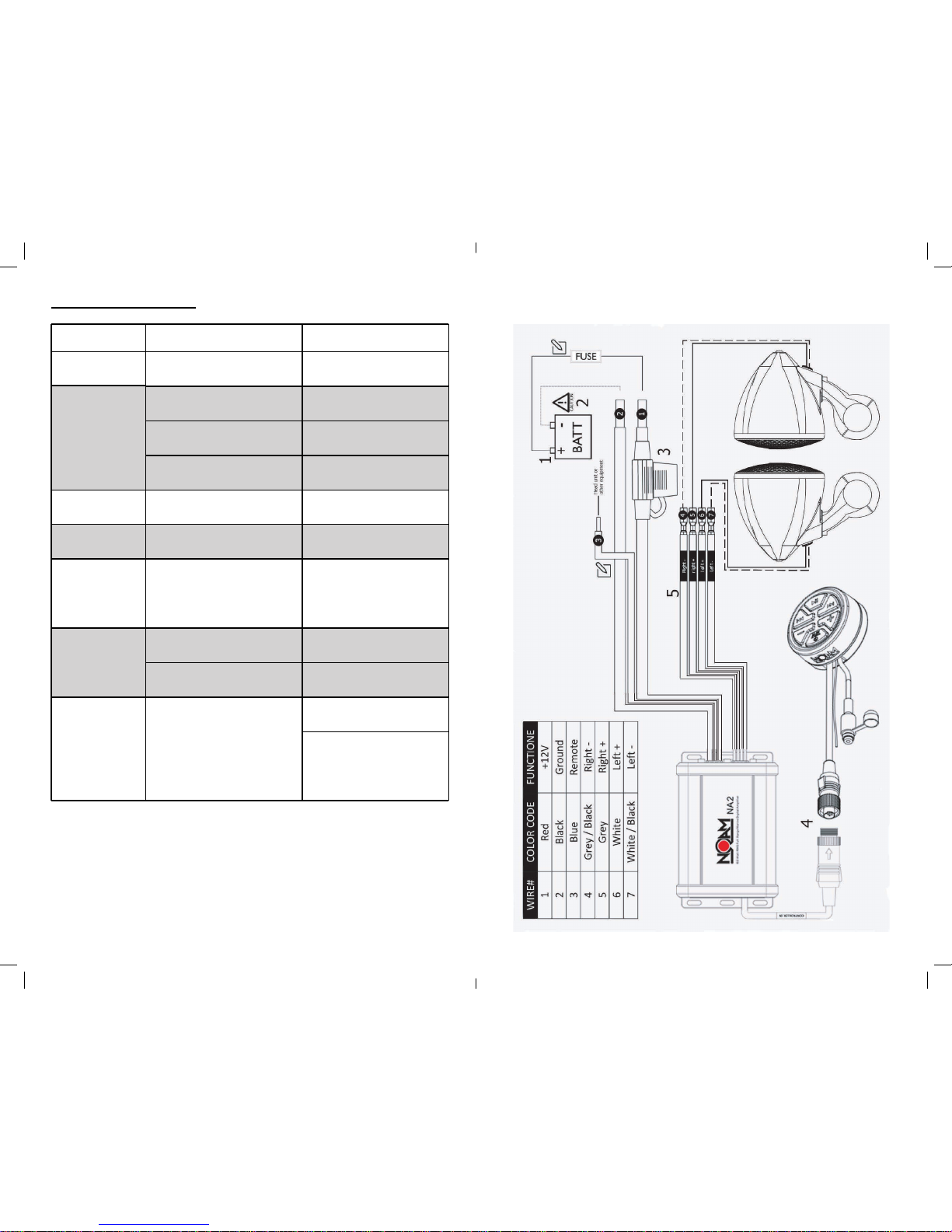
1. Connect the RED power lead to the positive (+12V) battery post.
There are two status indicator lights on the end panel of the amplifier.
1. “POWER” (Blue): Lights to indicate that the amplifier is turned on
and operating normally. 2. “PROTECT” (Red): Lights to indicate the
amplifier’s protection circuitry has been activated to prevent product
failure due to thermal overload, over current or short-circuit to the
amplifier’s outputs. When this protection mode is activated, the
amplifier will shut down to protect its circuitry. When the problem is
corrected, the amplifier will return to normal operation and the
“Protect” LED will shut o.
3. Fuse. Your NA2 already includes a 20A fuse. The NA2 power wires are 8’ long, while the
Fuse housing located on the Red/Positive power wire at 3.3’ of wire from the amplifier.
4. Connect the NR male controller DIN plug to the NA2’s female DIN plug.
* Powering the NA2 amplifier. Long pressing your NR controller’s power button for few
seconds will trigger both the NR controller and the NA2 amplifier ON/OFF.
5. Run the speakers wires to the amplifier’s output.
Make sure about correct polarity when connecting your speakers to the amplifier.
speaker’s Red wire (+) should connect to color (+) output channels.
speakers’s Black wire (-) should be connected to color / Black (-) output channels.
Spea
ker connection color codes:
6. If you haven t already done so, mount the amp now.
7. Now you should be good to go and play tunes for the first time.
2. We strongly recommend to run the Black/Ground power cable to the negative (-12V)
battery post.
Blue / Remote Turn-On wire is not required for installing or running your NA2
amplifier. The NR controller is able to power trigger your amplifier
You have plenty of power wire length before the fuse holder (3.3’). Strive to leave
no more than 18” (45.7 cm) of wire between the fuse holder and the battery
positive (+12V) terminal. You can cut the remaining wire.
Page 7
Page 8
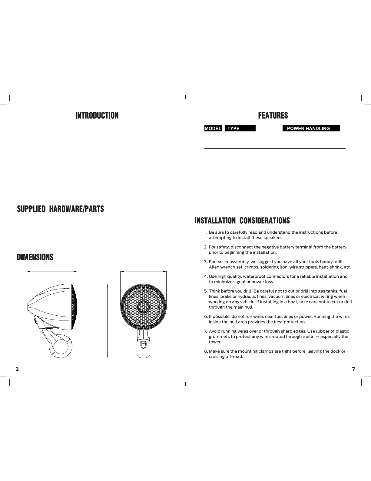
107.6mm(4.24”)
158.8mm(6.25”)
98.8mm(3.89”)
Thank you for choosing NOAM N3 speakers.
We invested a lot of thought, time and eort into
the creation of these speakers. all while great sound
and ease of use are on our mind to lead the way.
Your N3 speakers went through Three rounds
Of QC before being packed.
If and at any given time, you have any questions
Or concerns, please feel free to contact us at:
[email protected]
Enjoy Your Ride!
. 1 pair - N3 speakers
. 1 pair - 16mm - M8 Allen head screw
. 2 pair - 14mm - M5 Allen head screw
. 2 pair - of each 7/8 & 1” rubber inserts
Mounting Dimensions(enclosure):
Power Rating: 100 W MAX / 50 W RMS
Sensitivity: 90 dB @ 1W/1M
MidBass: 3.5” Water-Proof Full-
Range Speaker
Nominal Impedance: 4 ohm
Length: 107.6mm(4.24”)
Width: 98.8mm(3.89”)
Height: 158.8mm(6.25”)
N3B 3.5” Motorcycle Speaker 100W/50W Power Handling
N3C 3.5” Motorcycle Speaker 100W/50W Power Handling
Page 9
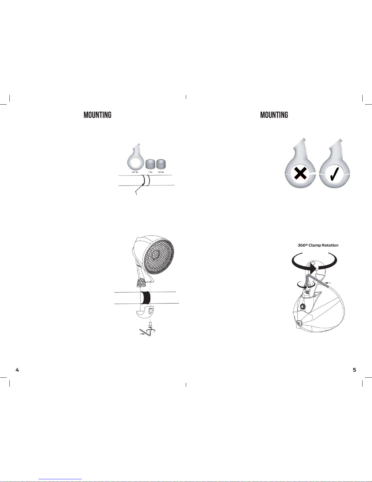
Step 1: Choose the correct rubber insert’s
size for your handlebar and place it around
the handlebar.
note: 1.25” handlebar doesn’t require
any rubber inserts for installation.
Step 2: place the speaker’s bracket
over the rubber insert/handlebar.
Using a M4 Allen wrench, screw the
two M5 screws.
Best practice: Make sure you
screw each side’s M5 screw
evenly.
Speaker Rotation: Using
a M6 Allen wrench, loosen the
M8 screw and adjust the right angle of
your speaker.
Best practice: direct the speaker
towards your helmet.
rubber insert
M6 Allen
wrench
M4 Allen
wrench
Page 10
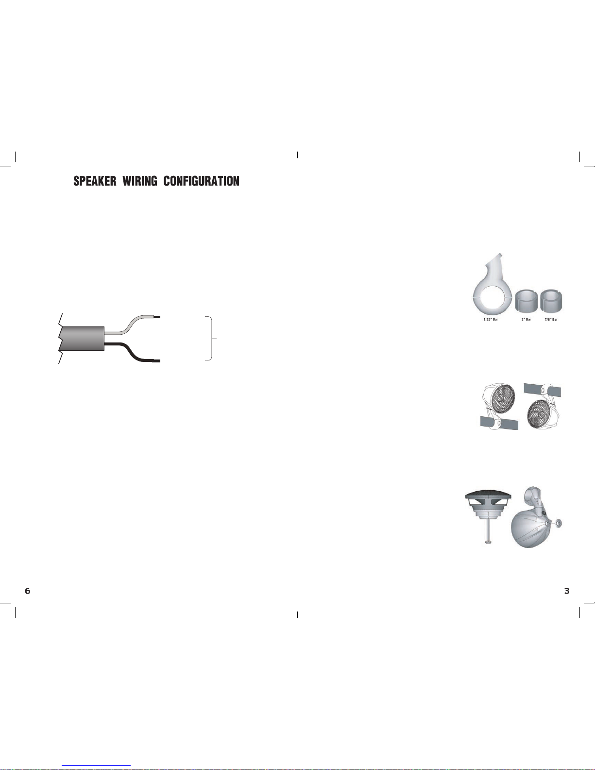
Black SPKR (–)
Red SPKR (+)
Speaker
Wiring
Speaker Wiring:
The N3 has long wiring, well protected in a wiring sleeve.
- You can cut the wiring to a desired length for a clean installation.
But, make sure to do so only after you finished installing your entire
audio system, including its amplifier.
- Connect the speaker wires to your amplifier ensuring correct polarity;
Red to positive and Black to negative.
Running your N3 wiring:
Run the N3’s wires along and attached the Bike’s cage/body
all the way to the amplifier’s location.
Use cable ties to ensure it will be kept away from sharp edges to avoid
the possibility of getting pinched by moving mechanisms.
...to ensure it is away...
Importnt featurs of the N3
Please read before first use
Handlebar Fitment:
Your N3 speakers can be mounted
on 7/8”, 1” & 1.25” handlebars.
Inside the N3 package are two
rubber inserts:
For 7/8” handlebar, use the
thicker rubber insert.
For 1” handlebar, use the
thinner rubber insert.
For 1.25” handlebar, no rubber
insert is required. simply mount the
bracket directly on your handlebar.
Choosing the right angle:
The N3 speakers can be mounted
in various angles.
The M8 screw found on the bottom of
the speaker can be loosened to allow
full rotation of the speaker. (see page 5)
The bracket itself can also be
rotated around the handlebar, allowing
you to mount the speaker above or
underneath the handlebar.
Replacing the speaker:
If, for any reason, you need to replace
your speaker, you can easily do it.
on the back of your N3 speaker you
will find a M6 Allen screw. using a M4
Allen wrench, unscrew this screw.
You can now take o your speaker and
replace it with new one.
For spare parts, contact us at:
[email protected]
Page 11
www.noamaudio.com
Visit us at www.noamaudio.com
and sign up to our newsleer to
stay tuned. we are always working
new excing products just for you!
Bluetooth Receiver
Page 12
2
Introducon
7
Installaon
Thank you for choosing NOAM NR
Bluetooth remote controller. We invested
a lot of me and effort planning and
designing the perfect cotroller for your
audio system.
The NR controller went through three
rounds of QC before being packed.
If at any given me you have any
quesons or concerns, please feel free
to contact us at: [email protected]
Enjoy your ride!
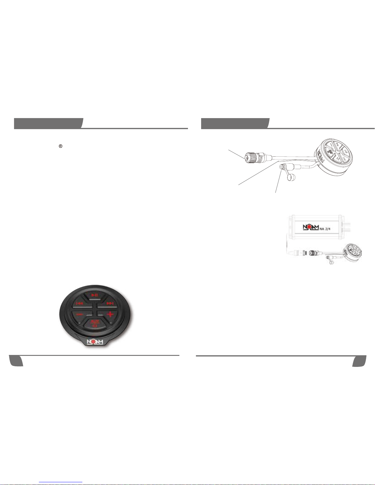
NR wires and plugs diagram
Amplifier-Controller DIN plug
Amplifier-Controller DIN plug
Remote In - Blue Wire
The remote-in is an extra feature we added to the NR. Connecting the
remote-in wire to a remote-out wire of another device will allow this
device to trigger your NR ON/OFF.
*note. It’s an optional feature only. You don’t need to use this wire in
order to run your NR.
The NR controller has a DIN
plug. This plug can be connected
directly to the NOAM NA2 & NA4
amplifiers.
Remote power triggering:
The NR is able to power the NA
amplifiers. whenever you turn
the NR ON or OFF the NA2/4
amplifier will do the same.
Aux input - optional
If you already had a peripheral music device on your bike such as satellite
radio, MP3 player or GPS, you will take the audio output from that device
and plug it into the female 1/8” mini plug.
* When not in use, please keep the AUX plug sealed by keeping the
protective cap closed.
Remote In
Aux input
Page 13
6
Setup
Pairing bluetooth Deuice
Bluetooth trouble Shoong Guide
AUX Input
Main Key pad Controls
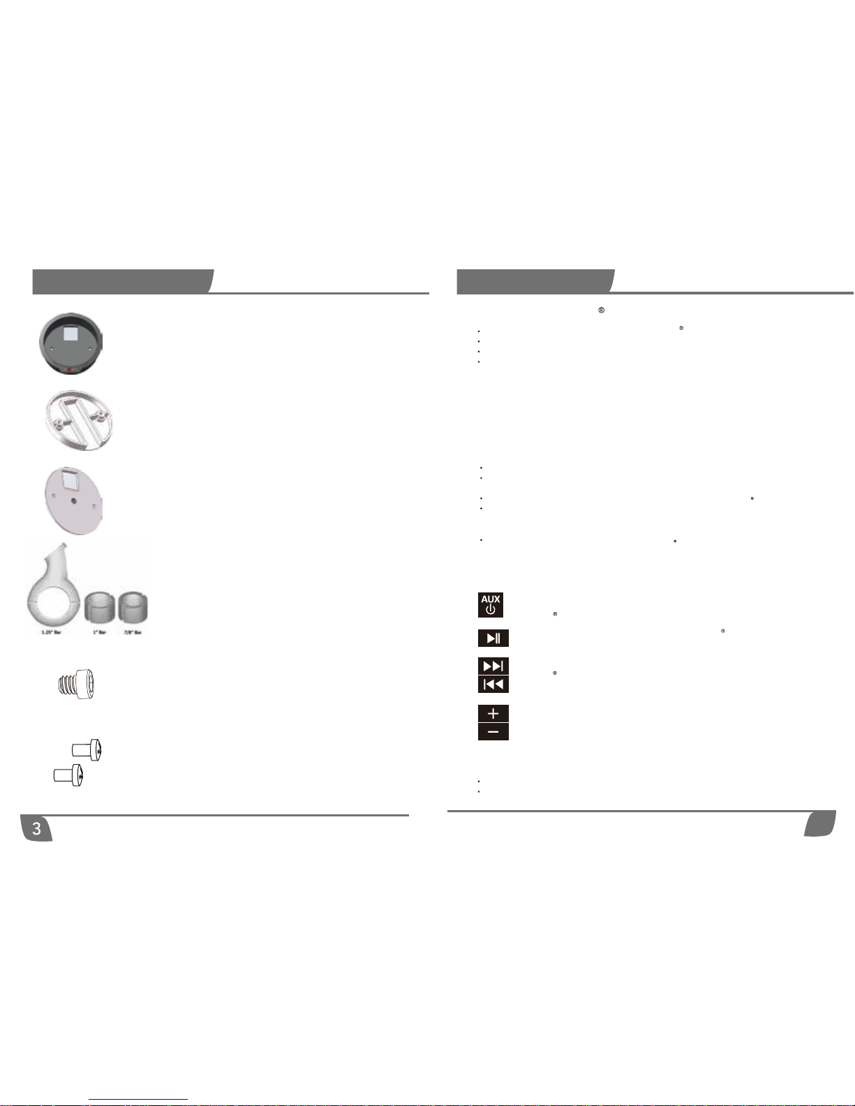
The play pause buon allows you to pause your Bluetooth device from playing. Press
the same buon again and your device will start to play.
The "track up" buon allows you to "skip forward" to the next song saved on your
Bluetooth device. Pressing the "track down" buon once allows you to go back to the
start of the song your’re currently listening to. Press it a second me and go to the start
of the song on your device before the one your’re listening to.
The Volume Up/Volume Down buons will control the volume level of your Tunes, best
pracce: set your audio source’s Volume at around 85% (on your phone, MP3 player
etc) and control the volume using the NR controller
Make sure volume is up on Bluetooth sources
Confirm Pairing if no sound.
Press and hold the AUX/POWER buon for few second to turn the NOAM NR ON. Do
the same to turn it OFF. As menoned above, double tap it to switch between Aux and
Bluetooth modes.
Go to settings on your phone and place Bluetooth setting into ”discoverable”mode.
Search for (NOAM NR)device.
On phone select (NOAM NR) to pair device.
Once a device is paired each time this device is seen by the NOAM NR it will
outomatically reconnect to the device. If no device is present the NOAM NR
outomatically goes into pairing mode and will present itself as discoverable for the
next device present.
Please Note: Once NOAM NR sees power, it will always try and pair as shown
by the flashing POWER BUTTON. If you do not have a paired device with you
while riding, the light will continue to flash.
Connect AUX Input with any media player(MP3 player, Smartphone, Headunit)
Double tap AUX/Power button rapidly to switch between Bluetooth source and AUX
input source.
When NOAM NR is switchod to AUX input source, the Green LED stays on.
Double tap the AUX/POWER button agian and the Green light will shut off, indicating
the unit is now out of AUX mode. The bluetooth device can now once agian be used
and controlled by the key pad.
Note: When the unit is in AUX mode, the buttons on the control panel do not control
anything to do with the peripheral audio device!
Supplied Hardware
Dash or Flush (Rear) mount
plate
Handlebar mount plate
*
not necessary for NUTV5/NUTV5-S models
SS304 Hexagon Socket Head
Screw M6 x 8mm
*
not necessary for NUTV5/NUTV5-S models
2 x SS304 Cross Head Screw
M4 x 8mm
Handlebar mount bracket
and pair of rubber rings
*
not included in the NUTV5 and NUTV5-S
audio systems
Surface mount plate
Page 14
5
Installaon
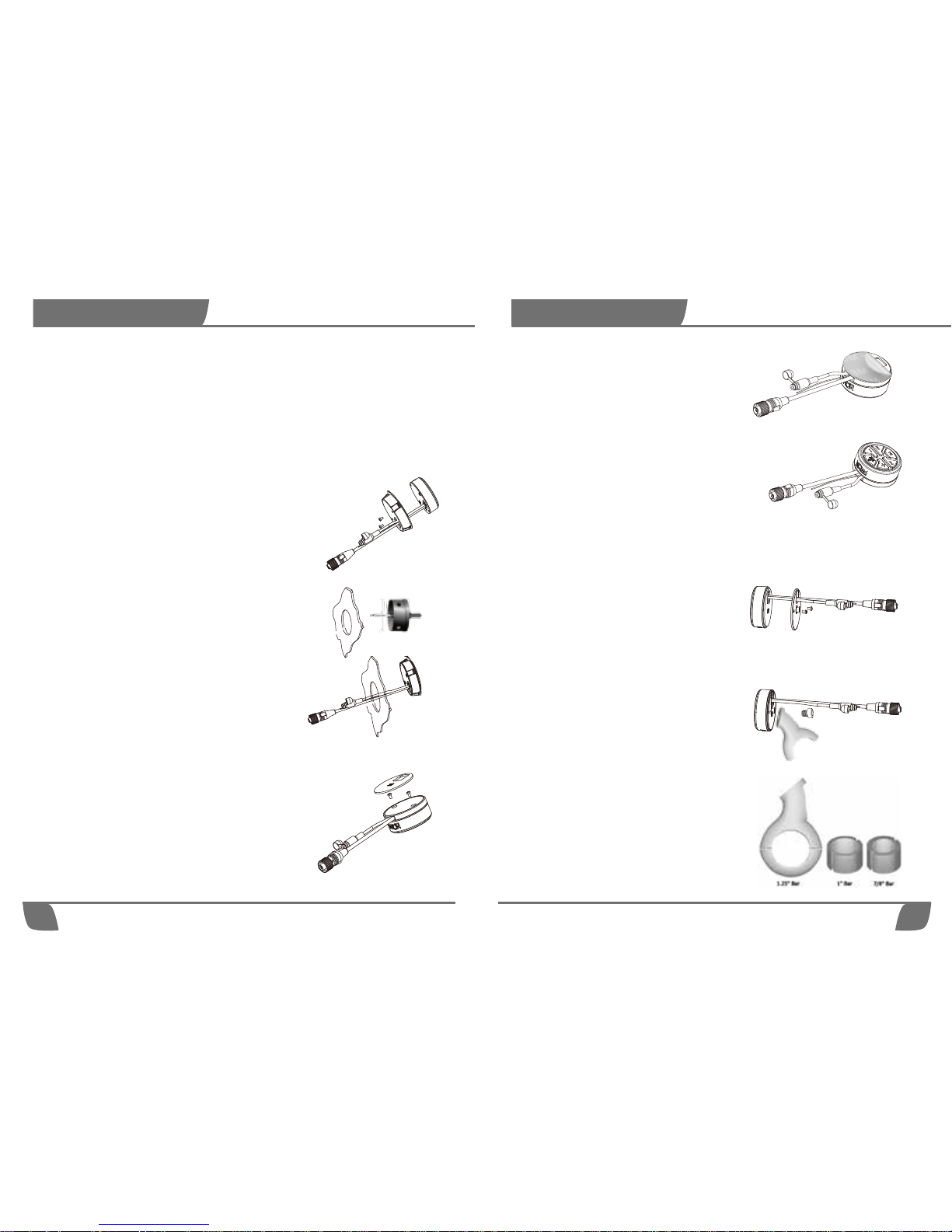
STEP 1: Slide the NR cables through the
Handlebar mount plate and screw the
plate to the back of the NR, using the 2
M4 cross head screw.
STEP 2: Use the M6 Hexagon socket
head screw to screw the handlebar
bracket to the back of the NR.
For a 7/8'' bar - use the Thick rubber ring
For a 1'' bar - use the Thin rubber ring
For a 1.25'' bar - place the bracket
directly on the bar (no rubber inserts
required).
Handlebar mount: This method
will allow you to mount your NR on
round 7/8'' , 1'' & 1.25'' handlebar.
STEP 2: Peel off the 3M scker's cover
STEP3: Place the NR on a perfectly flat surface.
4
Installaon
Mounng yor NOAM NR
The NR controller has 3 mounng opons:
1. Dash or Flush (Rear) mount
2. Surface mount
3. Handlebar mount (not available in the NUTV5 and NUTV5-S units)
Dash or Flush (Rear) mount: This method will
allow the controller to sit flush to the mounng surface.
This requires a perfectly flat surface and ideally should
have access to the rear of the mounng plate.
STEP 1: Slide the NR cables through the Flush
mount plate and screw the plate to the back of
the NR, using the 2 M4 cross head screw.
STEP 2: Using a 2.75'' (70mm) hole saw, drill a
hole in your selected locaon. *Ensure you
have at least 1 inch of clearance on the back
side of your selected mounng locaon.
Surface mount: This method will allow you to
mount the NR on any perfectly flat surface. Using this
method will not require any cung or drilling of the
surface.
STEP 1: Place the NR cables in the rail found on the
inner side of the surface mount plate, and screw
the plate to the back of the NR, using the 2 M4
cross head screw. Then sck the 3M Scker on the
back of the surface mount plate.
STEP 3: Slide the NR through the hole.
STEP 3: Mount the bracket on the handlebar
 Loading...