

Page 1

SKD224 replacement board
Assembly Manual
- Document version 0.1.6 –
© Copyright NMJ 2016
All rights reserved
Page 2
SKD224 replacement board
Assembly Manual
Document
Version
0.1.6
Page 2 of 46
Please read this manual carefully before carrying out the
installation!!! Although our products are very robust, incorrect
wiring may destroy the module!
During the operation of the device the specified technical parameters
shall always be met. At the installation the environment shall be fully
taken into consideration. The device must not be exposed to moisture
and direct sunshine.
A soldering tool may be necessary for the installation and/or
mounting of the devices, which requires special care.
During the installation it shall be ensured that the bottom of the
device should not contact with a conductive (e.g. metal) surface!
Page 3

SKD224 replacement board
Assembly Manual
Document
Version
0.1.6
Page 3 of 46
Content
1. Important Information .............................................................. 4
2. Required tools .......................................................................... 4
3. Required materials ................................................................... 4
4. Operation principle .................................................................. 5
5. Board Connections ................................................................... 7
6. Disassembly of the SKD224 .................................................... 9
7. Installing the replacement board ............................................ 13
8. Replacement of the wheels .................................................... 18
9. Decoder settings ..................................................................... 25
10. Programming tips ................................................................... 26
11. Analog operation ................................................................... 28
12. Notes ...................................................................................... 28
13. CV Table ................................................................................ 29
Page 4

SKD224 replacement board
Assembly Manual
Document
Version
0.1.6
Page 4 of 46
1. Important Information
The manual is a guide to assemble the SKD224 replacement
board and gives some decoder setting recommendations and
programming tips. The replacement board is a drop in replacement
for the original board situated inside the SKD locomotives chassis.
The replacement board contains a DCC decoder and a Smart
Power Supply (SPP) and is suitable for DCC operation. The
decoders have installed a dedicated firmware with factory default
parameter values optimized for the SKD224 locomotives. After a
decoder reset, all the decoder parameters are reverted to the factory
default values.
Reference documents: NA
2. Required tools
- tweezer
- screwdriver
- right plier
- cutter
- cutting plier
- soldering station
3. Required materials
- SKD224 replacement board kit containing the replacement axles
- soldering wire
Estimated assembly time: 30-45 minutes
Page 5

SKD224 replacement board
Assembly Manual
Document
Version
0.1.6
Page 5 of 46
4. Operation principle
The SKD224 replacement board contains a smart power pack (SPP)
and is integrating a DCC decoder with BEMF PID motor control and
4 physical (function) outputs. The decoder controls the charging of
the on board 1 Farad capacitor, and ensures switching to the internal
power supply in case of track contact interruption. This guaranties a
trouble free running of the SKD224 even if the contact with the rails
is lost. The SPP is capable to power the locomotive up to 4 seconds
and can run it up to 30-50 centimeters without DCC power
(depending on the speed). This is especially useful for small 2 axle
locomotives like the SKD224, which has only a few current pickup
points, and suffer very often of DCC power interruption.
At start-up, the board will have a current consumption of 250-300
mA for up to 2 minutes, even if the locomotive is stationary. This is
normal, during this time the SPP is charging the internal capacitor.
In case of external power interruption, after the maximum allowed
timeout has been elapsed (this can be changed altering the specific
CV), the locomotive will stop. The operation can be resumed when
the locomotive is powered again over the rails.
Due to the operational principle, the SPP can be used only in DCC. If
the locomotive is used in DC, the SPP will be not activated.
The lights of the SKD224 are wired to the internal SPP circuit, so
even in the case of contact problems while running, during the
switching between external DCC power and internal SPP, the lights
are stable, and no annoying dimming is visible.
Connections for optional front/rear lights and electrical couplers are
available at both ends of the boards.
Page 6

SKD224 replacement board
Assembly Manual
Document
Version
0.1.6
Page 6 of 46
The on board decoder is full of options: is featuring a SUSI
connector for optional sound module connection, contains Zero
Speed and ABC Braking, with penduling (push-pull operation), has
a RailCom transmitter, and is capable of driving different electrical
couplers. Future options can be also integrated with a firmware
upgrade.
Page 7
SKD224 replacement board
Assembly Manual
Document
Version
0.1.6
Page 7 of 46
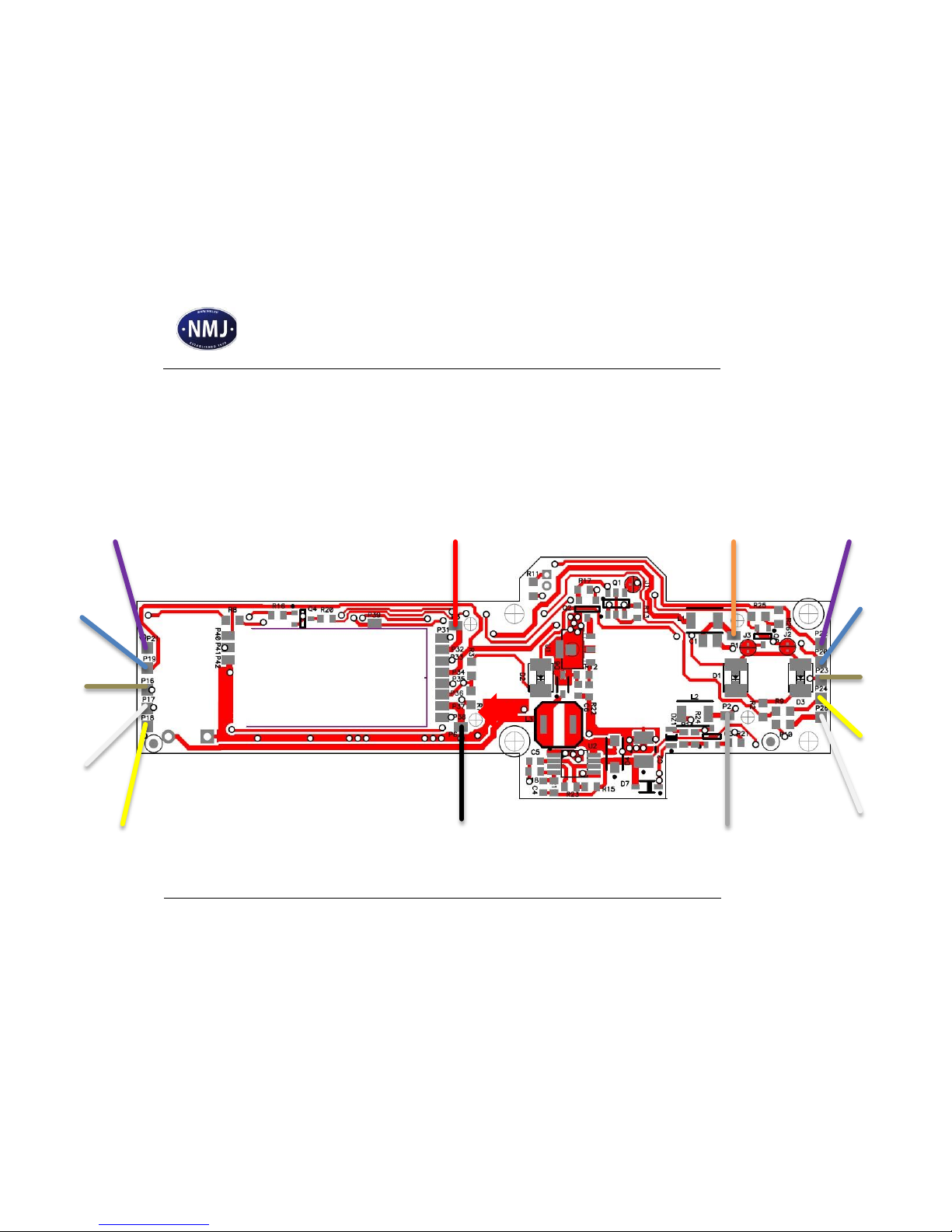
5. Board Connections
(the color coding is made according to NMRA standards, otherwise noted)
Motor Negative Terminal
Motor Positive Terminal
Coupler
Common
Coupler Output
Coupler Output
Coupler
Common
Right Track Connection
Left Track Connection
Lights
Common
(See note 1)
Lights
Common
(See note 1)
Front
White
(See note 2)
Rear
White
(See note 2)
Front
Red
(See note 2)
Rear
Red
(See note 2)
Page 8

SKD224 replacement board
Assembly Manual
Document
Version
0.1.6
Page 8 of 46
Note 1: The positive common terminal for the optional lights
(brown color in the illustration) is not the same as the coupler
positive common (blue in the illustration). It is forbidden to
connect them together.
The front/rear light outputs (white and yellow color) allows
direct connection of LEDs, so no current limiting resistors are
needed. The resistors are integrated to the boards. The Anode
of the LEDs must be connected to the Lights Common, while
the cathode to the front/rear outputs.
Page 9
SKD224 replacement board
Assembly Manual
Document
Version
0.1.6
Page 9 of 46
6. Disassembly of the SKD224
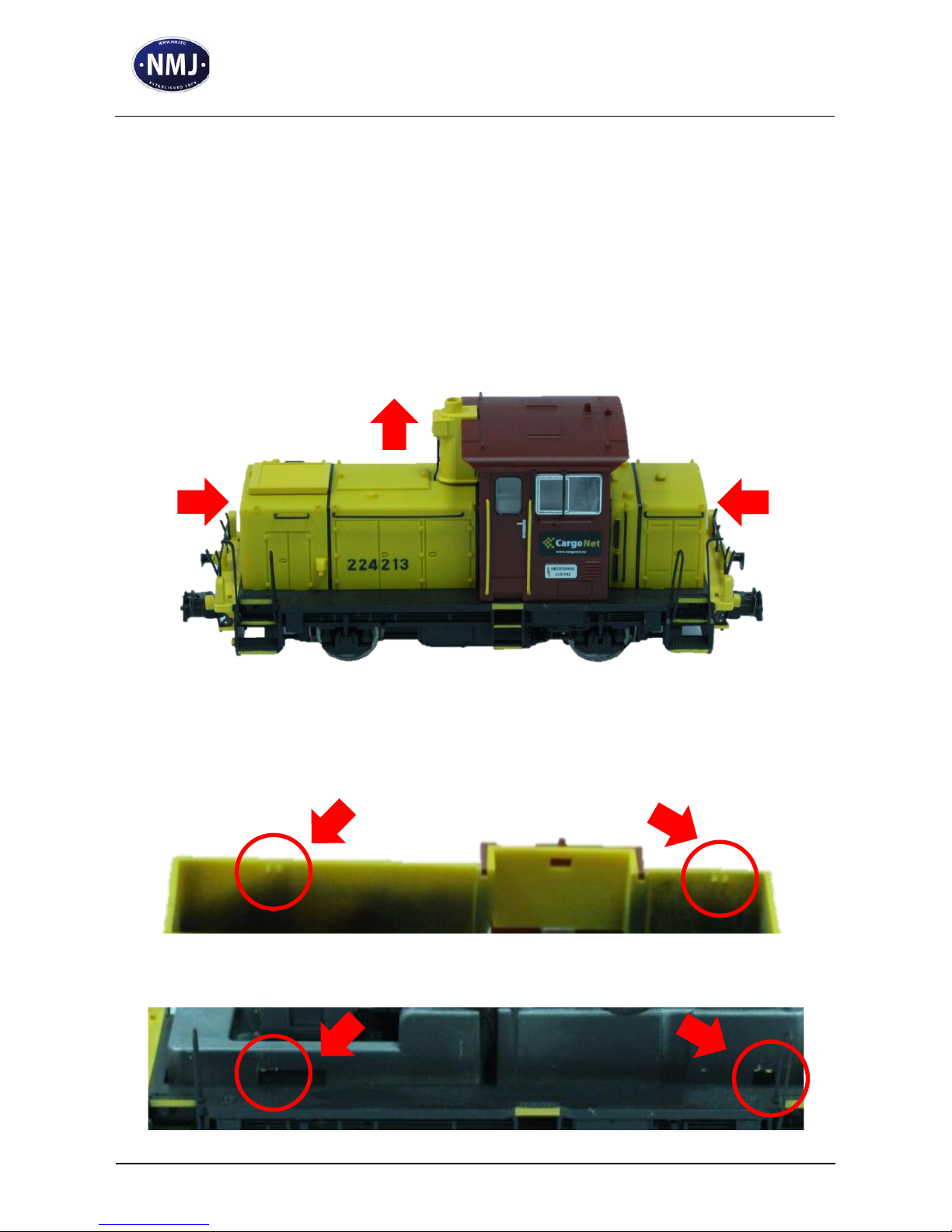
Remove the housing from the chassis. Press in the same time on both
ends of the housing (1), and lift (pull) the housing in the upper
direction (2).
The housing has 4 plastic ears (3), which enters in the 4 recess of the
chassis (4). Using a sharp blade (cutter) can help in the extraction.
1 1 2 3
3
4
4
Page 10
SKD224 replacement board
Assembly Manual
Document
Version
0.1.6
Page 10 of 46
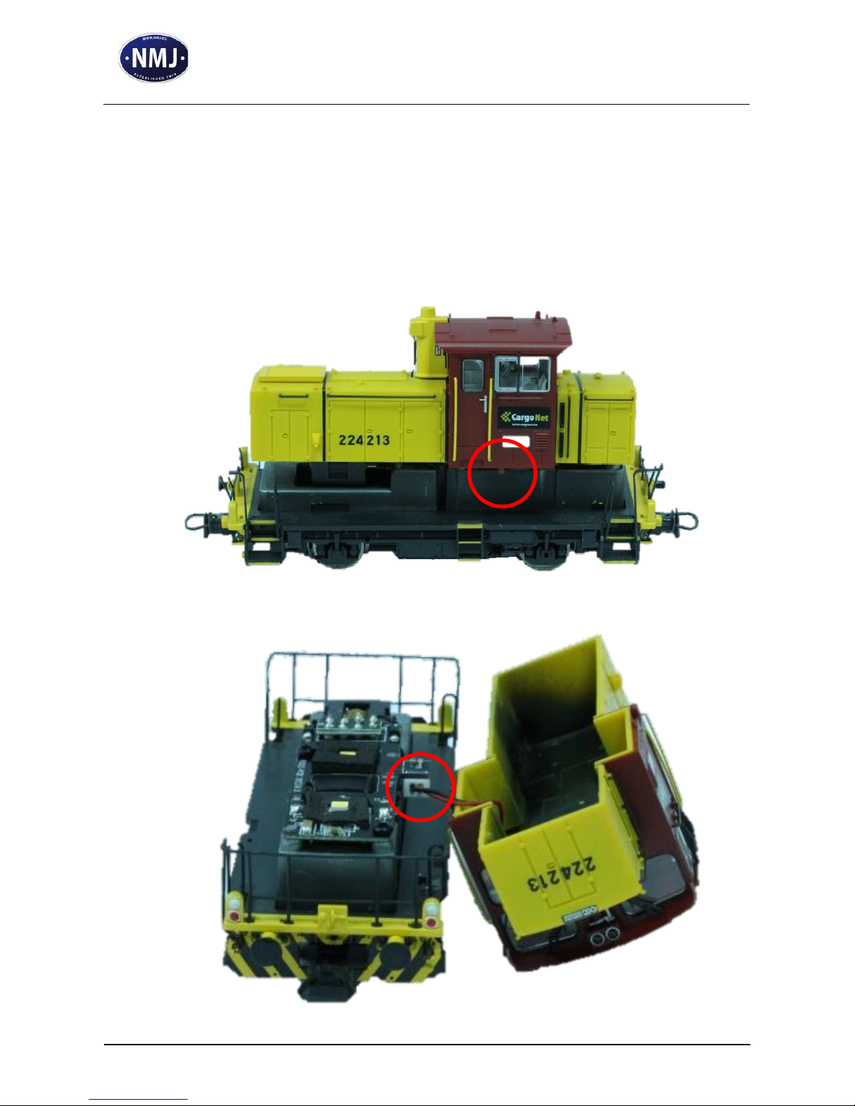
Gently remove the housing, and place it on its side near the chassis.
Do not pull it too far, since the cabin lighting has a cable connection
to the chassis (2). The cabin itself also has 2 plastic pins (1), which
fits in the corresponding openings in the base plate located above the
chassis.
2
1
Page 11
SKD224 replacement board
Assembly Manual
Document
Version
0.1.6
Page 11 of 46
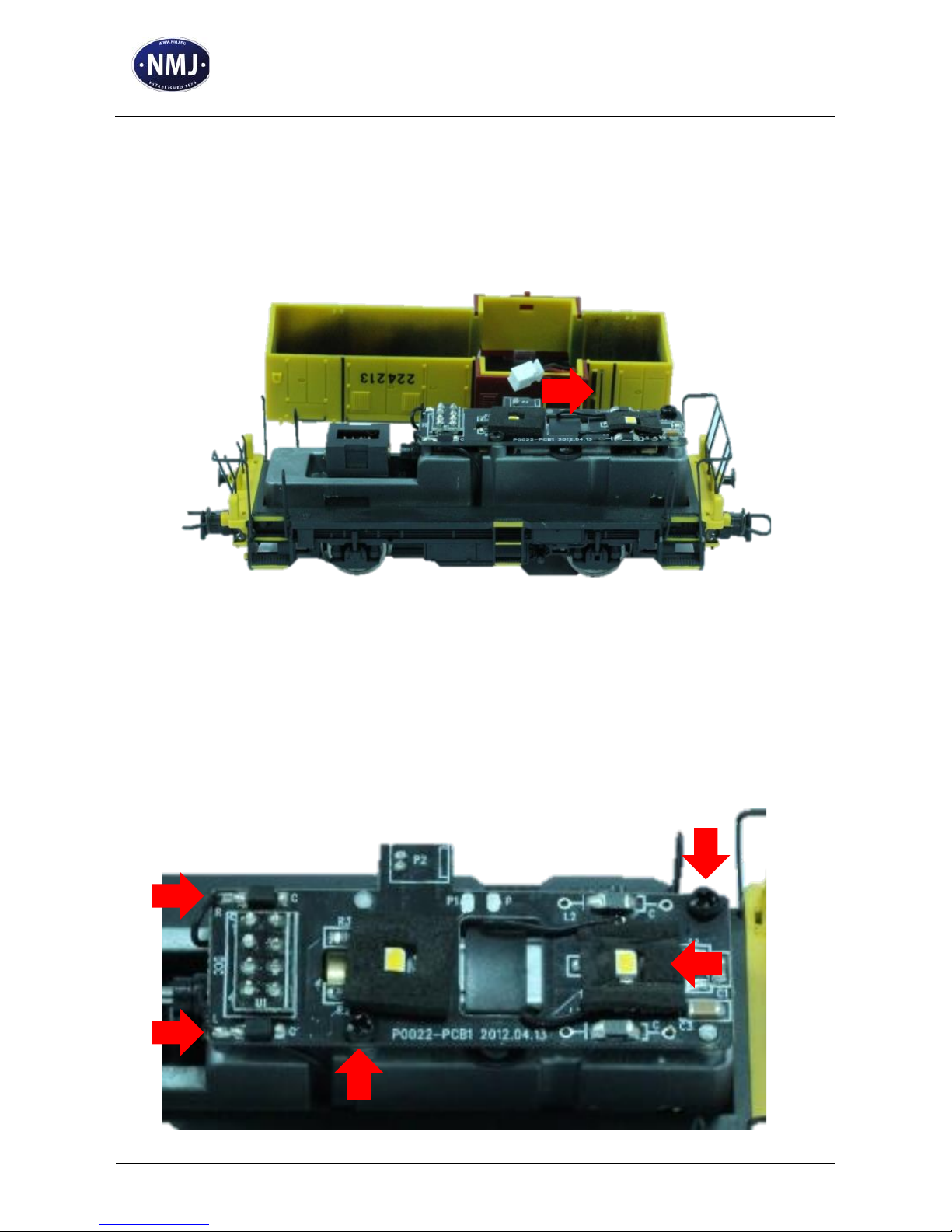
Disconnect the cabin lighting by removing the connector from the
chassis printed circuit board.
Localize the track connections (1), motor connections under the
black adhesive tape (2) and the mounting screws (3) on the chassis of
the locomotive.
1
1 2 3
3
Page 12
SKD224 replacement board
Assembly Manual
Document
Version
0.1.6
Page 12 of 46
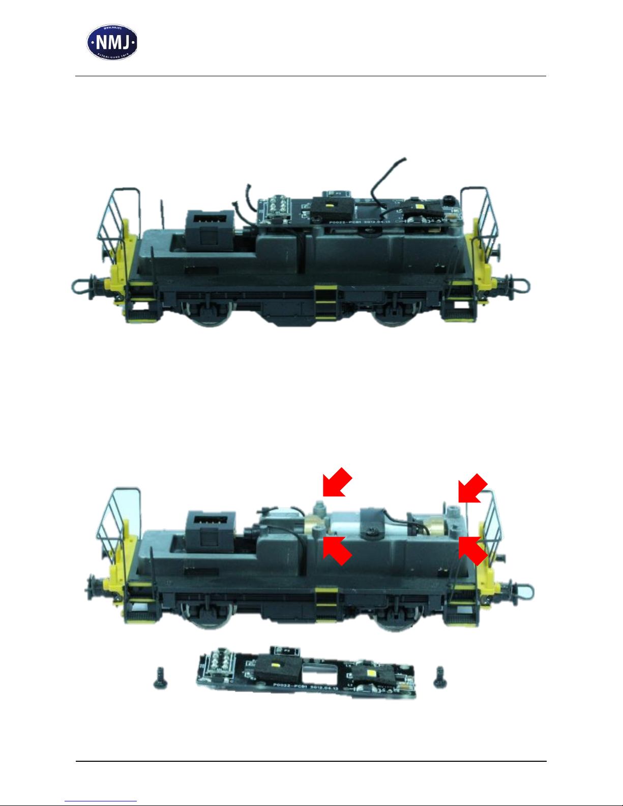
First, unsolder the connection wires (4 in total).
Remove the 2 screws (1), and lift the printed circuit board. Please
note, that there are 2 mechanical centering pins (2) in the chassis,
which will guide the fit of the replacement board.
2 2 1
1
Page 13
SKD224 replacement board
Assembly Manual
Document
Version
0.1.6
Page 13 of 46
7. Installing the replacement board
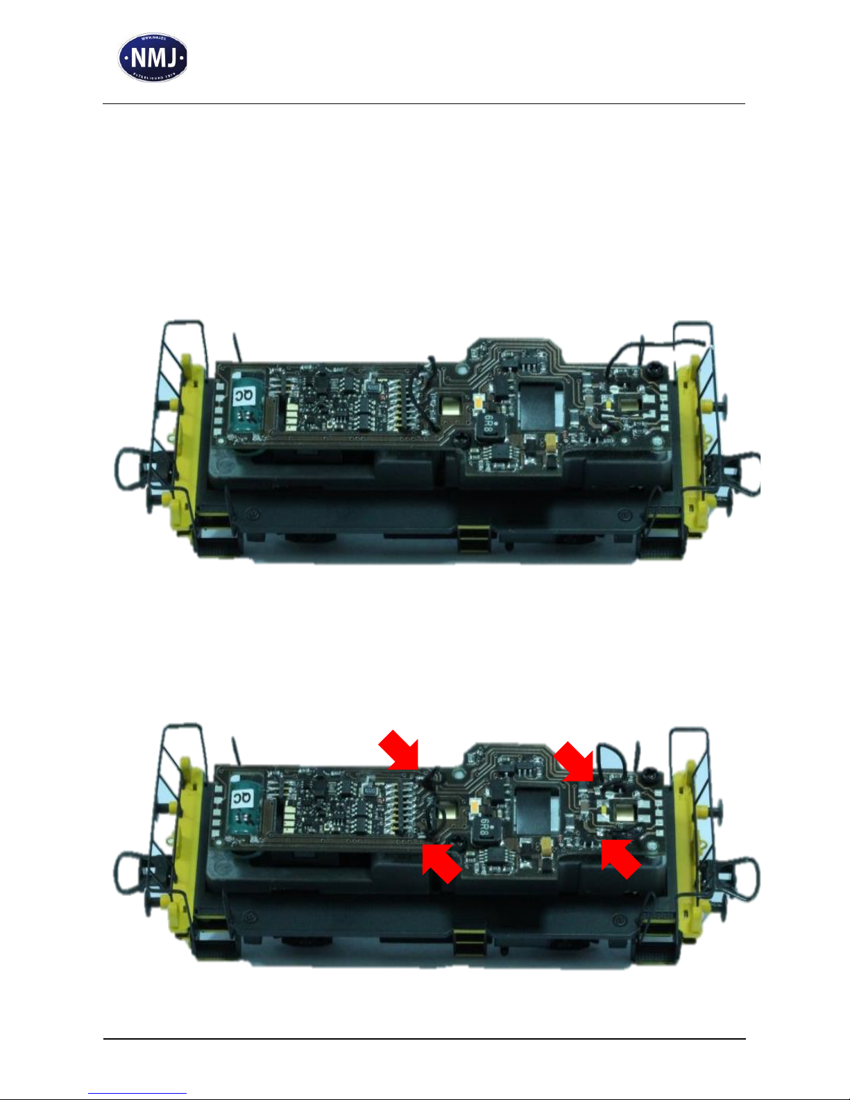
Lead the 4 connection wires thru the corresponding holes in the
replacement board, and fit the board to the chassis using the
mechanical centering pins. Screw the board to the chassis.
Solder the wires to the replacement board.
Page 14
SKD224 replacement board
Assembly Manual
Document
Version
0.1.6
Page 14 of 46
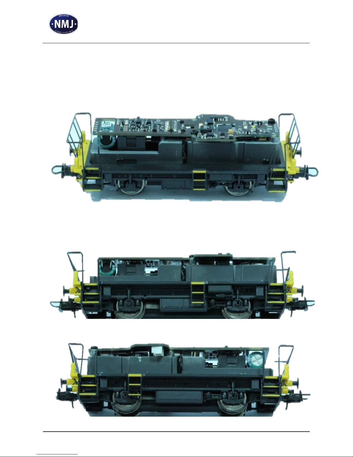
All the wires must be pulled back, and arranged under the printed
circuit board. The motor connection wires must be arranged in such a
way to not touch the flywheel.
The track connection can be arranged on both sides of the chassis in
the available cutouts. If needed, a small drop of cyanoacrylate can be
used to fix the wires to the chassis.
Page 15
SKD224 replacement board
Assembly Manual
Document
Version
0.1.6
Page 15 of 46
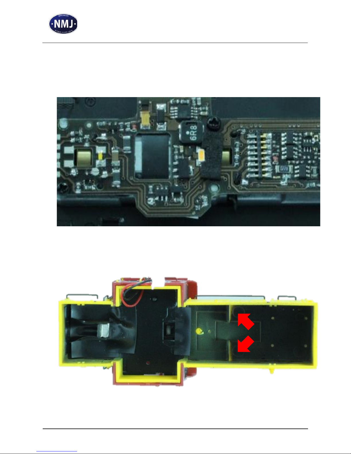
Half of the small adhesive tape from the original board can be used
to mask the side lighting of the LEDs of the central head lights.
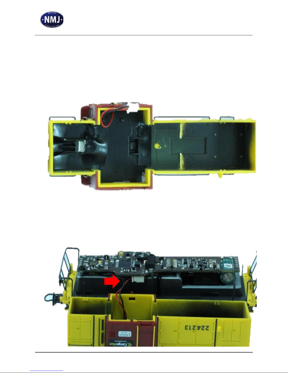
Before reassembling the housing, removal of 2 small inside walls (1)
is necessary to assure the required space for the replacement board.
1
Page 16
SKD224 replacement board
Assembly Manual
Document
Version
0.1.6
Page 16 of 46
This operation has to be performed using a cutter and a small plier.
The 2 interior walls must be cut with extreme care as close as
possible to the housing external wall without damaging it. After the
operation, clear the debris.
Insert the cabin light connector to the counterpart in the replacement
board.
Page 17
SKD224 replacement board
Assembly Manual
Document
Version
0.1.6
Page 17 of 46
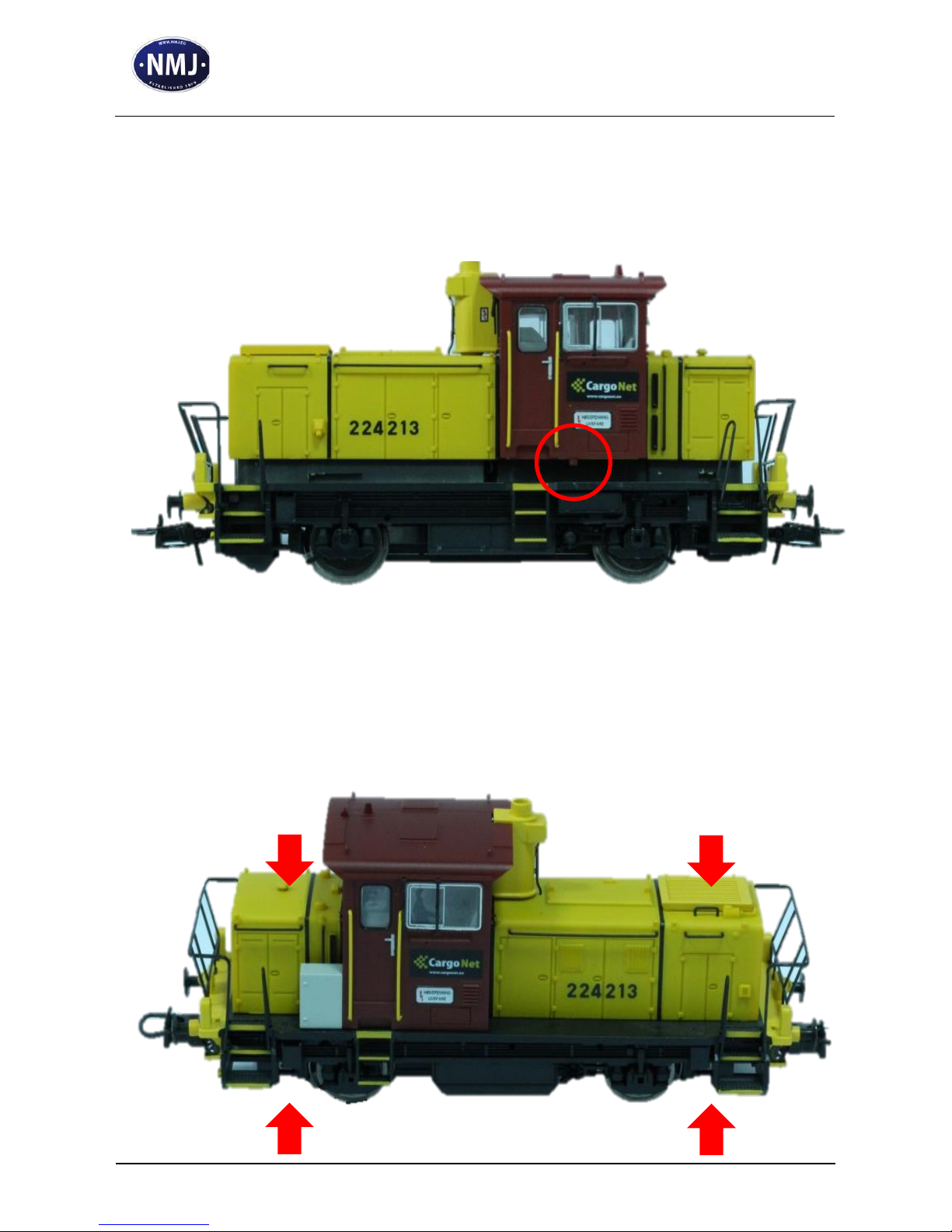
Insert the housing over the chassis, and press down until the plastic
ears fit the recesses of the chassis. The plastic ears of the cabin also
have to be fitted to the base plate.
After the housing is in its place, press the base plate in upper
direction while fitting the cabin plastic ears, till there is no distance
between the base plate and the housing.
Page 18
SKD224 replacement board
Assembly Manual
Document
Version
0.1.6
Page 18 of 46
8. Replacement of the wheels
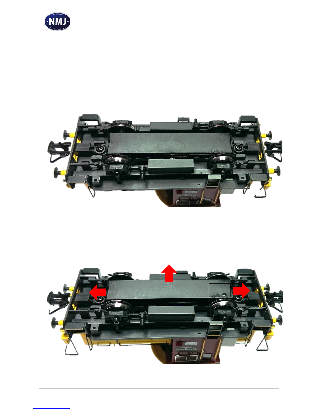
For the wheels/axles replacement, turn the locomotive upside down,
and place it on a stable surface to avoid falling on its side.
Pull the plastic ears on both sides of the base plate with a small
screwdriver to release it from the chassis (1). Lift the base plate in
upper direction (2).
1 1 2
Page 19
SKD224 replacement board
Assembly Manual
Document
Version
0.1.6
Page 19 of 46
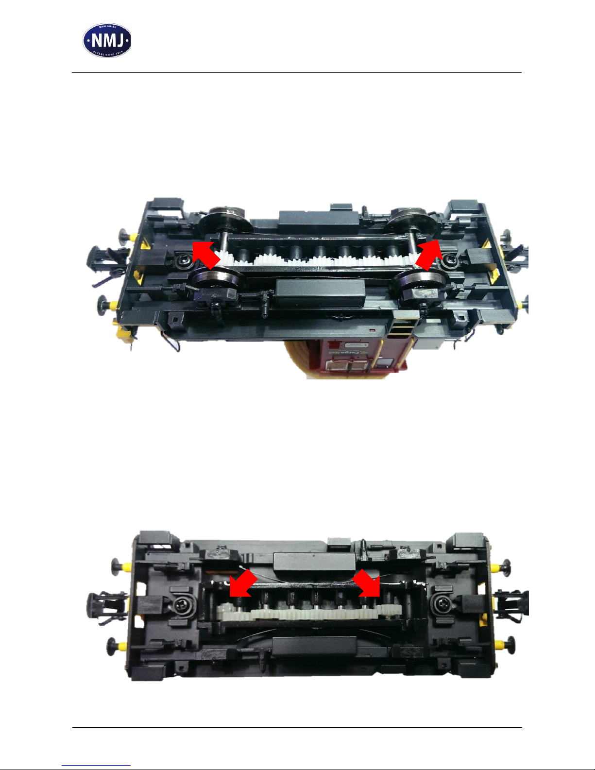
Remove the 2 original axles with the plastic toothed wheels from the
chassis. The axle’s assembly keeps the current pickups pressed to the
wheels, while removing them the current pickups will depart from
the chassis.
At this point since there is access to the gearbox, it could be a good
idea to apply some grease over the wheels if needed. However, this
can be done at a later time too. You can use Roco type grease part
number 10905.
Page 20
SKD224 replacement board
Assembly Manual
Document
Version
0.1.6
Page 20 of 46
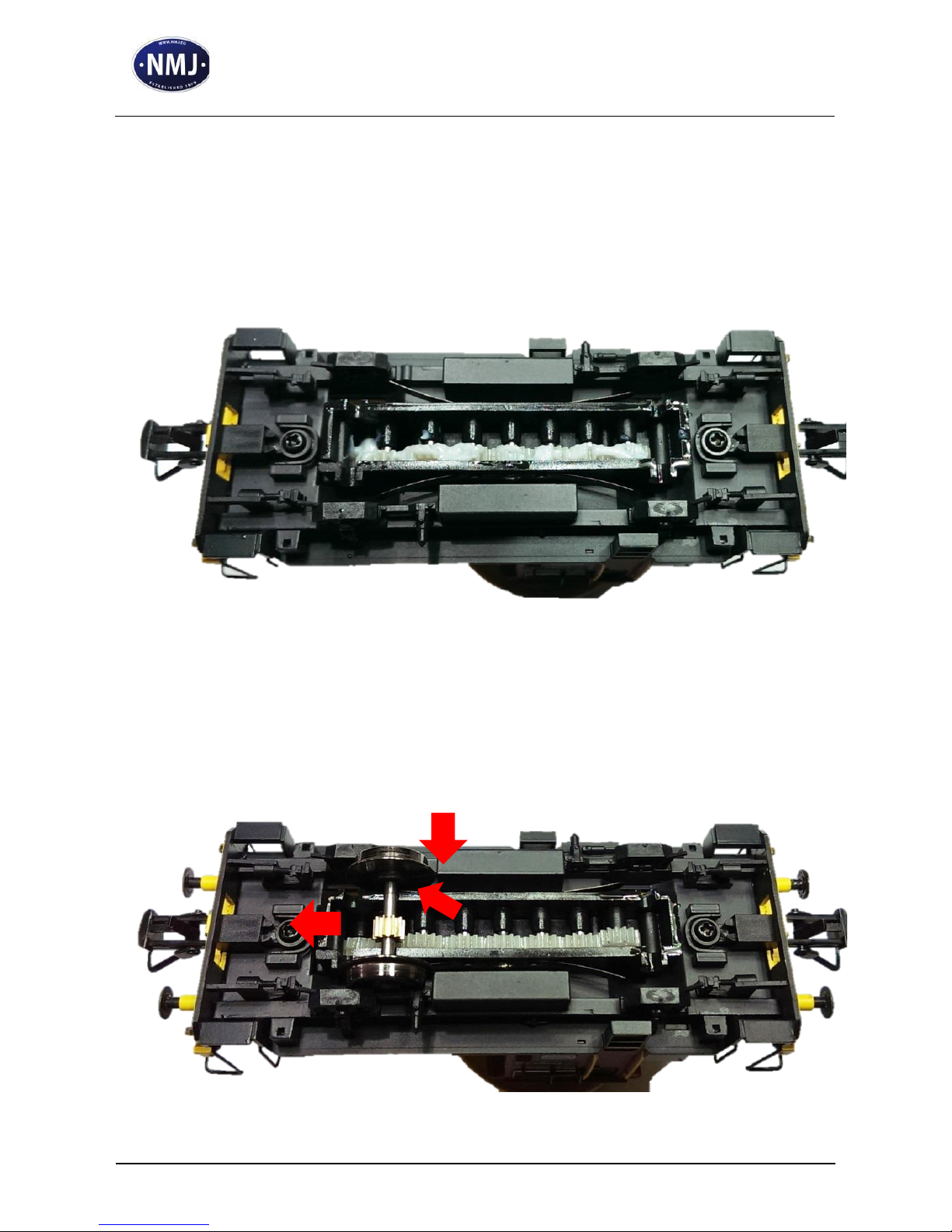
In the illustration an exaggerated quantity of grease is applied for
exemplification. Use the grease in a moderate quantity.
Apply it also on the intermediary toothed wheels too.
Insert the replacement axles with the brass toothed wheels. They
must be inserted starting from the inner side of the chassis (1),
moved to the correct position (2) while pressing the elastic current
pickups to touch the wheels from their inner side (3).
2 1 3
Page 21
SKD224 replacement board
Assembly Manual
Document
Version
0.1.6
Page 21 of 46
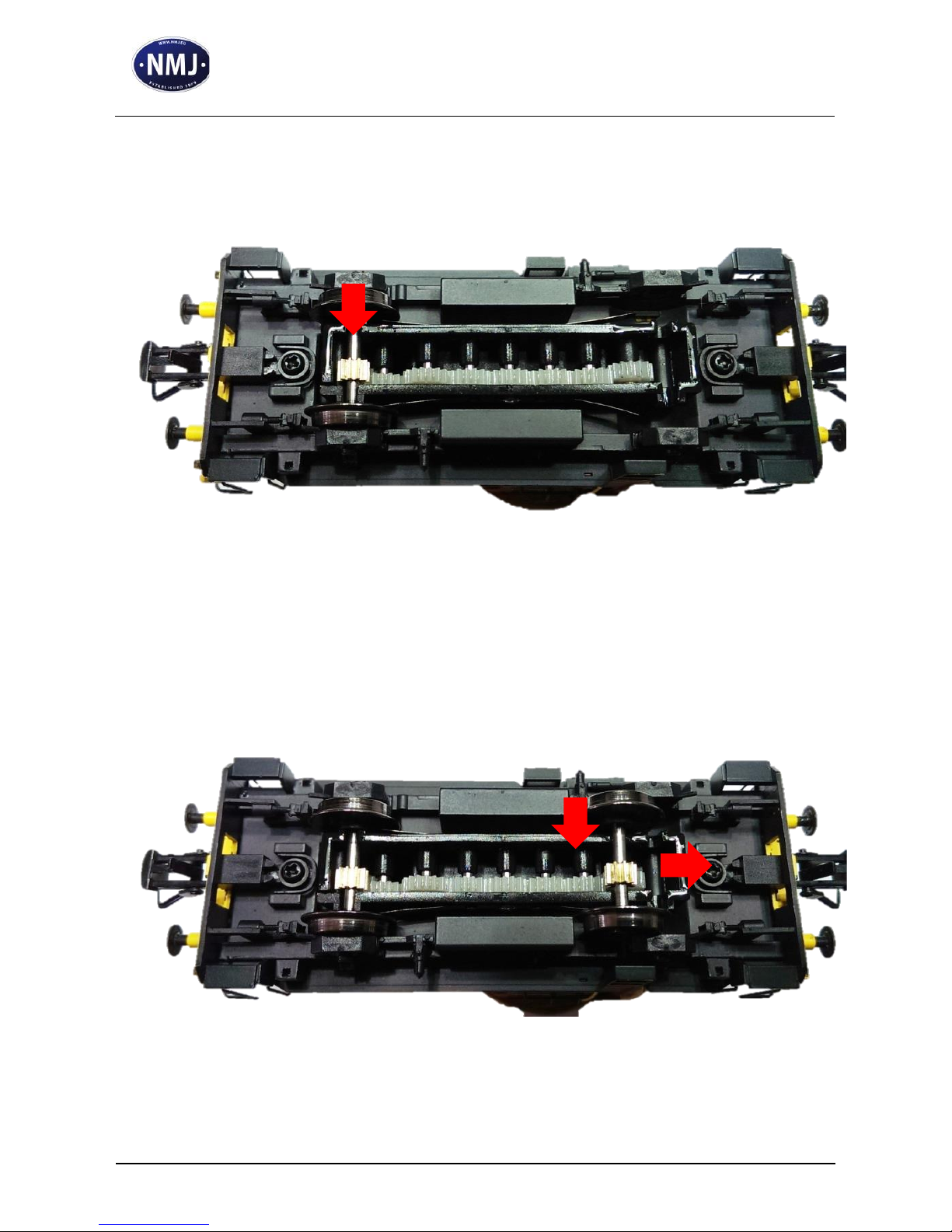
Press the axles in down direction when they are in the correct
position.
Continue with the insertion of the second axle (1) and move it to the
correct position (2).
1
2
Page 22
SKD224 replacement board
Assembly Manual
Document
Version
0.1.6
Page 22 of 46
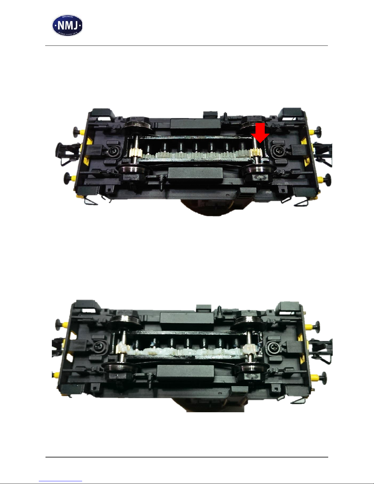
Press it down, to fit perfectly in the recess. Please take extreme care
about the correct positioning of the axles/wheels, since they have a
major influence over the running performance of the locomotive.
The grease can be applied also at this stage. As it is mentioned, use a
moderate quantity.
Page 23

SKD224 replacement board
Assembly Manual
Document
Version
0.1.6
Page 23 of 46
Drop a small quantity of fine mechanical oil at each axle/chassis
contact surface. Please use good quality oil, as the Roco 10906.
Place the base plate over the gearbox/chassis, and press it in down
direction at both sides to close it completely.
Page 24
SKD224 replacement board
Assembly Manual
Document
Version
0.1.6
Page 24 of 46
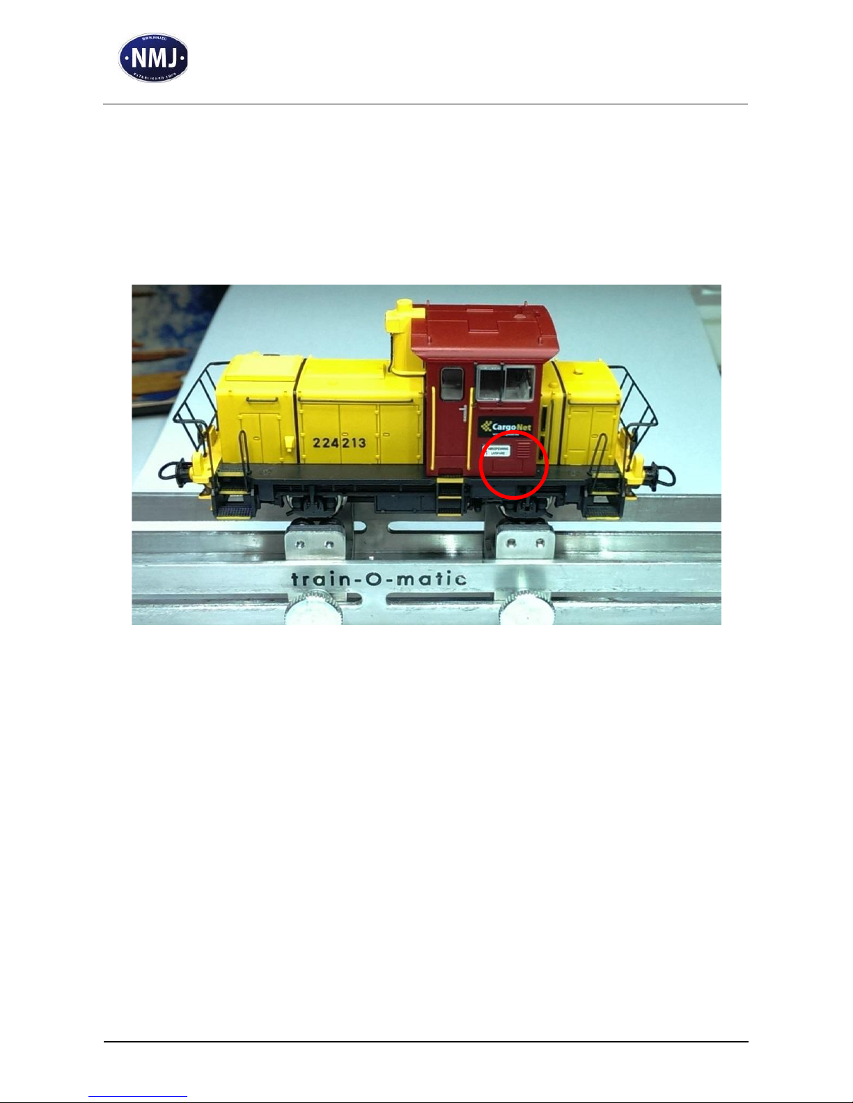
After the wheels/axles replacement, we recommend to drive the
locomotive in both forward and reverse direction for about 20-30
minutes.
A Roller Tester device can be used for this operation.
Page 25

SKD224 replacement board
Assembly Manual
Document
Version
0.1.6
Page 25 of 46
9. Decoder settings
The factory default setting maps the F0 function direction dependent
to the front and rear lights (FL and RL), and the F1 function to the
cabin light (AUX1/Out3).
FL front side high beam reflector (Out1)
RL rear side high beam reflector (Out2)
AUX1 cabin interior light (Out3)
AUX2 Not Used by default, connected
to the optional electrical coupler
outputs at both ends of the board (Out4)
The light intensity of the front/rear side high beam reflector and the
cabin light can be changed in CV48-49-50. In the factory settings,
these are configured for maximum intensity.
The decoder is preset for 28/128 speed step operation, no dc mode.
To take the full advantage of the BEMF motor control, we
recommend driving your locomotive with 128 speed steps. The
RailCom transmitter is sending the locomotive address in broadcast
mode. By default, the following function mappings are valid:
F3 shunting speed
F4 acceleration / deceleration OFF
F5 constant braking distance OFF
These mappings can be changed by altering the CVs 33-47. The
stopping configuration (CV27) by default has active only the Zero
Speed Brake option. Electrical coupler, ABC braking and penduling /
push-pull operation is disabled.
Page 26

SKD224 replacement board
Assembly Manual
Document
Version
0.1.6
Page 26 of 46
10. Programming tips
The SPP timeout is set by default to its maximum value 255, which
results in a ~ 4 second autonomy of the decoder in case of a DCC
power failure. This is useful, but has it’s withdraw: the locomotive
will be uncontrollable till this time expires. To avoid this, the SPP
timeout settled in CV123 can be decreased till a convenient value.
The Output4 (AUX2) of the decoder can be used for switching an
optional electrical coupler. First of all, we have to map a function to
this output (CVs 33-to 47). For example mapping F6 for the
electrical coupler will be made by changing the CV41 from the
default 0 value to 8.
Then we have to activate the coupler effect on the Output4 (AUX2).
This will be done by specifying in CV118 the Output4. Write in
CV118 the value 4.
The electrical coupler effect can be configured for only pwm action
(CV124=0, default value), or for some specific couplers which need
a full powered drive signal for a certain amount of time, and pwm
after the coupler is activated (CV124=1).
During the coupler operation the locomotive can be configure for the
typical “waltzer” (back, kick, and forward) movement. The back
movement and kick time is specified in CV119, while the forward
moving time and speed in CV120 and CV121. The settings of these
CVs can be done in several iterations by trial. During this coupling
operation the directional headlights of the locomotive will be not
switched. This “waltzer” movement is valid only if one of the 4
outputs is configured for coupler effect.
The Constant Braking Distance (CBD) is active by default (CV27
bit7 = 1). This will be taken inconsideration if the Zero Speed Brake
(active by default) or ABC braking (inactive by default) is requested.
Page 27

SKD224 replacement board
Assembly Manual
Document
Version
0.1.6
Page 27 of 46
The stopping distance should be determined at maximum speed step.
This can be done by altering the default 3 value of CV137 to 1,
which means the shortest possible stop distance (this distance
depends on the locomotive mechanical construction and gear box
configuration). This can be increased using a higher value for
CV137, and/or applying a braking delay in CV138. CV138=0 means
no braking delay applied over the stopping distance. These setting
must be done in several iteration by trial and error. In braking
condition, the locomotive will decelerate according to the constant
braking distance, and not base on CV4 (deceleration rate). However,
changing the speed of the locomotive (not to zero speed) will use the
deceleration rate settled in CV4. The constant braking distance can
be switched off with the F5 function (default configuration). The
function mapping can be changed altering CV116.
The stopping condition of the locomotive can be requested with the
help of ABC braking modules. The activation of this option is made
in CV27, bit0 (on right rail) and bit1 (on left rail). Either one or both
of these options can be used. If there is an uncertain situation while
detecting the ABC sections, the sensitivity of the ABC braking sector
detector can be increased by higher value than the default 15 in
CV134. Combining the ABC braking with the constant braking
distance will stop your locomotive in an exact position.
The locomotive can perform a so called penduling / push-pull
operation. For doing this, two braking sector must be present at both
ends of a straight track. The ABC braking must be configured in
CV27 for both directions (right and left rail too). The locomotive will
run from end A to end B of the track, where it will detects the
braking condition, will stop, and will wait till the waiting time
specified in CV133 will elapse. Then it will start to run in reverse
direction till it reaches end A, where it will stop again, wait, and so
on. If during this operation a new speed step command is sent to the
decoder from the central station, it will override the penduling
Page 28

SKD224 replacement board
Assembly Manual
Document
Version
0.1.6
Page 28 of 46
operation, and the locomotive can be controlled manually. If the
constant braking distance is active during the penduling operation,
the stopping of the locomotive at A/B ends will be done according to
the specified braking distance.
11. Analog operation
The analog operation of the SKD224 replacement board is not
activated by default to allow the operation of the SPP circuit.
However, the activation of the DC operation can be made by altering
the default CV29 value. Changing CV29 from the default value of 10
to 14 will activate the DC operation, but in the same time it will
deactivate the SPP.
12. Notes
Page 29
SKD224 replacement board
Assembly Manual
Document
Version
0.1.6
Page 29 of 46
13. CV Table
In the table below you will find the complete list of configuration variables (CVs) of the DCC decoder
built in the SKD224 replacememt board. We recommend to change the default values only if you know their
function. Wrong settings can have negative effect ower the performance of the locomotive, or can cause nonexpected actions to the DCC commands sent by the command station. The CV No. column contains the
number of the configuration variables, while the Value Range contains the valid range of values for each of
the CVs. The Default Value column contains the factory default values for each CV optimised for the
SKD224 (after performing a decoder reset each CV will contain this value). The Description column will
give you a brief description of each of the CVs. To perform a decoder reset (in case of wrong CV settings)
please write any numerical value to CV8.
CV
Default
Value
Value
Range
Description
1 3 0-127
Decoder Adresse Short, 7 bits
2 4 1-127
Vstart
3 7 0-63
Acceleration Rate 0=Fastest acceleration
4 5 0-63
Deceleration Rate 0=Fastest deceleration
5
60
1-127
Vhigh
6
30
0-127
Vmid, recommended value = [25%-75%] Vhigh
Page 30
SKD224 replacement board
Assembly Manual
Document
Version
0.1.6
Page 30 of 46
7 1 -
Software Version (only readable)
8
78 - Manufactured ID/RESET (readable 78 = train-O-matic, any written value
will reset the decoder to the factory default values
9 3 0-9
Motor Control Algorithm, 0-8
User defined = 9 (see CV 60)
13 0 0-255
Analog Mode, Alternate Mode Function Status F1-F8
Bit 0 = 0(0): F1 not active in Analog mode
= 1(1): F1 active in Analog mode
Bit 1 = 0(0): F2 not active in Analog mode
= 1(2): F2 active in Analog mode
Bit 2 = 0(0): F3 not active in Analog mode
= 1(4): F3 active in Analog mode
Bit 3 = 0(0): F4 not active in Analog mode
= 1(8): F4 active in Analog mode
Bit 4 = 0(0): F5 not active in Analog mode
= 1(16): F5 active in Analog mode
Bit 5 = 0(0): F6 not active in Analog mode
= 1(32): F6 active in Analog mode
Bit 6 = 0(0): F7 not active in Analog mode
= 1(64) F7 active in Analog mode
Bit 7 = 0(0): F8 not active in Analog mode
= 1(255): F8 active in Analog mode
Page 31
SKD224 replacement board
Assembly Manual
Document
Version
0.1.6
Page 31 of 46
14
3=
1+
2
0-255
Analog Mode, Alternate Mode Function. Status F0f,F0r, F9-F14,
Bit 0 = 0(0): F0f not active in Analog mode
= 1(1): F0f active in Analog mode
Bit 1 = 0(0): F0r not active in Analog mode
= 1(2): F0r active in Analog mode
Bit 2 = 0(0): F9 not active in Analog mode
= 1(4): F9 active in Analog mode
Bit 3 = 0(0): F10 not active in Analog mode
= 1(8): F10 active in Analog mode
Bit 4 = 0(0): F11 not active in Analog mode
= 1(16): F11 active in Analog mode
Bit 5 = 0(0): F12 not active in Analog mode
= 1(32): F12 active in Analog mode
Bit 6 = 0(0): F13 not active in Analog mode
= 1(64) F13 active in Analog mode
Bit 7 = 0(0): F14 not active in Analog mode
= 1(255): F14 active in Analog mode
15 0 0-7
LockValue: Enter the value to match Lock ID in CV16 to unlock CV
programming. No action and ACK will be performed by the decoder when
LockValue is different from LockID. In this situation only CV15 write is
allowed.
Page 32
SKD224 replacement board
Assembly Manual
Document
Version
0.1.6
Page 32 of 46
16 0 0-7
LockID: To prevent accidental programming use unique ID number for
decoders with same address (0..7) For example: 1-loco decoder, 2-sound
decoder, 3-function decoder, …
17
192
192-255
Extended Address, Address High
18 3 0-255
Extended Address, Address Low
19 0 0-127
Consist Address
If CV #19 > 0: Speed and direction is governed by this
consist address (not the individual address in CV #1 or
#17+18); functions are controlled by either the consist
address or individual address, see CV’s #21 + 22.
21 0 0-255
Functions defined here will be controlled by the consist address.
Bit 0 = 0(0): F1 controlled by individual address
= 1(1): …. by consist address
Bit 1 = 0(0): F2 controlled by individual address
= 1(2): …. by consist address
Bit 2 = 0(0): F3 controlled by individual address
= 1(4): …. by consist address
Bit 3 = 0(0): F4 controlled by individual address
= 1(8): …. by consist address
Bit 4 = 0(0): F5 controlled by individual address
= 1(16): …. by consist address
Bit 5 = 0(0): F6 controlled by individual address
Page 33
SKD224 replacement board
Assembly Manual
Document
Version
0.1.6
Page 33 of 46
= 1(32): …. by consist address
Bit 6 = 0(0): F7 controlled by individual address
= 1(64): …. by consist address
Bit 7 = 0(0): F8 controlled by individual address
= 1(255): …. by consist address
22 0 0-63
Functions defined here will be controlled by the consist address.
Bit 0 = 0(0): F0 (fwd.) controlled by individual address
= 1(1): …. by consist address
Bit 1 = 0 (0): F0 (rev.) controlled by individual address
= 1(2): …. by consist address
Bit 2 = 0(0): F9 controlled by individual address
= 1(4): …. by consist address
Bit 3 = 0(0): F10 controlled by individual address
= 1(8): …. by consist address
Bit 4 = 0(0): F11 controlled by individual address
= 1(16): …. by consist address
Bit 5 = 0(0): F12 controlled by individual address
= 1(32): …. by consist address
27
128=
0-7
Decoder Automatic Stopping Configuration
Bit 0 = 0(0): Constant Braking Distance on right rail disabled
= 1(1): Constant Braking Distance on right rail enabled
Page 34
SKD224 replacement board
Assembly Manual
Document
Version
0.1.6
Page 34 of 46
128
Bit 1 = 0 (0): Constant Braking Distance on left rail disabled
= 1(2): Constant Braking Distance on left rail enabled
Bit 3 = 0(0): DC Braking disabled
= 1(8): DC Braking enabled
Bit 7 = 0(0): STOP/Zero Speed Braking disabled
= 1(128):STOP/Zero Speed Braking enabled
28 1 1-3
RailCom Configuration
Bit 0 = 0(0): Address broadcast on Channel 1 disabled
= 1(1): Address broadcast on Channel 1 enabled
Bit 1 = 0(0): Data transmission on Channel 2 disabled
= 1(2): Data transmission on Channel 2 enabled
29
10=
2+
8
0-63
Configuration Data
Bit 0 = 0(0): Locomotive Direction normal
= 1(1): Locomotive Direction reversed
Bit 1 = 0(0): 14 speed steps
= 1(2): 28 /128 speed steps
Bit 2 = 0(0): Power Source Conversion NMRA Digital Only (only DCC)
= 1(4): Power Source Conversion Enabled (DC + DCC)
Bit 3 = 0(0): RailCom disabled
= 1(8): Railcom enabled
Bit 4 = 0(0): speed table set by configuration variables #2,#5, and #6
= 1(32): Speed Table set by configuration variables #66-#95
Page 35
SKD224 replacement board
Assembly Manual
Document
Version
0.1.6
Page 35 of 46
Bit 5 = 0(0): one byte addressing (short addressing)
= 1(64): two byte addressing (extended/long addressing)
Bit 6 -Not Used
Bit 7 -Not Used
30 0 0-7
Error CV. If the read out value is “1”, an overcurrent event occurred since
the last reset. The value can be cleared with programming “0” to CV30
Error Information (combination of each values are possible):
0-No error
1-Motor Short Protection
2-Aux Output Short Protection
4-Overtemperature
33
1=
1
0-15
F0, Forward move mapping
Bit 0 = 0(0): Out1 not active on F0 forward
= 1(1): Out1 active on F0 forward
Bit 1 = 0(0): Out2 not active on F0 forward
= 1(2): Out2 active on F0 forward
Bit 2 = 0(0): Out3 not active on F0 forward
= 1(4): Out3 active on F0 forward
Bit 3 = 0(0): Out4 not active on F0 forward
= 1(8): Out4 active on F0 forward
34
2= 0-15
F0, Backward move mapping
Bit 0 = 0(0): Out1 not active on F0 backward
Page 36
SKD224 replacement board
Assembly Manual
Document
Version
0.1.6
Page 36 of 46
2
= 1(1): Out1 active on F0 backward
Bit 1 = 0(0): Out2 not active on F0 backward
= 1(2): Out2 active on F0 backward
Bit 2 = 0(0): Out3 not active on F0 backward
= 1(4): Out3 active on F0 backward
Bit 3 = 0(0): Out4 not active on F0 backward
= 1(8): Out4 active on F0 backward
35
4=
4
0-15
F1, Forward move mapping
Bit 0 = 0(0): Out1 not active on F1 forward
= 1(1): Out1 active on F1 forward
Bit 1 = 0(0): Out2 not active on F1 forward
= 1(2): Out2 active on F1 forward
Bit 2 = 0(0): Out3 not active on F1 forward
= 1(4): Out3 active on F1 forward
Bit 3 = 0(0): Out4 not active on F1 forward
= 1(8): Out4 active on F1 forward
36
4=
0-255
F1, Backward move mapping
Bit 0 = 0(0): Out1 not active on F1 backward
= 1(1): Out1 active on F1 backward
Bit 1 = 0(0): Out2 not active on F1 backward
= 1(2): Out2 active on F1 backward
Bit 2 = 0(0): Out3 not active on F1 backward
Page 37
SKD224 replacement board
Assembly Manual
Document
Version
0.1.6
Page 37 of 46
4
= 1(4): Out3 active on F1 backward
Bit 3 = 0(0): Out4 not active on F1 backward
= 1(8): Out4 active on F1 backward
37
0=
0-255
F2 mapping
Bit 0 = 0(0): Out1 not active on F2
= 1(1): Out1 active on F2
Bit 1 = 0(0): Out2 not active on F2
= 1(2): Out2 active on F2
Bit 2 = 0(0): Out3 not active on F2
= 1(4): Out3 active on F2
Bit 3 = 0(0): Out4 not active on F2
= 1(8): Out4 active on F2
38 0 0-255
F3 mapping
Bit 0 = 0(0): Out1 not active on F3
= 1(1): Out1 active on F3
Bit 1 = 0(0): Out2 not active on F3
= 1(2): Out2 active on F3
Bit 2 = 0(0): Out3 not active on F3
= 1(4): Out3 active on F3
Bit 3 = 0(0): Out4 not active on F3
= 1(8): Out4 active on F3
39 0 0-255
F4 mapping
Page 38
SKD224 replacement board
Assembly Manual
Document
Version
0.1.6
Page 38 of 46
Bit 0 = 0(0): Out1 not active on F4
= 1(1): Out1 active on F4
Bit 1 = 0(0): Out2 not active on F4
= 1(2): Out2 active on F4
Bit 2 = 0(0): Out3 not active on F4
= 1(4): Out3 active on F4
Bit 3 = 0(0): Out4 not active on F4
= 1(8): Out4 active on F4
40 0 0-255
F5 mapping
Bit 0 = 0(0): Out1 not active on F5
= 1(1): Out1 active on F5
Bit 1 = 0(0): Out2 not active on F5
= 1(2): Out2 active on F5
Bit 2 = 0(0): Out3 not active on F5
= 1(4): Out3 active on F5
Bit 3 = 0(0): Out4 not active on F5
= 1(8): Out4 active on F5
41 0 0-255
F6 mapping
Bit 0 = 0(0): Out1 not active on F6
= 1(1): Out1 active on F6
Bit 1 = 0(0): Out2 not active on F6
= 1(2): Out2 active on F6
Page 39
SKD224 replacement board
Assembly Manual
Document
Version
0.1.6
Page 39 of 46
Bit 2 = 0(0): Out3 not active on F6
= 1(4): Out3 active on F6
Bit 3 = 0(0): Out4 not active on F6
= 1(8): Out4 active on F6
42 0 0-255
F7 mapping
Bit 0 = 0(0): Out1 not active on F7
= 1(1): Out1 active on F7
Bit 1 = 0(0): Out2 not active on F7
= 1(2): Out2 active on F7
Bit 2 = 0(0): Out3 not active on F7
= 1(4): Out3 active on F7
Bit 3 = 0(0): Out4 not active on F7
= 1(8): Out4 active on F7
43 0 0-255
F8 mapping
Bit 0 = 0(0): Out1 not active on F8
= 1(1): Out1 active on F8
Bit 1 = 0(0): Out2 not active on F8
= 1(2): Out2 active on F8
Bit 2 = 0(0): Out3 not active on F8
= 1(4): Out3 active on F8
Bit 3 = 0(0): Out4 not active on F8
= 1(8): Out4 active on F8
Page 40
SKD224 replacement board
Assembly Manual
Document
Version
0.1.6
Page 40 of 46
44 0 0-255
F9 mapping
Bit 0 = 0(0): Out1 not active on F9
= 1(1): Out1 active on F9
Bit 1 = 0(0): Out2 not active on F9
= 1(2): Out2 active on F9
Bit 2 = 0(0): Out3 not active on F9
= 1(4): Out3 active on F9
Bit 3 = 0(0): Out4 not active on F9
= 1(8): Out4 active on F9
45 0 0-255
F10 mapping
Bit 0 = 0(0): Out1 not active on F10
= 1(1): Out1 active on F10
Bit 1 = 0(0): Out2 not active on F10
= 1(2): Out2 active on F10
Bit 2 = 0(0): Out3 not active on F10
= 1(4): Out3 active on F10
Bit 3 = 0(0): Out4 not active on F10
= 1(8): Out4 active on F10
46 0 0-255
F11 mapping
Bit 0 = 0(0): Out1 not active on F11
= 1(1): Out1 active on F11
Bit 1 = 0(0): Out2 not active on F11
Page 41
SKD224 replacement board
Assembly Manual
Document
Version
0.1.6
Page 41 of 46
= 1(2): Out2 active on F11
Bit 2 = 0(0): Out3 not active on F11
= 1(4): Out3 active on F11
Bit 3 = 0(0): Out4 not active on F11
= 1(8): Out4 active on F11
47 0 0-255
F12 mapping
Bit 0 = 0(0): Out1 not active on F12
= 1(1): Out1 active on F12
Bit 1 = 0(0): Out2 not active on F12
= 1(2): Out2 active on F12
Bit 2 = 0(0): Out3 not active on F12
= 1(4): Out3 active on F12
Bit 3 = 0(0): Out4 not active on F12
= 1(8): Out4 active on F12
48
255
0-255
Out 1 Light intensity, [1-255]
49
255
0-255
Out 2 Light intensity, [1-255]
50
255
0-255
Out 3 Light intensity, [1-255]
51
255
0-255
Out 4 Light intensity, [1-255]
56 0 0-1
Save last Function state if CV value = 1
60 3 0-7 and
128-135
Motor, Back EMF measurement Delay
value of 0 or 128 swithes BackEMF Off, value>0 or > 128 changes the
Page 42
SKD224 replacement board
Assembly Manual
Document
Version
0.1.6
Page 42 of 46
BEMF measurement Delay. Delay(ms)=0.75+CV Value*0.25
Bit7=0 uses 32kHz PWM (CV range 0-7)
Bit7=1 uses 16kHz PWM ( CV range 128-135)
61
80
0-255
PID P constant
62
120
0-255
PID I constant
63
40
0-255
PID D constant
67 2 1-127
Speed Table 1-28 ST[1] 1 position speed value
…..
Throttle position speed mapping values, ex. 1 position=2 speed, 28
position=120 speed
94
120
1-127
ST[28], 28 position speed value
105
0
0-255
USER data, freely configurable. It is not cleared after a decoder reset
106
0
0-255
USER data, freely configurable. It is not cleared after a decoder reset
112
15
1-127
Fade ON effect on outputs, ex.:1=8ms, 15=120ms 125=1000ms
113
3
1-127
Fade OFF effect on outputs, ex.:1=8ms, 15=120ms 125=1000ms
114
4
0-255
Shunting speed, Function mapping F1-F8, F3 default (bit 0 is mapping F1,
bit 7 is mapping F8). Mapping is possible only for F1-F8
115
8
0-255
Switch Off Acceleration Deceleration, Function mapping, F4 default (bit 0
is mapping F1, bit 7 is mapping F8). Mapping is possible only for F1-F8
116
16
0-255
Disable Constant Braking Distance, Function mapping, F5 default (bit 0 is
mapping F1, bit 7 is mapping F8). Mapping is possible only for F1-F8
117
0
0-15
Bit 0 = 0(0): Out1 could be dimmed and faded
Page 43
SKD224 replacement board
Assembly Manual
Document
Version
0.1.6
Page 43 of 46
= 1(1): continues signal with no fading on Out1
Bit 1 = 0(0): Out2 could be dimmed and faded
= 1(2): continues signal with no fading on Out2
Bit 2 = 0(0): Out3 could be dimmed and faded
= 1(4): continues signal with no fading on Out3
Bit 3 = 0(0): Out4 could be dimmed and faded
= 1(8): continues signal with no fading on Out4
118
0
0-4
Electrical Coupler Output mapping for the 1-4 outputs. Only one of the
outputs can be configured as ECoupler Output
CV118 = 0, None of the AUX selected for ECoupler operation
CV118 = 1, Out1 selected for ECoupler operation
CV118 = 2, Out2 selected for ECoupler operation
CV118 = 3, Out3 selected for ECoupler operation
CV118 = 4, Out4 selected for ECoupler operation
119
50
0-255
Electrical Coupler, Kick_time = Val*8ms, ex: 400ms=50*8ms
120
50
0-255
Decoupling, Locomotive move Time=Val*8ms, ex: 400ms=50*8ms
121
50
0-255
Decoupling, Locomotive moving speed
122
1
0-1
Second Configuration,
Bit 0 = 0(0): SUSI interface disabled
= 1(1): SUSI Interface enabled
Bit 1 = 0(0): Push Pull Operation disabled
= 1(2): Push Pull Operation enabled
Page 44
SKD224 replacement board
Assembly Manual
Document
Version
0.1.6
Page 44 of 46
123
255
0-255
SPP (Smart Power Pack) Timeout=16ms*Value Ex: =16ms*255=~4s
124
0
0-1
ECoupler Mode
CV124 = 0, PWM Output
CV124 = 1, Full Output startup + PWM Output for sustaining the coupler
on selected A in CV118
126
102
0-255
SUSI CV transport, SUSI CV=800+Value
127
0
0-255
SUSI DATA transport, Data write to CV=800+cv126
131
Chip temperature read out (the value is expressed in degrees Celsius. The
precision of the readout is +/- 2 degrees). Prior to the readout the F5
function must be switched On and Off
132
100
60-120
Temperature Limit for the temperature protection (value in degrees
Celsius)
133
10
0-255
Penduling / Push-Pull Wait Time
134
15
0-31
ABC Breaking Sensitivity
137
3
0-15
Brake Distance configuration
0-No brake
1-15 Braking rate, the CV value influences the Constant Braking Distance,
CV137=1 means the Shortest Braking Distance from maximum Speed to
STOP. Increase the CV value to increase the braking distance.
Distance=Value * Shortest Breaking Distance
Page 45
SKD224 replacement board
Assembly Manual
Document
Version
0.1.6
Page 45 of 46
138
25
0-255
Brake Delay Configuration
CV138= 0 means no Brake Delay. To increase breaking distance above the
value configured in CV138, increase in small amounts the value of CV65,
which will delay the start of the braking, resulting in a longer braking path.
Brake Delay = CV138 Value * 8ms (ms)
Extra Distance = MaxSpeed * BrakeDelay
Ex: 200ms(delay)=8(ms)*25(CV value)
Page 46
SKD224 replacement board
Assembly Manual
Document
Version
0.1.6
Page 46 of 46
NMJ - Norsk Modelljernbane AS
Copyright © 2016 NMJ
All rights reserved
The information in this document is subject to change without
notice
Ensjøveien 7,
0655 Oslo
Tel: (+47) 64 84 57 30
Fax: (+47) 64 84 57 39
www.nmj.no [email protected]
 Loading...