

Page 1
UDO LP400
USER GUIDEv5.2
Presented by
100 Providence Pike
North Smithfield, RI 02896
(800) 453-2727
www.nationalmarker.com
Page 2
UDO LP400 User Guide
_____________________________________________________________________________________________________
Table of Contents
I. Product Description 3
II. Technical Support & Assistance 3
III. Switches, Indicators & Connections 4
IV. Setting-Up the UDO LP400 Printer 6
A. Installing Cables 6
B. Installing Vinyl Rolls 7
C. Installing Printer Ribbons 8
V. Loading UDO LP400 Software & Printer Driver 9
VI. Set-up Procedure for Printing on Continuous Vinyl 12
A. Default Settings & Adjustments 12
1. Label Dimensions 12
2. LP400 Printer Properties 13
a Advanced Setup 14
VII. Navigating the Toolbars 15
A. The Toolbox Toolbar 15
B. The Text Toolbar 16
C. The Alignment Toolbar 17
VIII. The Basics of Designing a Label 19
A. Inserting a Image 19
B. Inserting Text 20
C. Resizing & Positioning Objects 21
IX. Applications 21
A. Setting-Up Variables 21
B. Inversing 22
C. Rotating Text & Symbols 23
D. Curved Text 23
E. Importing Pictures 25
F. Multi-band Printing: Creating Large Signs & Labels 26
X. Common Applications 27
A. Directional Sign 27
B. Pipe Marker Sign 31
C. Inverted Text 35
D. Multi-band Printing 37
Troubleshooting 45
Maintenance 46
General Printer Specifications 47
LP400 User Guide (02/11) v5.2
2
Page 3

UDO LP400 User Guide
_____________________________________________________________________________________________________
I. Product Description
The UDO LP400 Labelmaker is a high-performance, thermal transfer sign and labeling
system designed for multiple labeling and marking applications including various
manufacturing, industrial, commercial, logistics and office applications.
The printer includes a highly-efficient memory management technology - True Speed -
and prints at a speed of 1 - 4 inches per second. The system comes complete with a
dedicated printer driver. The UDO LP400 Software enables users to quickly and easily
print a multitude of labels, including those requiring bar codes, specific fonts and
graphics, or any editing application (e.g. CorelDraw, Word) in a Windows environment.
The UDO LP400 enables organizations of all sizes to have a compact, cost-effective
labeling solution on their premises. Indeed, the ease with which the printer and software
can be set-up and installed makes this the perfect sign and labeling system for virtually
any organization.
This User's Guide has been prepared to assist you in understanding, operating and
maintaining your UDO LP400 so that you may utilize your new sign and labeling system
to its fullest capabilities.
If you require assistance with your UDO LP400 or would like to offer any comments or
suggestions, please contact NMC at the address below.
II. Technical Support & Assistance
NMC
Attn: UDO LP400 Technical Support
100 Providence Pike
North Smithfield, RI 02896
• UDO Hotline
(800) 453-2727
Monday – Friday; 8 am – 5 pm (Eastern Time)
• Fax-Help Service
(800) 338-0309
Attn: UDO Technical Support
• E-Mail:
• If you require assistance with any aspect of the software, simply click ‘Help’
and follow the instructions.
Please feel free to visit us on the web at: www.nationalmarker.com
LP400 User Guide (02/11) v5.2
3
Page 4
UDO LP400 User Guide
•
•
•
•
•
•
•
•
•
_____________________________________________________________________________________________________
III. Switches, Indicators and Connections
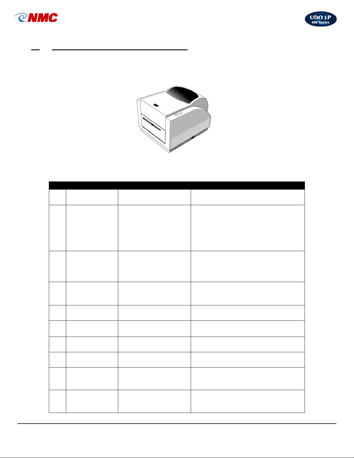
UDO LP 400 LABELMAKER
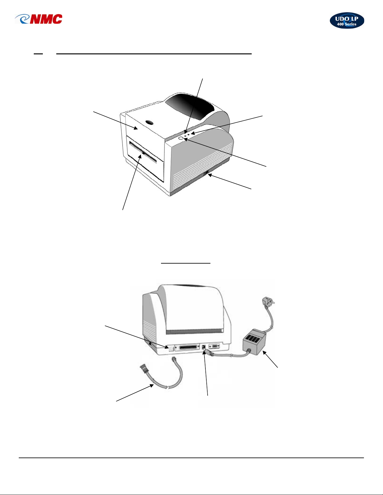
The table below summarizes the functions of the various printer switches (buttons),
indicators and connections (see diagrams on page 3).
No. Device Name Function Usage
1
2 FEED Button
3 READY Light
4 POWER Light
5
ON / OFF
Switch
Power Jack
Controls printer power
Advances vinyl &
ribbon
Shows the printer
status
Shows the power and
error status
Connects the power
adapter to the printer
On – Normal operating position
• Off – Loading media & ribbon
Press to advance label.
• Press & hold while turning on
printer to print out the self-test.
• Press to continue printing when
READY light is blinking.
• Press to resume printing.
Steady green light: the printer is
ready to operate.
• Blinking light: paused.
• Press ‘FEED’ button to continue.
Light off: printer power is off.
• Light on: printer power is on.
• Blinking light: printer error.
Power adapter plugs into the back
of the printer.
6
USB v2.0 Port
7 Top Cover
8
9
10
LP400 User Guide (02/11) v5.2
Cutter /
Discharge
USB Cable
Power Adapter
Communication port
Protects ribbon and
media
Cuts and discharges
labels
Connects PC to printer
Connects power to
printer
4
• Printer port for USB connection.
Access ribbon and media by lifting
cover.
Rotating, self-sharpening blade
trims and discharges labels.
Plug into computer USB port and
into printer to transfer information
from computer to printer.
To activate printer: Insert the plug
into the power source & the
opposite end into the power jack.
Page 5
UDO LP400 User Guide
g
_____________________________________________________________________________________________________
III. SWITCHES, INDICATORS & CONNECTIONS (cont.)
7. Top Cover
8. Cutter / Discharge
`
6. USB Port
3. READY Li
Back of Printer
5. Power Jack
9. USB Cable
ht
4. POWER Light
2. FEED button
1. ON / OFF Switch
10. Power Adapter
LP400 User Guide (02/11) v5.2
5
Page 6
UDO LP400 User Guide
_____________________________________________________________________________________________________
NOTICE
• This printer complies with the requirements in Part 15 of the FCC rules for a Class A
or B computing device.
• Do not place the printer near a heat source or near water.
• Do not attempt to disassemble the printer if it malfunctions.
• All rights reserved. No part of this document may be reproduced or issued to third
parties in any form without the express written permission of NMC – National Marker
Company.
• The material in this document is provided for general information and is subject to
change without notice.
* * * * * * * * * * * * * * * * * * * * * * * * * * * * * * *
IV. SETTING-UP THE UDO LP400 PRINTER
Begin by making certain the printer is on a solid, flat surface. Ensure there is sufficient
space above the printer so the top cover may be easily opened, allowing for easy
installation and removal of vinyl rolls and printer ribbons.
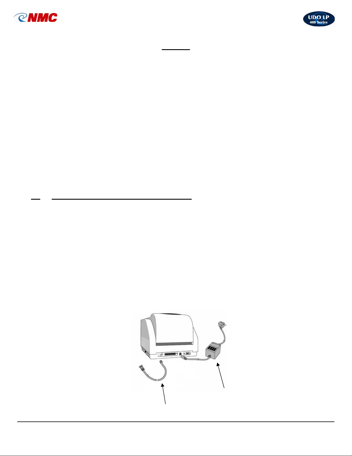
A. Installing Cables (Fig. 1)
(Be certain the printer is turned off while connecting the cables.)
1. Connect the power adapter to the printer but do not plug the power adapter into a
power outlet.
2. Connect the USB cable to the back of the printer as well as to the USB port
located on your computer.
Fig. 1
LP400 User Guide (02/11) v5.2
Power Adapter
USB Cable
6
Page 7
UDO LP400 User Guide
_____________________________________________________________________________________________________
B. Installing Vinyl Rolls (Figs. 2-4):
1. Select the desired vinyl roll and remove from packaging.
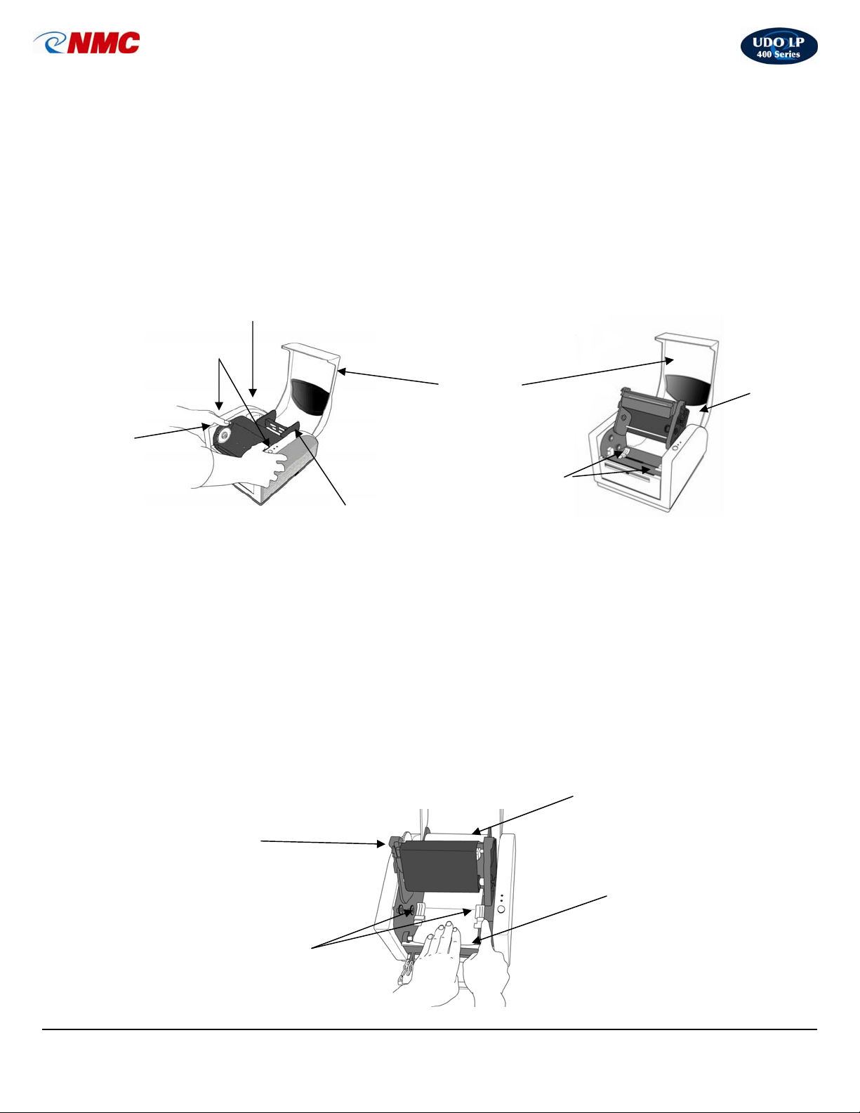
2. Open the printer lid and press down on the two (2) purple buttons to open the
Print Head (Fig. 2).
3. In the printer is a plastic black bar with guides at each end (Supply Holder)
(Fig. 2). Remove the white tape which is holding the bar in place. If installing a 4”
vinyl roll, remove the guides from the main bar. (Do not discard guides; they are
required when the vinyl roll is less than 4”.)
Purple Buttons
(Used to Open &
Close Print Head)
Purple
Ribbon
Advance
Wheel
Fig. 2
Fig. 4
Print Head in Closed Position
Printer Lid
Self-Centering
Vinyl Roll
Supply Holder
Guides
(Purple)
4. Insert the plastic black bar through the core of the vinyl roll and return the Supply
Holder to its place; make sure the start of the vinyl roll is directed towards the
front of the printer (refer to diagram inside the printer lid for specific loading
instructions.)
5. Located beneath the Print Head are two (2) purple Self-Centering Guides (Fig. 3).
Slide the guides apart as far as possible.
6. Hand feed the vinyl towards the front of the printer (Fig. 4). Feed the vinyl under
the Print Head and under the Centering Guides; proceed over the black roller bar
until vinyl begins to come through the Cutter/Discharge. While holding the vinyl
flat, move the Centering Guides back into the center position (as far as they can
go) to secure the vinyl in place.
Print
Head
(open)
Self-Centering Guides
(Purple)
Vinyl Roll
Black Roller & Black Metal Bar
Print Head
In
Open
Position
Fig. 3
LP400 User Guide (02/11) v5.2
7
Page 8
UDO LP400 User Guide
p
_____________________________________________________________________________________________________
C. Installing Printer Ribbons
1. Remove the printer ribbon from its packaging. (Note: The black, blue & red
ribbons have a blue outer casing; thus, they will need to be unwound until the
appropriate color is revealed.)
2. Open the Print Head (if not already open) (Fig. 2) by pressing down on the two
(2) purple buttons.
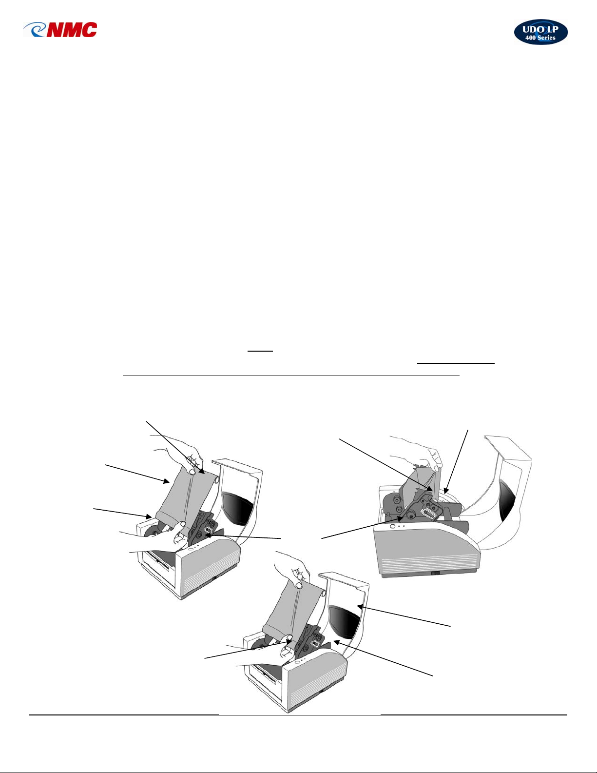
3. Locate the two (2) Ribbon Holders (Fig. 7). One Ribbon Holder is on the top of
the Print Head and one Ribbon Holder is on the bottom of the Print Head. The
right side of each of the Ribbon Holders is spring-loaded; the left side has a
wheel with a catch.
4. Slightly unroll the ribbon so the shiny side faces you (Fig. 5).
5. Unroll the core of the ribbon spool. The core containing the unused ribbon (full
roll) fits into the bottom Ribbon Holder which is spring loaded on the right side.
Align the ribbon core with the left side. The wheel on the left side has a catch.
Align the notch in the ribbon core with the catch and insert.
6. The smaller ribbon spool (empty) fits into the top Ribbon Holder which is spring
loaded on the right side. Align the ribbon core with the left side. The wheel on the
left side has a catch. Align the notch in the ribbon core with the catch and insert.
7. Use the purple Ribbon Advance Wheel on the left side (Fig. 2) to advance the
ribbon as tight as possible and the ribbon is wound firmly onto the top spool.
Take care to ensure that the ribbon is not creased or uneven.
8. Push the print head down firmly
9. Close the printer lid & plug the power adapter into an outlet.
Small Ribbon S
Shiny Side of Ribbon
(On Top – Facing you)
Large Ribbon Spool
(Full Roll – Unused Ribbon)
Fig. 5 Fig. 6
Bottom Ribbon Holder
(Right Side is Spring-Loaded)
Fig. 7
labels (located on the left and right side of the print head) and ensure that both
sides of the print head unit click into place (you should hear two clicks.)
ool
using the two (2) black tabs beneath the “Lock”
Bottom Roll Feeds
to the Top Roll
Ribbon
Holder
Spring Loaded
Ribbon Wheel
Ribbon Loading
Instructions
(Inside Top Cover)
Top Ribbon Holder
(Right Side is Spring-Loaded)
LP400 User Guide (02/11) v5.2
8
Page 9
UDO LP400 User Guide
_____________________________________________________________________________________________________
V. LOADING UDO LP400 SOFTWARE & PRINTER DRIVER
1. Connect power adaptor and USB cable to the printer.
2. Turn the printer ON; green “POWER” and “READY” light will come on.
3. Insert UDO LP400 Series software CD into your computer (the screen shown in
Step #4 will appear.)
NOTE: If your computer does not support “Autorun”, open ‘My Computer’,
double-click your ‘CD drive’, and double-click ‘start.exe’.
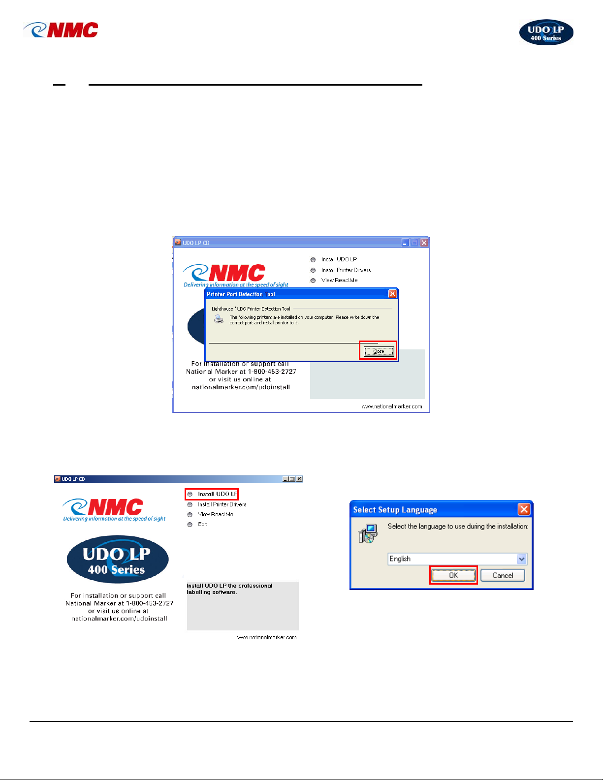
4. A “Printer Port Detection Tool” box will open. This screen will recommend which port
the UDO LP400 Series Printer should use. Write this port down for later use and
click ‘Close’.
5. Click ‘Install UDO LP’. 6. Select the desired language from the drop-down
menu and click ‘OK’.
LP400 User Guide (02/11) v5.2
9
Page 10
UDO LP400 User Guide
_____________________________________________________________________________________________________
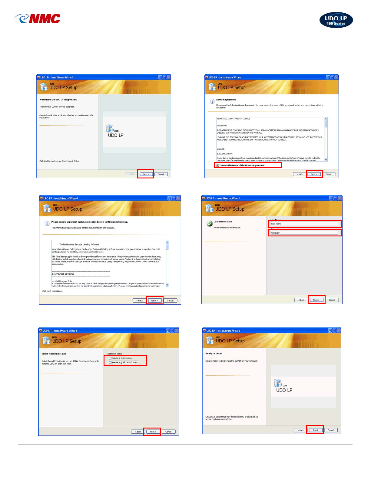
7. Click ‘Next’ and follow the step-by-step Setup
Wizard to install the LP400 Series Software.
(Note: The default options which are set are
those which are recommended.)
9. Review Installation Notes, Click ‘Next’. 10. Enter user name and company; Click, ‘Next’.
8. ‘Click’ accept the terms of the License
Agreement and Click, ‘Next’.
11. If you wish to create a Desktop or Quick Launch
icon, ‘check’ and Click, ‘Next’
LP400 User Guide (02/11) v5.2
10
12. Click, ‘Next’ to begin the installation procedure.
Page 11
UDO LP400 User Guide
_____________________________________________________________________________________________________
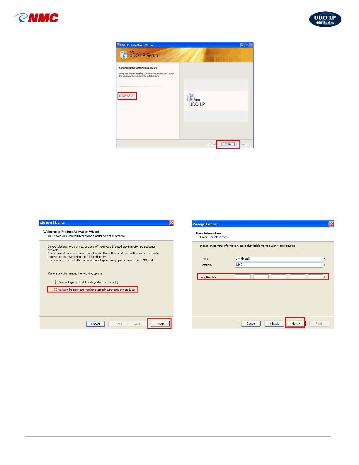
Congratulations! Your UDO LP400 software is now
installed and ready to use. “Check” Run UDO LP and
“Finish” to open your software.
13. To activate your software click ‘Activate the
Package’; click ‘Finish’.
14. Enter your ‘Key Number’ and click ‘Next’.
(Note: To obtain your Key Number call the
UDO Hotline at 1-800-453-2727.)
LP400 User Guide (11/07)
11
Page 12
UDO LP400 User Guide
_____________________________________________________________________________________________________
Set-up Procedure for Printing on Continuous Vinyl
VI.
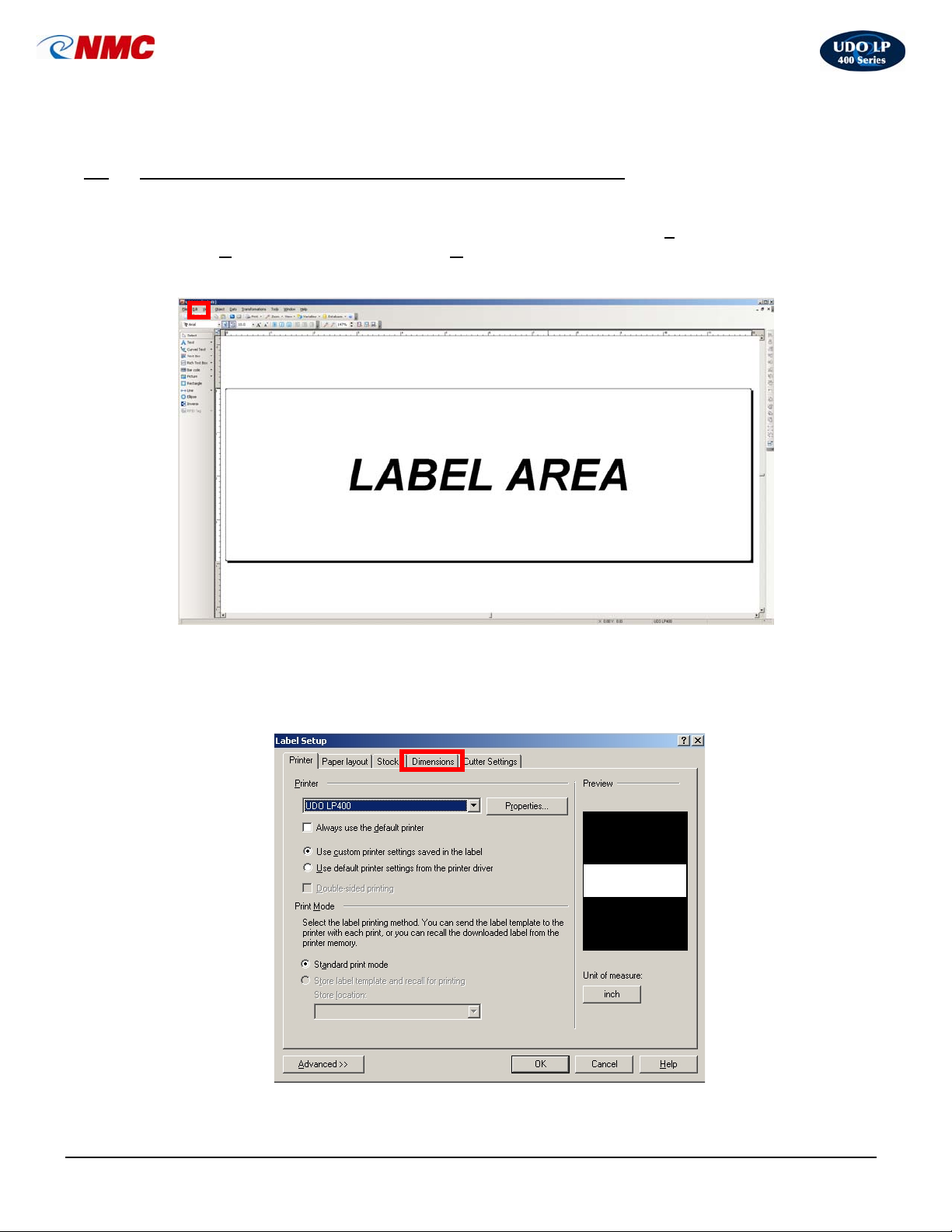
1. To start the UDO LP400 Program – Double-click on the ‘UDO LP400’ desktop icon.
2. To create a new label or retrieve an existing one, Select the ‘F
either ‘N
3. Double-click anywhere in the ‘Label Area’ (Fig. 1).
ew’ to create a new label or ‘Open’ and select the label you wish to retrieve.
ile’ menu; Select
Fig. 1
A. Default Settings & Adjustments
1. Label Dimensions
a. The “Label Setup” Box will open (Fig. 2). Click on the ‘Dimensions’ tab.
Fig. 2
LP400 User Guide (11/07)
12
Page 13
UDO LP400 User Guide
_____________________________________________________________________________________________________
b. “Label Setup” Box (cont.)
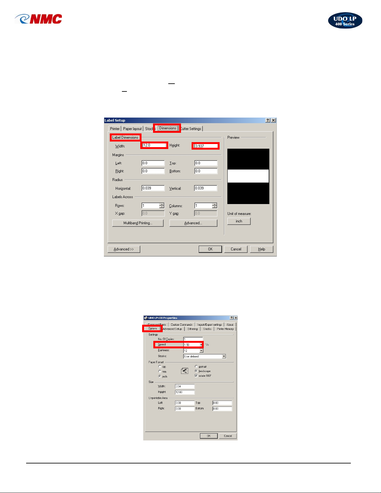
The default settings are set to print on a continuous vinyl label whose
dimensions are H: 3.937” X W: 12” (Fig. 3). The height and width may be
adjusted, as desired. The W
Adjust the H
(Note: The cutter will be activated after the last printed item on your label.)
Click ‘OK’ when you have finished setting desired dimensions.
eight setting accordingly if you are not using a 4” vinyl roll.
idth can be increased to a maximum of 43”.
Fig. 3
2. LP400 Printer Properties
a. Settings. To adjust other default settings Click on the ‘Printer’ tab
(Fig. 2), Click on ‘Properties’, Click on the ‘Options’ tab (Fig. 4). For
example, the Darkness setting may need to be adjusted depending on
the image desired to be printed or the color of print ribbon and vinyl
used (Fig. 4).
Fig. 4
LP400 User Guide (11/07)
13
Page 14
UDO LP400 User Guide
_____________________________________________________________________________________________________
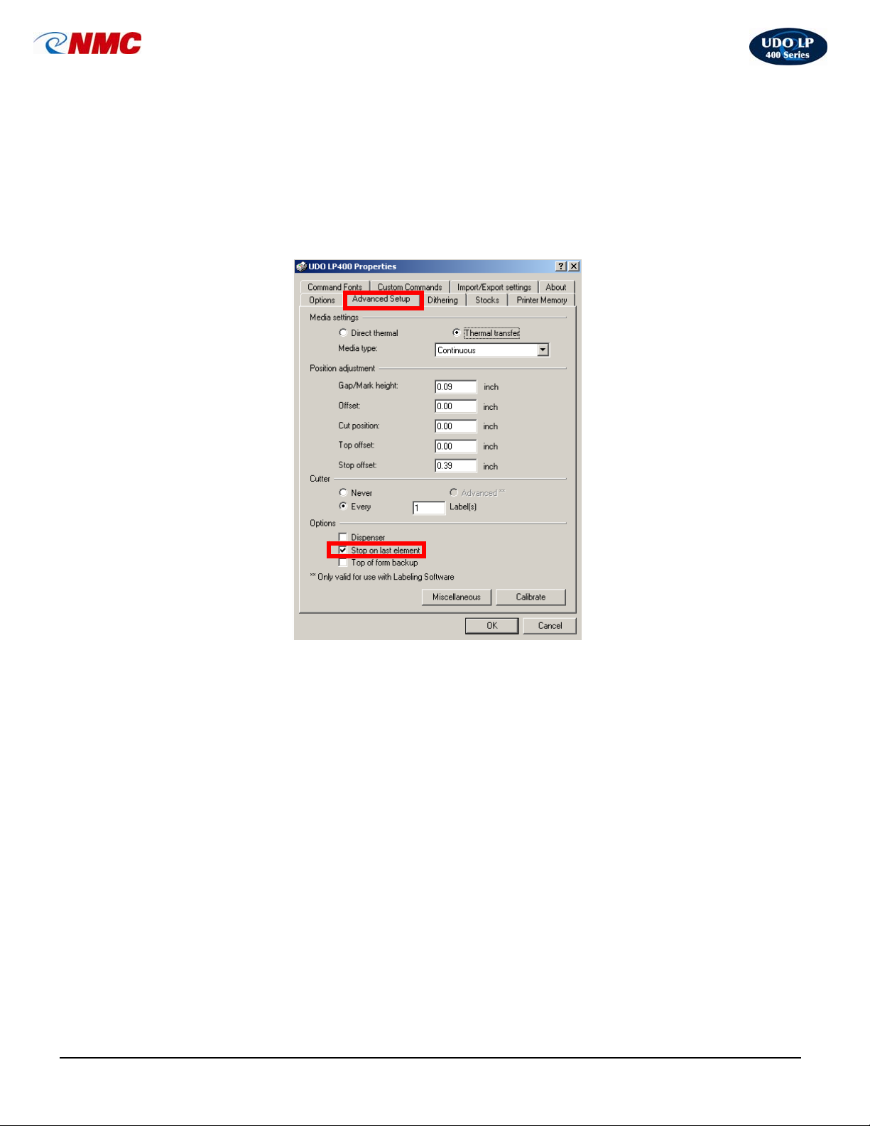
b. Advanced Setup. You may alter the margin between the last
printed element on the label and the point at which the cutter blade is
activated by removing the “checkmark” in the box next to ‘Stop on
last element’. (Note: This is a vinyl saving feature and will effect how
the information on the label is printed.) The other default settings do
not need adjusting for printing continuous vinyl.
Fig. 5
After completing any changes, click ‘OK’ and the Properties Box will close.
Click ‘OK’ in the Label Setup box. You are now ready to design your label!
LP400 User Guide (11/07)
14
Page 15
UDO LP400 User Guide
_____________________________________________________________________________________________________
VII. Navigating the Toolbars
A. The Toolbox Toolbar
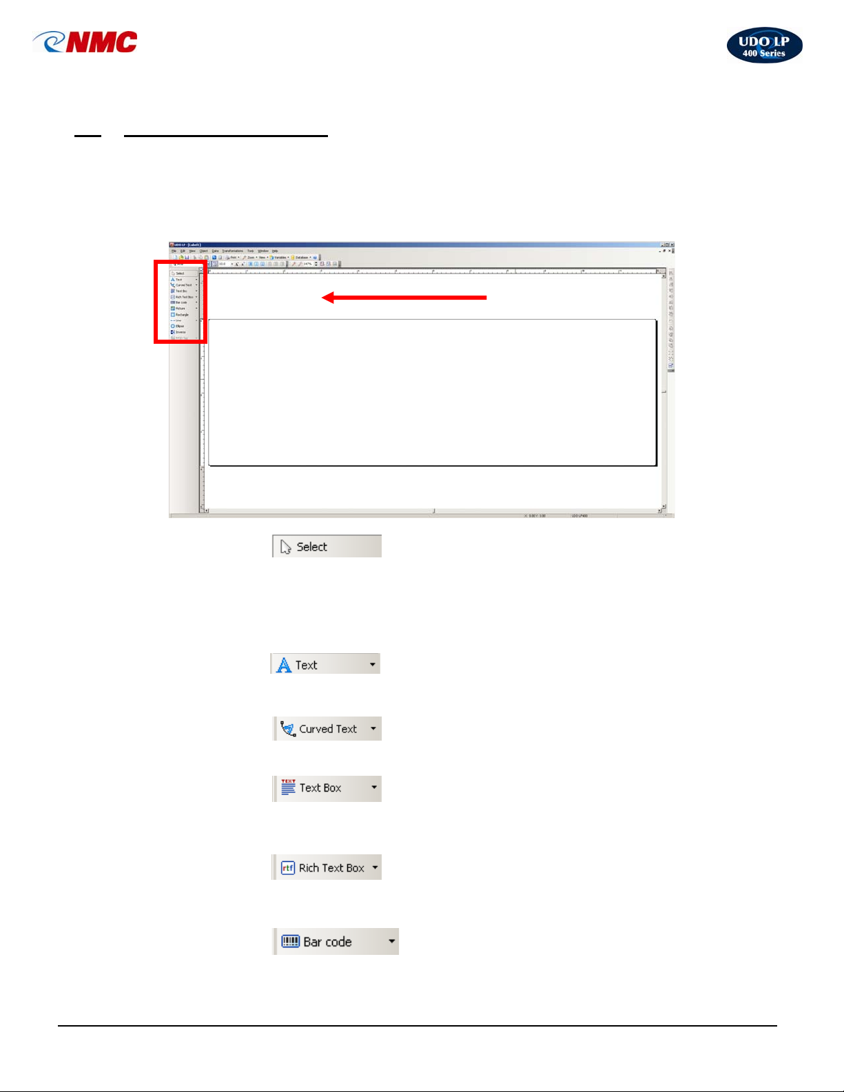
The Toolbox Toolbar contains all frequently used tools to facilitate the design and
printing of labels. Toolbox icons enable you to select elements, invert images, and add
text, pictures, shapes, bar codes, etc.
Toolbox
• Select
The Select tool allows you to manipulate elements. After selecting this tool click the
element to select it. You can select more than one element by holding down the
‘<Shift>’ key while clicking each element. (Note: This tool can also be used to
cancel the selection of elements {i.e. to de-select all previously selected elements}).
• Text
The Text tool allows you to place text strings or single characters on to the label.
• Curved Text
The Curved Text tool allows you to create words or strings of text in a arc
• Text Box
The Text Box tool allows you to insert paragraph text onto the label.
• Rich Text Box
The Rich Text Box tool allows you to utilize fonts in several different sizes, styles and
formatting.
• Bar Code
The Bar Code tool allows you to add bar codes to the label.
LP400 User Guide (11/07)
15
Page 16
UDO LP400 User Guide
_____________________________________________________________________________________________________
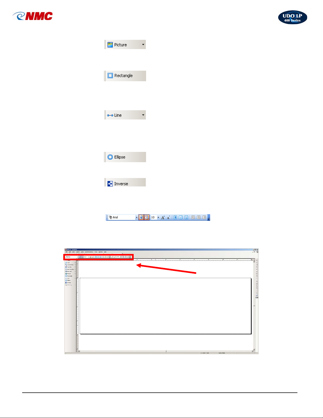
• Picture
The Picture tool allows graphics to be placed on labels. It can be used to add pictures
of products, company logos, etc.
• Rectangle
The Rectangle tool allows you to design and position a rectangle or square. The
upper left corner of the box is set by clicking the desired position; the size of the box is
set by dragging the box to the required size while holding down the mouse button.
• Line
The Line icon allows you to add a horizontal or vertical line to a label. A line can be
drawn by clicking at the desired starting point and dragging the line to its ending point
then releasing the mouse button.
• Ellipse
The Ellipse icon allows to draw ellipses and circles on the label.
• Inverse
Inverse icon creates a rectangle that produces the inverse image of all elements that
are overlapped by it.
B. The Text Toolbar
Use the text toolbar to quickly format the text objects on the label.
Select the text object by clicking it. Click the appropriate shortcut button in the text
toolbar.
Text Toolbar
LP400 User Guide (11/07)
16
Page 17
UDO LP400 User Guide
_____________________________________________________________________________________________________
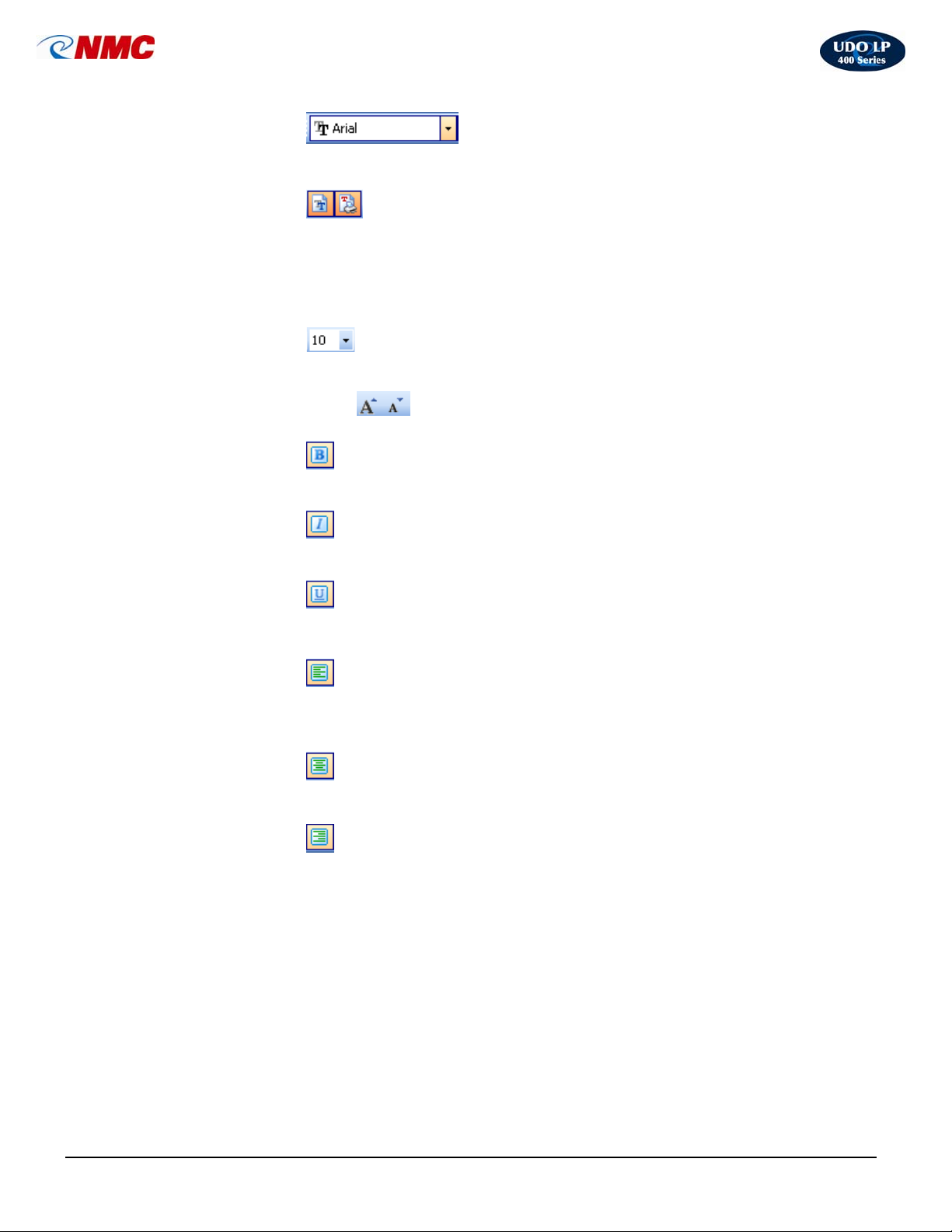
• Font Name
Shows the name of the font in use. Pull down menu allows you to change the font.
• Font Types
Options for fonts installed on your computer and available printer fonts.
Note: You can limit the display of fonts in the list. You can list all fonts on the system,
only graphic fonts (TrueType, opentype, type1, bitmap Windows fonts) or only thermal
printer resident fonts. Click on the two icons next to the list of fonts.
• Font Size
To change the size of the text, click the drop down list and select the appropriate
size. - OR -
You can also click on the
• Bold Type
Formats the selected text in bold style.
• Italic Type
Formats the selected text in italic style.
buttons to enlarge/reduce the size of the font.
• Underline Type
Formats the selected text in underline style.
• Align Left
Aligns text to the left edge.
Note: Alignment buttons are accessible only for multi-line text objects.
• Align Center
Aligns text to the horizontal center.
• Align Right
Aligns text to the right edge.
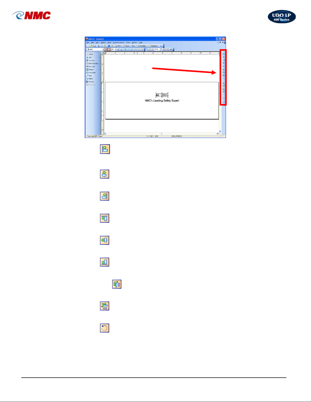
C. The Design / Alignment Toolbar
Click the appropriate buttons in the Design toolbar to align selected objects to each
other.
First you have to select objects that you want to align.
Note: All objects are aligned relatively to the first selected object.
Note: If you hold the ‘<CTRL>’ key while clicking the buttons, objects are aligned
relative to label and not to the first selected object.
LP400 User Guide (11/07)
17
Page 18
UDO LP400 User Guide
_____________________________________________________________________________________________________
Design / Alignment Toolbar
• Left Align
Aligns objects to the left.
• Center Align
Aligns objects to the center.
• Right Align
Aligns objects to the right.
• Top Align
Aligns objects to the top
• Vertical Center
Vertically centers the objects
• Bottom Align
Aligns objects to the bottom
• Horizontal Space
Distributes objects evenly and horizontally, so spacing between them is equal.
• Vertical Space
Distributes objects evenly and vertically, so spacing between them is equal.
• Rotate
The object will be rotated 90° clockwise.
LP400 User Guide (11/07)
18
Page 19
UDO LP400 User Guide
_____________________________________________________________________________________________________
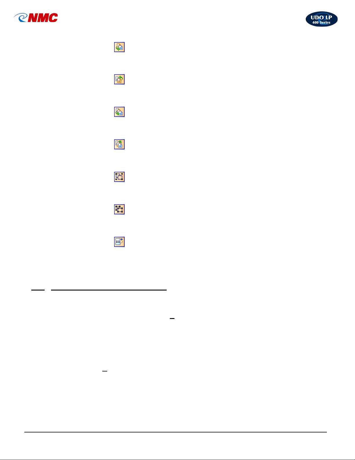
• To Front
Moves object to the top. Use this action to change the order of elements if several
elements overlap each other.
• To Back
Moves object to the back. Use this action to change the order of elements if several
elements overlap each other.
• One to Front
Move selected object to the front by one position. Use this action to change the order
of elements if several elements overlap each other.
• One to Back
Moves object to the back by one position. Use this action to change the order of
elements if several elements overlap each other
• Group
This tool is used to group selected objects into one object. When the objects are
grouped together, you can format them and move them on the label easier.
• Ungroup
This tool is used to ungroup the selected group of objects into the original individual
objects.
• Rotate Label on
Screen
This tool is used to rotate selected objects. Objects are rotated in steps of 90°. Center
of rotation is the center of selected elements
VIII. The Basics of Designing a Label
.
A. Inserting an Image
This section will take you through the basic steps of how to insert an image onto a label.
For more in-depth information, click the ‘H
elp’ menu at the top of the screen or contact
NMC.
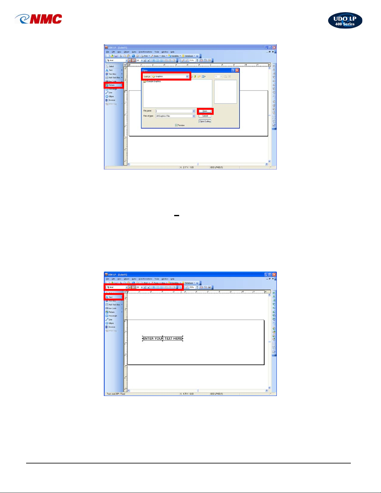
1. Click on the ‘Picture’ button (Fig. 1) in the toolbox toolbar to the left of the
screen. Move the cursor to the correct position on the label field then click. A
dialog box will open.
2. Locate the image file on your computer or disk; select by clicking on the file.
Click ‘O
LP400 User Guide (11/07)
pen’.
19
Page 20
UDO LP400 User Guide
_____________________________________________________________________________________________________
Fig. 1
B. Inserting Text
This section will take you through the basic steps of how to insert text onto a label. For
more in-depth information, click the ‘H
elp’ menu at the top of the screen or contact
NMC.
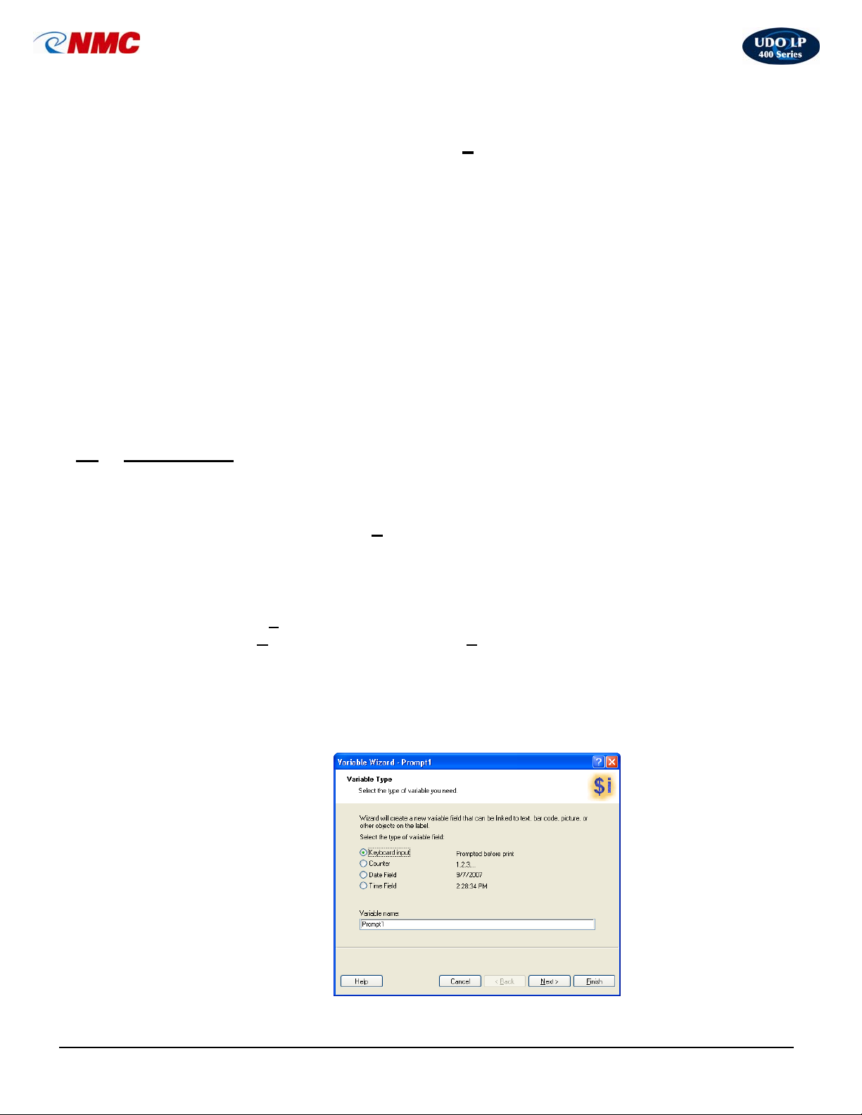
1. Click on the ‘Text’ button (Fig. 2) located on the toolbox toolbar to the left of
the screen (Note: The A will appear next to the cursor.) Move the cursor to
the correct position on the label field then click. A dialog box will open.
2. Type your message (Fig. 2). As you type a text box will appear. Adjust the
text appearance from the ‘Text Toolbar’ (Fig. 2).
Fig. 2
LP400 User Guide (11/07)
20
Page 21
UDO LP400 User Guide
_____________________________________________________________________________________________________
C. Resizing & Positioning Objects
This section will take you through the basic steps of resizing and positioning an object in
a label. For more in-depth information, click the ‘H
contact NMC.
To resize a symbol
1. Select the object – The selected object is framed with a rectangle.
2. Click on one of the small rectangles in the corners of the rectangle.
3. Hold the mouse key pressed.
4. Move the position of the cursor on the screen. The object will resize with the
cursor.
elp’ menu at the top of the screen or
To position a symbol
1. Select the object
2. Click on the object.
3. Hold the mouse key pressed.
4. Move the position of the cursor on the screen. The object will move with the
cursor.
IX. Applications
A. Setting-Up Variables
This section will take you through the basic steps of how to add a variable to a label. For
more in-depth information, click the H
The variable wizard simplifies and speeds up the creation of the most common types of
variables.
1. Click on ‘Tools’ in the file menu.
2. Select ‘U
3. Click the box beside ‘Variable Wizard’ to select this option. Click ‘OK’.
4. Activate the Variable Wizard by Clicking the ‘Variables’ button from the
menu at the top of the screen. (Fig. 1)
5. Type in the variable name and select the type of variable. (Fig. 1)
6. Follow the step-by-step wizard instructions in figures 8 – 10.
ser Interface’ and click the ‘Settings’ option from the menu.
elp menu at the top of the screen or contact NMC.
Fig. 1
LP400 User Guide (11/07)
21
Page 22
UDO LP400 User Guide
_____________________________________________________________________________________________________
Fig. 2
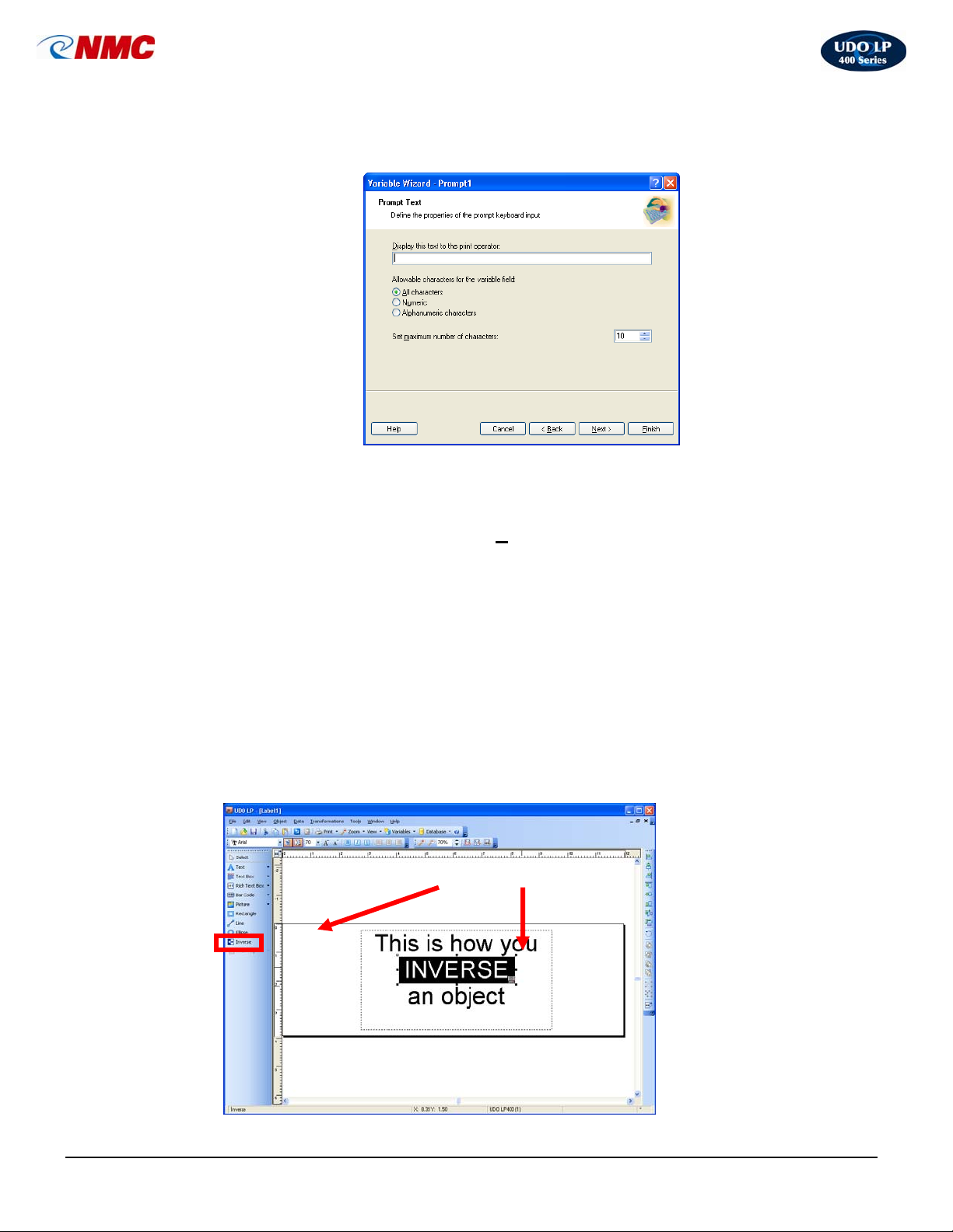
B. Inversing (Reverse Print)
This section will take you through the basic steps of how to add an inverse object to a
label. For more in-depth information, click the ‘H
elp’ menu at the top of the screen or
contact NMC.
The Inverse tool creates a rectangle that produces the inverse image of all elements
within the box.
1. Click on the ‘Inverse’ button in the Toolbox (Fig. 4).
2. Define the starting point by clicking the mouse at the upper-left of the object
(start position).
3. Drag the cursor to the end point. An inverse rectangle will be drawn from the
left to the right side of the label.
4. You can change the size and position of the inverted box by dragging it over
the label.
Fig. 4
5.
LP400 User Guide (11/07)
Inverse Inverse Box
22
Page 23
UDO LP400 User Guide
_____________________________________________________________________________________________________
C. Rotating Text & Symbols
This section will take you through the basic steps of how to rotate an object on a label.
For more in-depth information, click the ‘H
elp’ menu at the top of the screen or contact
NMC.
a. Select the object.
b. Click on the ‘Rotate’ icon in the Design/Alignment Toolbar to the right of
the screen. The object will be rotated 90° clockwise.
NOTE: This option can also be selected though the ‘T
ransformations’ menu ‘Rotate’.
If the Design/Alignment Toolbar is not visible, click the ‘View’ menu then select
‘Toolbars’. Click on ‘Design’.
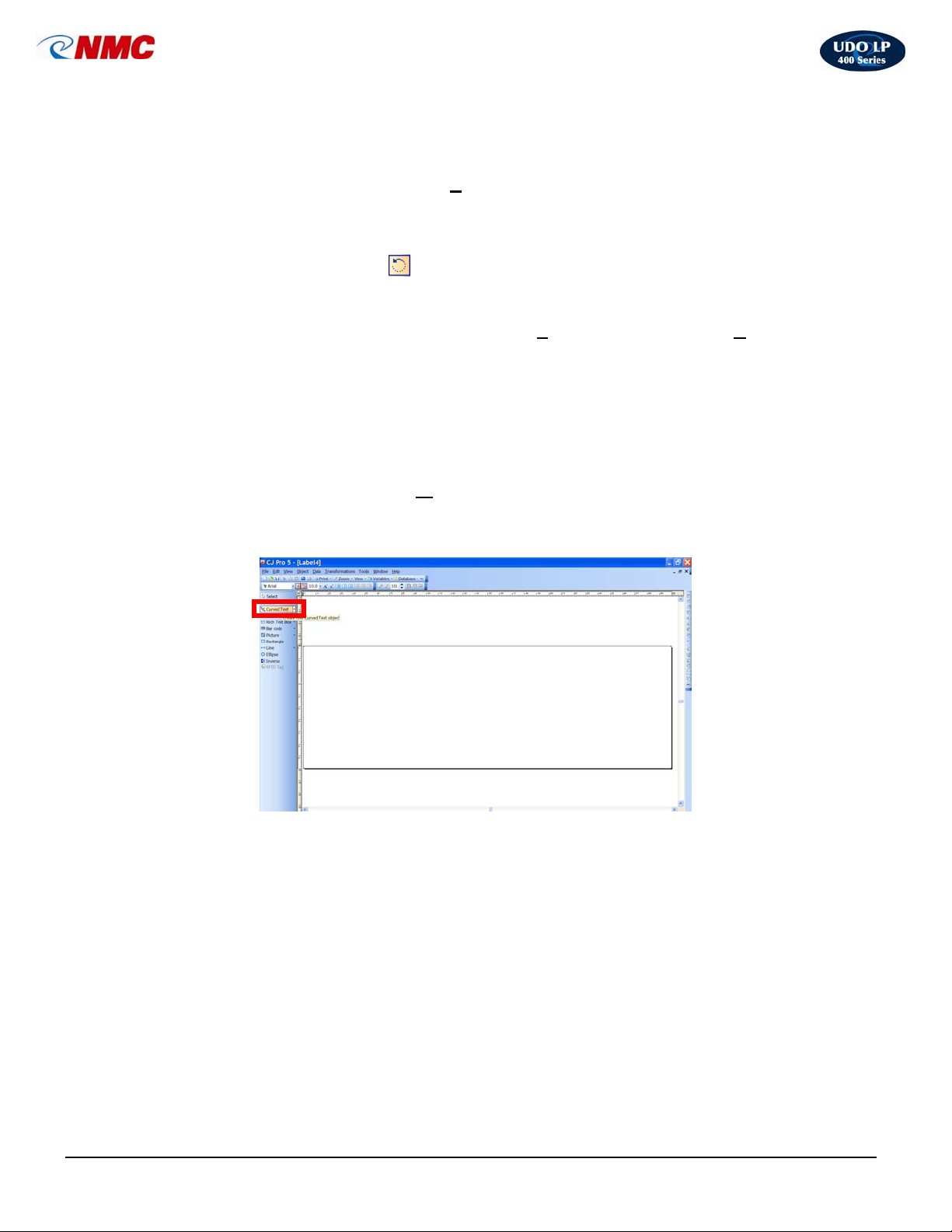
D. Curved Text
This section will take you through the basic steps of how to produce curved text. For
more in-depth information, click the ‘H
NMC.
1. Click on Curved Text then click on the label (Fig. 5)
elp’ menu at the top of the screen or contact
Fig. 5
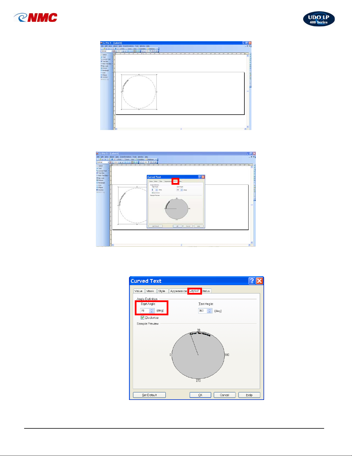
2. Insert the required text and click on OK. Increase the font size
accordingly. The text will appear in a small circle. Hold the
SHIFT key down while stretching the text out – this keeps the
text in proportion. (Fig. 6)
LP400 User Guide (11/07)
23
Page 24
UDO LP400 User Guide
_____________________________________________________________________________________________________
Fig. 6
3. Double click on the text and go to the Layout tab (Fig. 7)
Fig. 7
4. Increase the Start Angle so that the text is at the top of the
screen (Fig. 8)
Fig. 8
LP400 User Guide (11/07)
24
Page 25
UDO LP400 User Guide
_____________________________________________________________________________________________________
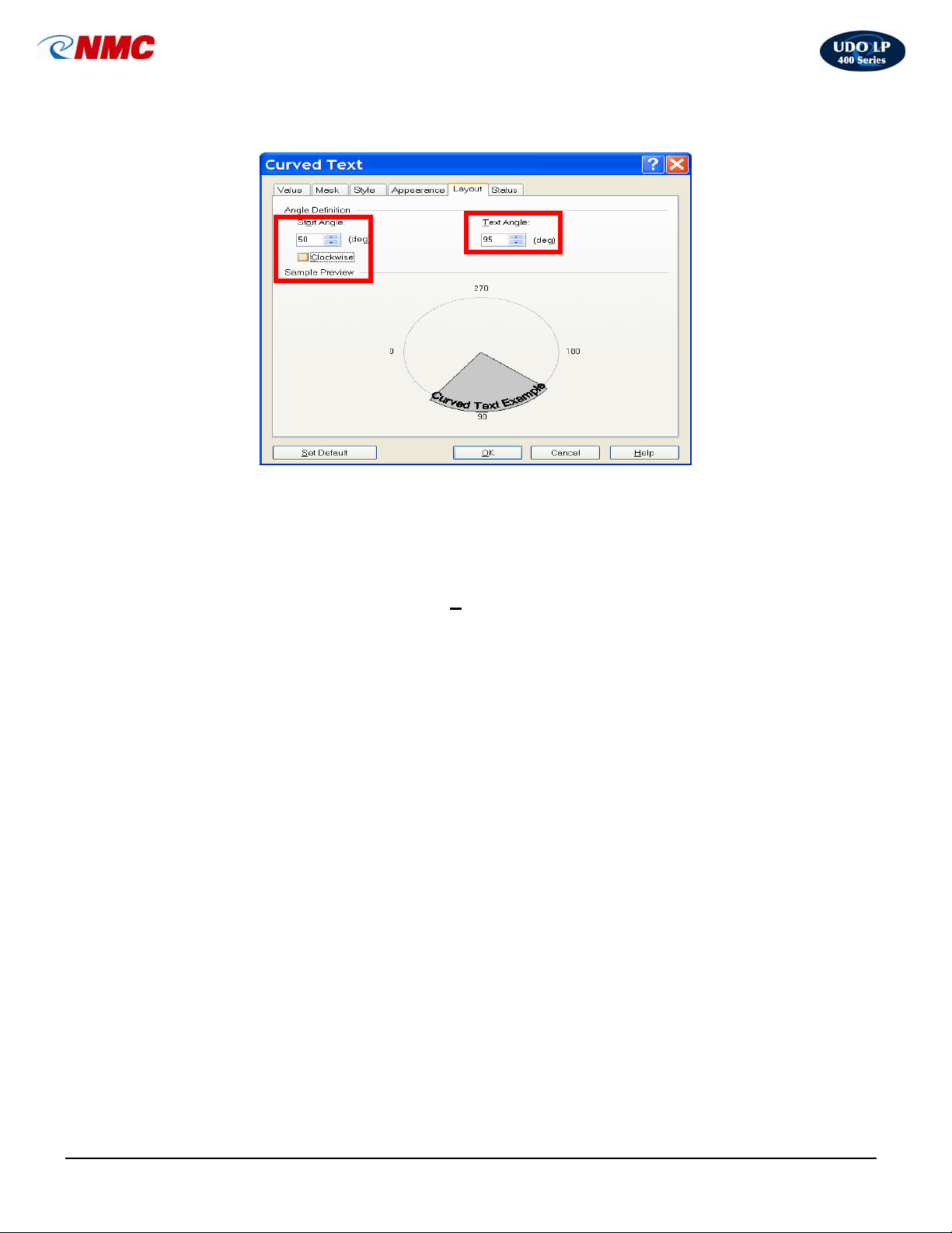
5. Reduce the Text Angle to cover just the actual required text
E. Importing Pictures
This section will take you through the basic steps of how to import a picture to a label.
For more in-depth information, click the ‘H
NMC.
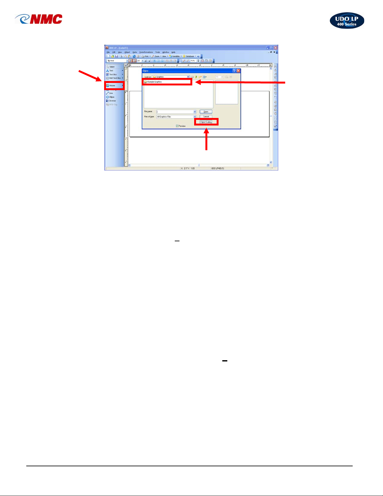
1. Click on the ‘Picture’ tool in the Toolbox (Fig. 5).
2. Click on the label, where you want to place the picture. The ‘Open’ dialog
box appears.
3. Browse for the picture on the hard drive then Click the ‘Open’ button (Fig. 5)
- OR -
Select pictures from the Clipart Gallery by Clicking on the button ‘ClipArt
Gallery’ (Fig. 5).
4. Choose the picture from the gallery; Click the ‘OK’ button.
elp’ menu at the top of the screen or contact
LP400 User Guide (11/07)
25
Page 26
UDO LP400 User Guide
p
y
_____________________________________________________________________________________________________
Picture object
in toolbox
Locate/Open Picture on
hard drive
en Clipart Galler
Fig. 5
O
Images can be various sizes. If the original size of the graphic is not valid for the size of
the label, you can resize the image by dragging the handles surrounding it. The image
can be resized proportionally or stretched in both directions.
The graphic objects can also be placed on the label from the clipboard or imported from
another applications (i.e. Corel Draw, scanning programs, etc.) using either the ‘Insert
Object’ or ‘Paste’ command from the ‘E
dit’ menu. By using this method the graphic is
embedded in the label file. This means it is entirely stored in the label file and is not
stored separately on the hard disk. However, graphics imported this way can be saved
to the file at any time.
When you define graphics as a variable object (some variables define the name of the
picture), Label Designer does not know the size of the picture in advance. This
information is provided only at the time of print or preview. There will be a picture-box on
the screen containing a large question mark when this occurs.
F. Multi-band Printing: Creating Large Signs & Labels
This section will take you through the basic steps of how to create a multi-band or tiled
label or sign. For more in-depth information, click the ‘H
elp’ menu at the top of the
screen or contact NMC.
The Multi-band printing option allows you to print larger labels and signs than the
maximum width supported on your printer. The label bands can then be joined together
to form one large label or sign. The UDO LP400 Series Software is capable of printing
from 2 to 5 vinyl strips of 4” widths; enabling you to produce signs up to 20” in height.
For example, if your printer has 4" wide print head, you can normally print only 4" wide
labels. But with enabled multi-band printing you can print two bands of labels. When you
join them the result will be 8" wide label.
LP400 User Guide (11/07)
26
Page 27
UDO LP400 User Guide
_____________________________________________________________________________________________________
When you enable the multi-band option, some options in the dialog box will become
unavailable as multi-band printing overrides them.
The dimensions of the label are entered in millimeters (mm), centimeters (cm), inches
(inch) or dots (dot) according to your previous selection. You can change the unit that
dimensions are displayed in by clicking the ‘Unit’ button below the label preview in
‘Label Setup’ (Click ‘F
ile’ from the menu bar, select ‘Label Setup’ then click on the
‘Printer’ tab).
1. Open the ‘L
and choose ‘L
abel Setup’ dialogue box by either right clicking on the label
abel Setup’ or choose ‘File’ then choose ‘Label Setup’ from
the top menu.
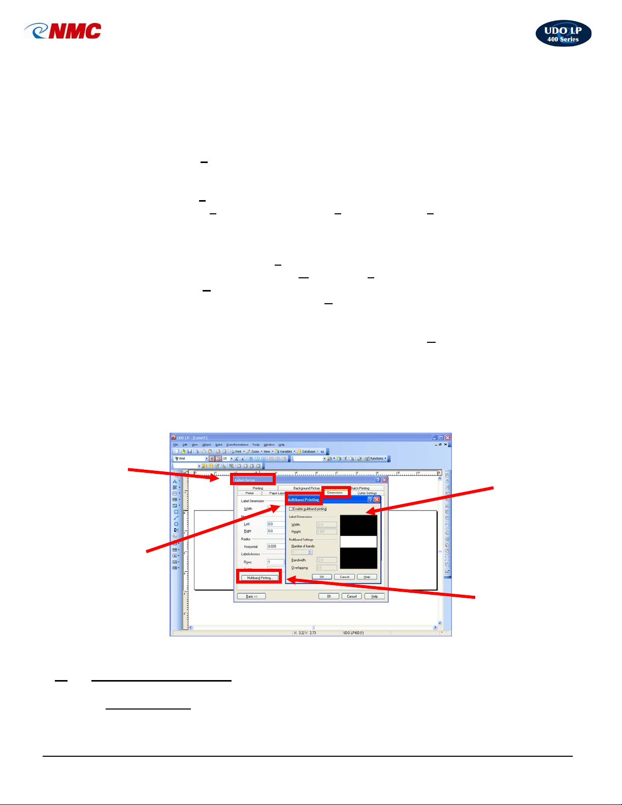
2. Click on the ‘Dimensions’ tab (Fig. 6).
3. Click on ‘Multi-band Printing’ button (Fig. 6).
4. Check ‘Enable Multi-band
5. Define the label dimensions – ‘W
6. Define the ‘N
umber of bands’ (strips) you want to use (Fig. 6).
7. Enter the width of each band in the ‘B
Printing’ (Fig. 6).
idth’ and ‘Height’ (Fig. 6).
andwidth’ field. The printing on each
band will be as wide as specified by this field. The maximum height of the
band is the height of the print head (4”).
8. Enter the amount of space on the label to overlap in the ‘O
verlapping’ field.
This field specifies the amount of space on the label which overlaps with the
neighboring label. Label bands can be easier joined together, if they overlap
(Fig. 6). NOTE: Look at the label preview to see how your settings affect the
label layout.
9. Click ‘OK’ in the Multi-band Printing dialogue box (Fig. 6).
10. Click ‘OK’ in the Label Setup dialogue box (Fig. 6).
Label Setup
Dialogue
Box
Multiband
Printing
Dialogue
Box
Fig. 6
Common Applications
X.
A. Directional Sign
Dimensions Tab
Multiband
Printing…
LP400 User Guide (11/07)
27
Page 28
UDO LP400 User Guide
_____________________________________________________________________________________________________
section will take you through the steps of how to design and print a directional label. For
more in-depth information, click the ‘H
elp’ menu at the top of the screen or contact
NMC.
Designing this label will require you to incorporate both text and a symbol from the builtin clipart gallery into the label.
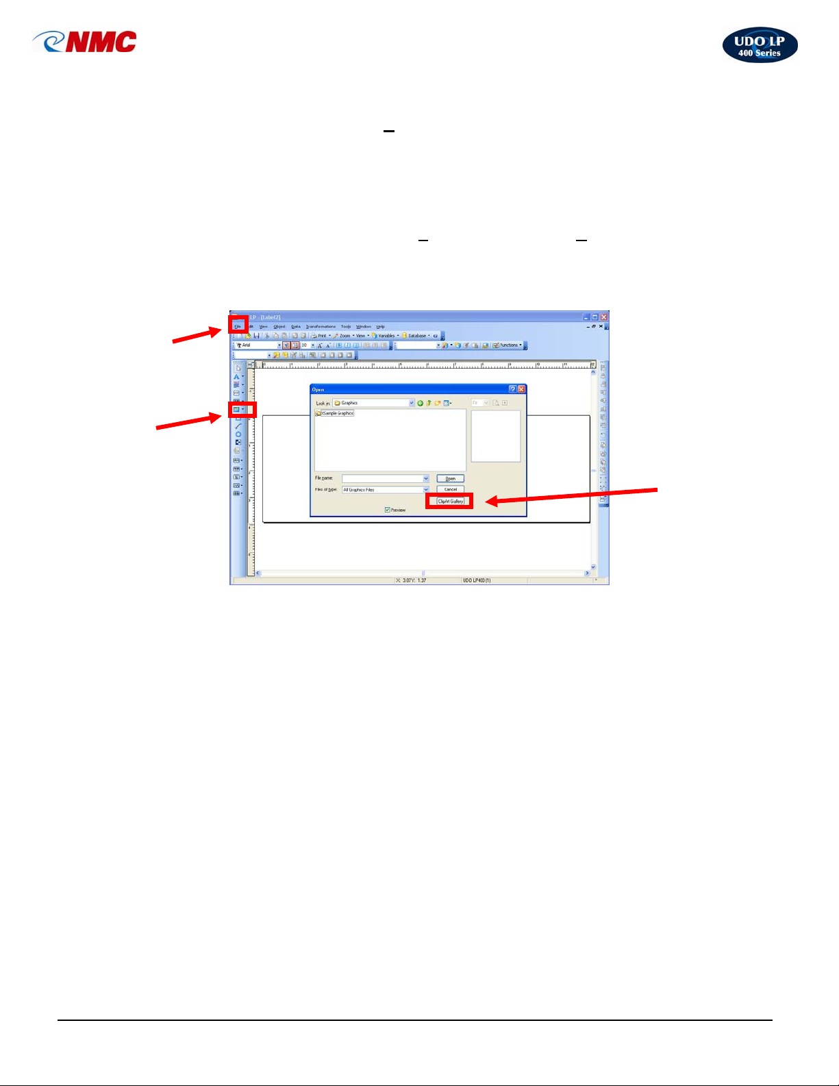
1. To create a new label, open the ‘F
ile’ menu and select ‘New’ or Click on the
‘Create new label’ icon.
2. Click on the ‘Picture’ button (Fig. 1) located on the toolbar to the left of your
screen. Click the cursor in the label field where you want the image located.
File Menu
Picture Tab
Fig. 1
3. Click on ‘Clipart Gallery’ (Fig. 2)
The Clipart Gallery is split into three sections:
-Symbols for EU
-Symbols for UK
-Symbols for USA
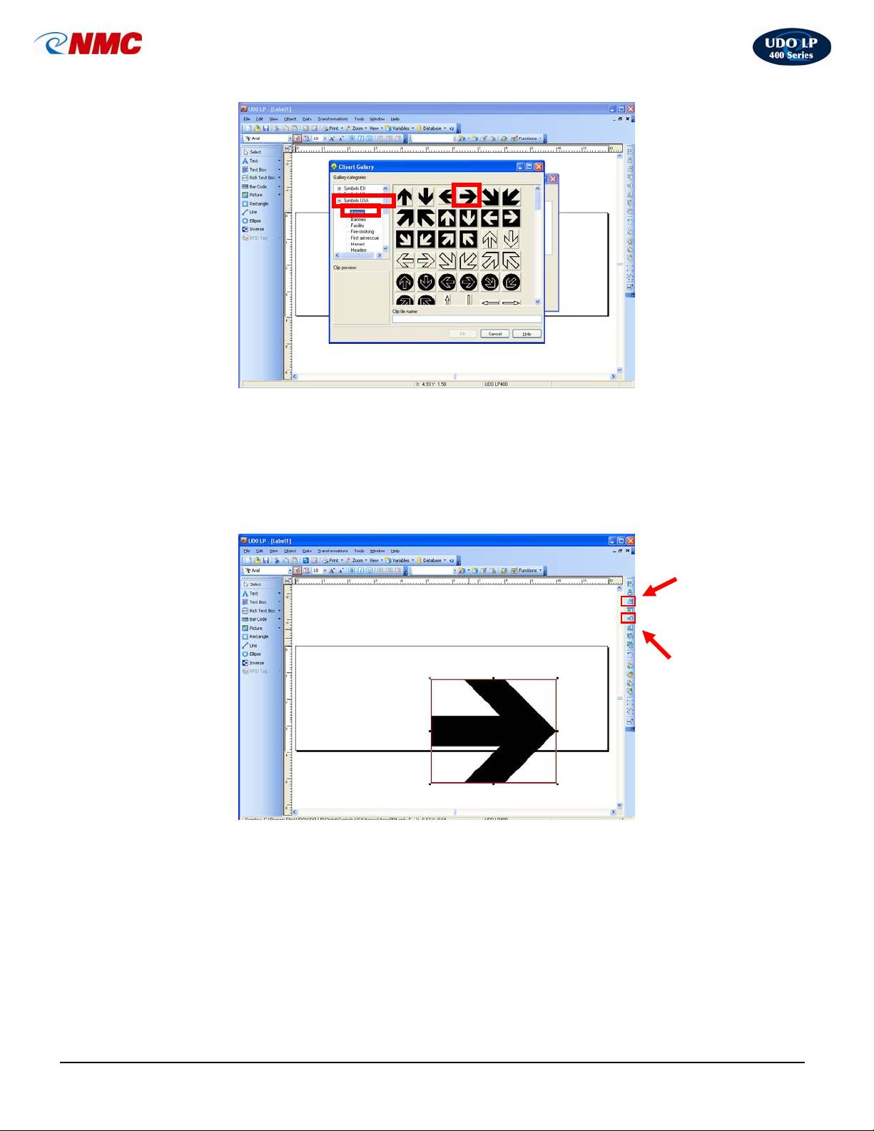
To view the various safety categories listed within each section, click on the
‘+’ symbol next to each of the sections.
4. Click on the ‘+’
next to ‘Symbols USA’. Click on the ‘Arrows’ category,
Double-Click on the arrow symbol shown (Fig. 2) or select the symbol and
Click ‘OK’.
Clipart
Gallery
LP400 User Guide (11/07)
28
Page 29
UDO LP400 User Guide
_____________________________________________________________________________________________________
Fig. 2
5. The label should now appear as in Figure 3. Hold down the ‘Ctrl’ button and
Click on the ‘right alignment’ tool from the Design/Alignment Toolbar. Hold
down the ‘Ctrl’ button and Click on the ‘Vertical Center Alignment’ tool
from the Design/Alignment Toolbar. (Note: If any portion of the image is
outside of the label area the box outline will turn red. Anything outside of the
label area will not appear on the label.)
Fig. 3
After aligning the image on the label it should appear as in Fig. 4.
Right
Alignment
Icon
Vertical
Center
Alignment
Icon
LP400 User Guide (11/07)
29
Page 30
UDO LP400 User Guide
_____________________________________________________________________________________________________
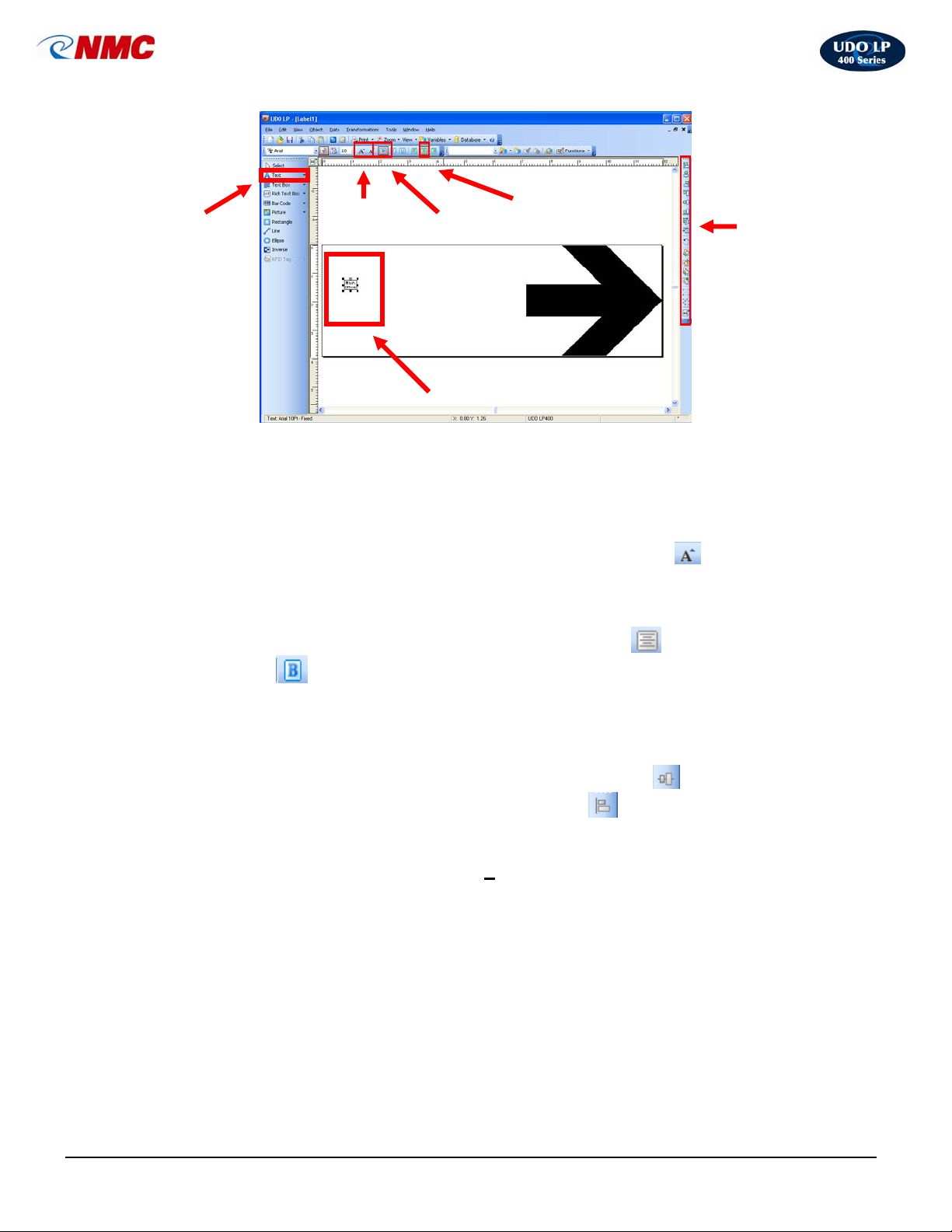
Text
Fig. 4
Increase
Font Size
Bold Text
Selected
Text Box
Center
Align Text
Design /
Alignment
Toolbar
6. Select the ‘Text’ tool (Fig. 4) from the toolbox toolbar located on the left side
of the screen. Position the cursor on the label and click. (Note: The ‘A’ will
appear next to the cursor.) Type in the text “Main Office” on two lines. Click
the text box or the label to select the text box (Fig. 4).
7. With the Text Box selected, Click the ‘Increase Font Size’
text toolbar (Fig. 4). You may also change the font size from the pull down
menu or type in the size. Increase the font size to 104.
8. With the Text Box selected, Click the ‘Center’ button
icon from the
icon. Click the
‘Bold’
icon (Fig. 4) (just as you would if you were using MS Word) from
the Text Toolbar at the top of the screen (Fig. 4).
9. With the Text Box selected, hold down the ‘Ctrl’ button and align the text
box to the label using the Design/Alignment toolbar on the right side of the
screen (Fig. 4). Click on the icons to ‘Vertically Center’
‘Left Align’ the text box to the edge of the label
(Fig. 4).
the text box and
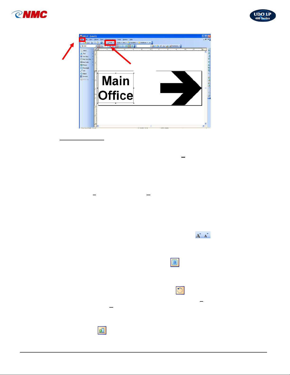
10. The label should look like the label in Fig. 5. The label is now ready to print.
Click on the ‘Print’ icon or select ‘F
ile’ from the top menu, and then choose
‘Print’.
LP400 User Guide (11/07)
30
Page 31
UDO LP400 User Guide
_____________________________________________________________________________________________________
File
Menu
Fig. 5
Print
Icon
B. Pipe Marker Label
This section will take you through the steps of how to design and print a directional
pipemarker label. For more in-depth information, click the ‘H
elp’ menu at the top of the
screen or contact NMC.
Designing this label will require you to incorporate both text and a symbol from the builtin clipart gallery into your label.
1. Open the ‘F
ile’ menu and select ‘New’ to create a new label.
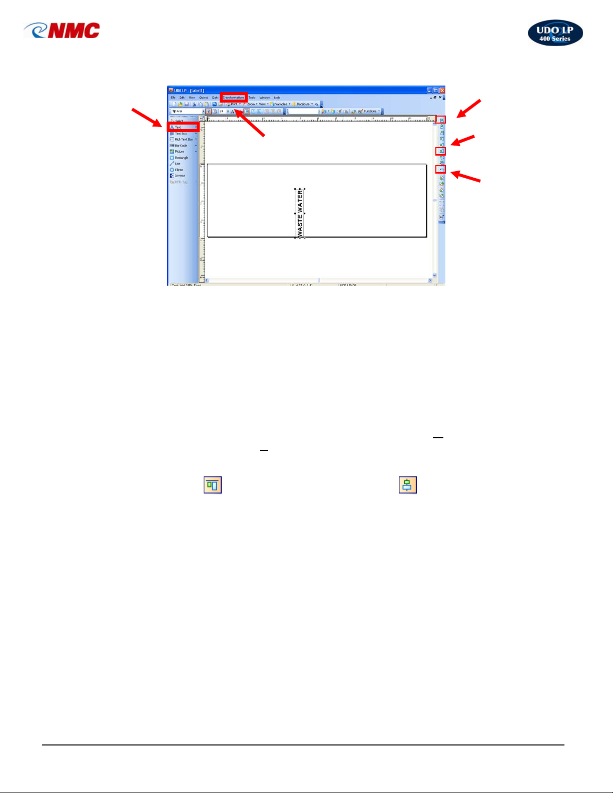
2. Select the Text tool (Fig. 6). Position the cursor on the label and click.
(Note: The ‘A’ will appear next to the cursor.) Type, in all caps, the text
WASTE WATER on one line. Click on the text box or on the label to select
the text box.
3. With the Text Box selected, Click ‘Increase Font Size’
text toolbar (Fig. 6), select from the pull down menu or type in the size.
Increase the font size to 24.
4. With the Text Box selected, click the ‘Bold’ icon (Fig. 4), (just as you
would if you were using MS Word) from the Text Toolbar at the top of the
screen (Fig. 4).
5. With the Text Box selected, Click the ‘Rotate’ icon from the
Design/Alignment Tool Bar or select this option from the ‘T
menu and select ‘R
counter clockwise (Fig. 6).
6. With the Text Box selected, hold down the ‘Ctrl’ button and Click ‘Bottom
Alignment’
LP400 User Guide (11/07)
icon from the
ransformations’
otate’ from the top menu. The Text Box will rotate 90°
icon from the Design / Alignment Tool Bar.
31
Page 32
UDO LP400 User Guide
_____________________________________________________________________________________________________
Text
Option
Transformations
Menu
Left
Alignment
Bottom
Alignment
Rotate
Object
Fig. 6
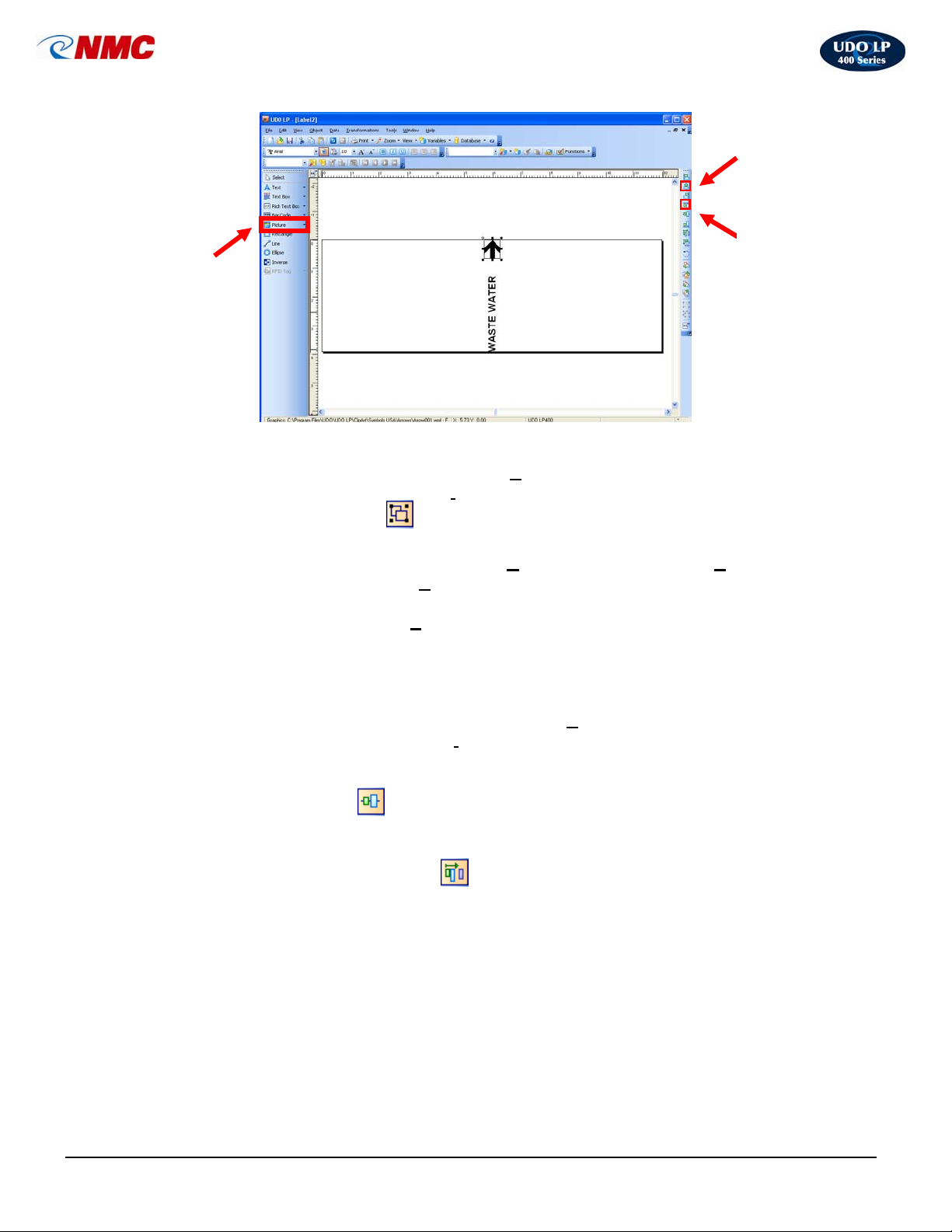
7. Select the ‘Picture’ tool (Fig. 7 located on the toolbar to the left of your
screen. Click the cursor in the label field where you want the image located.
8. Click on Clipart Gallery (Fig. 2)
9. Select the ‘+’
Click on the top left arrow symbol shown or select the symbol (top left
arrow).Click ‘OK’.
10. Right Click on the arrow image and Select the Properties option. Click the
‘Appearance’ tab from the Graphics Window. Change the ‘W
inches and change the ‘H
11. With the Picture selected, hold down the ‘Ctrl’ button and Click ‘Top
to ‘Symbols USA’. Click on the Arrows category; Double-
next
idth’ to .549
eight’ to .658. Click ‘OK’.
Alignment’
Design/Alignment Tool Bar. The label should appear as in Figure 7.
LP400 User Guide (11/07)
icon. Click the ‘Center Alignment’ from the
32
Page 33
UDO LP400 User Guide
_____________________________________________________________________________________________________
Center
Alignment
Insert
Picture
Fig. 7
Top
Alignment
12. Click ‘Select’ in the Toolbox on the left. Click and Drag over the objects to
select them both. You can also click ‘E
Select and choose ‘Select Al
13. Click on the ‘Group’
l’ or ‘Ctrl + A’.
icon from the Design/Alignment Tool Bar (Fig. 8).
14. Right Click on the object and select ‘C
the top menu and select ‘C
15. Right Click then select ‘P
opy’ or ‘Ctrl + C’.
aste’. Repeat this step eleven times (11x), spacing
dit’ from the top menu then click
opy’. You can also click ‘Edit’ from
the objects out across the label. Do not be concerned with exact positioning.
You should have a total of twelve objects across the label.
16. Click ‘Select’ in the Toolbox on the left. Click and Drag over all the objects
to select them. Alternatively, you can Select ‘E
‘Select’ and choose ‘Select Al
l’ or press ‘Ctrl + A’.
dit’ from the top menu, click
17. With all the objects selected, hold down the ‘Ctrl’ button and Click the
‘Vertical Center’
18. With all the objects selected, hold down the ‘Ctrl’ button and Click the
‘Horizontal Space Equally’
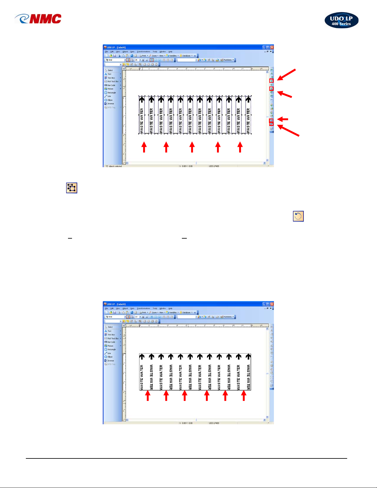
The label should appear as in Figure 8.
LP400 User Guide (11/07)
icon from the Design/Alignment Tool Bar (Fig. 8).
icon from the Design/Alignment Tool Bar.
33
Page 34
UDO LP400 User Guide
_____________________________________________________________________________________________________
Vertical
Center
Horizonal Space
Equally
Group
Ungroup
Fig. 8
Rotate 180°
19. With all the objects selected, hold down the ‘Ctrl’ button and Click the ‘Ungroup’
icon from the Design/Alignment Tool Bar. Click on the outside of the label to
unselect all of the objects.
20. Click the second Text Box from the left side of the label. Click the ‘Rotate’
icon
from the Design/Alignment Tool Bar. You can also select this option from the
‘T
ransformations’ menu then select ‘Rotate’. The Text Box will rotate 90° counter
clockwise. Rotate the text box 180° (two clicks).
21. Repeat step 21 for every other Text Box as indicated in Figure 8. The label should
appear as in Figure 9.
22. The label is now ready to print. Save the file.
Fig. 9
LP400 User Guide (11/07)
Rotated Text
34
Page 35
UDO LP400 User Guide
_____________________________________________________________________________________________________
C. Inverted Text
This section will take you through the steps of how to design a label using the Inverse
feature. For more in-depth information, click the ‘H
elp’ menu at the top of the screen or
contact NMC.
1. Open the ‘F
ile’ menu and select ‘New’ to create a new label.
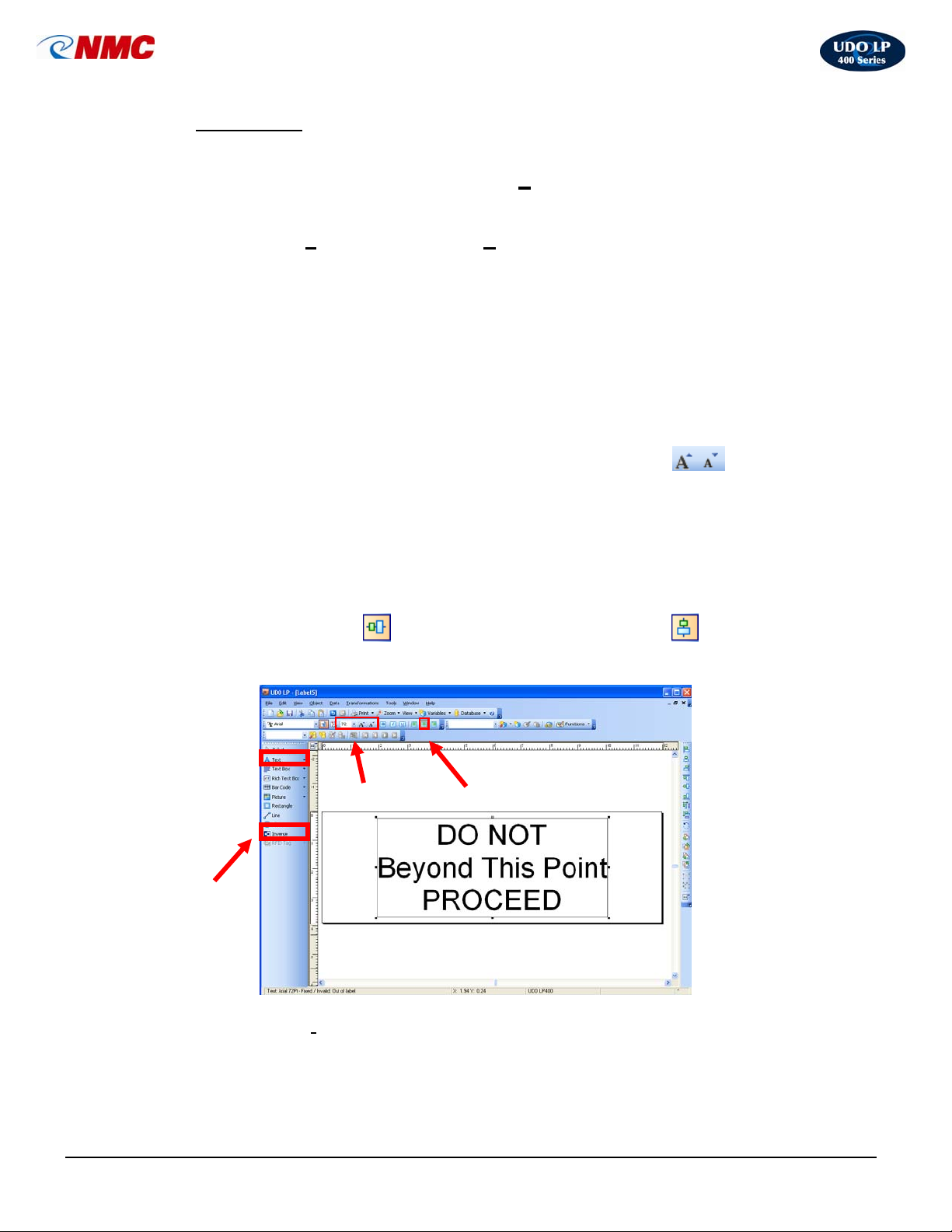
2. Select the Text tool (Fig. 10). Position the cursor on the label and click.
(Note: The ‘A’ will appear next to the cursor.) Type the text on three lines:
DO NOT
Beyond This Point
PROCEED
Now click on the text box or on the label to select the text box.
3. With the Text Box selected, click the ‘Increase Font Size’ icon from
the text toolbar (Fig. 10). You can also change the font size from the pull
down menu or type in the size. Increase the font size to 72.
4. With the Text Box selected, click the ‘Center Alignment’ option from the
Text Menu (Fig. 10).
5. With the text box selected, hold down the ‘Ctrl’ button and Click the
Fig. 10
‘Vertical Center’
Design/Alignment Tool Bar (Fig. 10). The label should look like Figure 10.
Inverse
6. Select the ‘I
extending the Inverse Box from left to right over the top line (Fig. 11).
icon. Click the ‘Center Alignment’ icon from the
Font Size
Center
nverse’ option from the Toolbox. Click and Drag on the label
LP400 User Guide (11/07)
35
Page 36
UDO LP400 User Guide
_____________________________________________________________________________________________________
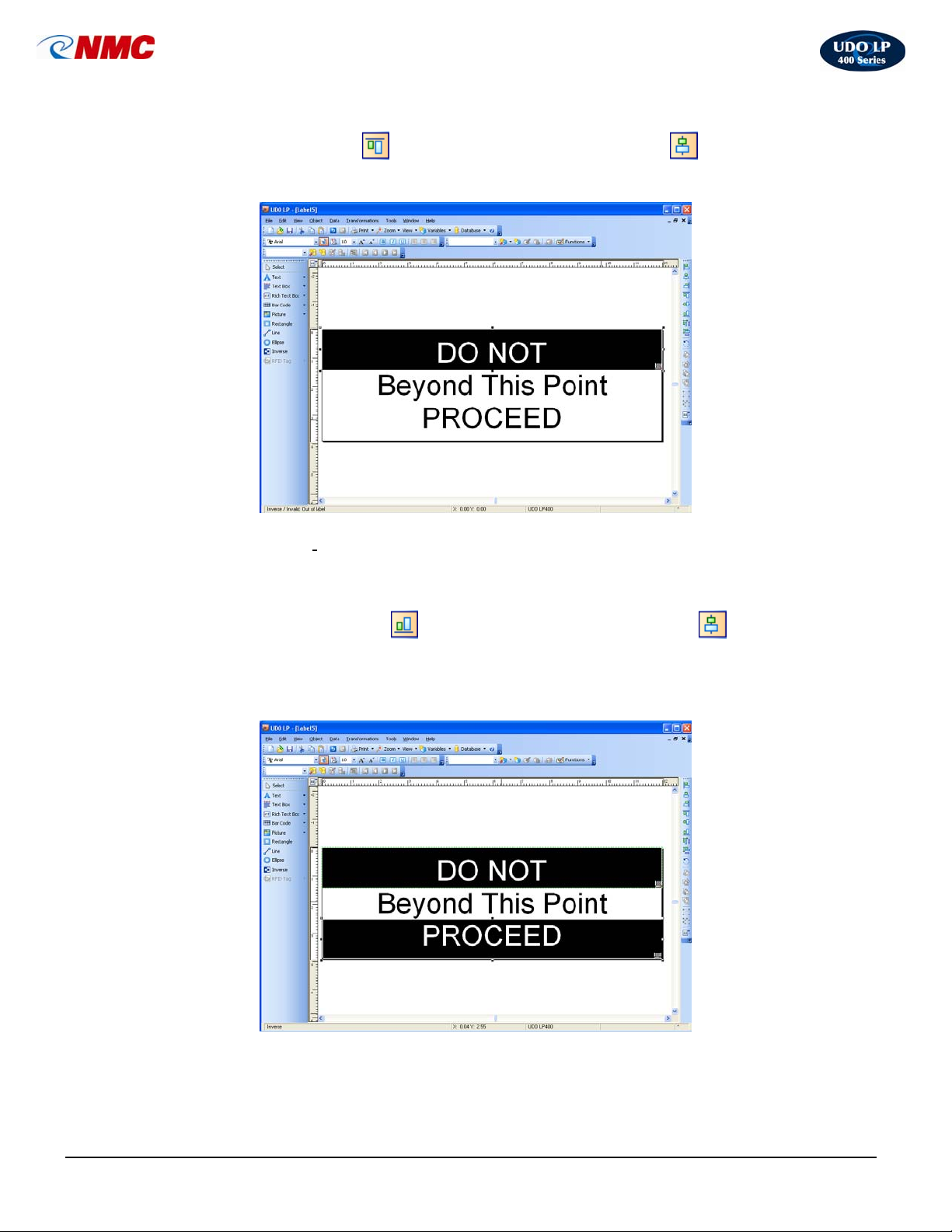
7. With the Inverse Box selected, hold down the ‘Ctrl’ button and Click the
Fig. 11
‘Top Alignment’
icon. Click the ‘Center Alignment’ icon from the
Design/Alignment Tool Bar. The label should appear as in Figure 11.
8. Select the ‘I
nverse’ option from the Toolbox. Click and Drag on the label
extending the Inverse Box from left to right over the bottom line (Fig. 12).
9. With the Inverse Box selected, hold down the ‘Ctrl’ button and Click the
Fig. 12
‘Bottom Alignment’
icon. Click the ‘Center Alignment’ icon from
the Design/Alignment Tool Bar. The label should appear as in Figure 12. The
label is now ready to print. Save the file.
LP400 User Guide (11/07)
36
Page 37
UDO LP400 User Guide
_____________________________________________________________________________________________________
D. Multi-Band Printing
Multi-band printing or tiling enables you to make signs and labels up to 20 inches in
height and 43 inches in length. The UDO LP400 Series Software is capable of printing
from 2 to 5 vinyl strips of 4” widths enabling you to produce signs up to 20” in height.
To set up a page for tiling, follow these steps:
1. Click on the ‘Create New Label’ icon or choose ‘File’ from the top menu
then select ‘N
ew’ (Fig 13).
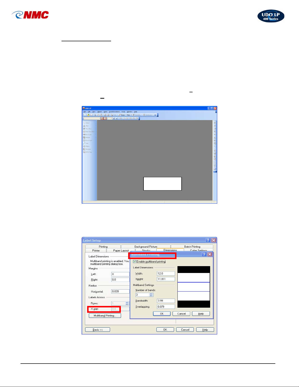
Fig. 13
Fig. 14
Label Area
2. Double Click on the label area (Fig. 13); a Label Setup box will open. Click
on the ‘Dimensions’ tab (Fig. 14)
LP400 User Guide (11/07)
37
Page 38
UDO LP400 User Guide
_____________________________________________________________________________________________________
3. Click the ‘Multi-band Printing’ button (Fig. 14). In the Multi-band Printing
dialogue box, click on the box beside ‘Enable M
ulti-band Printing’ to select
this option.
4. Change the number of bands to the required quantity. In this example use 3.
5. Change the ‘O
verlapping’ to .079” This field specifies the amount of space
on the label which overlaps with the neighboring label.
6. Make sure the ‘B
andwidth’ is exactly 3.937”.
7. Notice that the label ‘He
ight’ changes under the ‘Label Dimensions’ (e.g. 2
bands – 7.874”; 3 bands - 11.653”; etc.)
8. Under ‘Label Dimensions’ choose the desired ‘W
idth’.
9. Click ‘OK’ in the Multi-band Printing Dialogue Box. Click ‘OK’ in the Label
Setup box.
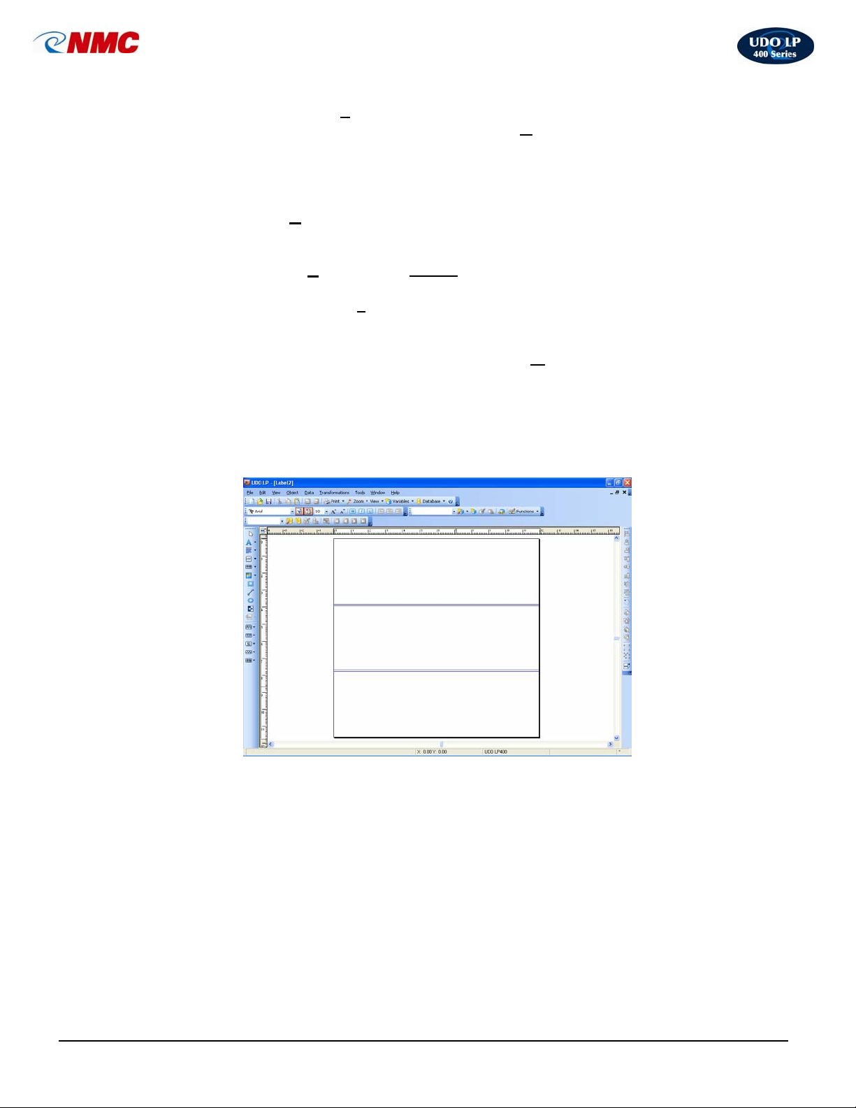
10. The screen will adjust the widths and display the bands on screen (Fig. 15).
Fig. 15
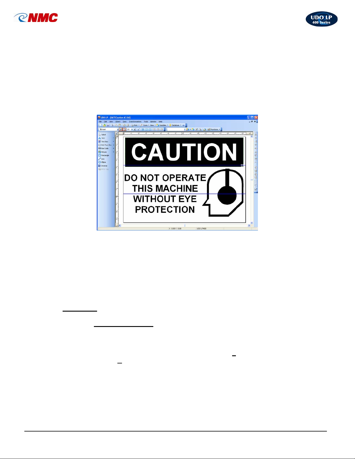
11. Create the label using all 3 bands for your label area (Fig. 16).
12. Click the ‘Text’ tool then click in the label area. Type “CAUTION”. Resize
the text by clicking and dragging on one of the handles around the text box.
13. Click the ‘Inverse’ tool. Click in the upper left corner of the text. Adjust size
of inverse box as necessary by clicking and dragging on one of the handles
around the text box.
14. Click the ‘Picture’ tool. Click in the label area. A dialog box will open.
15. Click on ‘Clip Art Gallery’ button in the lower right. Click the ‘+’ button next
to ‘Symbols USA’. Scroll down to the ‘PPE’ category. Select the ‘ear
LP400 User Guide (11/07)
38
Page 39
UDO LP400 User Guide
_____________________________________________________________________________________________________
protection symbol’ (top row, 5th image from the left). Click ‘OK’. Resize the
image by clicking and dragging on one of the handles around the image.
16. Click the ‘Text’ tool. Click in the label area. Type “DO NOT OPERATE THIS
MACHINE WITHOUT EYE PROTECTION”. Resize as necessary by clicking
and dragging on one of the handles around the image.
17. Select ‘Print’ from the menu bar.
Fig. 16
18. The UDO LP400 will print out in multiple strips of your vinyl label. Line up the
sections to produce the Tiled Label.
Tips for Applying Labels
i. Use an application spray of soap and water with a squeegee.
ii. Lay the bottom strip first.
iii. Each strip overlaps per your setting; in this example the
overlapping is 0.079”.
J. Barcoding
2. Inserting a Barcode
To insert a barcode on to a label, proceed as follows:
1. Click on the ‘Create New Label’ icon or choose ‘F
then select ‘N
2. Select the ‘Barcode’ tool which appears on the left side toolbar and click in
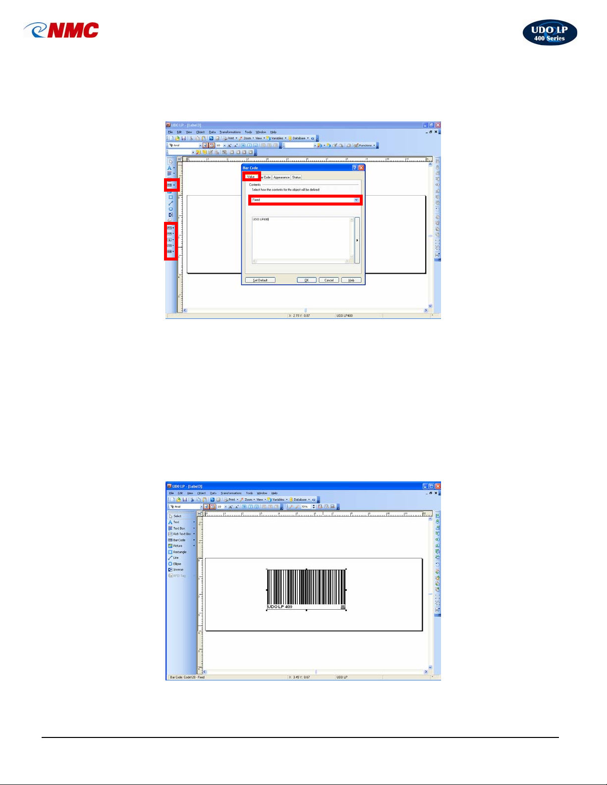
the label area. A Bar Code dialogue box will open (Fig. 17). This box contains
the options available for entering and editing the appearance of your barcode.
3. Click the ‘Bar Code’ tab. Choose the type of barcode you wish to insert from
the drop down list.
ew’.
ile’ from the menu bar
LP400 User Guide (11/07)
39
Page 40
UDO LP400 User Guide
_____________________________________________________________________________________________________
4. ‘Click’ on the Value tab and ‘select’ Fixed as your defined object (Fig. 17).
(Use this box to insert the
text you wish to print on
your label.)
Fig. 17
5. In the box which appears below ‘Fixed’ (Fig. 17), enter the text you wish to
appear on your label. Click ‘OK’; your barcode and text will appear as
shown in Figure 18.
6. Adjust the size and location of your barcode using the handles on the
selected box (Fig. 18).
7. To change settings or see options, double Click on the inside of your
barcode to open the Barcode dialogue box. You can also right click and go
to ‘Barcode Properties’ to open the ‘Barcode’ dialogue box.
Fig. 18
LP400 User Guide (11/07)
40
Page 41

UDO LP400 User Guide
_____________________________________________________________________________________________________
3. Setting up a variable
1. Click ‘D
dialog box will open. Click the ‘N
ata’ in the menu bar at the top of the screen. Select ‘Variables’. A
ew’ button. Another dialog box will open.
2. Click on the ‘A
asic << Tab is showing you are already in the Advanced dialogue
the B
dvanced’ button at the bottom left of the dialog box. (Note: If
mode.)
3. Select the ‘General’ tab. Enter a name for the label in the ‘Name’ field.
4. Adjust the length of the variable data (i.e. 01 would be 2 digits, 001 would be
3 digits, etc.) if needed.
5. Click on the ‘Serialization’ tab. Select either ‘I
‘D
ecremental Counter’ by clicking the appropriate button.
ncremental Counter’ or
6. Step refers to the number of digits to go up or down in (i.e. 1’s, 2’s, 5’s, etc.)
Adjust as necessary by using the arrow button or by typing in number.
7. Change value after the number of labels is how many labels will be printed
before the label increments/decrements. Adjust as necessary by using the
up/down arrow buttons or by typing in the number.
8. If a prefix or suffix is required, click on the ‘Data Processing’ tab and enter
the information in the relevant box.
9. Click on ‘Prompting’ tab. In the ‘Display this text to the printer operator’
field type ‘enter start number’. This is a visual aid to signal where to enter
the starting number.
10. Click ‘OK’.
4. Adding a variable to the label
1. Click on the ‘down arrow’ to the right of the ‘Text’ button for text only or the
‘Barcode’ tool (depending if you are doing just text or a barcode variable).
2. Select ‘Use Existing Variable’. Select the variable you created.
3. Click in the label. The variable will appear.
4. Adjust the size accordingly.
5. Editing Barcodes
Make adjustments to barcodes such as the style of barcode, removing the check
digit, amending the size of the text beneath the barcode or hiding the text to
show just the barcode.
LP400 User Guide (11/07)
41
Page 42
UDO LP400 User Guide
_____________________________________________________________________________________________________
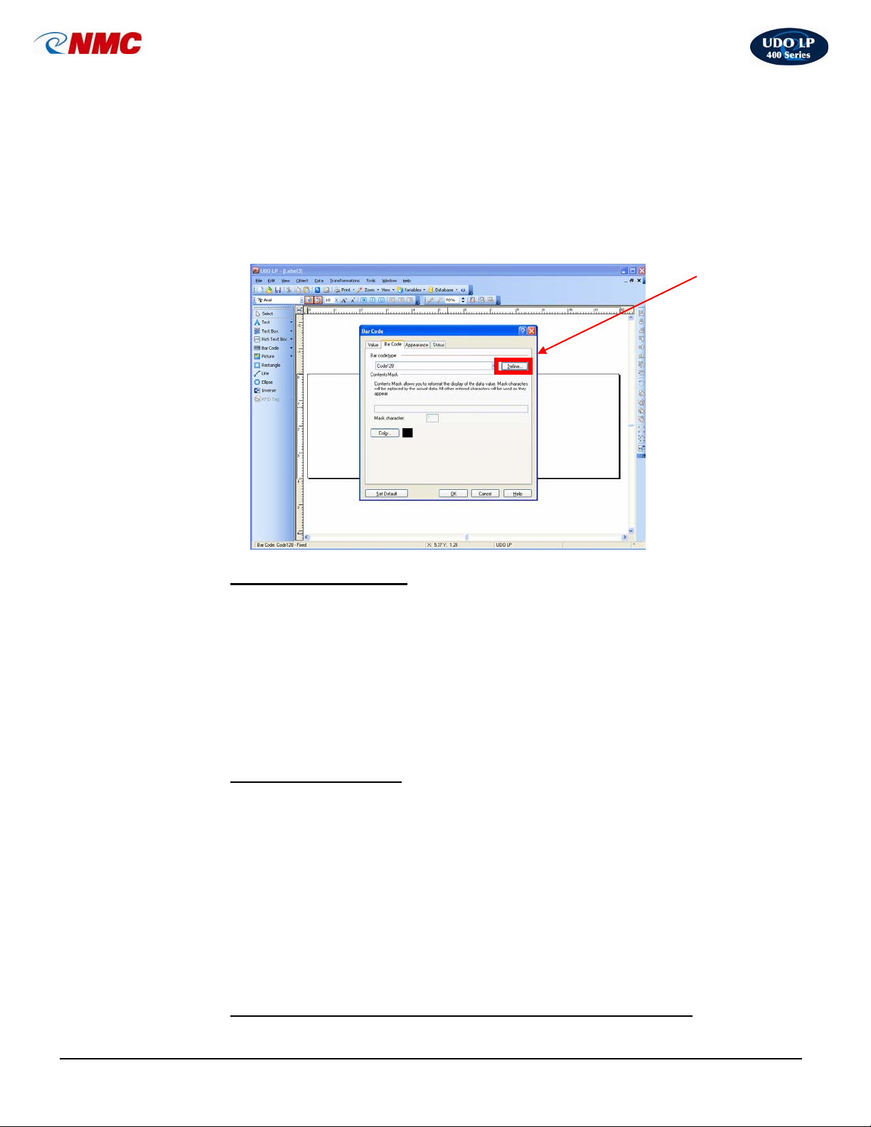
1. Double Click on the inside of the barcode to open the ‘Barcode Dialog Box’
(Fig. 19). You can also right click and select ‘Bar Code Properties’ to open
the ‘Barcode Dialogue Box’.
2. Click on the ‘Bar Code’ tab. Click on the ‘Define’ box. (Fig. 19).
3. Make adjustments as necessary.
Fig. 19
6. Changing barcode style
1. Double Click on the inside of the barcode to open the ‘Barcode Dialog Box’
(Fig. 19). You can also right click and select ‘Bar Code Properties’ to open
the ‘Barcode Dialogue Box’.
2. Click on the ‘Bar Code’ tab. Click on the ‘Define’ box. (Fig. 19).
3. Under the ‘General’ tab choose from the available bar codes listed on the
left. Click ‘OK’.
7. Changing barcode font
1. Double Click on the inside of the barcode to open the ‘Barcode Dialog Box’
(Fig. 19). You can also right click and select ‘Bar Code Properties’ to open
the ‘Barcode Dialogue Box’.
2. Click on the ‘Bar Code’ tab. Click on the ‘Define’ box. (Fig. 19).
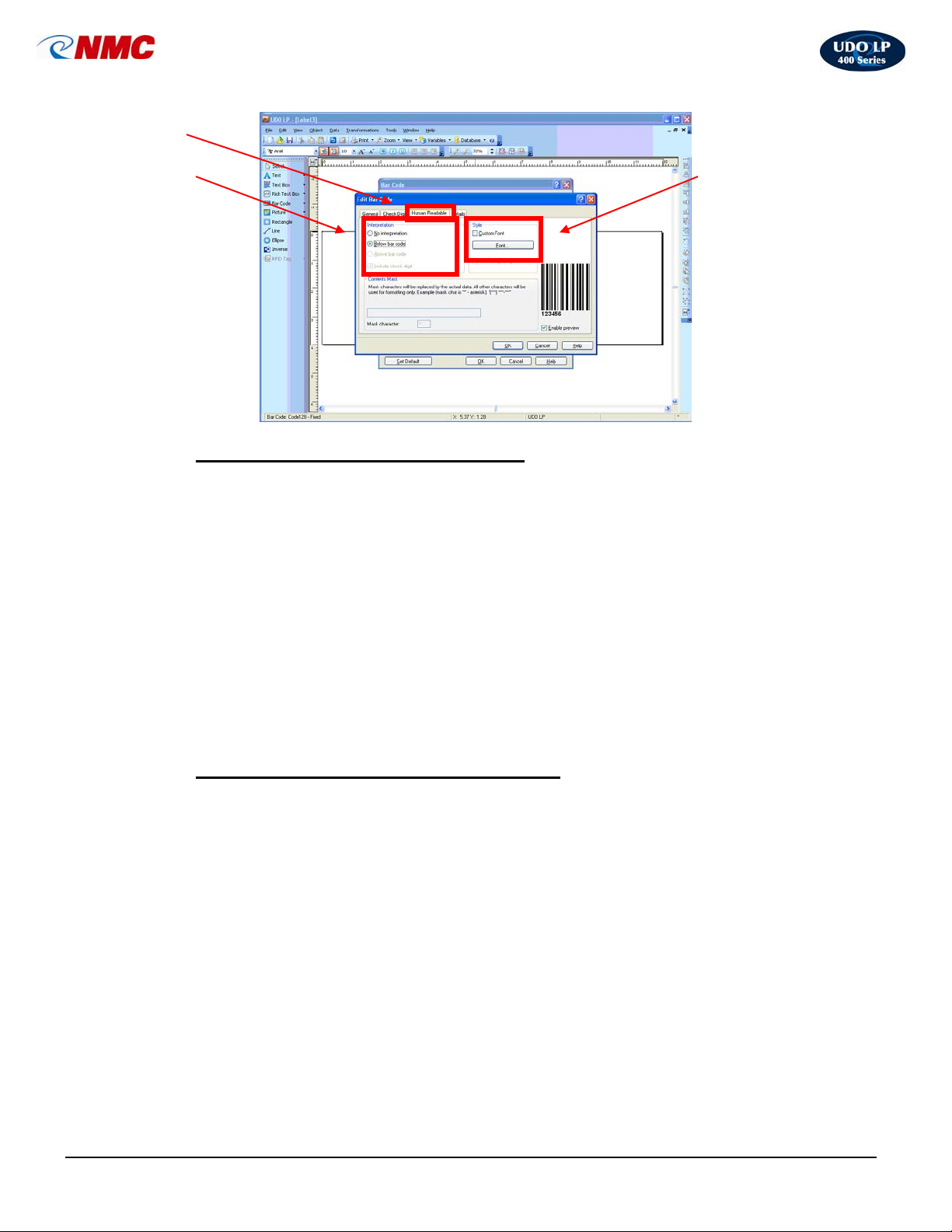
3. Click on ‘Human Readable’ tab.
4. Click the ‘Font’ button. (Note: If the font option is greyed out, go to the
‘General’ tab and Check the ‘Print Barcode as a Graphic’ option.) Select
appropriate font settings. Click ‘OK’.
8. Changing the text size beneath the barcode (if too small/large)
LP400 User Guide (11/07)
42
Page 43

UDO LP400 User Guide
_____________________________________________________________________________________________________
1. Double Click on the inside of the barcode to open the ‘Barcode Dialog Box’
(Fig. 19). You can also right click and select ‘Bar Code Properties’ to open
the ‘Barcode Dialogue Box’.
2. Click on the ‘Bar Code’ tab. Click on the ‘Define’ box. (Fig. 19).
3. Under the ‘General’ tab, Click the ‘Print Barcode as a Graphic’ option
4. Click on ‘Human Readable’ tab see (Figure 20).
5. If checked
, Un-check the ‘Auto Font Scaling’ option.
6. Click on the ‘Font’ and select the size and font. Click’OK’.
h. Removing a “Check Digit”
This tab is used to specify the use of the check digit in the bar code. This option
can only be modified for the bar codes that allow you to enable and disable
the check digit.
Some bar code standards include the check-digit by the definition and it cannot
be omitted. Examples of these bar codes are: EAN and UPC bar codes, where
check digit cannot be disabled at all. (Note: It is always recommended to include
the check digit character in the bar code. It will increase the scanning reliability.)
1. Double Click on the inside of the barcode to open the ‘Barcode Dialog Box’
(Fig. 19). You can also right click and select ‘Bar Code Properties’ to open
the ‘Barcode Dialogue Box’.
2. Click on the ‘Bar Code’ tab. Click on the ‘Define’ box. (Fig. 19).
3. Click on the ‘Barcode’ tab. Click ‘Define’.
4. Click on the ‘Check Digit’ tab and deselect the check digit option by
clicking ‘Include Check Digit’.
LP400 User Guide (11/07)
43
Page 44
UDO LP400 User Guide
_____________________________________________________________________________________________________
Fig. 20
i. To change the text beneath the barcode:
1. Double Click on the inside of the barcode to open the ‘Barcode Dialog Box’
(Fig. 19). You can also right click and select ‘Bar Code Properties’ to open
the ‘Barcode Dialogue Box’.
2. Click on the ‘Bar Code’ tab. Click on the ‘Define’ box. (Fig. 19).
3. Click on ‘Print Bar Code as a Graphic’.
4. Click the ‘Human Readable’ tab and deselect the Auto Font Scaling option
by clicking on ‘Auto Font Scaling’. (Figure 20).
5. Click on the ‘Font’ button and adjust the font and/or size of text. Click ‘OK’.
Click ‘OK’ again in the ‘Edit Bar Code Dialog’ box.
j. To hide/unhide the text beneath the barcode:
1. Double Click on the inside of the barcode to open the ‘Barcode Dialog Box’
(Fig. 19). You can also right click and select ‘Bar Code Properties’ to open
the ‘Barcode Dialogue Box’.
2. Click on the ‘Bar Code’ tab. Click on the ‘Define’ box. (Fig. 19).
3. Click on the ‘Human Readable’ tab.
4. If you don’t want the information to be shown, Click on ‘No Interpretation’.
Leave as ‘Beneath Barcode’ if the information is to be displayed.
LP400 User Guide (11/07)
44
Page 45
UDO LP400 User Guide
•
•
•
•
•
•
_____________________________________________________________________________________________________
Trouble Shooting
When a problem with the printer occurs, the POWER and/or READY lights will keep blinking.
Printing and communication between the computer and printer will stop. To understand what the
problem is, first look at the lights on the front of the printer. To continue print jobs after any
abnormal conditions have been resolved, simply press the panel feed button or switch the printer
off for 10 seconds then switch it on again. Make sure that the light is not blinking and reprint your
label.
POWER and READY Lights blink at the same time
Possible Problems Solutions
• Vinyl roll is empty
• Vinyl roll is not installed properly
• Label jam
Replace vinyl roll
• Re-install label roll properly
• Remove the jam
POWER and READY Lights Blink Alternately
Possible Problems Solutions
• Empty Ribbon cartridge
• Ribbon jam
Replace ribbon
• Remove the jam
Only the POWER Light blinks
Possible Problem Solution
• Cutter failed or jam at the cutter
• Hardware error
Check the cutter and remove any
jams
• Call NMC at (800) 453.2727 for
service
The computer shows “Printer Time Out” error message
Possible Problem Solution
• USB or power connection failed
Check all cable connections.
Confirm power is on and
connected properly to printer
The data has been sent, but nothing prints
Possible Problem Solution
• Printer is off
• Wrong printer is active
Turn on the printer
• Check ‘Printers and Faxes’ in the
Control Panel
Horizontal or Vertical streaks in the printout
Possible Problem Solution
• Dirty print head, ribbon or vinyl
• Vinyl or ribbon has been over
handled or left out of its bag
Clean the print head and platen
roller thoroughly using the cleaning
pen supplied
• Advance the vinyl or ribbon 1” – 2”
and reprint
LP400 User Guide (11/07)
45
Page 46
UDO LP400 User Guide
•
•
_____________________________________________________________________________________________________
Half of the label prints faded or only half of the label prints
Possible Problem Solution
• Print head not clicked in firmly on
both sides
Open and close the print head
making sure both sides click in
place.
Abnormal print out with lines or scratches
Possible Problem Solution
• Damaged ribbon (creased,
folded,scratched)
Advance and check ribbon. Make
sure it is taut.
Recovery
In order to continue your print jobs after any abnormal conditions have been recovered,
simply press the panel button or switch the printer off for 10 seconds and then switch the
power on again. Make sure that the LED is not blinking and remember to resend your
files.
Maintenance
Before performing any maintenance on the printer, please be sure to turn off the
printer power.
Cleaning the print head
1. Turn off the printer. Open the top cover and release the print head by pressing
the two purple buttons.
2. Remove the ribbon
3. Using the Thermal Cleaning Pen provided (included in starter kit #UPCP724)
wipe from left to right, ensuring all visible traces of adhesive and ribbon deposits
are removed. Do not
Note: The print head should be cleaned at least every time the ribbon is replaced or if
there is any deterioration in print quality ie. lines, speckles.
Cleaning the printer exterior
1. Use a soft, damp cloth to wipe the printer exterior
wipe the print head back and forth.
LP400 User Guide (11/07)
46
Page 47
UDO LP400 User Guide
_____________________________________________________________________________________________________
General Printer Specifications
Print Technology Thermal Transfer
Resolution 203 DPI (dots per inch) 8 dots/mm
Maximum Print Width 4.10 in. (104mm)
Maximum Print Length 45 in. (1143mm)
Printer Speed 1” – 4” per second, default set for optimum
print quality at 1.5”/sec.
Onboard RAM 2 MB DRAM and 2MB Flash ROM
Media Type Vinyl, Polyester and Paper materials on
Continuous Roll and Die-Cut format
Label Roll Dimensions 4” Max. Label Width and 82’ Max. Roll
Length
Ribbon Type Resin, Wax, Wax/Resin
Ribbon Size 4 1/3” Width x 298’ Length (White 230’)
Interface USB 2.0
Dimensions W 7.3” x D 10.9” x H 6”
Weight 4.1 lbs.
Electrical FCC Class B, CE, UL and CUL approved.
Input 19 VAC or 24 VDC (min. 2.5A), 50/60
Hz
Operating Temperature
°~140°F (5° ~ 38°C)
40
Storage Temperature -40° ~ 140°F (-40° ~ 60°C)
Humidity 15 ~ 85% RH
Operating System Windows 95, 98, NT, NT4, 2000, XP,
Vista,7
Rotation 1° Increments
WEEE-RoHS Compliant Yes
Warranty 1 year Parts and Labor
LP400 User Guide (11/07)
47
 Loading...