

Page 1

0 Wireless Gateway
1
2
3
4
5
6 User's Guide
7
8
Rev. 01 (Oct., 2001)
Page 2

FCC Warning
This equipment has been tested and found to comply with the limits for a Class A
digital device, pursuant to Part 15 of the FCC Rules. These limits are designed to
provide reasonable protection against harmful interference when the equipment is
operated in a commercial environment. This equipment generates, uses, and can
radiate radio frequency energy and, if not installed and used in accordance with this
user’s guide, may cause harmful interference to radio communications. Operation of
this equipment in a residential area is likely to cause harmful interference in which
case the user will be required to correct the interference at his own e xpense.
CE Mark Warning
This is a Class A product. In a domestic environment, this product may cause radio
interference in which case the user may be re quired to take adequate measures.
2
Page 3

9 Table of Contents
10 1. Introduction ........................................................................5
11 Features................................ ...................................................... 5
12 2. External Components ........................................................7
13 Back Panel................................ .................................................7
14 Front Panel................................ .................................................8
15 3. Web Configuration ..........................................................10
16 Basic Setup ................................ ..............................................12
17 Broadband Router................................................................................13
18 Wireless AP..........................................................................................17
19 Print Server ..........................................................................................19
20 Admin Password..................................................................................21
21 Advanced Settings................................ ....................................22
22 DHCP Server........................................................................................23
23 Port Forwarding ...................................................................................27
24 Port Open .............................................................................................30
25 Routing.................................................................................................33
26 Filters ...................................................................................................37
27 Manager Console .................................................................................41
28 Wireless Access ...................................................................................45
29 Wireless Encryption .............................................................................47
30 Wireless Bridge .................................................................................... 50
31 Information ................................ ..............................................54
32 Device ..................................................................................................55
33 DHCP ...................................................................................................56
34 Routing.................................................................................................57
35 Users.....................................................................................................58
36 Connections..........................................................................................59
37 WAN Link............................................................................................60
38 Printer Status........................................................................................61
39 Wireless Stations..................................................................................62
40 Wireless Tallies....................................................................................63
3
Page 4

41 Tools................................ ........................................................65
42 Reset.....................................................................................................65
43 Factory Reset........................................................................................66
44 Print Test ..............................................................................................66
45 PPPoE Connect and PPPoE Disconnect ..............................................66
46 Help ................................ .........................................................68
47 4. Appendix............................................................................69
48 Device Utility................................ ...........................................69
49 Installation............................................................................................69
50 Using Device Utility ............................................................................70
51 Changing IP Address ...........................................................................71
52 Firmware Upgrade ...............................................................................71
53 Specifications................................ ........................................…72
4
Page 5

1
Introduction
Thank you for purchasing the Wireless Gateway with Ethernet switch, wireless access
point, and print server. It is the ideal all-in-one solution for any home or small office
with a need for high-speed shared Internet access, wireless station support, and
network-based printing.
This guide describes the Wireless Gateway and explains how to configure and install
it. Because the Wireless Gateway supports many complex technologies, and because
requirements differ greatly from location to location, the Wireless Gateway should be
configured and installed by competent technical personnel familiar with the
networking environment it will be used in.
Features
Hardware Features:
• 10-Mbps Ethernet WAN (wide -area network) port for connection to a
broadband (DSL or cable) modem or router
• IEEE 802.11b wireless access point (AP)
• Four switched, dual-speed (10/100-Mbps) Ethernet ports
• Uplink port for convenient connection to an upstream hub or switch
• Speed-adjustable parallel port for connection to printer
Capabilities:
• Built-in Web-based configuration utility
• Configurable for a fixed-IP, DHCP -based, or PPPoE WAN connection
• Configurable WAN port MAC address
5
Page 6

• Full selection of wireless channels (number depends on region of sale)
• Supports TCP/IP and AppleTalk printing protocols
• Configurable as a DHCP (Dynamic Host Configuration Protocol) server
• “Port Forwarding” function for outside access to specified local servers
• “DMZ Host” function
• “Port Open” function for control of Internet gaming
• Configurable for NAT or router mode
• Up to sixteen static routes, individually configurable for LAN or WAN
interface
• Configurable for dynamic routing on LAN and/or WAN
• Per-interface, per -direction RIP (Routing Information Protocol) selections
(RIP 1, RIP 1-compatible, RIP 2, no RIP)
• LAN-to-WAN access control on basis of IP or MAC address or both
• LAN-to-WAN access control on basis of protocol (port number)
• NetBIOS over TCP/IP blocking function
• WAN request blocking function (to reject potentially harmful requests
originating on the WAN)
• Connection scheduling, logging, and filtering (requires Manager Se rver
software)
• Flexible MAC-based wireless access control
• IEEE 802.11b WEP encryption with up to four 64- and/or 128-bit keys
• Configurable protocol-based filtering between wired and wireless segments of
the LAN
• Global or per -host filtering of wired-to-wireless broadcasts and multicasts
• Extensive reporting capabilities
6
Page 7
2
External Components
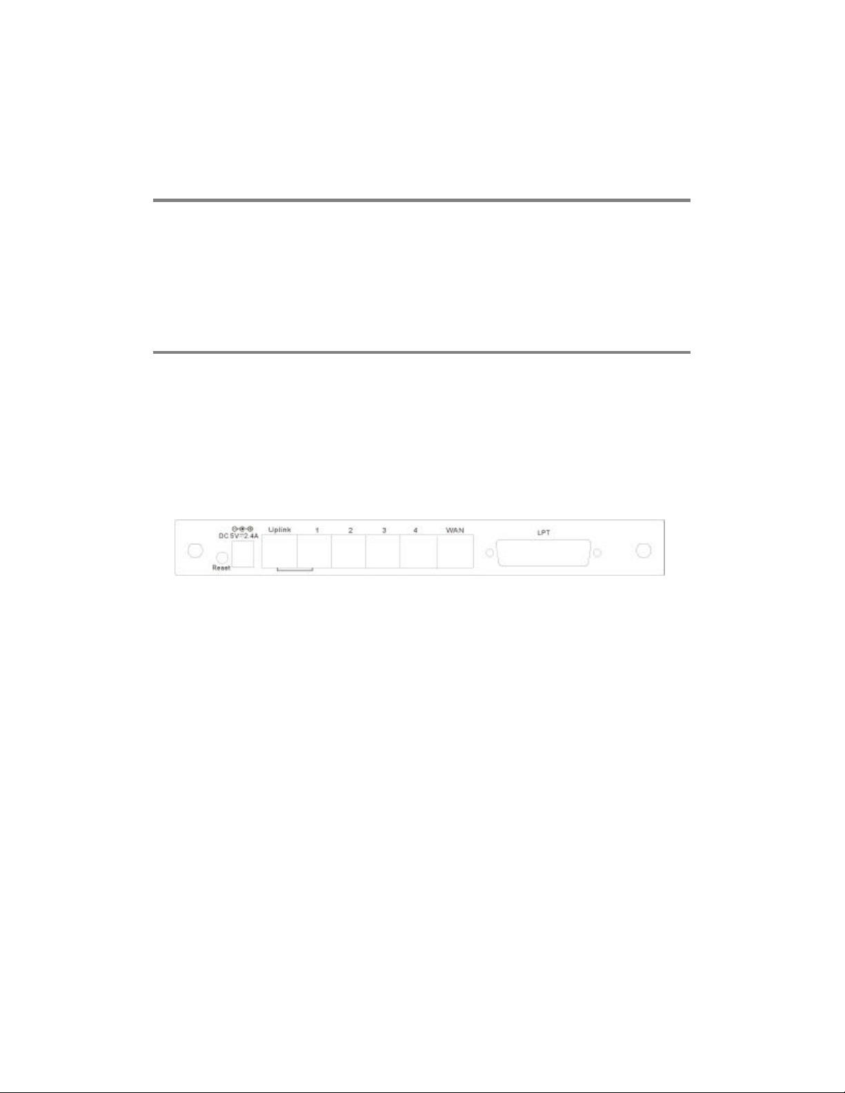
This section describes the back and front panels of the Wireless Gateway in details.
Back Panel
Following are explanations of the items on the Wireless Gateway's back panel:
• Antennae: The antennae at the back panel carry radio -frequency signals
between wireless stations and the Wireless Gateway's wireless bridge (the
interface between the wireless and wired parts of the LAN).
•
Reset button:
the LPT LED begins to flash. Factory Reset will be initiated when the reset
button is pressed continuously for three seconds or when the LPT LED begins
to light up. Release the reset button and the LPT LED will begin to flash
indicating the Wireless Gateway is changing to factory reset. When factory
reset is completed the Wireless Gateway will be set to default on channel 11
with default IP address as 192.168.0.254 and EES-ID is set as ‘default’.
• DC Input: For connection to the DC 5V power adapter.
•
Uplink port:
switch with an ordinary “straight-through” (as opposed to cross-wired)
Ethernet cable. This port and the LAN port next to it cannot be used at the
same time; they are simply differently wired ports for LAN port 1.
Reset will be initiated when the reset button is pressed once and
For connecting the Wireless Gateway to an upstream hub or
7
Page 8
Note: All connections to the Wireless Gateway's LAN ports
should be made with Category 5 Ethernet cabling. Lower-grade
cabling cannot reliably carry 100-Mbps signals.
• LAN ports 1 through 4: Sw itched, auto-negotiating 10/100-Mbps Ethernet
ports for connecting end nodes (or downstream hub- or switched-based
clusters of end nodes) to the Wireless Gateway.
• WAN port: 10-Mbps Ethernet port for connection to a DSL or cable modem
or router.
• Parallel port: A Centronics-type connector for a standard printer cable.
Front Panel
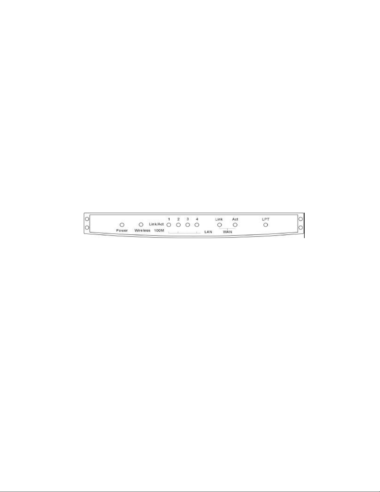
The Wireless Gateway's LED indicators are located on the unit's front panel:
• Power: Illuminates whenever the unit has power.
• Wireless: Illuminates when the wireless AP (access point) is ready but idle;
flashes when there is activity on the wireless link.
• LAN 1 to LAN 4 Link/Act: Each of these indicators illuminates when there is
a good but idle link on the corresponding LAN port, flashes when packets are
received/transmitted on the link.
• LAN 1 to LAN 4 100M: Each of these indicators illuminates when the
corresponding LAN port is operating at 100 megabits per second.
• WAN Link: Illuminates when there is a good link on the WAN port.
• WAN Act: Illuminates whenever unit has power, flashes when there is
activity on the WAN port.
• LPT: Flashes three times then goes off to indicate a successful Power-On
Self-Test. Flashes on and off later during normal operation when there’s
printing activity. If the self-test detect any component error, then the LPT LED
will continuously signal the error according to the following table. In the
event of any such error signal, contact your dealer for correction of the faulty
unit.
8
Page 9

•
LPT LED
low speed flashing
on
Need Reload Firmware
Faulty
Component
DRAM error
1 long 2 short Timer INT error
1 long 3 short Flash Protected
1 long 5 short Flash Erase/Program error
1 long 6 short LAN Controller error
1 long 7 short LAN Memory error
1 long 8 short WAN or LPT Controller error
1 long 9 short WAN Memory or LPT error
1 long 11 short LAN IO Base error
1 long 12 short WAN IO Base error
1 long 14 short LAN MII error
•
1 long 15 short WLAN Connector error
1 long 16 short WLAN CIS error
1 long 17 short WLAN IO error
9
Page 10

Web Configuration
The Wireless Gateway must be configured through its built-in Web-based
configuration utility. Before attempting to access this utility, note the following
factory defaults:
• WAN interface defaults: IP address 192.168.100.254, address mask
255.255.255.0. DHCP (Dynamic Host Configuration Protocol) client and
PPPoE (Point-to-Point Protocol over Ethernet) functions are off.
• LAN interface defaults: IP address 192.168.0.254, address mask
255.255.255.0. DHCP server function is on and will assign addresses in t he
range of 192.168.0.101 through 192.168.0.150.
• General defaults: No administrator password is set. Requests received
3
through the WAN port (including “ping” requests and HTTP requests to the
built-in Web-based configuration utility) are disabled.
The requ irements for configuring the Wireless Gateway are (1) a computer equipped
with an Ethernet interface and a recent, frames-capable, Javascript -enabled World
Wide Web browser, and (2) an Ethernet cable.
You will also need extensive knowledge of the LAN and the broadband link that the
Wireless Gateway will be connected to.
The recommended way to connect the Wireless Gateway for configuration is as
follows:
1. Connect the computer to one of the LAN ports on the back panel of the
Wireless Gateway's LAN ports with t he Ethernet cable (NOT the uplink port).
Do not make any other connections to the Wireless Gateway.
2. Set the computer to use an IP address in the range of 192.168.0.1 through
192.168.0.253 and an address mask of 255.255.255.0.
10
Page 11

Note: If the operating system or the browser is set to use an
HTTP proxy server, either turn off the setting or put the
Wireless Gateway's IP address in the list of unproxied hosts.
3. Power up the Wireless Gateway and wait about 15 seconds while it boots up.
4. Command the browser to access the following URL:
http://192.168.0.254/
Note: If you have accessed the configuration utility and changed the IP address of
the Wireless Gateway before, use the factory reset button to reset the unit. Or
alternatively, you can enter the new IP address as the URL and make sure the
computer use a corresponding IP address. For example, if you have changed the
IP address to 172.16.100.1, use it as the URL and make sure the computer have an
IP address in the range of 172.16.100.2 through 172.16.100.254. In addition, if
you have changed the subnet mask, the computer must have the same subnet mask
too.
The configuration utility's initial display will appear and divide the browser window
into three sections:
• A
menu bar
at the top of the window contains the names of the utility's
top-level menus. This bar never changes.
• A
command panel
at the left edge of the window contains the commands in
the current menu.
• A
settings panel
occupying the rest of the window contains either butt ons,
input boxes, and other controls for changing device settings, or information
about the Wireless Gateway.
The following sections explain the items in the settings panels under each of the
configuration utility's menus.
11
Page 12

Basic Setup
The settings panels under the Basic Setup menu contain settings that almost always
must be adjusted to let the Wireless Gateway operate at all. Four settings panels can
be accessed from the Basic Setup menu:
• Broadband Router
• Wireless AP
• Print Server
• Admin Password
12
Page 13
Basic Setup — Broadband Router
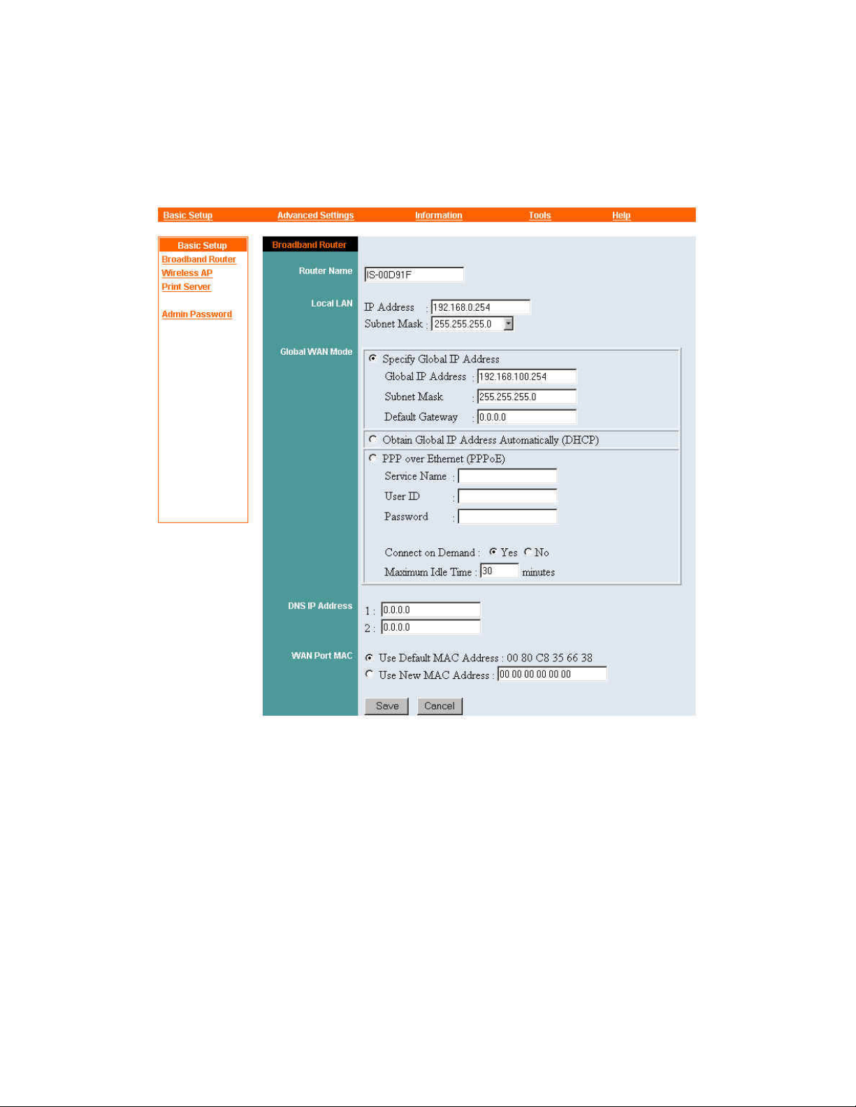
The Basic Setup menu's Broadband Router panel is the first to appear whenever the
configuration utility starts up. The controls in this panel are explained below.
Router Name
The Router Name is a text string that some ISPs require as a means of
identification. The setting is ignored if the ISP does not require it. It is most
often required on DHCP-based links, where it is sometimes referred to as the
DHCP client's (that is, the Wireless Gateway's) “host name.” If the ISP
requires this item, click in the Router Name input box and enter the correct
name as shown in the materials received from the ISP.
Local LAN
13
Page 14

The Local LAN settings are the IP address and subnet mask that will identify
the Wireless Gateway to the other machines on your LAN. The address must
be unique on the LAN, that is, assigned exclusively to the Wireless Gateway;
the subnet mask must be the same for all machines on the LAN that will
communicate directly with the Wireless Gateway. Be sure to keep a record
of the address you set here. This will be the “default gateway” for other
machines on the LAN.
Before setting IP addresses, note that no machine must ever be assigned an
address ending in zero (that is, x.x.x.0) or 255. An IP address ending in zero
identifies an ent ire network, not a particular machine. An IP address ending in
255 is a “broadcast” address, used for sending messages to all the machines on
a network at the same time.
Note also that possible subnet mask settings for the LAN interface are of the
form 255.255.255.x, where x can be 0, 128, 192, 224, 240, 248, or 252. The
installing technician will recognize that this makes the Local LAN settings
suitable for a Class C IP network or a subnet of such a network.
In the case that ISP give you a single globally legal IP address to be assigned
to the Wireless Gateway's WAN port, you will have to use what are called
“private addresses” on the LAN.
An example of a private address is 172.16.0.0. This is a network address;
individual machines on a LAN using this network address can be assigned
addresses in the range of 172.16.0.1 through 172.16.0.254. (This assumes that
all machines on the LAN use a subnet mask of 255.255.255.0; using any other
mask requires extensive technical knowledge and is beyond the scope of this
guide.)
The following three IP address blocks have been set aside by Internet
regulatory authorities specifically for local-only use:
10.0.0.0 through 10.255.255.255
172.16.0.0 through 172.31.255.255
192.168.0.0 through 192.168.255.255
Global WAN Mode
14
Page 15

The Global WAN Mode controls must be adjusted as required by your ISP.
The settings you enter here determine how the Wireless Gateway will be
identified to your ISP's equipment and other machines on the global Internet.
• If your ISP has given you a fixed IP address to use on the WAN link,
click the Specify Global IP Address control. Then click in (or tab to)
the three boxes below it and type in the global IP address, subnet mask,
and default gateway that the ISP has instructed you to use.
• If your ISP will assign the Wireless Gateway an IP address and related
settings using DHCP (the Dynamic Host Configuration Protocol),
simply click Obtain Global IP Address Automatically (DHCP) .
DHCP is commonly used on cable links.
• If your ISP uses PPPoE (the Point-to-Point Protocol over Ethernet),
click the PPP over Ethernet (PPPoE) control. The ISP will have
given you a “username” or user ID and a password to use on the
PPPoE link; click in (or tab to) the corresponding boxes under this
control and type in the strings yo ur ISP has instructed you to use. In
some cases — especially if the Wireless Gateway's WAN port is
networked directly to more than one broadband modem or router —
you will need to type an identifying string into the Service Name box.
Your PPPoE link might allow you to save on connection charges by
disconnecting when the link is not in use and reconnecting when
someone on the LAN wants to access the Internet. If this is the case,
you have the option of setting the Connect on Demand control to Yes
or No. If you click No, you will have to use the
PPPoE Disconnect commands in the Tools menu to take the Wireless
Gateway on line and off line. (You can, alternatively, use the Manager
Server software to set a connection schedule; see the Manager Server
manual for details.) If you click
Time control also. The Wireless Gateway will then automatically
disconnect whenever the specified amount of time passes without
anyone on the LAN accessing the Internet.
DNS IP Add resses
, be sure to set the
Yes
PPPoE Connect
Maximum Idle
and
In almost all cases your ISP will provide you with the IP addresses of two or
more DNS (Domain Name System) servers. Click in the boxes provided and
type in the addresses carefully. If you set the Wireless Gateway up as a DHCP
15
Page 16

server for the machines on your LAN, it will pass the addresses to those
machines as part of the automatic configuration process. (If the Wireless
Gateway will not act as a DHCP server, you might need to set the DNS server
addresses on each of the machines individually.)
WAN Port MAC
A MAC (Media Access Control) address is a globally unique identifier for an
Ethernet interface. In cases where the Wireless Gateway is a replacement for a
computer or router with an existing broadband connection to an ISP, you
might need to make the Wireless Gateway use the same MAC address as the
device it replaces.
The original device should have a label with the device's MAC address printed
on it. A MAC address is ordinarily written as twelve hexadecimal digits, with
or without separating spaces — for example, 0080C82F8086, 0080C8 2F8086,
or 00 80 C8 2F 80 86 (these are all different ways of writing the same address).
Only the numbers 0 through 9 and the letters A through F can appear in a
hexadecimal MAC address. Letters can be in upper or lower case;
0080c82f8086 is the same as 0080C82F8086.
Only if it is necessary to do so, click the Use New MAC Address button, and
then click in the box provided and carefully type the original device's MAC
address.
Save/Cancel
After making sure all settings in the Broadband Router panel are correct, click
Save to store the settings in the Wireless Gateway's non-volatile memory. You
can, alternatively, click Cancel (or simply exit the panel) to restore all settings
in the panel to the values last saved to or retrieved from the Wireless Gateway.
Note: If you have changed the IP address in the Wireless
Gateway's Local LAN settings, be sure, after you click Save, to
point your browser to the Wireless Gateway's new IP address
before going on.
This completes the basic setup of the Wireless Gateway as a router. You are now
ready to carry out the basic setup of the Wireless Gateway's other important functions.
16
Page 17
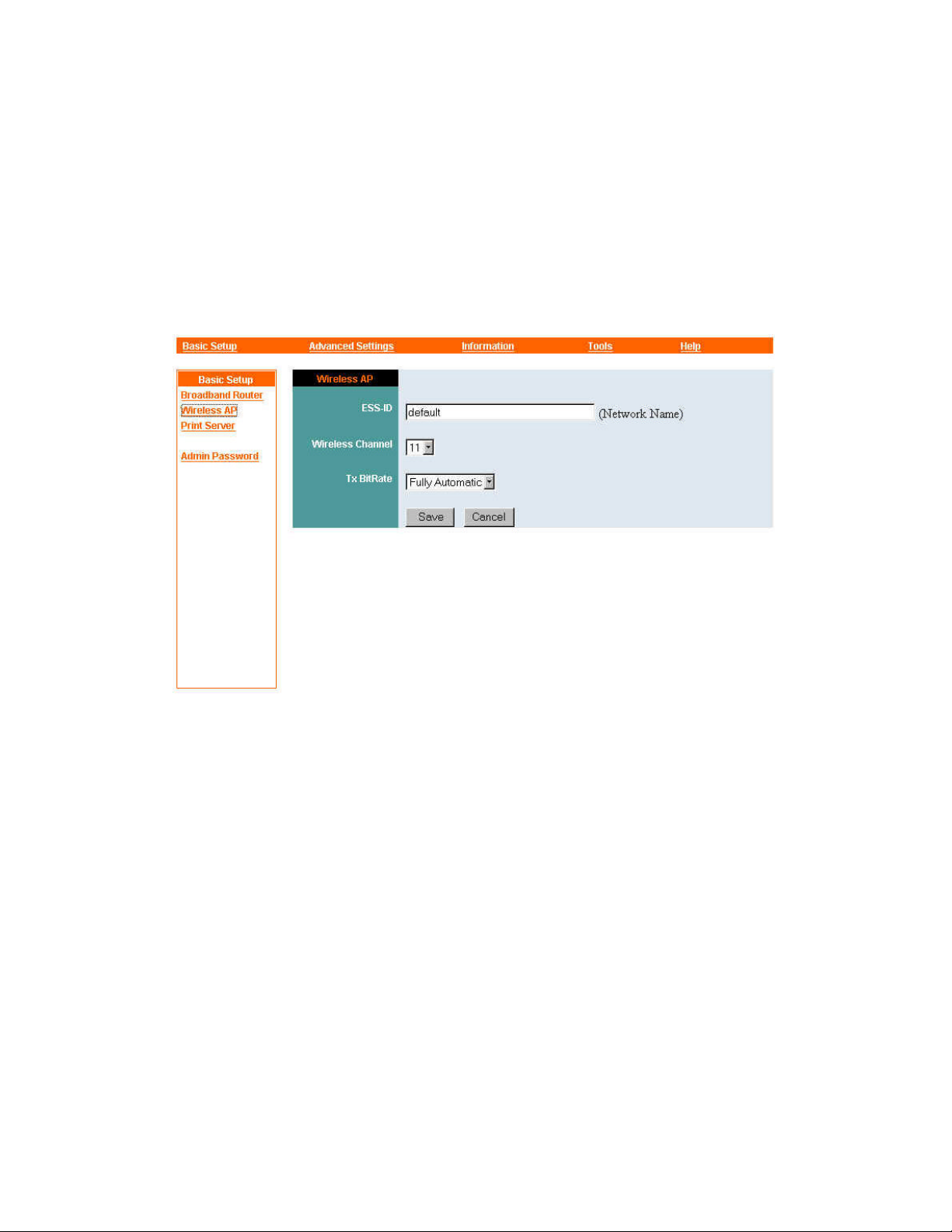
Basic Setup — Wireless AP
The Wireless Gateway's “wireless AP” is the access point — the radio-frequency
transmitting and receiving circuitry — through which wireless devices will
communicate with your LAN's wired devices and the Internet. To begin setting up the
wireless AP, click Wireless AP in the command panel at the left edge of your
browser window (if the command does not appear there, click Basic Setup at the top
of the window first).
ESS-ID
“ESS-ID” (or “ESSID”) stands for Extended Service Set ID. This is an
identifier for the network segment made up of the Wireless Gateway's wireless
AP and the wireless stations that will communicate with it. Click in the
ESS-ID box and type any string up to 32 characters long (spaces, symbols,
and punctuation are not allowed). The same string must be set as the ESS-ID
on each wireless station that will use the Wireless Ga teway as an access point.
Wireless Channel
A “channel” is a range of frequencies to be used in communication between an
AP and wireless stations. The number of channels available on the Wireless
Gateway depends on the regulatory region in which the unit was sold.
17
Page 18

If the Wireless Gateway is the only AP on your LAN, it does not matter which
channel you set the unit to use; properly configured 802.11b wireless stations
will find the correct channel automatically.
Where there are multiple APs with overlapping coverage areas, channel
assignment must be carefully planned. A good practice is to set the Wireless
Gateway to use a channel five or more channels away from that of any other
AP with a coverage area overlapping that of the Wireless Gateway. A
common scheme is to use channels 1, 6, and 11, making sure that no two APs
using the same channel have overlapping coverage areas.
Tx Bit Rate
The Tx (transmission) Bit Rate is the speed at which wireless stations and an
AP communicate. The choices are 1 , 2, 5.5, and 11 Mbps (megabits per
second), and Fully Automatic. The default setting is Fully Automatic. A
setting of Fully Automatic allows stations and the AP to adjust their speed on
the basis of signal strength and quality. A low, fixed setting might be used for
maximum reliability or to discourage the use of high-bandwidth applications
such as video and audio. A high, fixed setting will fasten the transmission
speed and ensure that only stations very close to the AP will be able to
communicate reliably with it.
Save/Cancel
After making sure all settings in the Wireless AP panel are correct, click
to store the settings in the Wireless Gateway's non-volatile memory. You can,
alternatively, click
the panel to the values last saved to or retrieved from the Wireless Gateway.
Cancel
Save
(or simply exit the panel) to restore all settings in
18
Page 19
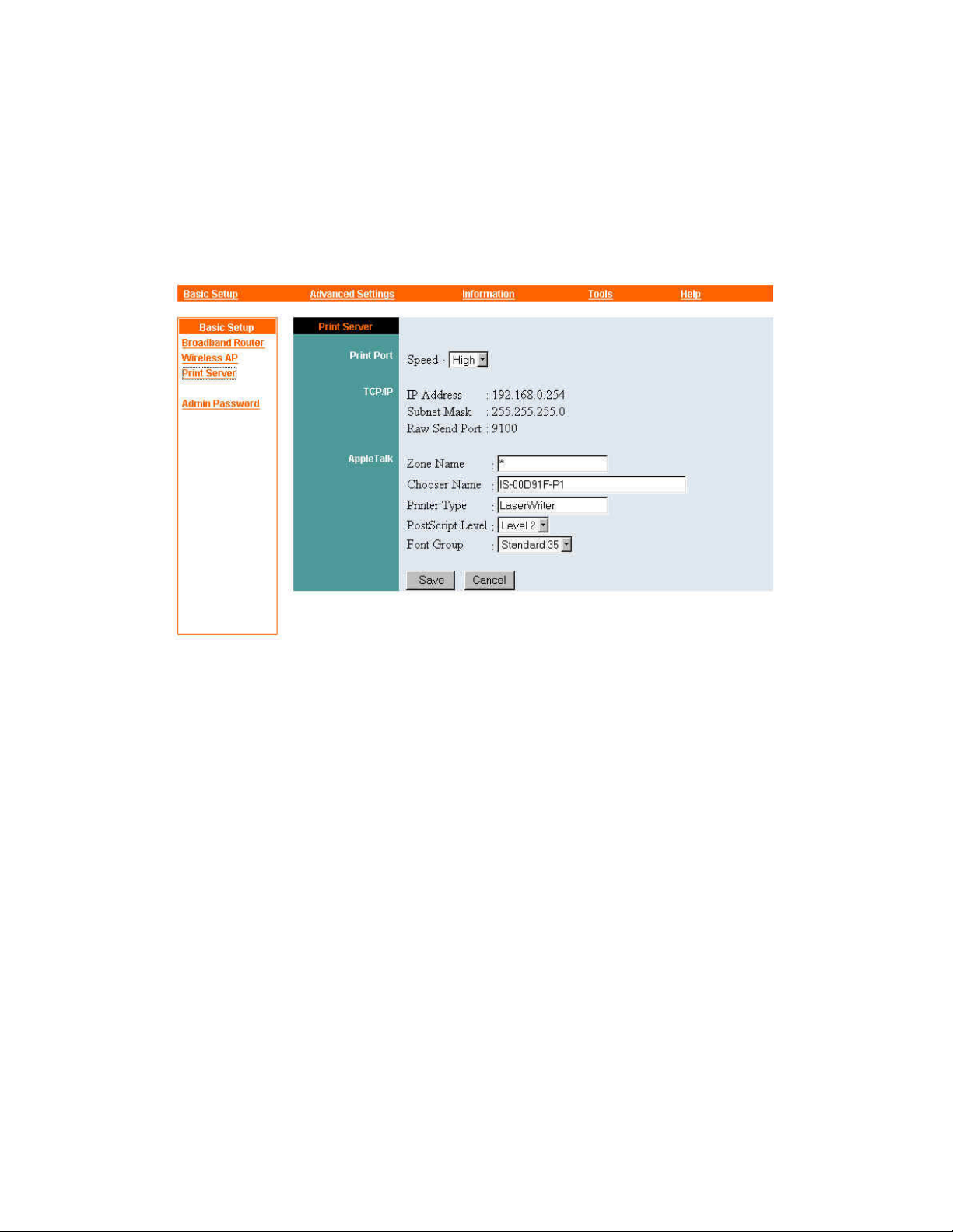
Basic Setup — Print Server
To view and adjust the Wireless Gateway's print server settings, click Print Server in
the command panel at the left edge of your browser window (if the command does not
appear there, click Basic Setup at the top of the window first). Controls in the Print
Server settings panel are explained below.
Print Port
The Print Port Speed control has two possible settings, High and Low. The
default setting is High, which is preferable for most modern printers. Change
the setting to Low only if your printer is antiquated and prints incorrectly at a
High setting.
TCP/IP
The Print Server TCP/IP settings include the IP address and subnet mask used
by the Wireless Gateway on the LAN. These are set through the Broadband
Router settings panel and displayed in the Print Server panel for informational
purposes only. The Print Server panel also shows the Raw Send Port, an
unchangeable setting used by Microsoft Windows 2000 for network-based
printing.
AppleTalk
19
Page 20

Machines running the Macintosh OS on your LAN can print on a PostScript
printer attached to the Wireless Gateway. When such machines request
information about network printers using the AppleTalk protocol, the Wireless
Gateway will respond with the information shown in the Print Server panel.
This information must be correct for successful printing.
The Zone Name is a text string identifying a group of devices using
AppleTalk on a LAN. These devices can be concentrated in one area or
scattered throughout the network. Ordinarily an asterisk [*] initially appears in
the Zone Name box; this can represent “the local zone” (whatever its name
might be), or it can mean that no zones are configured. If AppleTalk zones are
configured on the network, click in the Zone Name box and type the name of
the zone you want the printer to belong to.
Chooser Name is the name the Wireless Gateway will use for the printer
when reporting its presence to machines running the Macintosh OS. The
Wireless Gateway will construct a default name from the name given to the
broadband router in basic setup, but you can change it to any text string you
like.
The Printer Type is a text string that tells the Macintosh which driver to use
for the printer. For a PostScript printer this should almost always be
LaserWriter. This is the default value.
The PostScript Level can be 1 or 2. Unless the printer is a very old model, a
setting of Level 2 should work best.
The
Font Group
printer has built in. All but the oldest PostScript printers can safely be assumed
to have the “Standard 35” PostScript fonts.
Save/Cancel
After making sure all settings in the Print Server panel are correct, click Save
to store the s ettings in the Wireless Gateway's non-volatile memory. You can,
alternatively, click Cancel (or simply exit the panel) to restore all settings in
the panel to the values last saved to or retrieved from the Wireless Gateway.
setting tells the Macintosh how many PostScript fonts the
20
Page 21
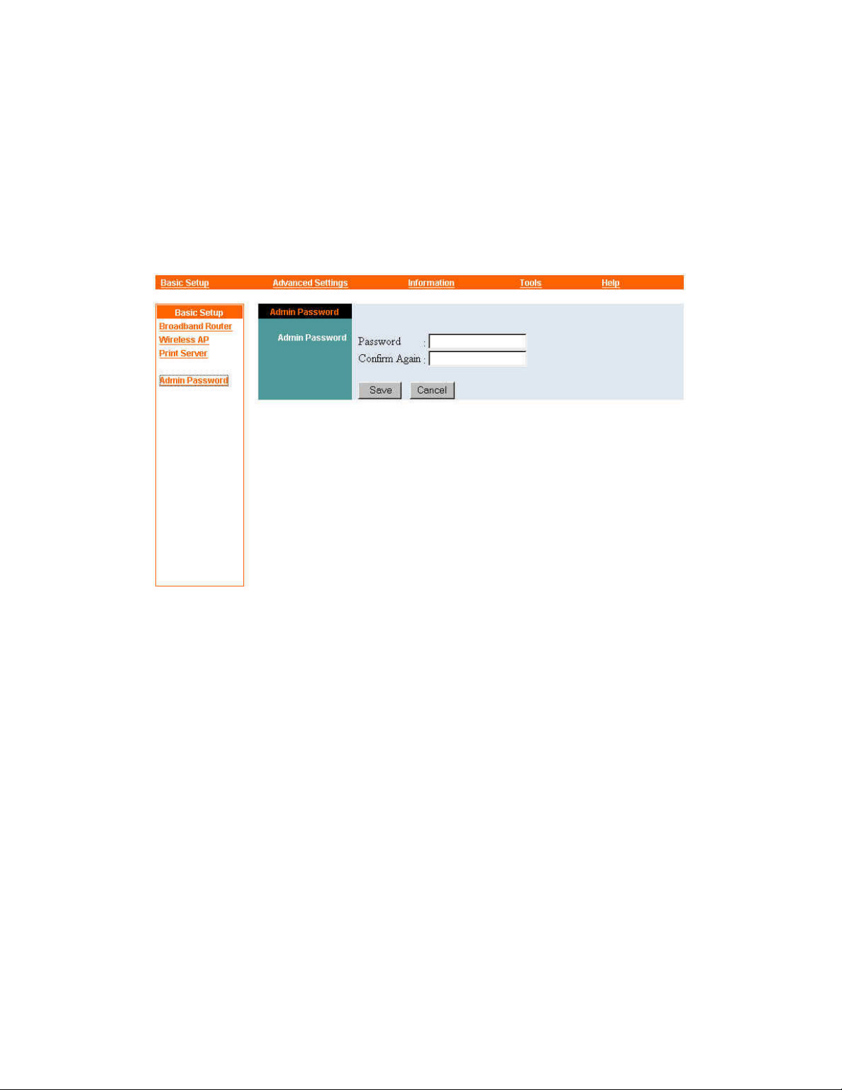
Basic Setup — Admin Password
It is highly recommended that you set an administrator password on the Wireless
Gateway as soon as possible to prevent any tampering with the device's settings. To
do this, click Admin Password in the command panel at the left edge of your browser
window (if the command does not appear there, click Basic Setup at the top of the
window first).
Set a password as follows:
1. Click in the Password box and type the desired password. The password
should not contain spaces, symbols, or punctuation marks. Note that only
asterisks will appear as you type.
2. Click in (or tab to) the Confirm Again box and type exactly the same string.
You can clear all input and start again, if you wish, by clicking the Cancel
button.
3. Click the Save button.
The password will be stored in the Wireless Gateway's non-volatile memory and take
effect immediately.
21
Page 22

Advanced Settings
Basic setup ensures that the Wireless Gateway will work with your ISP's equipment,
your wireless stations, and your printer. Further adjustments are usually necessary to
provide more sophisticated functions that may by desired or required on the local
network. Such adjustments are carried out through the settings panels under the
Advanced Settings menu. Those panels are:
• DHCP Server
• Port Forwarding
• Port Open
• Routing
• Filters
• Manager Console
• Wireless Access
• Wireless Encryption
• Wireless Bridge
22
Page 23

Advanced Settings — DHCP Server
The Wireless Gateway can act as a DHCP (Dynamic Host Configuration Protocol)
server for machines on your LAN. It is a way to use private addresses in t he LAN
when your ISP does not offer you enough globally legal IP addresses. This function is
turned on by default when the Wireless Gateway is first shipped or a factory reset is
carried out.
A DHCP server assigns IP addresses to stations on the LAN that are set up as DHCP
clients. See your operating system manuals for instructions on setting up stations as
DHCP clients. Each client will broadcast a request for configuration information upon
power-up. The server will then respond, providing an IP address and other TCP/IP
networking settings. You should not have more than one DHCP server on the LAN.
To view the Wireless Gateway's DHCP server settings, click DHCP Server in the
command panel at the left edge of your browser window (if the command does not
appear there, click Advanced Settings at the top of the window first). The DHCP
Server settings panel will appear. The controls in this panel are explained below.
23
Page 24
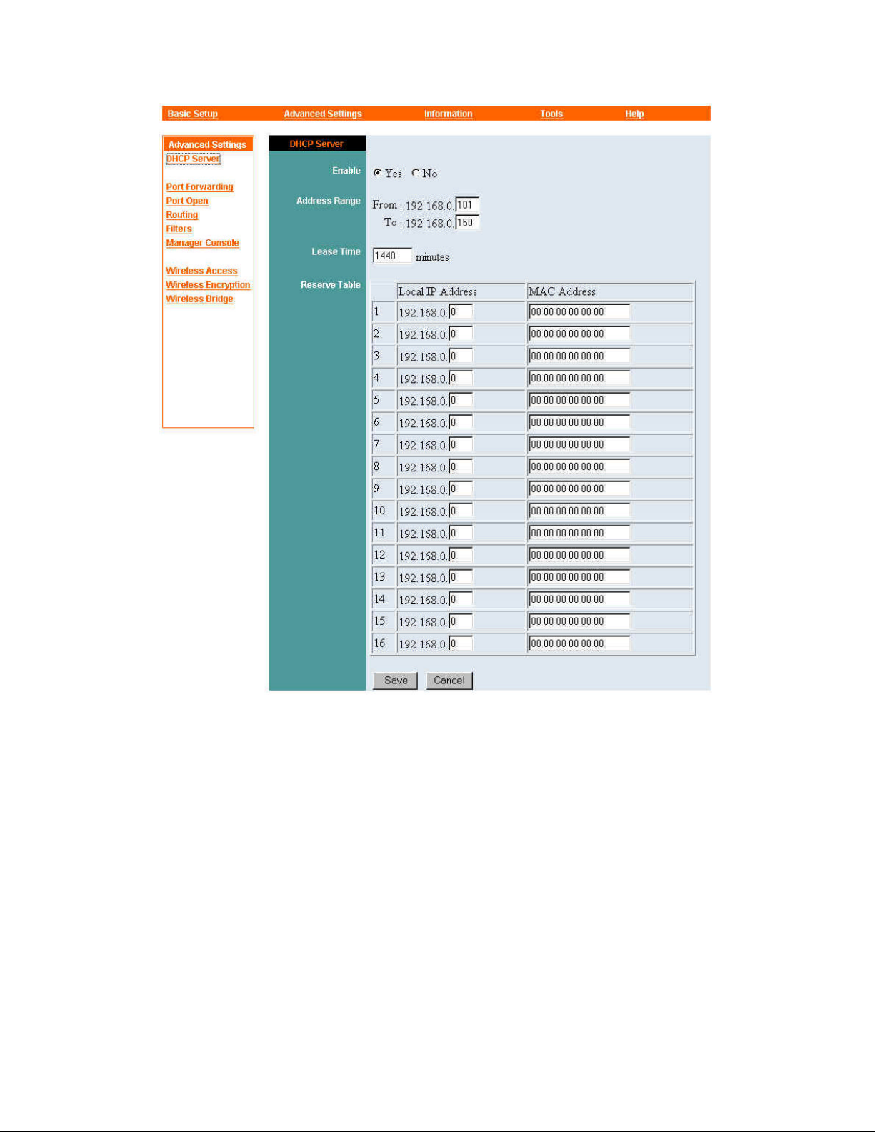
Enable
Click No to turn the Wireless Gateway's DHCP server function off, or click
to turn the function on. If you turn this function off, you can go directly to
Yes
the bottom of the panel and click Save, ignoring the rest of the controls in the
panel; they will have no effect on the Wireless Gateway's operation.
Address Range
The Address Range is the pool of addresses from which the Wireless Gateway
will assign addresses to DHCP clients on the LAN. The From control sets the
lowest address in this range, and the To control sets the highest. Be careful
24
Page 25

that the range of addresses must not contain the IP address you have already
given to the Wireless Gateway.
The From and To addresses always begin with the same three numbers as the
Wireless Gateway's Local LAN address (see “Broadband Router” under
“Basic Setup,” above). Only the last number of each address can be changed
through the DHCP Server settings panel. These two numbers are referred to
below as the “From value” and the “To value.”
The default From and To values are 101 and 150, respectively. These values
are suitable for the Wireless Gateway's default Local LAN settings or settings
similar to them — that is, settings that put the Wireless Gateway's LAN
interface on an undivided Class C IP network, where valid host addresses run
from x.x.x.1 to x.x.x.254. If the LAN interface is on a smaller network — that
is, if a Local LAN subnet mask other than 255.255.255.0 is chosen — and the
Wireless Gateway's DHCP server function is enabled, the DHCP address
range must be adjusted accordingly.
Lease Time
The Lease Time value is the number of minutes each DH CP client can use its
assigned IP address without requesting renewal from the Wireless Gateway.
The default setting is 1440 minutes (24 hours). If a DHCP client does not
request a lease renewal within this time, it is considered to have gone off the
network, and its IP address can be assigned to another client. Note that some
DHCP clients will themselves disconnect from the network if their lease time
runs out and the DHCP server is not available to renew the lease.
Reserve Table
The Reserve Table lets you make sure that when the DHCP server function is
enabled, the Wireless Gateway will always assign certain IP addresses to
certain DHCP clients and never to any others. This function is especially
useful when, for example, there’s a network print server which will be easier
to use with a fixed IP address in the LAN. The Reserve Table can contain up
to sixteen entries.
To reserve an IP address for a DHCP client, you must know the client
machine's MAC (Media Access Control) address. This is usually printed on a
label affixed to the machine or its network interface card, and consists of
25
Page 26

twelve hexadecimal digits with or without spaces in between. The
hexadecimal digits are 0 through 9 and A through F (in upper or lower case);
0080C82F8086, 0080c82f8086, 0080C8 2F8086, and 00 80 C8 2F 80 86 are
all different ways of writing the same MAC address.
To enter a MAC address in the Reserve Table, click in a table entry's MAC
Address box and type the address in, with or without spaces.
The first three numbers of the Local IP address are automatically set to those
of the Wireless Gateway's Local LAN address; for the fourth number, click in
the box provided and type a suitable value.
Save/Cancel
After making sure all settings in the DHCP Server panel are correct, click
Save to store the settings in the Wireless Gateway's non-volatile memory. You
can, alternatively, click Cancel (or simply exit the panel) to restore all settings
in the panel to the values last saved to or retrieved from the Wireless Gateway.
26
Page 27

Advanced Settings — Port Forwarding
A TCP “port” is a number associated with a protocol providing a specific service. The
source and destination port numbers are the first parts of a TCP packet.
Port forwarding is often used in conjunction with Network Address Translation
(NAT). When you use NAT, your LAN appears to the rest of the world to be a single
machine with the IP address of the Wireless Gateway's WAN port. Requests from
outside your LAN will all be directed to this address. Port forwarding is a means of
using TCP packets' destination port number to determine which machine on the LAN
each such request should be passed to.
In short, port forwarding lets you provide TCP -borne services such as FTP (the File
Transfer Protocol) and HTTP (the Hypertext Transfer Protocol of the World Wide
Web) to machines outside your LAN even if your servers' IP addresses are hidden
from those machines.
To view the Port Forwarding settings panel, click Port Forwarding in the command
panel at the left edge of your browser window (if the command does not appear there,
click Advanced Settings at the top of the window first). The Port Forwarding settings
panel will appear. The controls in this panel are explained below.
27
Page 28
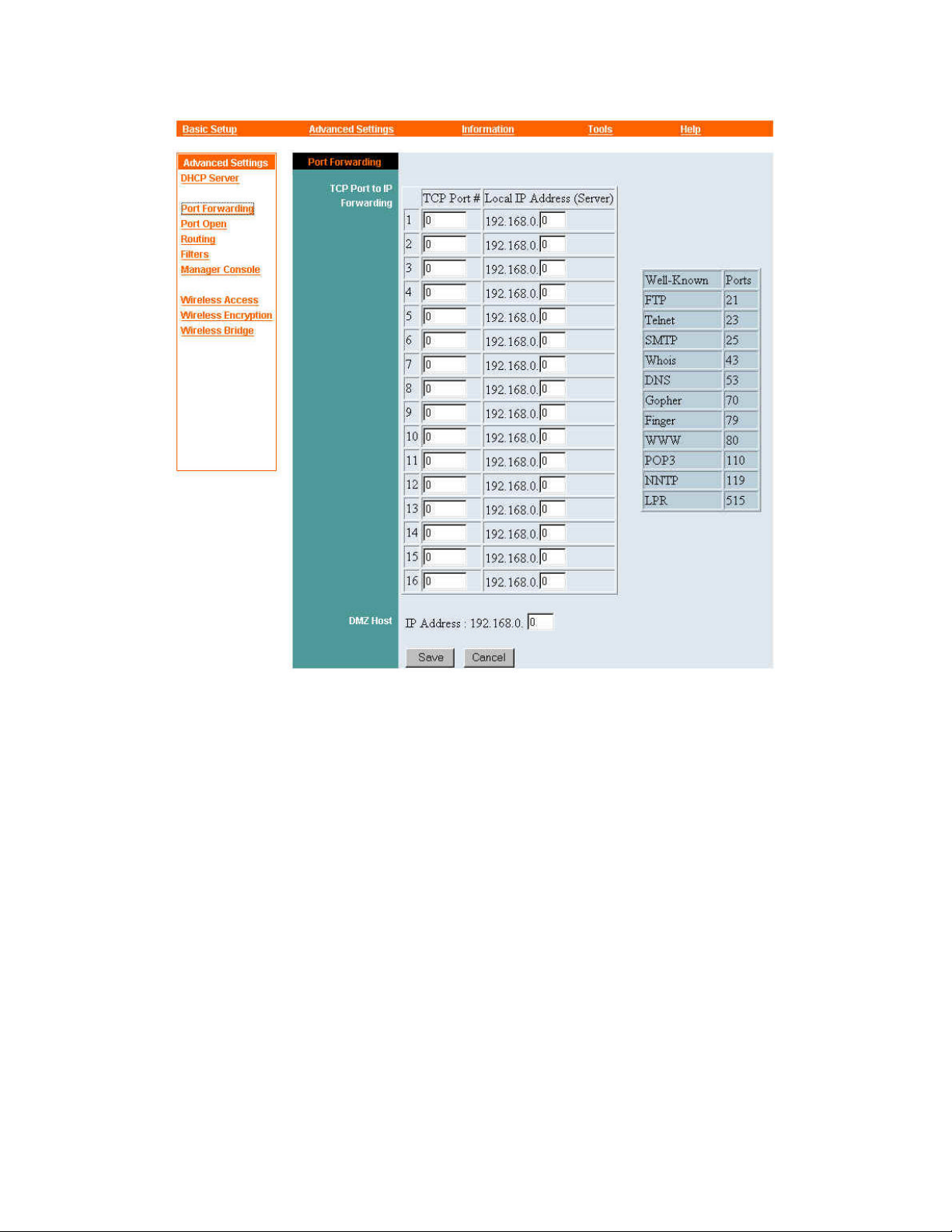
TCP Port to IP Forwarding
This is a table of up to sixteen entries. A list of standard, commonly used TCP
port numbers appears next to the table to help you create entries. Each entry
consists of
the port number for the protocol on which a particular
(1)
network-based service is based, and (2) the IP address of the server on your
LAN that will provide that service to machines outside the LAN.
To create an entry, fill in the TCP port number and type in the fourth number
of the local IP address associated with it (the first three numbers are
automatically set to those of the Wireless Gateway's Local LAN address; see
“Broadband Router” under “Basic Setup,” above).
To remove an entry, set the TCP port number or the local IP address, or both,
to zero.
28
Page 29

DMZ Host
A DMZ host is a machine exposed to the Internet and running software
designed to provide specific services while protecting the LAN's other
machines from direct access from outside. On the Wireless Gateway, if an IP
address for a DMZ host is specified, incoming packets of types not listed in
the TCP Port to IP Forwarding table will be directed to the DMZ host.
The first three numbers of the DMZ Host IP Address control are
automatically set to those of the Wireless Gateway's Local LAN address (see
“Broadband Router” under “Basic Setup,” above). The default value of the
fourth num ber is zero; this has the effect of disabling the Wireless Gateway's
DMZ Host function. If a DMZ host exists on the LAN, click in the box for the
fourth number and type the last number of that machine's IP address.
Save/Cancel
After making sure all settings in the Port Forwarding settings panel are correct,
click Save to store the settings in the Wireless Gateway's non-volatile memory.
You can, alternatively, click Cancel (or simply exit the panel) to restore all
settings in the panel to the values last saved to or retrieved from the Wireless
Gateway.
29
Page 30
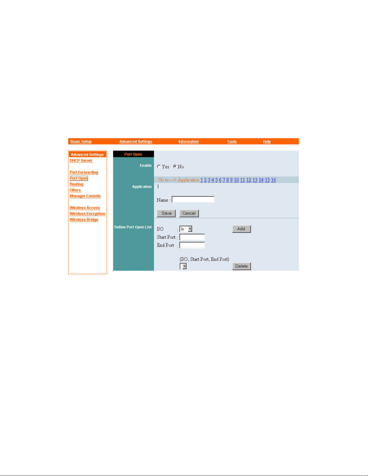
Advanced Settings — Port Open
The Port Open function is provided mainly to facilitate controlled Internet gaming. It
lets you specify the TCP ports that are used for input and output by up to sixteen
applications. When the function is enabled for application, the Wireless Gateway will
allow packets for the specified ports only (and none for any other ports) to pass
between the WAN and the machine on the LAN that started the packet exchange.
The controls in the Port Open settings panel are explained below.
Enable
You can turn the function on or off at any time by clicking the Enable control's
Yes or No button.
Go to
You can define Port Open settings for up to sixteen applications. The current
settings for application #1 are automatically displayed when the Port Open
panel first appears. To view or input settings for another application, click a
number here.
Application
30
Page 31

The Application section of the Port Open settings panel contains a number, a
Name input box, and Save and Cancel buttons.
The number is the number of the application for which Port Open settings
currently appear (see “Go to,” above).
The Name box helps you identify the application that the displayed settings
are for. To enter a name, click in this box and type any text up to 32 characters
long. Spaces and punctuation can be used. The name serves only as a reminder;
it does not affect operation in any way.
The Save and Cancel buttons work slightly differently from those in other
settings panels. They affect only the Enable setting and the contents of the
Name input box. Click Save to store these settings (but not those in the Define
Port Open List section of the panel) in the Wireless Gateway's non-volatile
memory; click Cancel to restore them to the values last saved to or retrieved
from the Wireless Gateway.
Define Port Open List
For the Port Open function to work, the Wireless Gateway must “know”
which port or ports an application uses for input from the WAN (and, in some
cases, output from the user's machine to the WAN). The Define Port Open List
section of the Port Open settings panel lets you list the port or ports an
application uses for input and output.
An application might use a single port for all input and output, or a different
port in each direction, or multiple ports (contiguous or non-contiguous) in one
direction or both. The Define Open Port List section of the Port Open settings
panel lets you input settings for all patterns of port use, from the simplest to
the most complex. The controls in this section are explained below.
The I/O control can be set to In or Out. This setting has no immediate effect.
Its effect comes when you click Add to store Start Port and End Port numbers
in the Wireless Gateway's non-volatile memory. If the I /O control is set to In,
the specified port or ports will be treated by the Wireless Gateway as input
ports; if it is set to Out, they will be treated as output ports.
The Start Port and End Port boxes are for specifying a port or a range of
ports. To specify a single port, click and type the same number into both boxes;
31
Page 32

to specify a range, click the Start Port box and type the lowest number of the
range, and then click in the End Port box and type the highest number.
The Add button is for sending the displayed I/O, Start Port, and End Port
settings to the Wireless Gateway for storage in non -volatile memory. Once an
entry has been added, it will appear in the drop-down list box titled (I/O, Start
Port, End Port). You can repeat the process as many times as necessary to
store complete port usage information for an application.
The
Delete
button is used in conjunction with the drop-down list box
(I/O,
Start Port, End Port) to remove port usage settings previously saved in the
non-volatile memory. (Note that in some browsers, the list box appears only
after I/O, Start Port, and End Port settings have been saved with the Add
button.) To delete an unwanted triplet of settings in
(I/O, Start Port, and End
Port), simply select those settings from the drop -down list a nd then click
Delete.
32
Page 33
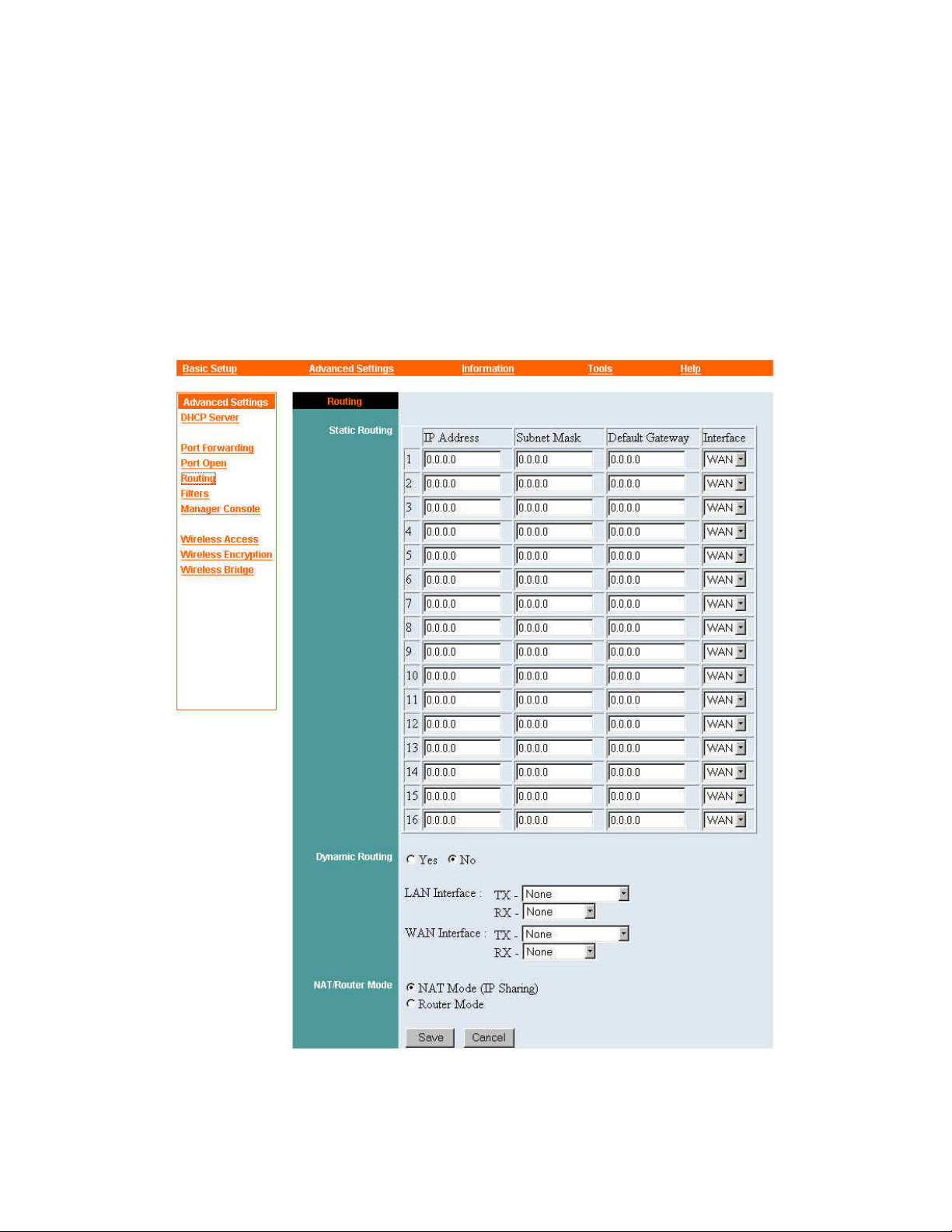
Advanced Settings — Routing
Routing settings determine whether the Wireless Gateway acts as a router, and how it
interacts with other routers for efficient dispatching of packets to other networks.
To view the Routing settings panel, click
Routing
in the command panel at the left
edge of your browser window (if the command does not appear there, click Advanced
Settings
at the top of the window first). The Routing settings panel will appear. The
controls in this panel are explained below.
Static Routing
33
Page 34

A static route is a known, unchanging path from your LAN to another network
or subnet. You can set up to sixteen static routes on the Wireless Gateway. A
static route consists of the settings described below.
IP Address: This is the IP network address of an outside network or subnet.
When a machine on your LAN addresses a packet to any machine on this
outside destination network, the Wireless Gateway will route that packet
according to your Static Routing settings.
Subnet Mask: A subnet mask is necessary for the above IP network address.
Default Gateway: This is the IP address of the router or other gateway that
can best handle packets addressed to the destination network or subnet. It must
be a device on your LAN or on the network that the WAN port is connected
to — that is, there must not be any intervening “hops” between the Wireless
Gateway and the default gateway.
Interface: The Interface control is a drop-down list box with two options:
WAN and LAN. If the default gateway (see prec eding) is networked to the
WAN port, leave this control set to its default setting, WAN; if the default
gateway is networked to one of the Wireless Gateway's LAN ports, set the
Interface control to LAN.
Dynamic Routing
The Wireless Gateway can perform dynamic routing — that is, it can
periodically exchange information with other routing devices to determine the
best paths for outward-bound packets. These exchanges are in a form called
the Routing Information Protocol (RIP). The Dynamic Routing section of t he
Routing settings panel lets you control RIP operation on the Wireless
Gateway.
The Yes and No options turn dynamic routing on and off, respectively. As a
general rule, if a simple point-to-point connection to an ISP through the WAN
port is the only link to networks other than the local LAN, dynamic routing
should probably be turned off; otherwise, it might need to be turned on. The
correct setting must be determined by a technician familiar with the
networking environment in which the Wireless Gateway is installed. If a
setting of No is chosen here, the remaining controls in the Dynamic Routing
section have no effect.
34
Page 35

The LAN Interface settings control whether and how the Wireless Gateway
uses RIP with any routing devices networked to it through its LAN ports.
• The TX setting controls the transmission of routing information to
such devices. Possible settings are None (send no RIP packets), RIP-1
(send RIP version 1 packets), RIP-1 Compatibility (send RIP version
1 packets, but internally support RIP version 2 functions), and RIP-2
(send RIP version 2 packets).
• The RX setting controls the handling of routing information received
from such devices. Possible settings are None (ignore all RIP packets),
RIP-1 only (accept only RIP version 1 packets), RIP-2 only (accept
only RIP version 2 packets), and RIP-1/RIP-2 (accept both kinds of
packets).
The WAN Interface settings control whether and how the Wireless Gateway
uses RIP with any routing devices networked to it through its WAN port. The
available TX and RX sett ings are the same as those for the LAN interface, and
their effects are the same except that they control RIP use through the WAN
port.
NAT/Router Mode
NAT stands for Network Address Translation. NAT is ordinarily used when
only the WAN port has a “globally legal” IP address and machines on the
LAN all use “private addresses.” In NAT operation, the Wireless Gateway
modifies outgoing packets so their source IP address is that of the Wireless
Gateway's WAN port. All machines on the LAN thus appear to be a single
machine to outside devices. The Wireless Gateway also makes other necessary
modifications of each outgoing packet, so that return packets can be directed
to the correct machines on the LAN. Since all machines on the LAN appear to
have the same IP address to outside devices, NAT operation is also known as
“IP sharing.”
NAT mode must be used when the machines on the LAN all use private
addresses. It can also be used as a partial firewall when the machines on the
LAN use globally legal IP addresses but no routing devices other than the
Wireless Gateway exist on the LAN.
Save/Cancel
35
Page 36

After making sure all settings in the Routing settings panel are correct, click
Save to store the settings in the Wireless Gateway's non-volatile memory. You
can, alternatively, click Cancel (or simply exit the panel) to restore all settings
in the panel to the values last saved to or retrieved from the Wireless Gateway.
36
Page 37
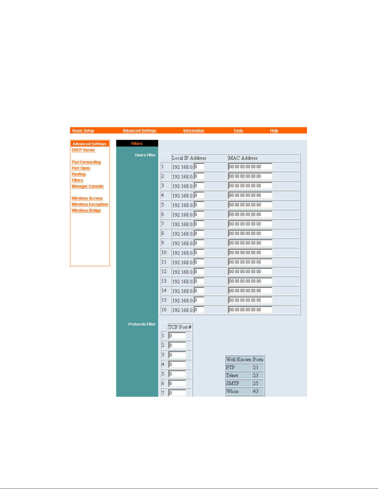
Advanced Settings — Filters
The Filters settings panel can be used to ensure that certain machines on the LAN
cannot access the WAN; to ensure that certain protocols cannot be used by anyone on
the LAN to access the WAN; to keep certain packets from triggering an on-demand
PPPoE connection; and to block all requests that originate on the WAN. The controls
in this panel are described below.
37
Page 38
Users Filter
The Users Filter table lists machines on the LAN that are not allowed to access
the WAN at all. There is room for sixteen entries. An entry can consist of an
IP address or a MAC address, or both. (If both are entered, the Wireless
Gateway will block all packets with either one, regardless of whether the other
is associated with it.)
The first three numbers of the Local IP Address control are automatically set
to those of the Wireless Gateway's Local LAN address (see “Broadband
Router” under “Basic Setup,” above). To enter a machine's IP address, click in
the box for the fourth number and type the appropriate number. Make sure the
machine you want to block always uses this IP address.
If a machine does not have a fixed IP address, WAN access from that machine
can still be blocked on the basis of the machine's MAC (Media Access Control)
address. This is usually printed on a label affixed to the machine or its network
interface card, and consists of twelve hexadecimal digits, possibly separated
by spaces. The hexadecimal digits are 0 through 9 and A through F (in upper
or lower case); 0080C82F8086, 0080c82f8086, 0080C8 2F8086, and 00 80 C8
2F 80 86 are all different ways of writing the same address. To enter a
machine's MAC address in the Users Filter table, find the address, click in a
table entry's MAC Address box and type the address in.
Protocols Filter
38
Page 39

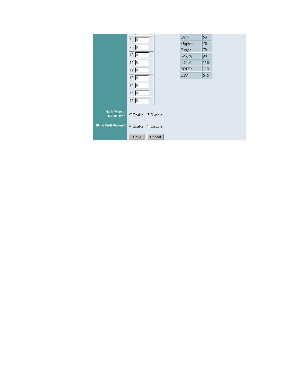
The Protocols Filter control lets you list the TCP port numbers for up to
sixteen protocols that you do not want LAN users to use over the WAN
connection. A list of standard, commonly used TCP port numbers appears next
to the table to help you create entries. To create an entry, simply click in a
TCP Port # box and type a port number.
NetBIOS over TCP/IP Filter
NetBIOS is a communication protocol designed for use on small networks and
heavily reliant on network-wide broadcasts. “NetBIOS over TCP/IP” (often
abbreviated as NBT) is a means of letting NetBIOS requests travel between
networks in TCP/IP packets. This method is used in Windows 95 and
Windows NT.
Since NetBIOS over TCP/IP can be routed between networks, it can trigger
dial-out on a dial-on-demand PPPoE WAN connection (see “Global WAN
Mode” under “Basic Setup — Broadband Router,” above). If you have a
PPPoE link to your ISP, and the Connect on Demand control is set to Yes,
you will almost certainly need to enable the NetBIOS over TCP/IP filter.
When the filter is enabled, NetBIOS over TCP/IP packets will not trigger
dialing and will not be passed from the LAN to the WAN link. (NetBIOS over
TCP/IP will still work among the machines on the LAN.)
If the Wireless Gateway's WAN port connects a LAN to a corporate network
containing resources that local machines must access using NetBIOS over
TCP/IP, the NetBIOS over TCP/IP Filter control should be set to Disable to
let those packets through.
Block WAN Request
The Block WAN Request function, if enabled, causes the Wireless Gateway to
ignore requests addressed to it from the WAN. This makes the Wireless
Gateway almost “invisible” to the outside world while still allowing access to
the WAN from the LAN.
Note that if the Block WAN Request function is enabled, outside machines
will not be able to “ping” the Wireless Gateway and remote management of
the Wireless Gateway will not be possible.
Save/Cancel
39
Page 40

After making sure all settings in the Filters settings panel are correct, click
Save to store the settings in the Wireless Gateway's non-volatile memory. You
can, alternatively, click Cancel (or simply exit the panel) to restore all settings
in the panel to the values last saved to or retrieved from the Wireless Gateway.
40
Page 41
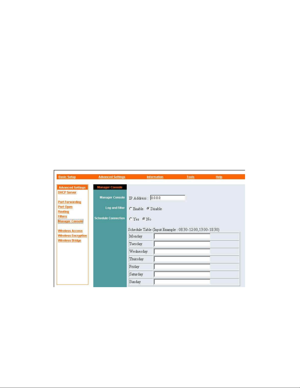
Advanced Settings — Manager Console
A “manager console” is a computer running Manager Server, a program designed to
enhance the capabilities of devices such as the Wireless Gateway and can be found in
the DC-ROM that comes with the Wireless Gateway. All the features in the Manager
Console panel require that such a computer be networked to the Wireless Gateway,
preferably through the wired LAN or the wireless access point. In addition, this
computer should be on and running Manager Server (which can run as a background
process) all the time to take full advantage of manager console features.
To set the Wireless Gateway up to work with a manager console, click Manager
Console
command does not appear there, click Advanced Settings at the top of the window
first). The controls in the Manager Console panel are explained below.
in the command panel at the left edge of your browser window (if the
41
Page 42
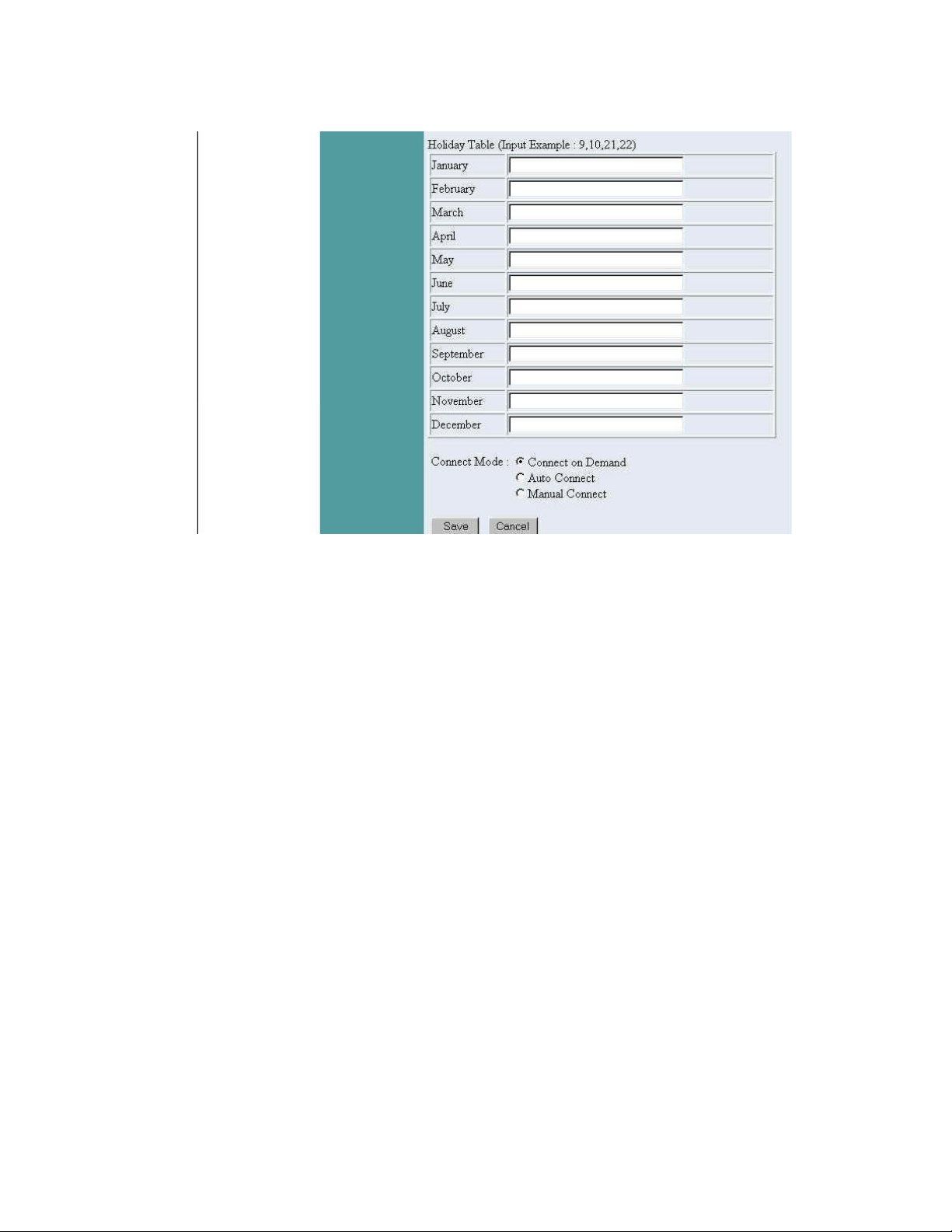
Manager Console
To communicate with a manager console, the Wireless Gateway must know
the manager console's IP address. If you have set up a manager console, click
in the IP Address box and type the address in.
If no manager console exists, make sure the manager console IP Address
control is set to 0.0.0.0 (this is the default setting). Any other setting will cause
the Wireless Gateway to attempt to contact the manager console at regular
intervals, adding unnecessarily to the network load.
A manager console can be networked to the Wireless Gateway through the
wired LAN, or the wireless access point. Since some manager console features
need quick response times to work well, however, it is best for any manager
console to be on the local LAN.
Log and Filter
The Wireless Gateway can send information about network activity to the
manager console. Manager Server can keep a log of this information; it can
also inspect the information as it is received and instruct the Wireless Gateway
42
Page 43

to filter (that is, bloc k) connections that meet criteria you set. For full details,
see the Manager Server user's guide.
The default setting of the Log and Filter control is Disable . This setting
ensures that the Wireless Gateway will not send information about network
activity to the manager console for logging or filtering. If you have set
Manager Server to log or filter connections made through the Wireless
Gateway, you must also set this panel's Log and Filter control to Enable for
the function to work.
Schedule Connection
The Schedule Connection section of the Manager Console panel consists of a
yes/no control, a schedule table, a holiday table, and a connect mode control.
Using these controls, you can —
• set exact times at which the Wireless Gateway should (or may) connect
to the WAN, and when it must disconnect, on each day of the week;
• specify days of the year on which the Wireless Gateway should not
connect to the WAN;
• specify whether connection (during times when it is allowed by the
tables) should be on-demand, continuous, or manually controlled;
• enable or disable the entire connection schedule.
For the Schedule Connection feature to work correctly, the manager console's
real-time clock must be set correctly, and the connection between the Wireless
Gateway and the manager console must be reliable.
The Yes/No control turns the Schedule Connection feature on and off. To use
this control, simply click Yes or No, and then click the Save button at the
bottom of the panel. Note that the Wireless Gateway will not connect to the
WAN at all if this feature is turned on and no connection times are specified in
the Schedule Table.
The Schedule Table is for specifying times when the Wireless Gateway can
or should connect to the WAN, and when it must disconnect, on each day of
the week. There can be multiple connection periods per day. An input example
above the table shows the correct format for each connection period: starting
time, hypen, ending time, where the times always contain four digits each, are
based on a 24-hour clock, and have a colon between the hour and the minute.
43
Page 44

Separate connection periods with commas; do not type any other characters,
not even spaces.
The Holiday Table is for specifying days of the year when the Wireless
Gateway should not connect to the WAN at all. Click in the input box for the
desired month and type the day or days of that month on which connection is
not allowed. Use only a comma, never a space, between days.
The Connect Mode control determines how connection to the WAN is
triggered when it is allowed by the schedule:
• Connect on Demand means to connect when someone on the LAN
tries to access the WAN;
• Auto Connect means to connect at the beginning of each specified
connection period, leave the connection open for the whole period, and
disconnect at th e specified ending time;
• Manual Connect means to connect only on command from the
manager.
Save/Cancel
After making sure all settings in the Manager Console settings panel are
correct, click Save to store the settings in the Wireless Gateway's non-volatile
memory. You can, alternatively, click
restore all settings in the panel to the values last saved to or retrieved from the
Wireless Gateway.
Cancel
(or simply exit the panel) to
44
Page 45
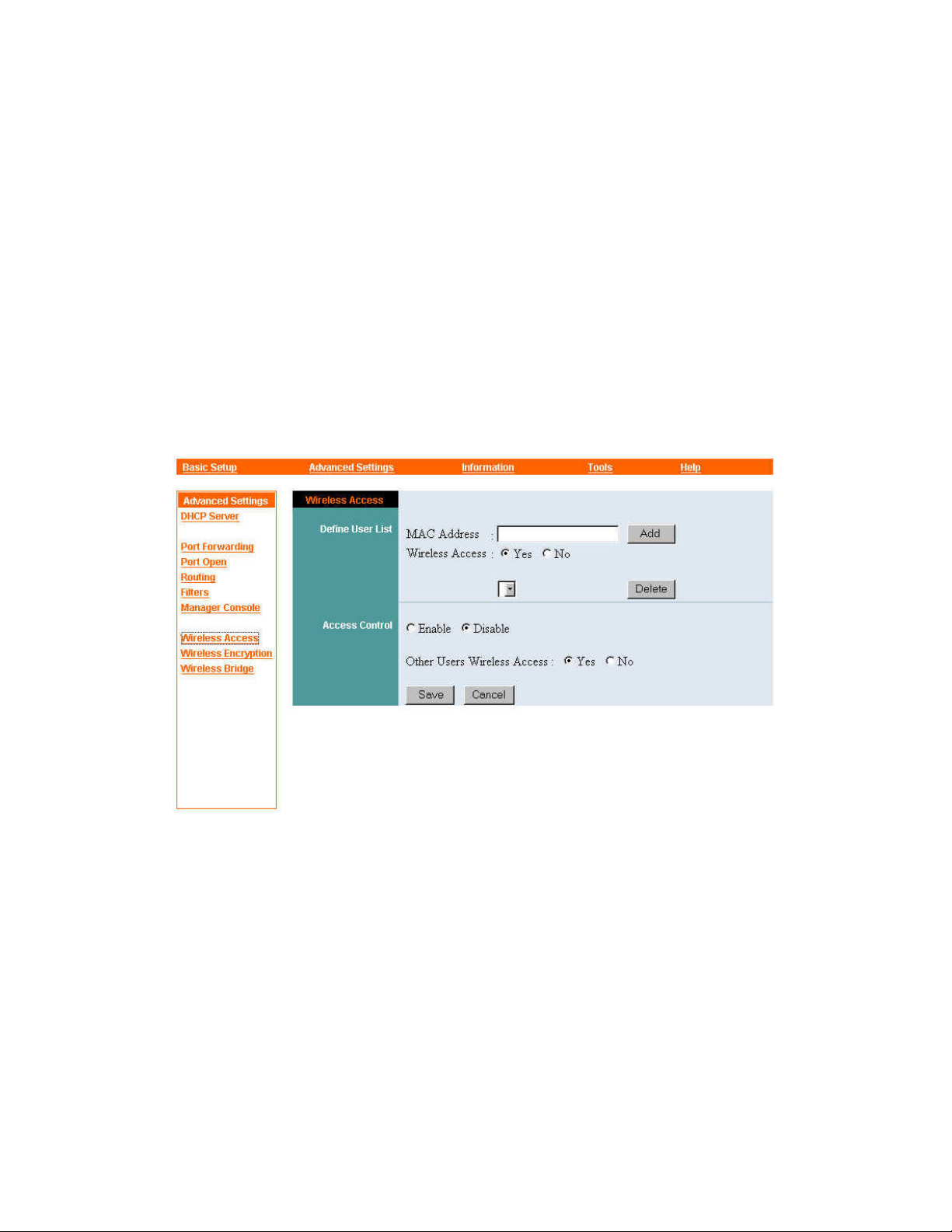
Advanced Settings — Wireless Access
The Wireless Access panel lets you contr ol which machines can, and which ones
cannot, connect to the network through the Wireless Gateway's wireless access point.
Initially, no controls are placed on wireless access through the Wireless Gateway. To
control access, you must create a “user list,” that is, a list of MAC (Media Access
Control) addresses, each with an indication of whether the station with that address is
allowed access or not. This list can then be enabled (that is, its restrictions put into
effect) or disabled. Finally, you must indicate whether stations not on the list are
allowed access or not.
The controls in the Wireless Access panel are explained below.
Define User List
The Define User List section of the Wireless Access panel contains controls
for creating and maintaining a list of wireless stations that are explicitly
allowed or denied wireless access to the network.
The MAC Address input box is for adding a station to the list. A station's
MAC address can usually be found on a label attached to the station's case or
its wireless interface card. It is a number in hexadecimal (base 16) notation,
and may contain the letters A through F (in upper or lower case) as well as the
digits 0 through 9. Spaces may be added for readability. An example of a
45
Page 46

MAC address is 0080C82F8086, which may also be written as 0080c82f8086,
0080C8 2F8086, or 00 80 C8 2F 80 86. The first step in creating a User List
entry is to click in the MAC Address input box and type the station's MAC
address, with or without spaces.
The Wireless Access control is for specifying whether the wireless station
with the specified MAC address will be allowed access or not. Click Yes to
allow access, No to deny it.
The
Add
settings in the Wireless Gateway's non-volatile memory.
The Delete button is used in conjunction with the drop-down list box next to it.
(Note that in some browsers, the list box appears only if there is at list one
entry in the User List.) These two controls are for removing entries from the
list. To remove an entry, open the list and click or drag to the unwanted entry;
then click Delete.
Access Control
The Access Control section of the Wireless Access panel turns the User List
on and off, and controls whether non-listed wireless stations are allowed
access or not.
The Enable/Disable control puts the User List into effect (“enables” it) or
causes it to be ignored (“disables” it). Click the appropriate setting.
The Other Users Wireless Access control determines whether unlisted
button stores the MAC Address and Wireless Access controls'
wireless stations will be allowed access or not. Clicking Yes allows them
access, clicking No denies it.
The
button stores the settings of the Enable/Disable and Other Users
Save
Wireless Access controls in the Wireless Gateway's non-volatile memory. The
settings take effect immediately after being saved.
46
Page 47
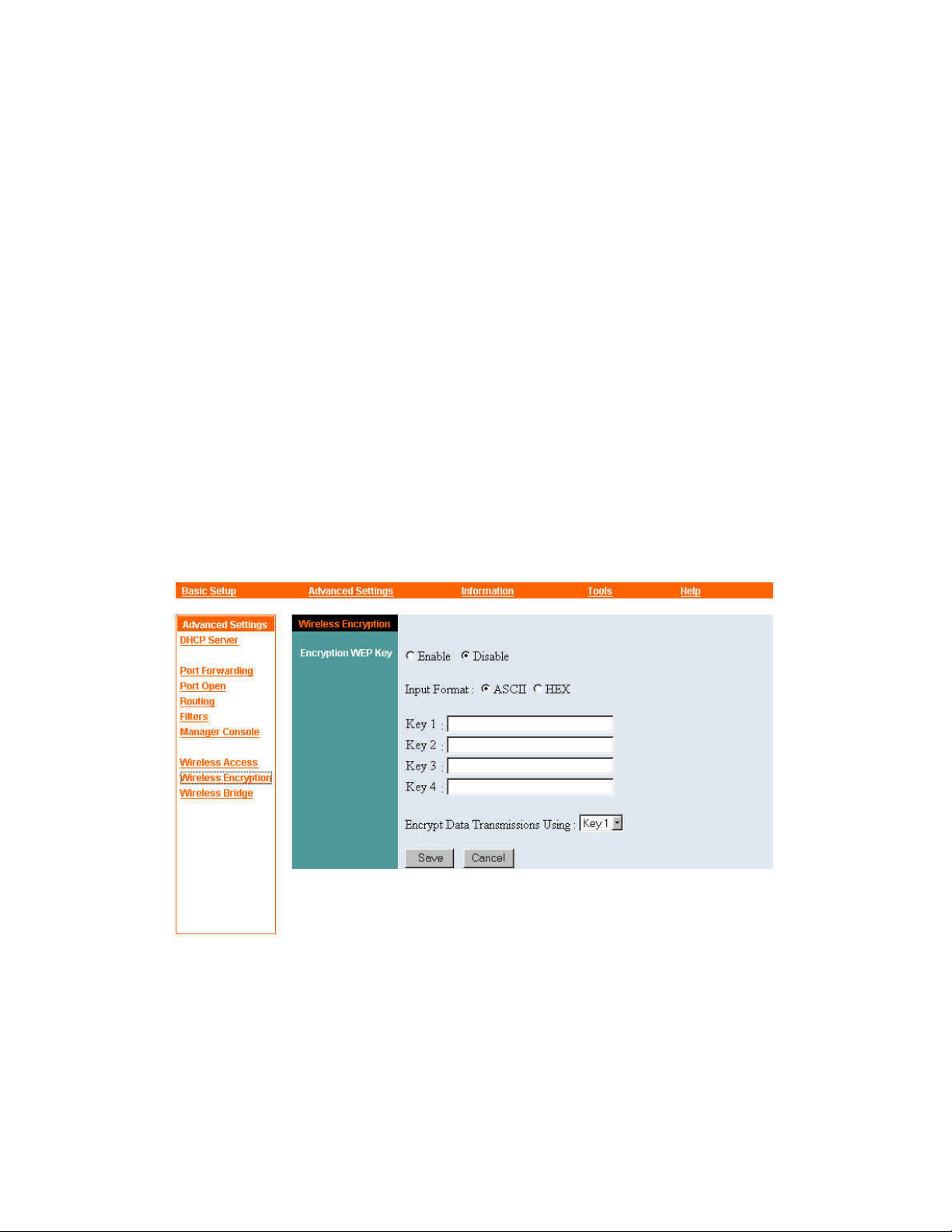
Advanced Settings — Wireless Encryption
Wireless network communications are easily intercepted. WEP (Wired Equivalent
Privacy) is an encryption method specified by the IEEE 802.11b standard to make any
intercepted communications extremely difficult to interpret by unauthorized parties.
The Wireless Gateway supports WEP with up to four “keys,” as specified in the
standard. Each key can be of the 64-bit type or the 128 -bit type.
When WEP encryption is enabled on the Wireless Gateway, wireless access will be
granted only to stations that also use WEP encryption with the same key as the
Wireless Gateway.
The recommended way to use WEP is as follows: (1) Decide on an input format and
create four keys (key creation is explained below). (2) Select the key to be used (this
must be done on the Wireless Gateway and all wireless stations communicating
through it). (3) Enable WEP encryption.
The controls in the Wireless Encryption panel are explained below.
Enable/Disable
The Enable/Disable control turns WEP encryption on and off on the Wireless
Gateway. Click the desired setting. Any change in the setting takes effect
when the settings in the Wireless Encryption panel are saved. For other
47
Page 48

wireless devices to communicate through the Wireless Gateway, their
encryption settings must be the same as the Wireless Gateway's.
Input Format
The Input Format control determines how your input for Key 1 through Key 4
will be interpreted by the Wireless Gateway when you save the settings in the
Wireless Encryption panel.
Although your keys can be different lengths (that is, some can be 64-bit and
some 128-bit), you must use the same input format (ASCII or hex) for all four
keys.
ASCII format causes each character you type to be interpreted as an eight-bit
value. All unaccented upper- and lower -case Western European characters that
can be input through your keyboard's typing zone are valid. For a 64-bit key,
you must type 5 characters; for a 128-bit key, you must type 13 characters.
These character counts result in bit counts of 40 and 104, respectively; the
Wireless Gateway will automatically pad your input to a bit count of 64 or
128.
Hex format
causes each pair of characters you type to be interpreted as an
eight-bit value in hexadecimal (base 16) notation. Only the digits 0 through 9
and the letters A through F (in upper or lower case) are valid. For a 64-bit key,
you must type 10 pairs of characters; for a 128-bit key, you must type 26 pairs
of characters. These character counts result in bit cou nts of 40 and 104,
respectively; the Wireless Gateway will automatically pad your input to a bit
count of 64 or 128.
Key 1 through Key 4
After deciding on an input format (see preceding), click in each key input box
and type the key you have decided to use. To help maintain security, only
asterisks will appear as you type. Remember to input the same keys on stations
that will need to communicate through the Wireless Gateway's wireless access
point.
Encrypt Data Transmissions Using
48
Page 49

This control determines which key the Wireless Gateway will use when WEP
encryption is enabled. Click the list box to open it, and then drag to or click
the name of the desired key.
For good security, it is advisable to switch keys often. Remember to switch to
the same key on both the Wireless Gateway and all wireless stations that need
to communicate through it.
Save/Cancel
After making sure all settings in the Wireless Encryption settings panel are
correct, click Save to store the settings in the Wireless Gateway's non-volatile
memory. You can, alternatively, click Cancel (or simply exit the panel) to
restore all settings in the panel to the values last saved to or retrieved from the
Wireless Gateway.
49
Page 50
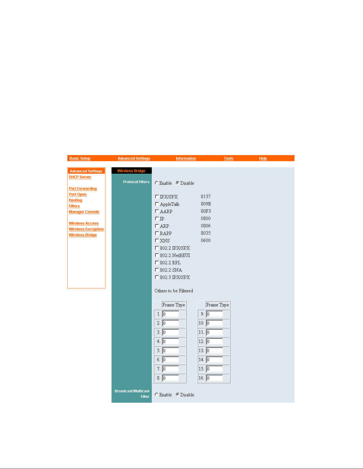
Advanced Settings — Wireless Bridge
The “wireless bridge” is the circuitry tha t transfers packets between the wireless
access point and wired connections. The purpose of the Wireless Bridge settings panel
is to prevent specified kinds of packets from passing across this bridge. This may be
done to increase network security or to avo id congestion on the wireless segment.
To access the Wireless Bridge panel, click
Wireless Bridge
in the command panel at
the left edge of your browser window (if the command does not appear there, click
Advanced Settings
at the top of the window first). T he controls in the Wireless
Bridge panel are explained below.
50
Page 51
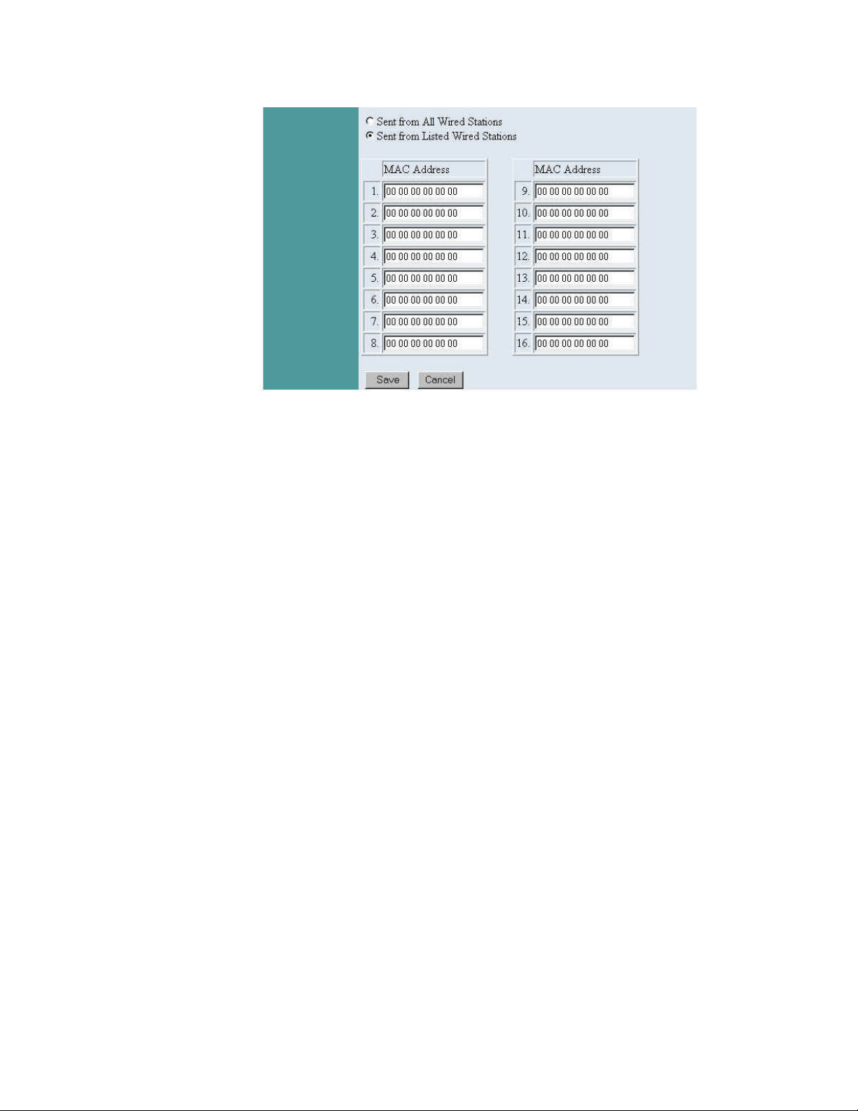
Protocol Filters
Protocol filters prevent specified kinds of packets from passing in either
direction across the wireless bridge. The Protocol Filters section of the
Wireless Bridge panel contains controls for turning this function on and off
and for selecting the filter or filters you want to use.
The Enable/Disable control is for turning the protocol filters that you have
selected on and off. The default setting of this control is Disable , that is, any
selected filters are off and no protocols are blocked.
Common protocols are listed below the Enable/Disable control. (Numbers in
hexadecimal notation appear to the right of several protocols. These are
“protocol IDs,” for reference only.) To select or deselect a protocol, click the
check box next to it. When a protocol is selected and the Enable/Disable
control is set to Enable, that protocol will be filtered, that is, prevented from
passing in either direction across the wireless bridge.
The “Others to be Filtered” section lets you select protocols not listed by name.
To select such a protocol, you must know its protocol ID (also known as the
“Ethernet type,” “type element,” or “length element” code). To select a
protocol in this way, click in a
Frame Type
ID.
Broadcast/Multicast Filter
51
input box and type the protocol
Page 52

Unlike protocol filters, the Broadcast/Multicast Filter function is one-way: it
prevents broadcast packets (those addressed to all stations on the network) and
multicast packets (those addressed to two or more, but not all, stations) from
passing through the wireless bridge from the wired segment to the wireless
segment.
Because of its (usually) lower speed and higher overhead, the wireless
segment can become congested more easily than the wired segment. You can
use the Broadcast/Multicast Filter function to reduce the possibility of
congestion on the wireless segment. You can keep the wireless segment free
of broadcasts and multicasts from all wired stations or from specified wired
stations only.
Broadcast packets are most often sent out in search of a server. The most
common use of multicast packets is to deliver streaming audio and video. It is
recommended that you use the Broadcast/Multicast Filter function only if your
servers are all on the wired segment and you do not need to deliver streaming
audio and video to wireless stations.
The Enable/Disable control turns the Broadcast/Multicast Filter function on
and off. The default setting is Disable , that is, the function is off, and
broadcast and multicast packets can pass freely from the wired segment to the
wireless segment.
If Sent from All Wired Stations is selected and the Broadcast/Multicast
Filter function is enabled, no broadcast or multicast packets from any wired
station will be allowed onto the wireless segment.
The Sent from Listed Wired Stations option lets you specify that only
broadcast and multicast packets from particular wired stations are to be
blocked at the wireless bridge.
The MAC Address input boxes are for listing the wired stations from which
broadcast and multicast packets should be blocked at the wireless bridge. You
can list up to sixteen machines. A station's MAC address can usually be found
on a label attached to the station's case or its network interface card. It is a
number in hexadecimal (base 16) notation, and may contain the letters A
through F (in upper or lower case) as well as the digits 0 through 9. Spaces
may be added for readability. An example of a MAC address is
0080C82F8086, which may also be written as 0080c82f8086, 0080C8 2F8086,
52
Page 53

or 00 80 C8 2F 80 86. To list a station, find its MAC address, click in a MAC
Address box, and type the address, with or without spaces.
Save/Cancel
After making sure all the controls in the Wireless Bridge settings panel are set
as desired, click Save to store the settings in the Wireless Gateway's
non-volatile memory. You can, alternatively, click
panel) to restore all settings in the panel to the values last saved to or retrieved
from the Wireless Gateway.
Cancel
(or simply exit the
53
Page 54

Information
The Information menu contains commands for displaying information about the
Wireless Gateway and network activity. Those commands are:
• Device
• DHCP
• Routing
• Users
• Connections
• WAN Link
• Printer Status
• Wireless Stations
• Wireless Tallies
Some or all of the information displayed by each of these commands can change at
any time. Each information panel contains a Refresh button that you can click to get
the latest information from the Wireless Gateway.
The information panels displayed by these commands are explained below.
54
Page 55
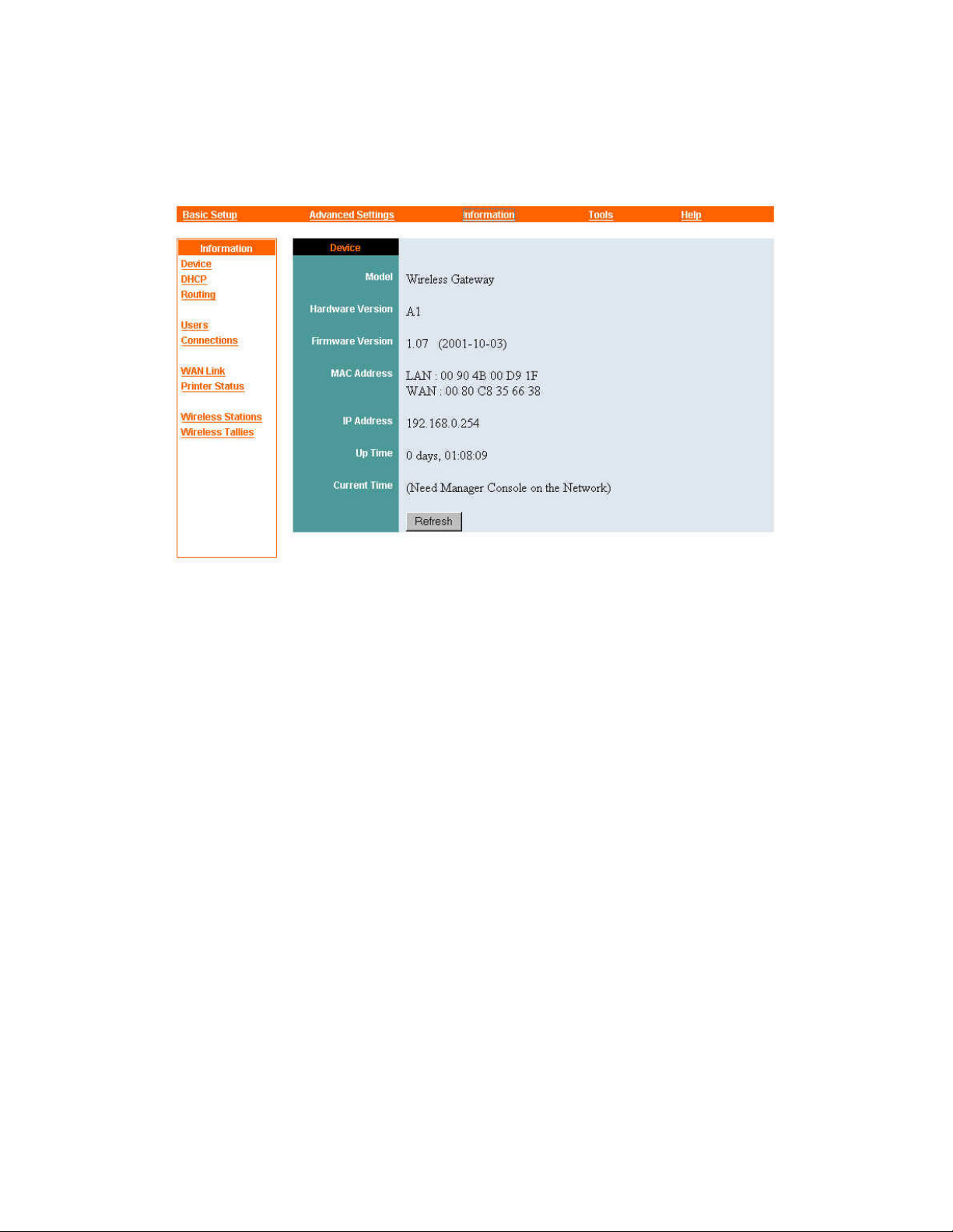
Information — Device
The Device information panel shows information about the Wireless Gateway itself.
Information shown at the top of the panel is fixed: Model, Hardware Version (version
number of the unit's physical circuitry), and Firmware Version (version number of the
code in the unit's read-only memory).
The unit's MAC addresses are shown in the middle of the panel. The MAC address
used on the LAN cannot be changed; the MAC address of the WAN port is fixed
unless changed through the Basic Setup menu's Broadband Router panel.
The IP address used by the Wireless Gateway on the LAN is also fixed unless
changed through the Basic Setup menu's Broadband Router panel.
Up Time is the amount of time that has passed since the Wireless Gateway was last
turned on. This item changes each time you refresh the display.
Current Time works only if a manager console, that is, a computer running Manager
Server, is running on the network and the Wireless Gateway is set up to work with it.
See “Advanced Settings — Manager Console,” earlier in this guide, for details.
55
Page 56
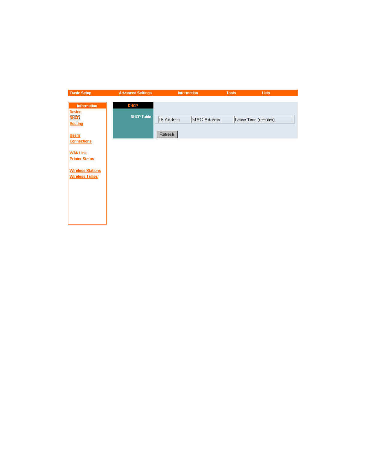
Information — DHCP
Click DHCP in the command panel at the left edge of your browser window to
monitor the operation of the Wireless Gateway's DHCP server function.
The DHCP information panel shows the IP addresses that the Wireless Gateway has
assigned to machines on the LAN. Next to each IP address is the MAC address of the
machine to which the address is assigned. A third column labeled “Lease Time
(minutes)” shows the amount of time remaining before the machine's lease on the IP
address expires. See “Advanced Settings — DHCP Server,” earlier in this guide, for
details.
56
Page 57
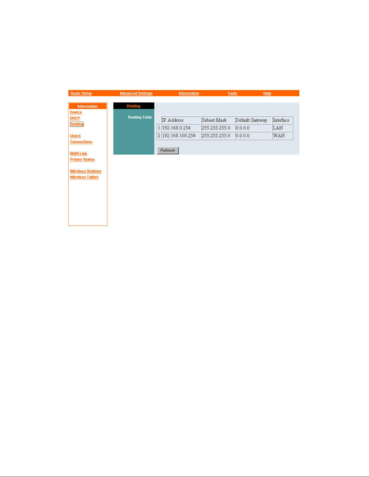
Information — Routing
The Routing information panel shows information about the Wireless Gateway's ports
and known routes, both learned and static, to other networks or subnets.
A learned or static route consists of a network address and subnet mask, the IP
address of the gateway to that network, and the Wireless Gateway interface (LAN or
WAN) thr ough which that gateway can be reached.
57
Page 58
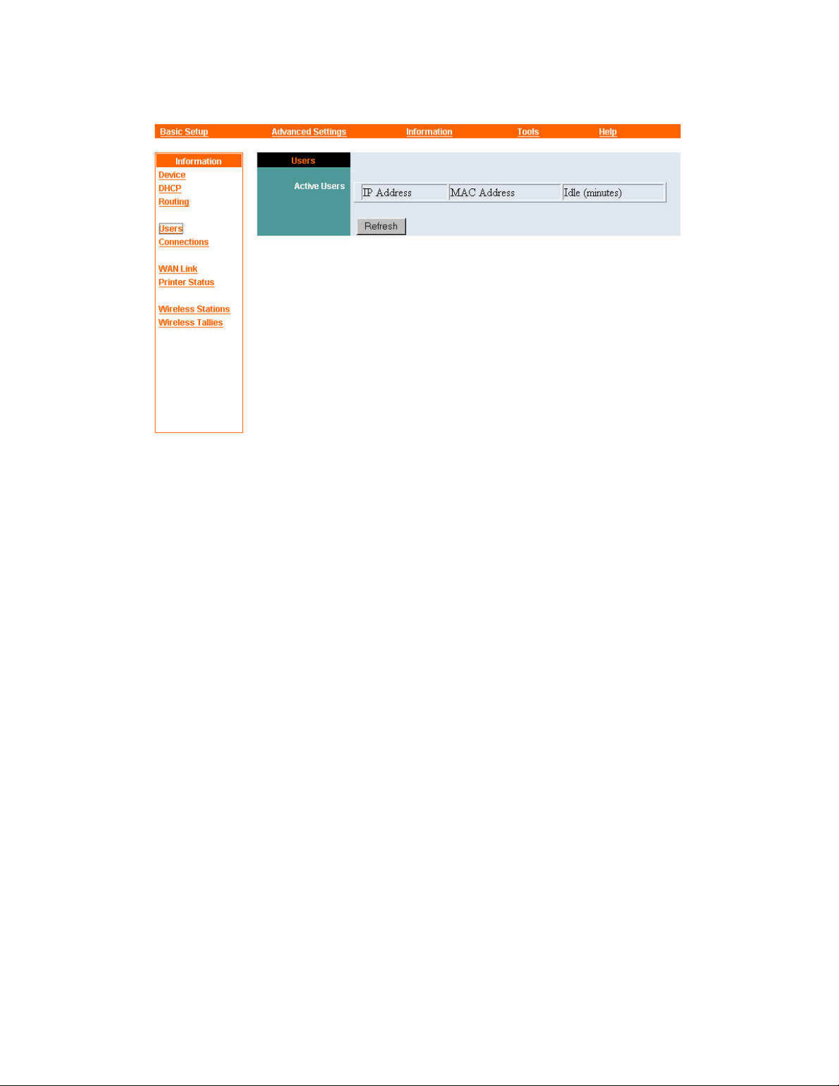
Information — Users
The Users information panel identifies machines on the LAN that have currently
active connections to the Internet. For each machine with an active connection, it
shows the IP address, MAC address, and the number of minutes since the last packet
transfer through the Wireless Gateway.
58
Page 59
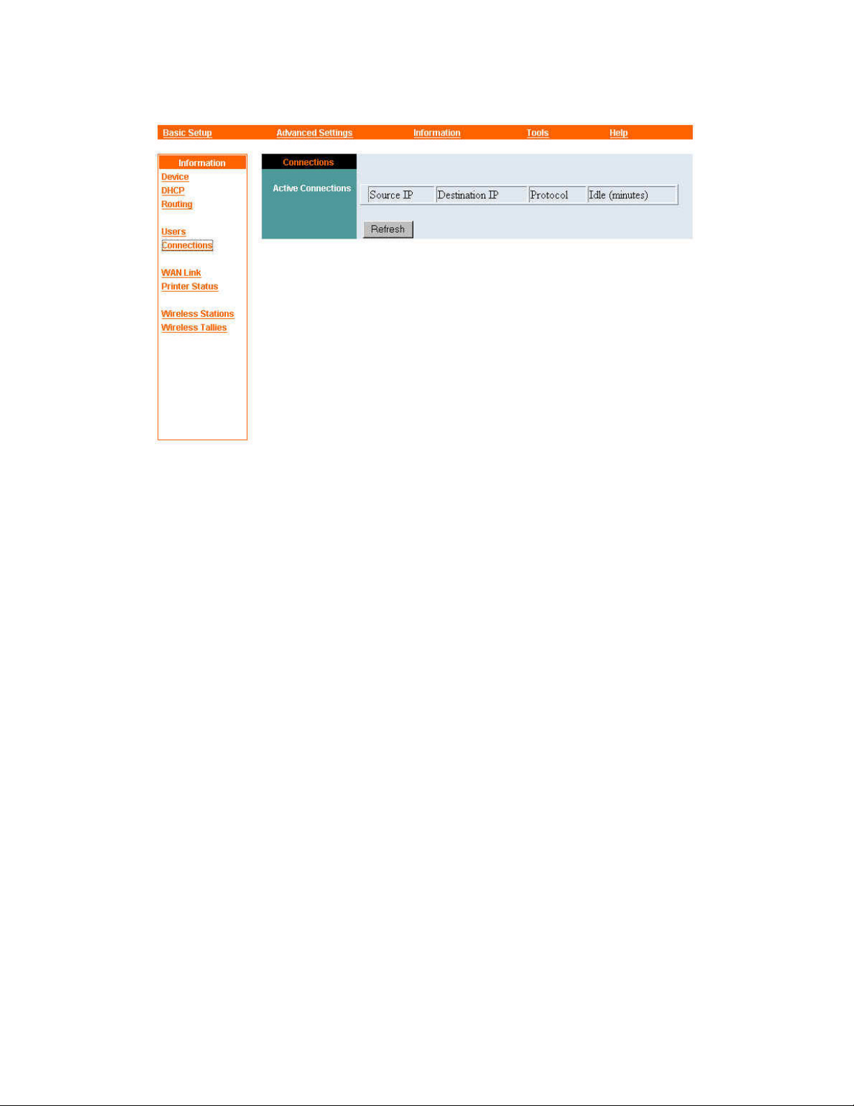
Information — Connections
The Connections information panel gives details of connections between the LAN and
the Internet. The source and destination IP addresses identify the machines at the two
ends of the connection; the protocol identifies the application being used; and the
“Idle (minutes)” column shows how long it has been since the last packet was
transferred.
59
Page 60
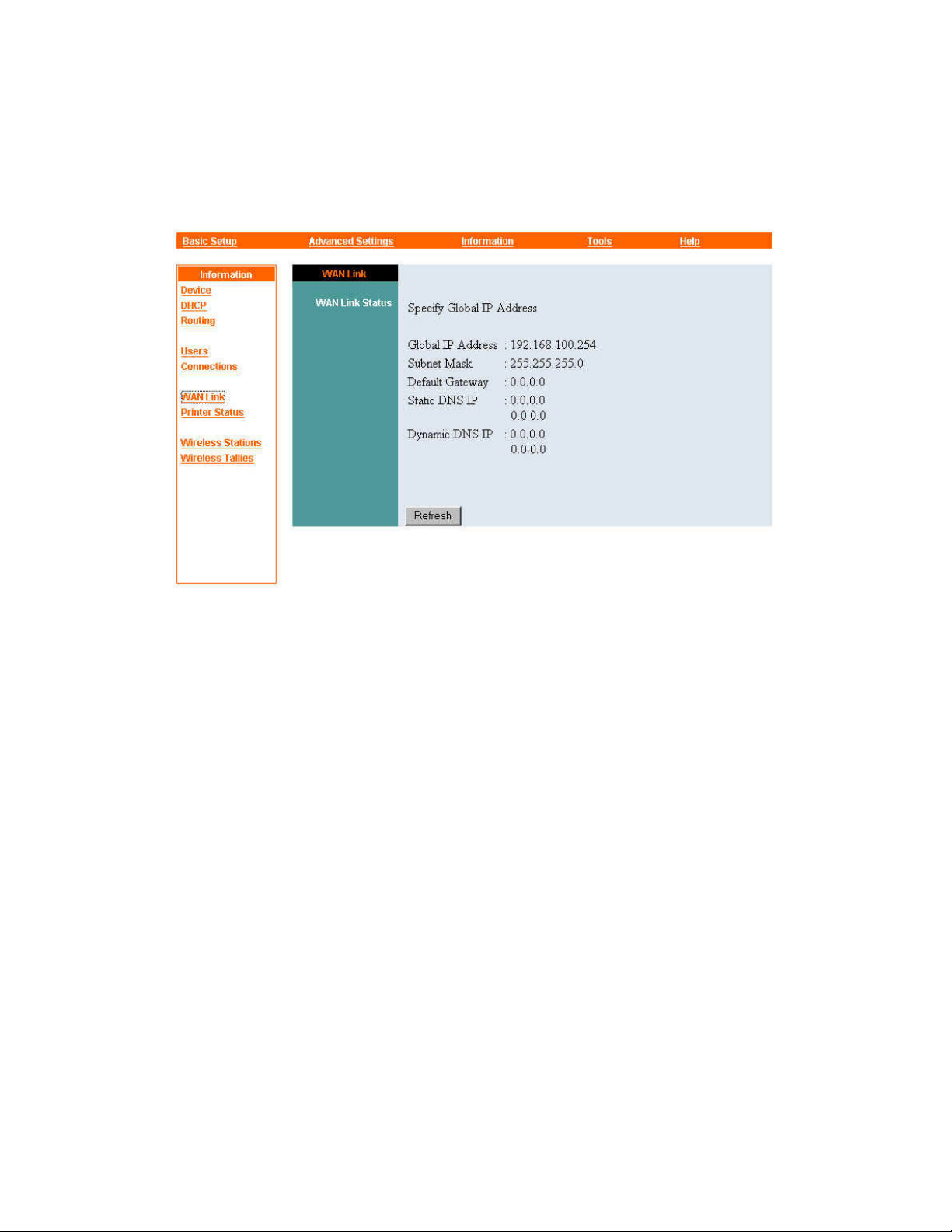
Information — WAN Link
The Information menu's WAN Link command displays the status of the Wireless
Gateway's WAN port.
Basic status can be “Specify Global IP Address,” “Obtain Global IP Address
Automatically (DHCP),” or “PPP over Ethernet (PPPoE),” depending on which of
these is currently selected in the Basic Setup menu's Broadband Router settings panel.
When basic status is “Specify Global IP Address,” this panel shows settings input by
the user in the Basic Setup menu's Broadband Router panel (and also viewable there).
When basic status is “Obtain Global IP Address Automatically (DHCP)” or “PPP
over Ethernet (PPPoE),” this panel shows the WAN port settings received from the
ISP over the WAN link. Any static DNS server IP addresses input by the user in the
Basic Setup menu's Broadband Router panel are also shown.
60
Page 61
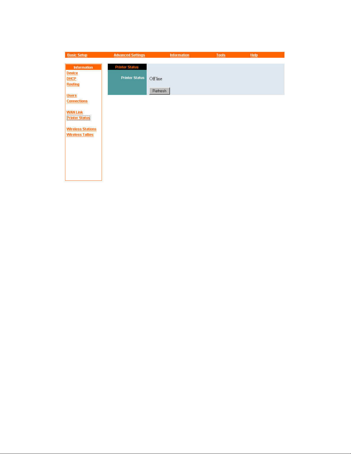
Information — Printer Status
The Printer Status panel shows whether a connection to a printer can be detected on
the Wireless Gateway's printer port. If the connection to the printer is good and the
printer is on, printer status will be given as “On line”; otherwise it will be given as
“Off line.”
61
Page 62
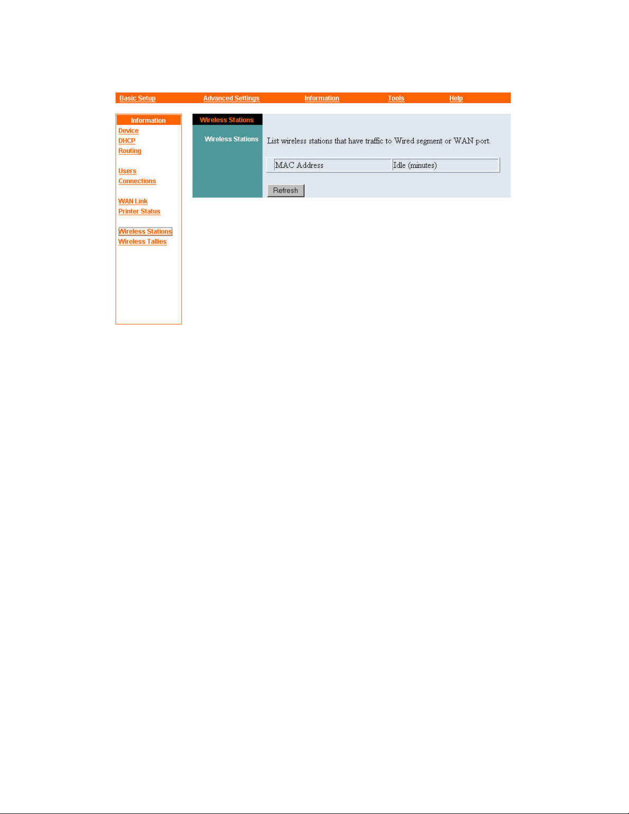
Information — Wireless Stations
The Wireless Stations panel displays the MAC addresses of wireless stations that have
sent packets to the wired segment or the WAN port. The amount of time since the last
wireless-to-wired communication is also shown.
Click Refresh to add any wireless stations that began sending packets to the wired
segment or the WAN since the Wireless Stations panel appeared.
62
Page 63
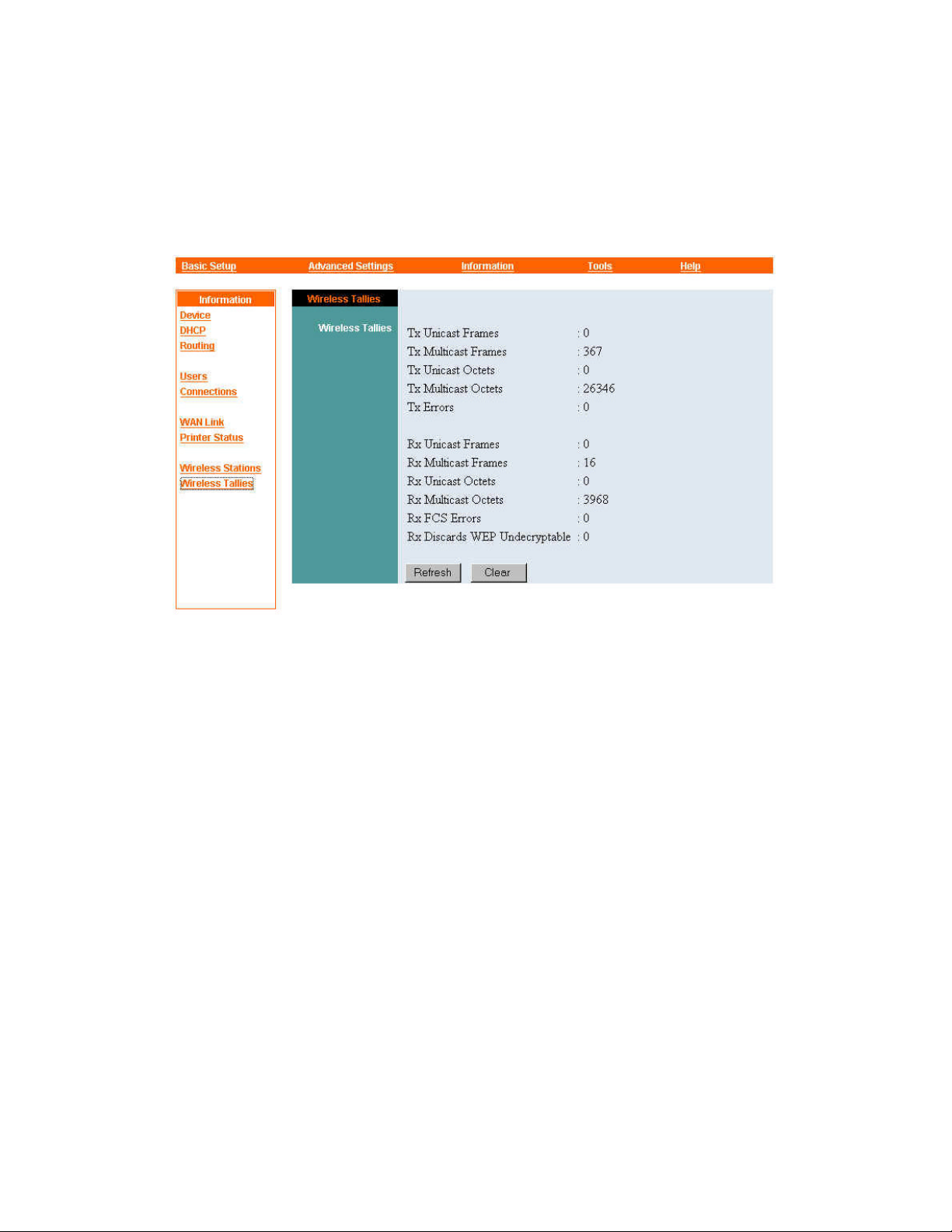
Information — Wireless Tallies
The Wireless Tallies panel gives statistics on the operation of the Wireless Gateway's
wireless access point. These statistics help you check wireless activity levels and
monitor the health of the wireless segment.
Figures are given for several kinds of transmitted (Tx) and received (Rx) frames.
(“Frame,” in this context, can be interpreted to mean “packet”).
Unicast frames are packets addressed to a single machine.
Multicast frames are packets addressed to more than one machine. Packets addressed
to all machines on the network, often called broadcast packets, are included in these
tallies.
Tx Errors is the number of packets transmitted erroneously.
Rx FCS Errors is the number of packets received from wireless stations and found to
have Frame Check Sequence errors. The FCS is a value computed by the sender on
the basis of packet contents and then sent at the end of the packet. The Wireless
Gateway does the same calculation and compares the result with the value received. A
packet with an FCS error is silently dropped; the sender, receiving no
acknowledgement, automatically tries again. An abnormally large number of FCS
errors usually indicates radio-frequency interference or a faulty transmitter.
63
Page 64

Rx Discards WEP Undecryptable is the number of packets dropped because the
sender's WEP encryption settings differed from the Wireless Gateway's. Packets will
be dropped if the devices use different keys or one device uses encryption and the
other does not.
Click Refresh at any time to retrieve the most recent wireless tallies from the
Wireless Gateway.
64
Page 65
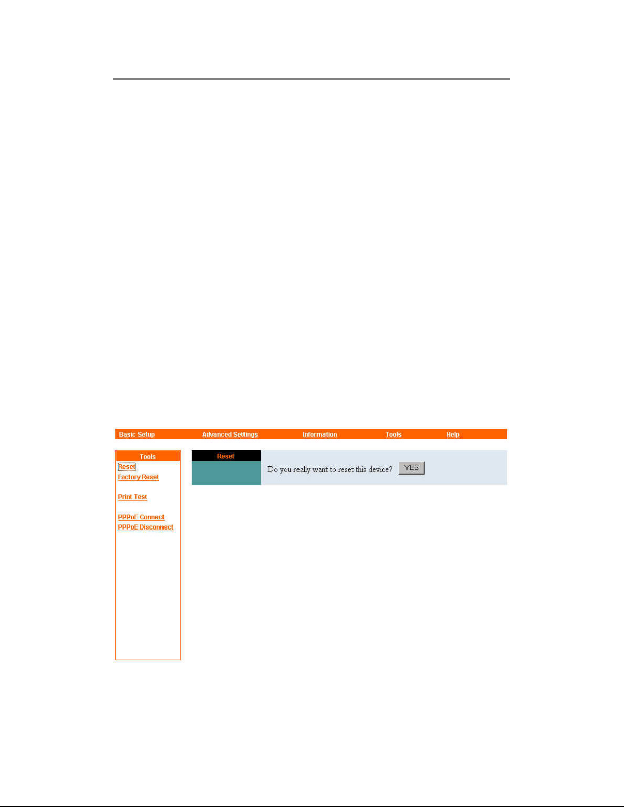
Tools
The Tools menu contains commands for restarting the Wireless Gateway, testing the
printer connection, and controlling a PPPoE (Point-to-Point over Ethernet) WAN link.
The names of these commands are —
• Reset
• Factory Reset
• Print Test
• PPPoE Connect
• PPPoE Disconnect
Only the PPPoE Connect and PPPoE Disconnect commands are carried out
immediately when you click the name in the command panel at the left edge of your
browser window. For the Reset, Factory Reset, and Print Test commands, a button
appears to let you confirm the command before it is carried out.
Further details on these commands are given below.
Tools — Reset
65
Page 66

The Reset command restarts the Wireless Gateway just like turning the device off and
on. Saved settings are retained, but tally counters are restarted from zero after the
reset. The Reset panel contains the message “Do you really want to reset this device?”
and a YES button. If you do not want to reset the Wireless Gateway, exit the panel
without clicking YES; otherwise, click YES and the reset process will begin.
Tools — Factory Reset
A factory reset restarts the Wireless Gateway and returns all of its settings to their
default values. The Factory Reset panel contains the message “Do you really want to
factory reset this device?” and a YES button. If you do not want to carry out a factory
reset, exit the panel without clicking
process will begin.
Note: The Wireless Gateway must be reconfigured after a factory
reset.
; otherwise, click
YES
and the factory reset
YES
Tools — Print Test
The Print Test command lets you test an attached printer and the connection to it. The
Print Test panel contains a Port Selection control and a Test button. The Port
Selection
Gateway's printer port.
To test the printer and the connection to it, click the Test button. If a connection to a
printer can be detected, the message “LPT: On line” will appear and a Test Page will
be printed out to the printer; otherwise, “LPT: Off line” will be displayed.
control is permanently set to
, the internal name for the Wireless
LPT
Tools — PPPoE Connect and PPPoE Disconnect
If the Wireless Gateway is set for a PPPoE (Point-to-Point Protocol over Ethernet)
WAN connection and the
Setup — Broadband Router”), you can use the PPPoE Connect and PPPoE
Disconnect commands to turn the link to your ISP on and off.
Note that if you are using a manager console, and connection scheduling is in effect
(see “Advanced Settings — Manager Console”), the PPPoE Connect command will
work only when the schedule allows connection to the WAN.
Connect on Demand
control is set to No (see “Basic
When you click PPPoE Connect, there might be a delay of a few seconds; then the
message “PPPoE Connecting...” will be displayed until connection is successful. If for
66
Page 67

any reason the Wireless Gateway cannot connect to your ISP, click PPPoE
Disconnect to cancel the command. The message “PPPoE had been disconnected”
will appear (possibly after a delay of a few seconds).
67
Page 68
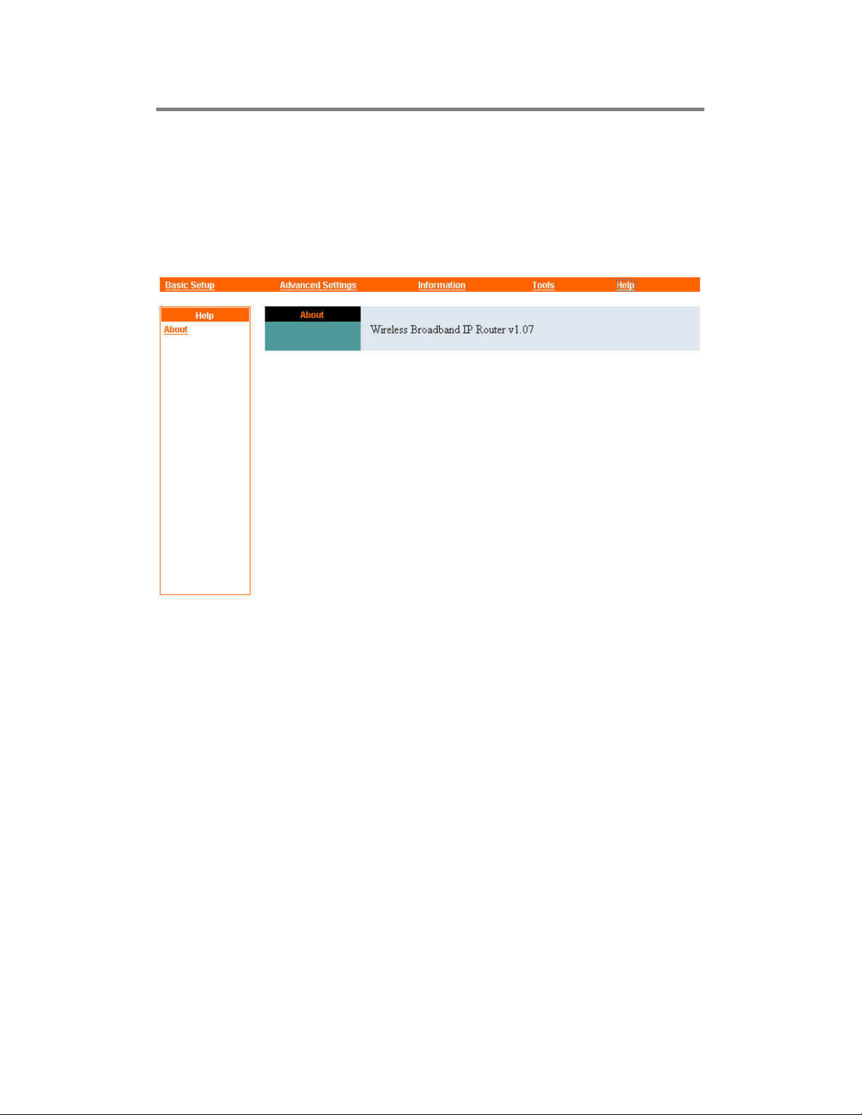
Help
The Help menu contains the
and t he version of the Wireless Gateway.
command. This command displays the full name
About
68
Page 69

Appendix
Device Utility
Device Utility is a free monitoring program designed for your convenience and may
be found in the CD-ROM shipped together with the Wireless Gateway. It may be used
to detect the existence of various devices on the network, obtain relative information,
change their IP addresses, and upgrade their firmware if necessary.
Installation
Follow these simple steps to install and launch Device Utility on your computer:
1. Insert the CD -ROM in the CD-ROM driver.
2. Launch Setup.exe found in the sub-directory “Device Utility” on the CD-ROM.
3. Follow the instructions appeared on the screen.
4. After the setup is completed, click on “Start” >> “Programs” >> “Device Utility”
>> “Device Utility v*.*” (where *.* is the version number of the Device Utility)
to launch the software. (Click on “unInstall *.*” instead of “Device Utility v*.*”
to uninstall Device Utility should it be necessary.)
5. A Device Utility application window will appear as illustrated below. At the
bottom of the window these words “Discovering Device …” will appear, followed
by “Ready” in a few seconds. The Device utility is then ready for use.
69
Page 70
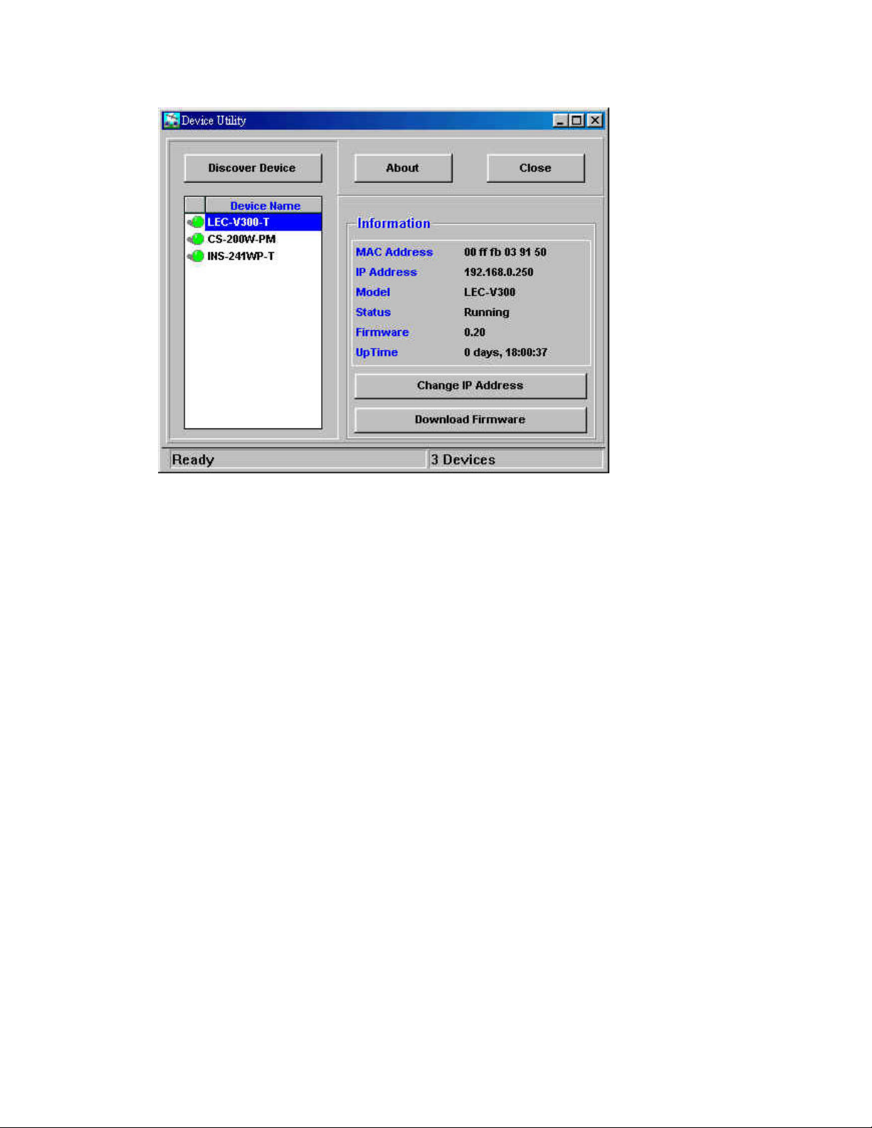
Using Device Utility
If network devices are found upon launching Device Utility, their names will appear
in the Device Name field at the left side of the Device Utility application window.
Clicking on any of the names will make the information pertaining to that particular
device appear in the Information field at the right side of the application window,
while clicking on Discover Device will enable Device Utility to re-detect all existing
network devices and refresh the name list.
The button Change IP Address may be used to change the IP address of a certain
device. Refer to the following sections for deta ils.
The button Download Firmware may be used to upgrade the firmware of a certain
device. Refer to the following sections for details.
Clicking on About will bring out a window providing the full name and version
number of Device Utility, as well as inf ormation on available memory, math
co-processor, and disk space of your computer. Click OK to close the window.
Clicking on Close will turn off Device Utility.
70
Page 71

Changing IP Address
Device Utility may be used to change the IP address of a network device. Simply
follow these steps:
1. Click on the name of the device in the Device Name list, and then click on the
button Change IP Address.
2. If the device has a password protection, a password window will appear asking the
user to enter it. Enter the password and click OK. If no password is required, no
password window will appear and you may go to Step 3 directly.
Note: Once the correct password has been entered, it will be stored for your
convenience until you exit from Device Utility and no password entry will
be required again during this session.
3. A Change IP Address window will appear. Enter the new IP address then click
OK. These new values will then be stored in the device.
Firmware Upgrade
Device Utility may be used to upgrade the firmware of a network device. Simply
follow these steps:
1. Click on the name of the device in the Device Name list, and then click on the
button Download Firmware .
2. If the device has a password protection, a password window will appear asking the
user to enter it. Enter the passw ord and click OK. If no password is required, no
password window will appear and you may go to Step 3 directly.
Note: Once the correct password has been entered, it will be stored for your
convenience until you exit from Device Utility and no password entry will
be required again during this session.
3. A Download Firmware window will appear. Enter the path and file name. If you
do not know, click on Browse to select the correct path and file. After making sure
of the correct path and file name, click OK. The device will then download the
new firmware.
71
Page 72

Specifications
External Connection
LAN Ports: 4 switched auto-negotiating 10/100Mbps Nway RJ-45 Ports, 1 Ethernet
uplink port, 1 wireless LAN standard 802.11b 11Mbps Access Point
WAN Port: 1 10Mbps Ethernet Port for connection to ADSL/cable modem
Printer Port: 1 IEEE 1284-compliant parallel port
Network Protocols Supported
TCP/IP, NAT, DHCP, HTTP, FTP, PPPoE, RIP, PPTP Pass Through
LED Report
Power, Wireless, LAN 1 to LAN 4 Link/Act, LAN 1 to LAN 4 100M, WAN Link,
WAN Act, LPT
Environmental and Physical
Power Supply: External power supply providing 5VDC/2.4A input
Operating Temperature: 0 to 50°C
Storage Temperature : -25 to 55 °C
Humidity: 5% to 95% non -condensing
Emissions: FCC Class A, CE Class A
72
 Loading...