

Page 1
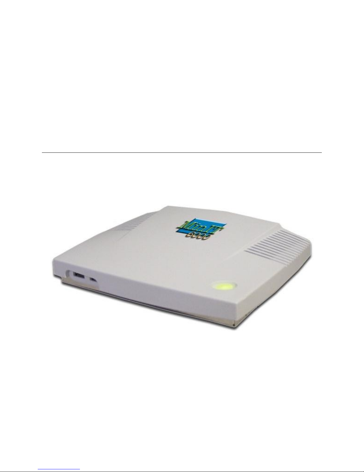
MinIT6000
User's Manual
Page 2

MiniIT6000 Windows Based Terminal Limited Warranty
Software Warranty:
NLynx warrants that for a period of ninety (90) days from the date of purchase by the End
User, its Software Products shall confirm to its published specifications under normal usage.
NLYNX DOES NOT WARRANT THAT THE OPERATION OF THE SOFTWARE WILL
BE UNINTERRUPTED OR ERROR–FREE, OR THAT ALL SOFTWARE DEFECTS
WILL BE CORRECTED. In the event a Software Product fails to comply with the warranty
set forth above, NLynx will replace the product. End User must, however, return all copies of
the Software, along with proof of purchase, to NLynx within 90 days from the Software
purchase date.
Hardware Warranty:
NLynx Technologies warrants that for one year the MinIT6000 Hardware Product shall be
free from defects in materials and workmanship which arise under proper and normal use and
service. In the event the MinIT6000 Hardware Product fails to comply with the warranty set
forth above, NLynx will replace or repair the Product. End User must, however, return the
Hardware Product, along with proof of purchase, to NLynx.
Warranty Limitations:
End User's sole remedy under any Warranty provided by NLynx shall be limited to the
replacement or repair of the Product, or at NLynx's sole discretion, a refund of the purchase
price. Transportation costs in connection with the return of any Product to and from NLynx's
plant shall be paid by the End User. NLYNX GRANTS NO WARRANTY, EXPRESS OR
IMPLIED OTHER THAN THE WARRANTIES STATED ABOVE. EXPRESSLY
EXCLUDED ARE THE IMPLIED WARRANTIES OF MERCHANTABILITY AND
FITNESS FOR A PARTICULAR PURPOSE. IN NO EVENT SHALL NYLNX BE
LIABLE FOR SPECIAL, INCIDENTAL, OR CONSEQUENTIAL DAMAGES,
INSTALLATION COSTS, LOST REVENUE OR PROFITS, OR ANY OTHER COSTS
INCURRED AS A RESULT OF THE USE OF ANY NLYNX PRODUCT, WHETHER OR
NOT USED IN ACCORDANCE WITH INSTRUCTIONS.
Printed in USA – Document 400–xxxx-01 Rev 2.11, November 2003
Page 3

Table of Contents
MINIIT6000 WINDOWS BASED TERMINAL LIMITED WARRANTY............................ 2
S
OFTWARE WARRANTY:.................................................................................................... 2
H
ARDWARE WARRANTY:................................................................................................... 2
W
ARRANTY LIMITATIONS: ................................................................................................ 2
COPYRIGHT AND TRADEMARKS ........................................................................................ 6
C
OPYRIGHT NOTICE........................................................................................................... 6
T
RADEMARKS NOTICE ....................................................................................................... 6
END USER LICENSE AGREEMENT....................................................................................... 7
E
ND USER LICENSE AGREEMENT (EULA) ....................................................................... 7
MINIT6000 GENERAL SPECIFICATIONS .......................................................................... 12
TERMINAL INSTALLATION................................................................................................. 13
M
INIT 6000 THIN CLIENT TERMINAL ............................................................................ 13
B
ASIC HARDWARE INSTALLATION .................................................................................. 14
M
OUNTING THE TERMINAL ............................................................................................. 14
U
SING THE TERMINAL...................................................................................................... 14
SETUP WIZARD........................................................................................................................ 15
A
BOUT............................................................................................................................... 15
W
ELCOME WINDOW ........................................................................................................ 15
CONNECTION MANAGEMENT............................................................................................ 22
C
ONNECTIONS MANAGEMENT......................................................................................... 22
CREATING A NEW CONNECTION...................................................................................... 26
C
REATING A NEW CONNECTION..................................................................................... 26
REATE A RDP CONNECTION ......................................................................................... 27
C
C
REATE AN ICA CONNECTION........................................................................................ 29
EDITING A CONNECTION..................................................................................................... 36
E
DITING A CONNECTION.................................................................................................. 36
E
DITING AN ICA CONNECTION ....................................................................................... 38
GENERAL SETTINGS AND INFORMATION ..................................................................... 42
TARTING PROGRAMS...................................................................................................... 42
S
S
TARTING MULTIPLE SESSIONS....................................................................................... 42
A
RRANGE DESKTOP ICONS .............................................................................................. 42
M
OVE DESKTOP ICONS .................................................................................................... 42
OGGLE OR SWITCH BETWEEN SESSIONS AND / OR WINDOWS...................................... 42
T
J
UMP TO DESKTOP FROM SESSION OR APPLICATION WINDOW..................................... 43
HANGE TASKBAR SETTINGS .......................................................................................... 43
C
M
ULTIPLE TASKBARS ...................................................................................................... 44
Page 4

CONFIGURE TERMINAL PROPERTIES ............................................................................ 45
C
ONTROL PANEL.............................................................................................................. 45
D
ATE / TIME ..................................................................................................................... 46
D
ESKTOP STYLE ............................................................................................................... 46
D
ISPLAY............................................................................................................................ 47
E
DGEPORT ........................................................................................................................ 48
FTP U
ICA S
I
I
LPD S
N
O
P
RDP S
S
PDATE WINDOW .................................................................................................... 49
ETTING.................................................................................................................... 50
NPUT & VOLUME ............................................................................................................ 55
NTERNET SETTINGS......................................................................................................... 56
ETTING................................................................................................................... 58
ETWORK.........................................................................................................................59
PTIONS............................................................................................................................ 62
RINTERS.......................................................................................................................... 63
ETTING................................................................................................................... 67
ECURITY.......................................................................................................................... 69
SNMP............................................................................................................................... 70
S
YSTEM............................................................................................................................. 71
T
HINPRINT ....................................................................................................................... 72
NLYNX TN5250 TERMINAL EMULATION......................................................................... 74
5250 T
5250 P
S
U
O
E
ERMINAL SESSION SETUP ..................................................................................... 74
RINTER SESSION SETUP......................................................................................... 76
TARTING A SESSION........................................................................................................ 78
SING THE TOOLBAR BUTTONS....................................................................................... 80
THER MENU FUNCTIONS ............................................................................................... 81
DITING SESSION PROPERTIES ........................................................................................ 82
TEXT TERMINAL EMULATOR............................................................................................ 87
CITRIX ICA CLIENT ...............................................................................................................87
EMAIL USER'S GUIDE............................................................................................................ 88
BOUT............................................................................................................................... 88
A
S
TARTING EMAIL ............................................................................................................. 88
S
ETUP MAIL SERVICE ...................................................................................................... 89
D
OWNLOAD MESSAGES FROM SERVER...........................................................................93
R
EPLY TO OR FORWARD A MESSAGE...............................................................................94
C
REATE A NEW MESSAGE................................................................................................. 94
DDRESS BOOK ................................................................................................................ 95
A
E
DIT EMAIL OPTIONS ...................................................................................................... 95
V
IEWING ATTACHMENTS................................................................................................. 97
S
AVING EMAIL ATTACHMENTS ....................................................................................... 98
T
OOLBAR BUTTONS.......................................................................................................... 99
Page 5

GENERAL INFORMATION................................................................................................ 100
USING INTERNET EXPLORER........................................................................................... 101
A
BOUT............................................................................................................................. 101
C
ONNECT TO THE INTERNET VIA AN ETHERNET LAN ................................................. 101
I
NTERNET OPTIONS........................................................................................................ 101
P
RINTING ........................................................................................................................ 103
F
AVORITES...................................................................................................................... 104
A
DDITIONAL MENU BAR ITEMS..................................................................................... 106
N
AVIGATING USING THE TOOLBAR .............................................................................. 108
A
DDRESS BAR ................................................................................................................. 108
SHARED NETWORK DRIVES ............................................................................................. 109
A
BOUT............................................................................................................................. 109
HARING A NETWORK DRIVE / FOLDER ON A WINDOWS 95/98 PC............................. 109
S
C
REATING DESKTOP SHORTCUT TO A SHARED NETWORK DRIVE / FOLDER.............. 109
A
CCESSING A SHARED DRIVE ........................................................................................ 111
UPGRADE UTILITIES ........................................................................................................... 114
FTP F
IRMWARE UPGRADE ............................................................................................ 114
TROUBLESHOOTING........................................................................................................... 117
A
BOUT............................................................................................................................. 117
1. M
INIT6000 CONFIGURATION PROBLEMS................................................................. 117
2. N
ETWORK PROBLEMS................................................................................................ 119
3. P
ERCEIVED 5250 HOST PROBLEMS ........................................................................... 121
4. 5250 H
5. P
OST PROBLEMS............................................................................................... 122
RINTER PROBLEMS................................................................................................... 126
Page 6

Copyright and Trademarks
Copyright Notice
This manual, as well as the software described in it, is furnished under license. No part of this
publication may be reproduced, transmitted, stored in a retrieval system, or translated into any
human or computer language, in any form or by any means, electronic, mechanical, magnetic,
optical, chemical, manual or otherwise, without the prior written permission of NLynx
Technologies.
© 2003 NLynx Technologies, Inc. All rights reserved.
Note: Information in this document is subject to change without notice.
Trademarks Notice
Microsoft® is registered trademarks of Microsoft® Corporation.
• Windows
• ICA
• MetaFrame
• Micro Touch
• Ericom
®
is registered trademarks of Microsoft® Corporation.
®
is a registered trademark of Citrix® Systems Inc.
®
is a trademark of Citrix® Systems Inc.
®
is a trademark of Micro Touch® Inc.
®
and PowerTerm® are registered trademarks of Ericom® Software Ltd.
• Other company and brand, product and service names are trademarks or registered
trademarks of their respective holders.
Page 7

End User License Agreement
End User License Agreement (EULA)
EULA for Microsoft Windows CE Operating System for Windows-based Terminal Devices
IMPORTANT—READ CAREFULLY
This End User License Agreement (EULA) is a legal agreement between you (either an individual or a
single entity) and the manufacturer (MANUFACTURER) of the special purpose computing device
(SYSTEM) you acquired which includes certain Microsoft software product(s) installed on the SYSTEM
and/or included in the SYSTEM package (SOFTWARE). The SOFTWARE includes computer software,
the associated media, any printed materials, and any online or electronic docum ent at i on. B y instal l i ng,
copying or otherwise using the SOFTWARE, you agree to be bound by the terms of this EULA. If you do
not agree to the terms of this EULA, MANUFACTURER and Microsoft Licensing, Inc. (MS) are unwilling
to license the SOFTWARE to you. In such event, you may not use or copy the SOFTWARE, and you
should promptly contact MANUFACTURER for instructions on return of the unused product(s) for a
refund.
SOFTWARE LICENSE
The SOFTWARE is protected by copyright laws and international copyright treaties, as well as other
intellectual property laws and treaties. The SOFTWARE is licensed, not sold.
1. GRANT OF LICENSE
SOFTWARE includes software already installed on the SYSTEM (SYSTEM SOFTWARE) and, if
included in the SYSTEM package, software contained on the CD-ROM disk and/or floppy disk(s) labeled
"Desktop Software for Microsoft Windows CE" (DESKTOP SOFTWARE). This EULA grants you the
following rights to the SOFTWARE:
System Software.
•
You may use the SYSTEM SOFTWARE only as installed in the SYSTEM.
•
Desktop Software.
DESKTOP SOFTWARE might not be included with your SYSTEM. If DESKTOP SOFTWARE is
included with your SYSTEM, you may install and use the component(s) of the DESKTOP SOFTWARE in
accordance with the terms of the end user license agreement provided with such component(s). In the
absence of a separate end user license agreement for particular component(s) of the DESKTOP
SOFTWARE, you may install and use only one (1) copy of such component(s) on a single computer with
which you use the SYSTEM.
Use of Windows CE Operating System for Windows-Based Terminal Devices with
•
Microsoft Windows NT Server, Terminal Server Edition.
If the SOFTWARE is Windows CE operating system for Windows-Based Terminal devices, the following
special provisions apply. In order to use the SYSTEM in connection with Windows NT Server, Terminal
Server Edition, you must possess (1) a Client Access License for Windows NT Server, Terminal Server
Edition and (2) an end user license for Windows NT Workstation or an end user license agreement for
Windows NT Workstation for Windows-Based Terminal Devices (please refer to the end user license
agreement for Windows NT Server, Terminal Server Edition for additional information).
MANUFACTURER may have included a Certificate of Authenticity for Windows NT Workstation for
Windows-Based Terminal Devices with the SYSTEM. In that case, this EULA constitutes an end user
license for the version of Windows NT Workstation for Windows-Based Terminal Devices indicated on
such Certificate of Authenticity.
Back-up Copy.
•
If MANUFACTURER has not included a back-up copy of the SYSTEM SOFTWARE with the SYSTEM,
you may make a single back-up copy of the SYSTEM SOFTWARE. You may use the back-up copy solely
for archival purposes.
Page 8

2. Description of Other Rights and Limitations.
• Speech/Handwriting Recognition
If the SYSTEM SOFTWARE includes speech and/or handwriting recognition component(s), you should
understand that speech and handwriting recognition are inherently statistical processes; that recognition
errors are inherent in the processes; that it is your responsibility to provide for handling such errors and to
monitor the recognition processes and correct any errors. Neither MANUFACTURER nor its suppliers
shall be liable for any damages arising out of errors in the speech and handwriting recognition processes.
•
Limitations on Reverse Engineering, Recompilation and Disassembly
You may not reverse engineer, decompile, or disassemble the SYSTEM SOFTWARE, except and only to
the extent that such activity is expressly permitted by applicable law notwithstanding this limitation.
•
Single SYSTEM
The SYSTEM SOFTWARE is licensed with the SYSTEM as a single integrated product. The SYSTEM
SOFTWARE installed in Read Only Memory (ROM) of the SYSTEM may only be used as part of the
SYSTEM.
•
Single EULA
The package for the SYSTEM SOFTWARE may contain multiple versions of this EULA, such as multiple
translations and/or multiple media versions (e.g., in the user documentation and in the software). Even if
you receive multiple versions of the EULA, you are licensed to use only one (1) copy of the SYSTEM
SOFTWARE.
Rental
•
You may not rent or lease the SOFTWARE.
• Software Transfer
You may permanently transfer all of your rights under this EULA only as part of a sale or transfer of the
SYSTEM, provided you retain no copies, you transfer all of the SOFTWARE (including all component
parts, the media, any upgrades or backup copies, this EULA and, if applicable, the Certificate(s) of
Authenticity), and the recipient agrees to the terms of this EULA. If the SOFTWARE is an upgrade, any
transfer must include all prior versions of the SOFTWARE.
•
Termination
Without prejudice to any other rights, MANUFACTURER or MS may terminate this EULA if you fail to
comply with the terms and conditions of this EULA. In such event, you must destroy all copies of the
SOFTWARE and all of its component parts.
3. Upgrades.
If the SYSTEM SOFTWARE and this EULA are provided separate from the SYSTEM by
MANUFACTURER and the SYSTEM SOFTWARE is on a ROM chip, CD ROM disk(s) or floppy disk(s),
and labeled "For ROM Upgrade Purposes Only" ("ROM Upgrade"), you may install one copy of the ROM
Upgrade onto the SYSTEM as a replacement copy for the SYSTEM SOFTWARE originally installed on
the SYSTEM and use it in accordance with Section 1 of this EULA.
4. Copyright.
All title and copyrights in and to the SOFTWARE (including but not limited to any images, photographs ,
animations, video, audio, music, text and "applets," incorporated into the SOFTWARE), the accompanying
printed materials, and any copies of the SOFTWARE, are owned by MS or its suppliers (including
Microsoft Corporation). You may not copy the printed materials accompanying the SOFTWARE. All
rights not specifically granted under this EULA are reserved by MS and its suppliers (including Microsoft
Corporation).
5. Product Support.
Product support for the SOFTWARE is not provided by MS, its parent corporation, Microsoft Corporation,
or their affiliates or subsidiaries. For product support, please refer to MANUFACTURER’s support number
provided in the documentation for the SYSTEM. Should you have any questions concerning this EULA, or
Page 9

if you desire to contact MANUFACTURER for any other reason, please refer to the address provided in the
documentation for the SYSTEM.
6. Export Restrictions.
You agree that you will not export or re-export the SOFTWARE to any country, person, or entity subject to
U.S. export restrictions. You specifically agree not to export or re-export the SOFTWARE: (i) to any
country to which the U.S. has embargoed or restricted the export of goods or services, which as of March
1998 include, but are not necessarily limite d to Cuba, Iran, Iraq, Libya, North Korea, Sudan and Syria, or to
any national of any such country, wherever located, who intends to transmit or transport the products back
to such country; (ii) to any person or entity who you know or have reason to know will utilize the
SOFTWARE or portion thereof in the design, development or production of nuclear, chemical or biological
weapons; or (iii) to any person or entity who has been prohibited from participating in U.S. export
transactions by any federal agency of the U.S. government.
If the SOFTWARE is labeled "North America Only Version" above, on the Product Identification Card, or
on the SOFTWARE packaging or other written materials, then the following ap plies: The SOFTWARE is
intended for distribution only in the United States, its territories and possessions (including Puerto Rico,
Guam, and U.S. Virgin Islands) and Canada. Export of the SOFTWARE from the United States is
regulated under "EI controls" of the Export Administration Regulations (EAR, 15 CFR 730-744) of the
U.S. Commerce Department, Bureau of Export Administration (BXA). A license is required to export the
SOFTWARE outside the United States or Canada. You agree that you will not directly or indirectly, export
or re-export the SOFTWARE (or portions thereof) to any country, other than Canada, or to any person or
entity subject to U.S. export restrictions without first obtaining a Commerce Department export license.
You warrant and represent that neither the BXA nor any other U.S. federal agency has suspended, revoked
or denied your export privileges.
7. Note on Java Support.
The SYSTEM SOFTWARE may contain support for programs written in Java. Java technology is not fault
tolerant and is not designed, manufactured, or intended for use or resale as on-line control equipment in
hazardous environments requiring fail-safe performance, such as in the operation of nuclear facilities,
aircraft navigation or communication systems, air traffic control, dir ect life support machines, or weapons
systems, in which the failure of Java technology could lead directly to death, personal injury, or severe
physical or environmental damage.
8. Limited Warranty.
• Limited Warranty
MANUFACTURER warrants that the SOFTWARE will perform substantially in accordance with the
accompanying written materials for a period of ninety (90) days from the date of receipt. Any implied
warranties on the SOFTWARE are limited to ninety (90) days. Some states/jurisdictions do not allow
limitations on duration of an implied warranty, so the above limitation may not apply to you.
• Customer Remedies
MANUFACTURER’S and its suppliers’ entire liability and your exclusive remedy shall be, at
MANUFACTURER’S option, either (a) return of the price paid, or (b) repair or replacement of the
SOFTWARE that does not meet the above Limited Warranty and which is returned to MANUFACTURER
with a copy of your receipt. This Limited Warranty is void if failure of the SOFTWARE has resulted from
accident, abuse, or misapplication. Any replacement SOFTWARE will be warranted for the remainder of
the original warranty period or thirty (30) days, whichever is longer.
•
No Other Warranties
EXCEPT AS EXPRESSLY PROVIDED IN THE LIMITED WARRANTY SECTION ABOVE, THE
SOFTWARE IS PROVIDED TO THE END USER "AS IS" WITHOUT WARRANTY OF ANY KIND,
EITHER EXPRESSED OR IMPLIED, INCLUDING, BUT NOT LIMITED TO, WARRANTIES OF
NON- INFRINGEMENT, MERCHANTABILITY, AND/OR FITNESS FOR A PARTICULAR
PURPOSE. THE ENTIRE RISK OF THE QUALITY AND PERFORMANCE OF THE SOFTWARE IS
WITH YOU.
Page 10

• No Liability for Consequential Damages
MANUFACTURER OR MANUFACTURER’S SUPPLIERS, INCLUDING MS AND ITS SUPPLIERS,
SHALL NOT BE HELD TO ANY LIABILITY FOR ANY DAMAGES SUFFERED OR INCURRED BY
THE END USER (INCLUDING, BUT NOT LIMITED TO, GENERAL, SPECIAL, CONSEQUENTIAL
OR INCIDENTAL DAMAGES INCLUDING DAMAGES FOR LOSS OF BUSINESS PROFITS,
BUSINESS INTERRUPTION, LOSS OF BUSINESS INFORMATION AND THE LIKE), ARISING
FROM OR IN CONNECTION WITH THE DELIVERY, USE OR PERFORMA NCE OF THE
SOFTWARE.
If you acquired this EULA in the United States, this EULA is governed by the laws of the State of Washington.
If you acquired this EULA in Canada, this EULA is governed by the laws of the Province of Ontario, Canada. Each
of the parties hereto irrevocably attorneys to the jurisdiction of the courts of the Province of Ontario and further
agrees to commence any litigation which may arise hereunder in the courts located in the Judicial District of York,
Province of Ontario.
If this EULA was acquired outside the United States, then local law may apply.
Should you have any questions concerning this EULA, please contact the MANUFACTURER of your SYSTEM.
U.S. GOVERNMENT RESTRICTED RIGHTS
The SOFTWARE and documentation are provided with RESTRICTED RIGHTS. Use, duplication, or disclosure by
the Government is subject to restrictions as set forth in subparagraph (c)(1)(ii) of the Rights in Technical Data and
Computer Software clause at DFARS 252.227 - 70 1 3 or s u b para graphs (c)(1) and (2) of the Commercial Computer
Software—Restricted Rights at 48 CFR 52.227- 19, as applicable. MANUFACTURER is Microsoft
Corporation/One Microsoft Way/R e dmond, WA 98052-6399.
EULA for Microsoft Windows CE Operating System
IMPORTANT—READ CAREFULLY
IF YOU DO NOT AGREE TO THIS END USER LICENSE AGREEMENT (“EULA”), DO
NOT USE THE DEVICE OR COPY THE SOFTWARE
INSTEAD, PROMPTLY CONTACT [COMPANY] FOR INSTRUCTIONS ON RETURN OF THE UNUSED
DEVICE (S) FOR A REFUND. ANY USE OF THE SOFTWARE, INCLUDING BUT NOT LIMITED TO
USE ON THE DEVICE, WILL CONSTITUTE YOUR AGREEMENT TO THIS EULA (OR
RATIFICATION OF ANY PREVIOUS CONSENT).
GRANT OF SOFTWARE LICENSE. This EULA grants you the following license:
• You may use the SOFTWARE only on the DEVICE.
• NOT FAULT TOLERANT. THE SOFTWARE IS NOT FAULT TOLERANT.
[COMPANY] HAS INDEPENDENTLY DETERMINED HOW TO USE THE
SOFTWARE IN THE DEVICE, AND MS HAS RELIED UPON [COMPANY] TO
CONDUCT SUFFICIENT TESTING TO DETERMINE THAT THE SOFTWARE IS
SUIT ABLE FOR SUCH USE.
• NO WARRANTIES FOR THE SOFTWARE. THE SOFTWARE is provided “AS IS”
and with all faults. THE ENTIRE RISK AS TO SATISFACTORY QUALITY,
PERFORMANCE, ACCURACY, AND EFFORT (INCLUDING LACK OF
NEGLIGENCE) IS WITH YOU. ALSO, THERE IS NO WARRANTY AGAINST
INTERFERENCE WITH YOUR ENJOYMENT OF THE SOFTWARE OR
AGAINST INFRINGEMENT. IF YOU HAVE RECEIVED ANY WARRANTIES
REGARDING THE DEVICE OF THE SOFTWARE, THOSE WARRANTIES DO NOT
ORIGINATE FROM, AND ARE NOT BINDING ON, MS.
Page 11

• Note on Java Support. The SOFTWARE may contain support for programs written in
Java technology is not fault tolerant and is not designed, manufactured, or intended for
use or resale as online control equipment in hazardous environments requiring fail-safe
performance, such as in the operation of nuclear facilities, aircraft navigation or
communication systems, air traffic control, direct life support machines, or weapons
systems, in which the failure of Java technology could lead directly to death, personal
injury, or severe physical or environmental damage. Sun Microsystems, Inc. has
contractually obligated MS to make this disclaimer.
• No Liability for Certain Damages. EXCEPT AS PROHIBITED BY LAW, MS
SHALL HAVE NO LIABILITY FOR ANY INDIRECT, SPECIAL,
CONSEQUENTIAL OR INCIDENTIAL DAMAGES ARISING FROM OR IN
CONNECTION WITH THE USE OR PERFORMANCE OF THE SOFTWARE.
THIS LIMITATION SHALL APPLY EVEN IF ANY REMEDY FAILS OF ITS
ESSENTIAL PURPOSE. IN NO EVENT SHALL MS BE LIABLE FOR ANY
AMOUNT IN EXCESS OF U.S. TWO HUNDRED FIFTY DOLLARS
(U.S.$250.00).
• Limitation on Reverse Engineering, Decompilation, and Disassembly. You may not
reverse engineer, decompile, or disassemble the SOFTWARE, except and only to the
extent that such activity is expressly permitted by applicable law notwithstanding this
limitation.
• SOFTWARE TRANSFER ALLOWED BUT WITH RESTRICTIONS. You may
permanently transfer rights under this EULA only as part of a permanent sale or transfer
of the Device, and only if the recipient agrees to this EULA. If the SOFTWARE is an
upgrade, any transfer must also include all prior versions of the SOFTWARE.
• EXPORT RESTRICTIONS. You acknowledge that SOFTWARE is of US-origin. You
agree to comply with all applicable and national law that apply to the SOFTWARE,
including the U.S. Export Administration Regulations, as well as end-user, and country
destination restriction issued by U.S. and other governments. For additional information
on exporting the SOFTWARE, see http://www.microsoft.com/exporting/.
Page 12
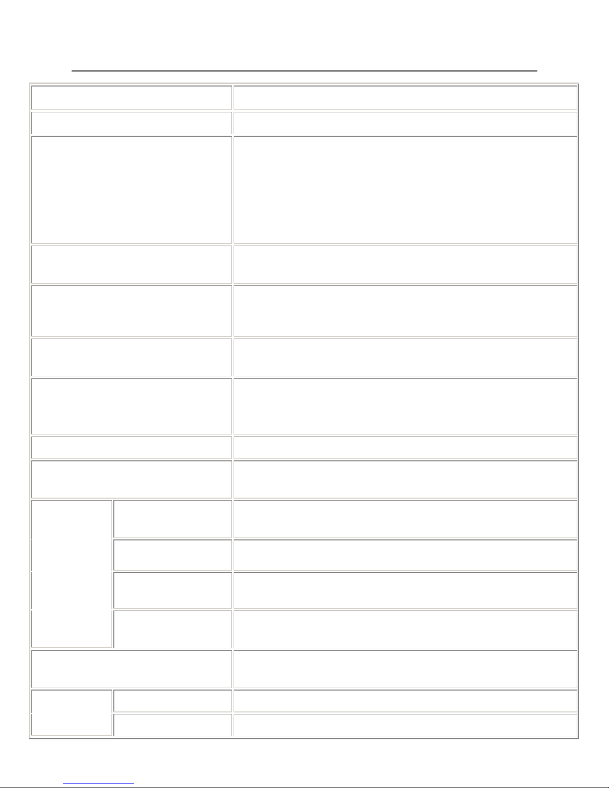
MinIT6000 General Specifications
Items Specifications
Processor
Communication
Embedded O.S.
Display Resolution
Memory
Server Operating System Support
• SIS 550 200 MHz processor
• Microsoft RDP and Citrix ICA protocol compliant
• 10/100 dual speed Ethernet, Twisted Pair (RJ45)
• One parallel port (DB-25 Female connector)
• Enhanced ps/2 keyboard interface
• Enhanced ps/2 mouse interface
• Two USB ports
• Microsoft Windows CE4.2
• Microsoft IE 6.0
• Support 640x480, 800x600, 1024x768, 1280x1024 with high
color.
• Flicker free, max. up to 85 Hz
• SDRAM -- 64 MB SDRAM standard. (Max. 256MB)
• Flash -- 16 MB DOC standard. (Max. 64MB)
• Microsoft Windows 2000 (Server Edition)
• Microsoft Windows NT 4.0 (TSE)
Option Devices
Option Software
Temperature
Relative Humidity
Environment
Operating Altitude
Range
Power
Regulatory Compliance
Physical
Characteristics
Dimension (WxDxH)
Weight
• Citrix MetaFrame, Citrix WinFrame
• USB storage device
• Text Terminal Emulation (PowerTerm)
• Remote Management (Remote Director)
• Operating : 5 ºC to 40 ºC (41 ºF to 104 ºF)
• Storage : -40 ºC to 60 ºC (-4 ºF to 140 ºF)
• 90% maximum, non-condensing
• 0 to 10,000 feet (0 to 3050 meters)
• Full range auto-sensing 100 ~ 240 VAC at 50 Hz ~ 60 Hz
• 10 Watts
• UL, C-UL, TUV
• FCC Class B, CE mark
• 194.5 x 151.5 x 40 (mm)
• 0.65 Kg
Page 13
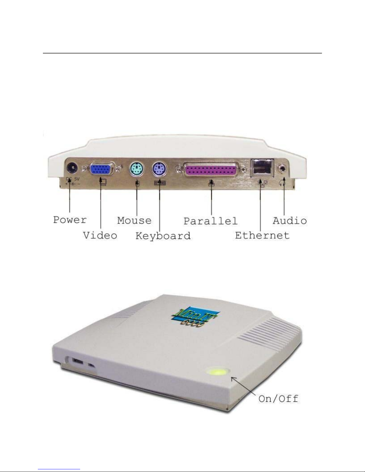
Terminal Installation
MinIT 6000 Thin Client Terminal
The following pictures provide a front and rear view of your new MinIT 6000 Thin
Client Terminal.
Terminal Rear Panel Connectors
Terminal Front
Page 14
Basic Hardware Installation
1. Connect the monitor to the VGA connector.
2. Connect the PS/2 keyboard to the Keyboard connector.
3. Connect the PS/2 mouse to the Mouse connector.
4. If you are ready to use a network connection, connect a CAT5 UTP cable to the
Ethernet connector.
5. Connect the power adapter cable to the Power connector.
6. Plug the power adapter AC cord into an AC outlet.
7. You are ready to use the Terminal now.
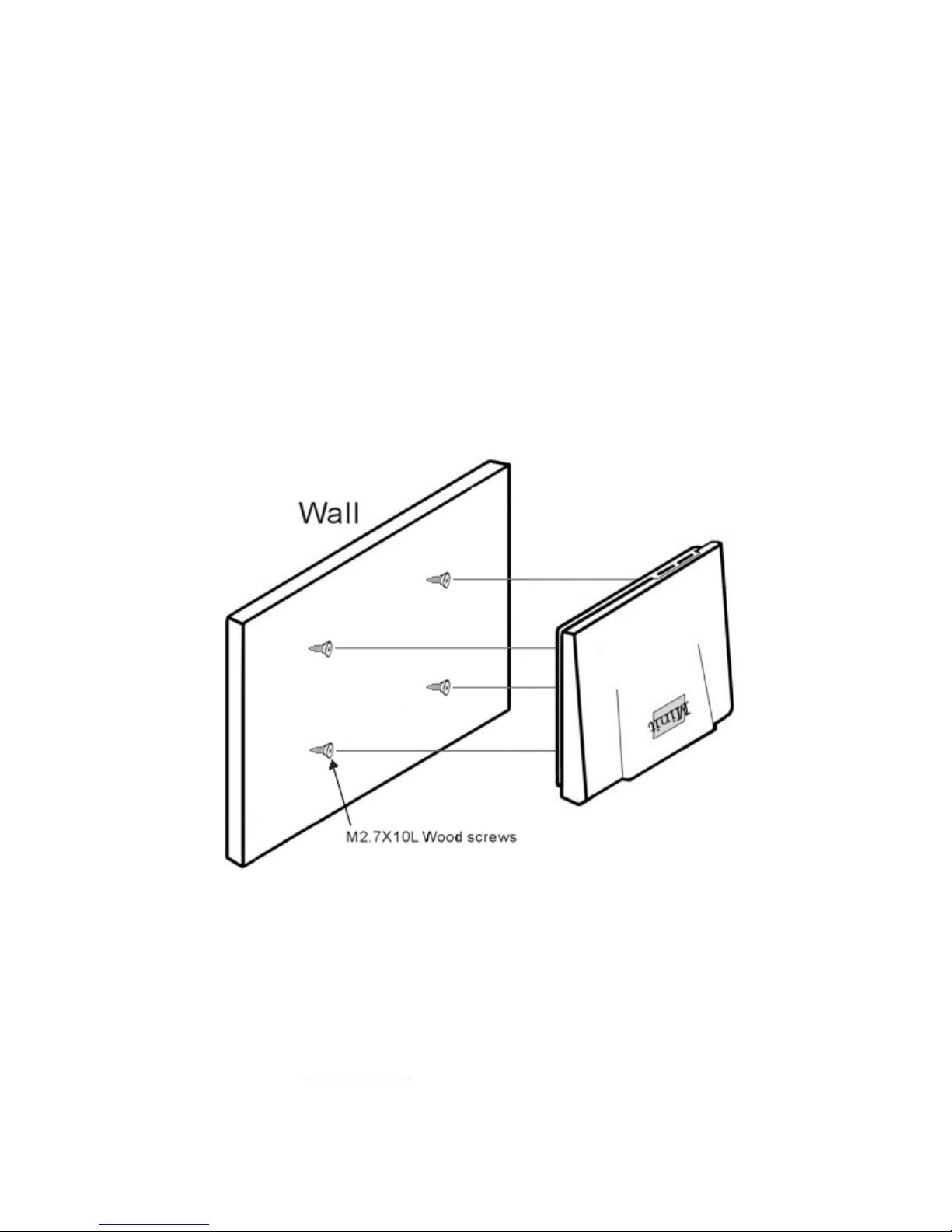
Mounting the Terminal
The terminal can be mounted permanently on a wall. The following figure shows the
Terminal mounting procedures.
Note: Use a screwdriver to fix this device on the wooden wall with the
included four M2.7x10L wood screws.
Using the Terminal
Turn on the terminal when all rear panel connections have been made.
The first dialog box of the Setup Wizard will appear after the terminal's greeting screen.
Please refer to the
Setup Wizard to describe the next step of setting up the terminal.
Page 15
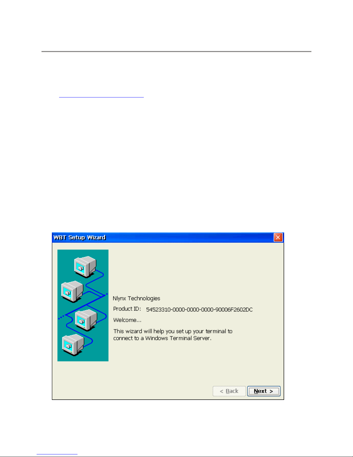
Setup Wizard
About
The Setup Wizard is used for the terminal's initial setup but will also run after re setting the unit
back to its factory defaults. To reset the unit back to its defaults, refer to the System section
under
You can use the Setup Wizard to set the basic terminal network configuration and display
parameters however; any of these parameters can be changed later by entering the “Control
Panel” and selecting the appropriate icon.
There are several dialog and configuration boxes, as shown below, that you must navigate
through to complete the Setup Wizard process.
Configure Terminal Properties.
To display the next dialog box in the sequence:
• Click the Next or Accept buttons
To return to the previous dialog box:
• Click the Back button
To quit and go directly to the Desktop:
• Click the Cancel button
Welcome Window
This dialog box shows product information.
Page 16
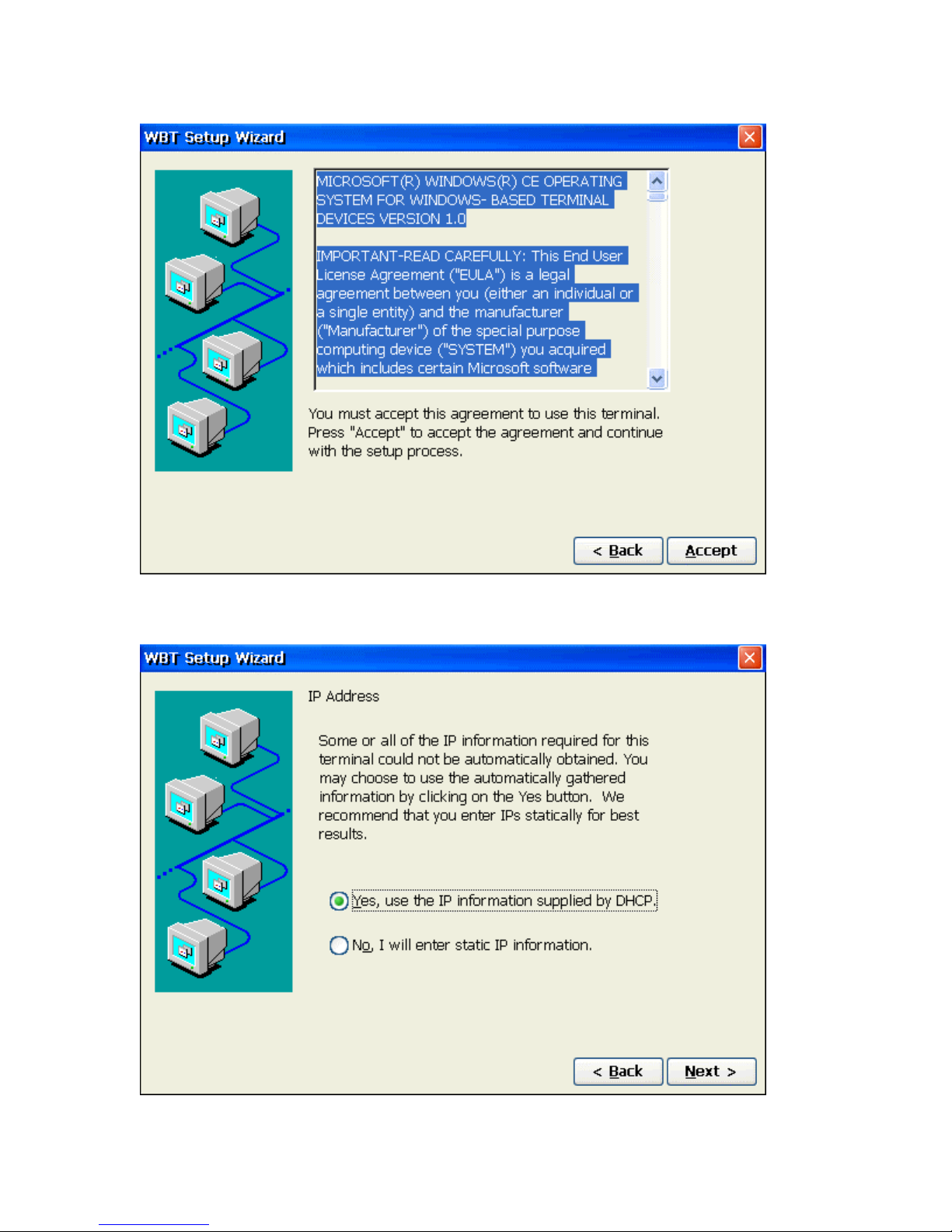
EULA (End User License Agreement)
Please read the license agreement carefully.
IP Address
Click Yes, to use the IP information supplied by DHCP server or No (an IP Address and
Page 17
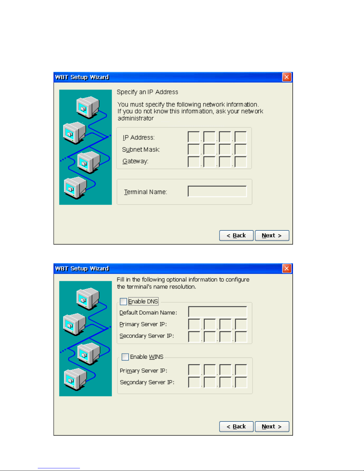
Optional Information dialog boxes will display in succession) to manually select your static
IP information as the default. Selecting Yes will take you directly to the optional
Information dialog box will display.
Specify static IP Address
Optional Information
Page 18
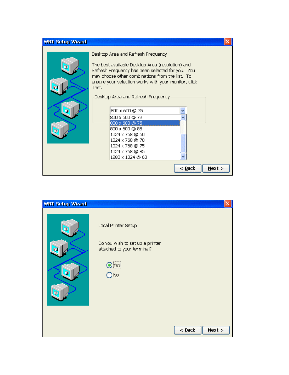
Display Settings
Printer Setup
Page 19
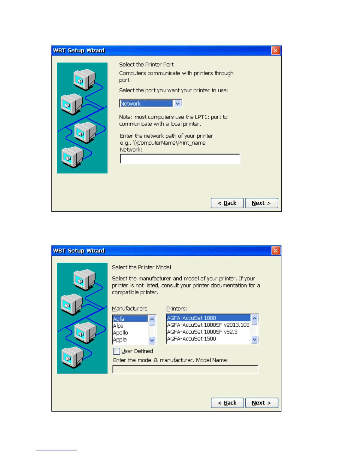
Printer Port
Note: If you select "Network" for your printer port, the "Network" entry box we become
available to type in the path information.
Printer Model
Select the Manufacturer and Model number of your printer.
Page 20
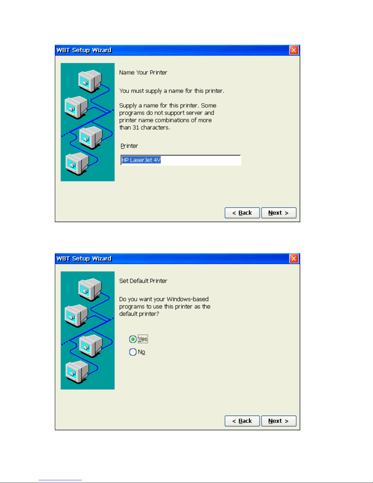
Printer Name
Set Printer Default
Page 21
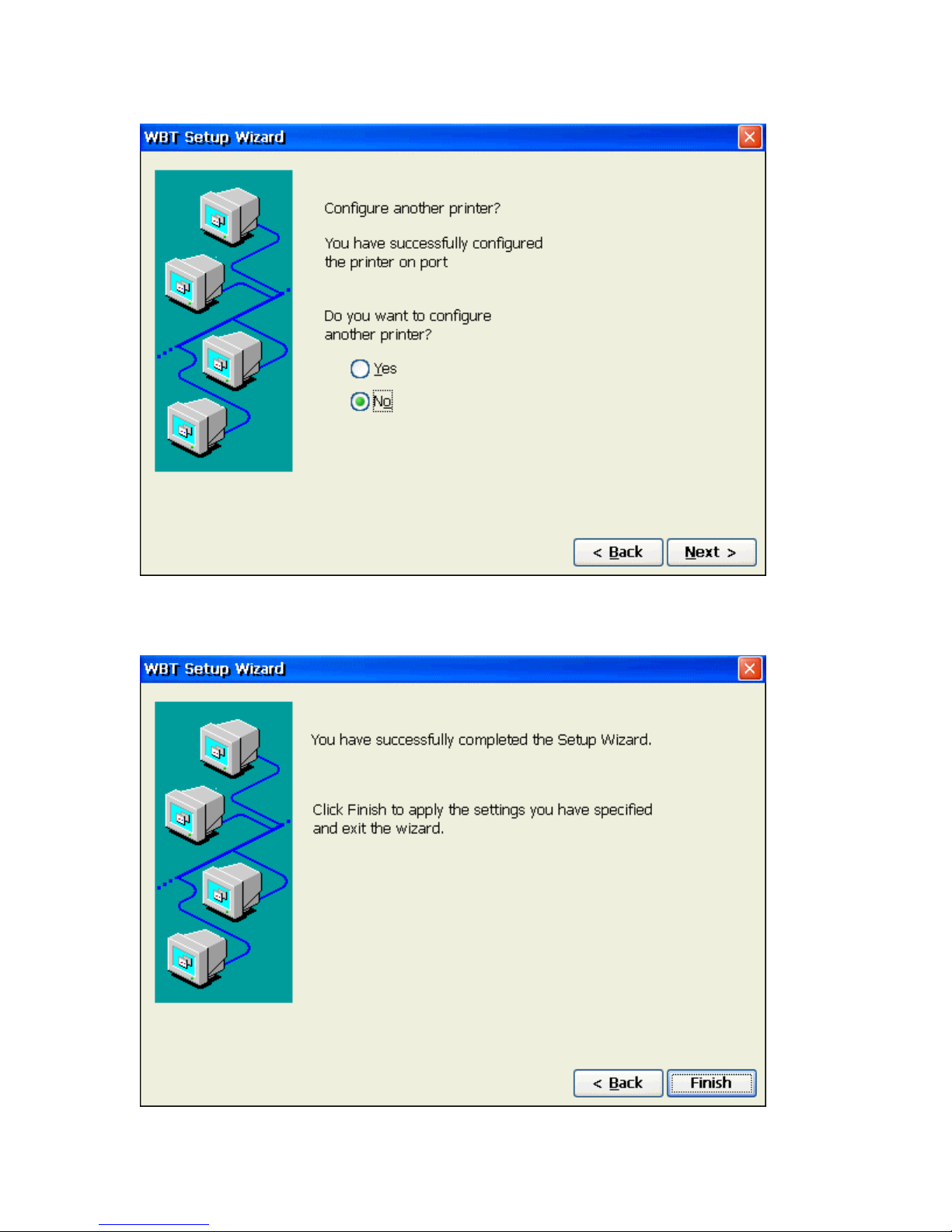
Additional Printers
If you select yes, you will be taken back to the “Printer Port” step.
Finish
• Click Finish, to apply your selections and quit the Setup Wizard.
Page 22
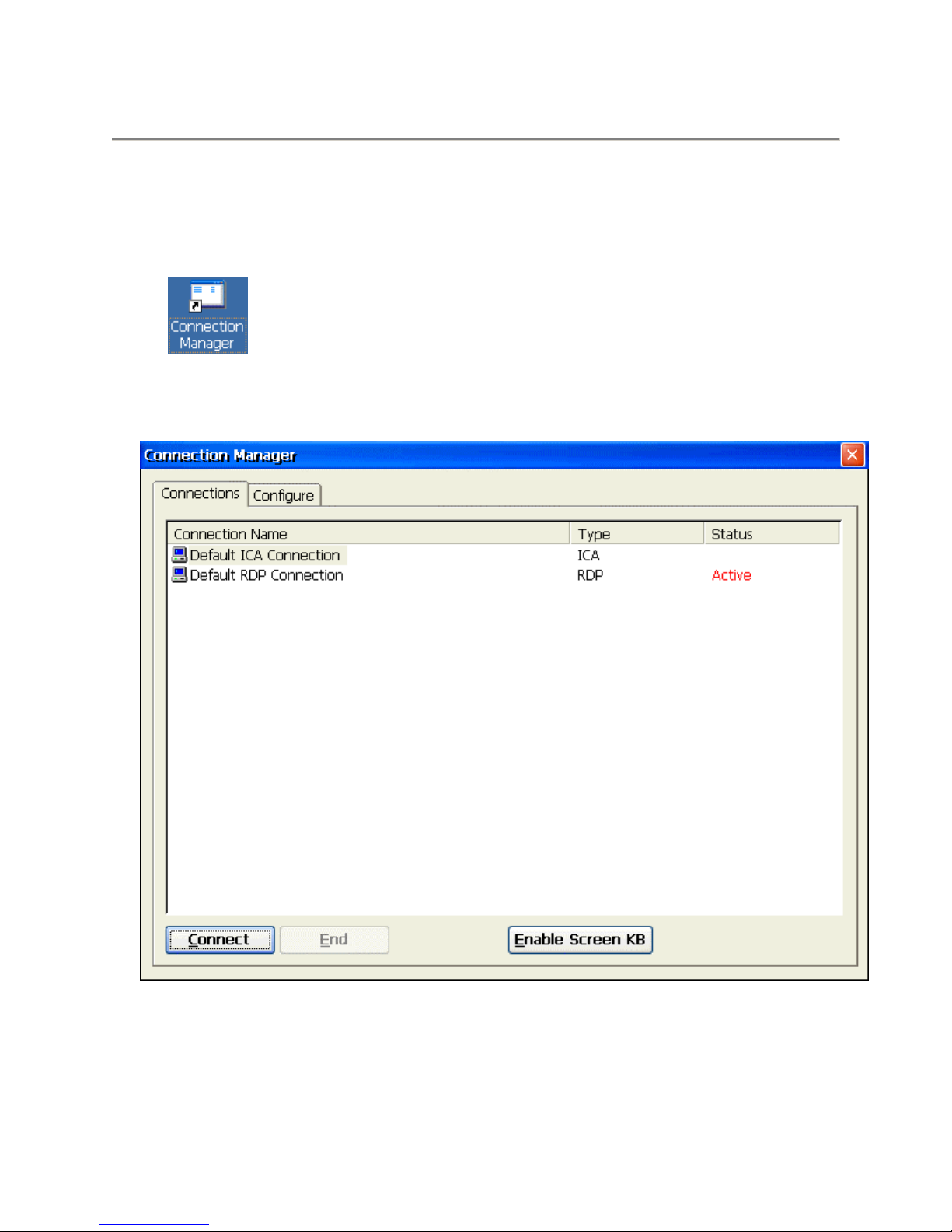
Connection Management
Connections Management
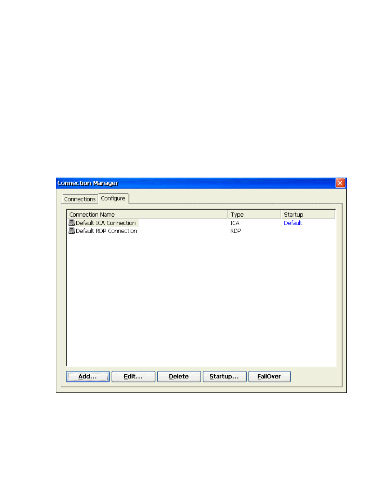
From the terminal desktop, click on the Connection Manager icon (shown below) to bring up
the Terminal Connection Manager dialog box.
Connection Manager Desktop Icon
Once the Connection Manager dialog box is open, you can select either Connections or
Configure dialog box to manage your terminal's network connections.
Connection Manager Desktop Icon
Page 23
Using the Connections Dialog Box
Use the connection manager to create or edit network connections to a specified server.
Connect
Click on the Connect button to make a network connection. You can also double-click
on a selected connection in the Connection Name to make a network connection with
server.
End
You can click on the End button to end any active connection process listed in
status field. The End is not available if your session is not active. The End
button is disabled in the default.
Using the Configure Dialog Box
The functions of the Configure Dialog Box are used to add, modify, delete, and configure
connections.
Configure Dialog Box
The Configure properties sheet contains four basic functions. The following identifies and
describes each of them.
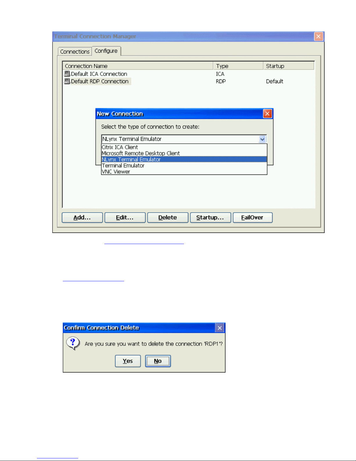
Add
Click on the Add button to create a new connection. A new connection dialog box
displays, when this button is pressed.
Page 24
Please refer to the
Creating A New Connection section for more information about
adding a different type connection.
Edit
Click on the Edit button to edit the properties of a selected connection. Please refer to the
Editing A Connection section for more information about editing a connection.
Delete
Click on the Delete button to delete a connection. When you click this button, a
“Connection” dialog box displays. Click on the Yes button to complete the
deletion. Click on the No button to cancel the deletion.
Page 25
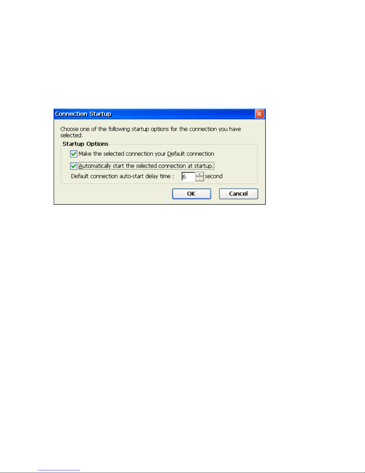
Startup
Click on the Startup button to specify which connection option you want to be
the default when the terminal first powers up. The Connection Startup dialog
box displays after the Startup button is pressed. Using the Connection Startup
dialog box, you can pre-set sessions to automatically connect to their servers
when terminal is turned on.
Connection Startup Dialog Box
Make the selected connection your default connection.
Enable this function to use the connection you selected in the "Connection
Manager" as the default connection.
Automatically start the selected connection at startup.
Enable this function to automatically start the connection you selected in the
"Connection Manager" when the terminal is turned on.
Default connection auto-start delay time:
Allows the user to adjust the auto-start delay time by changing the value. This might be
important in some networks because it allows the unit enough time to obtain DHCP
information from the DHCP server (if set for) before it tries to connect to the host.
OK
Click on OK to quit the dialog box and save the changes.
Cancel
Click on Cancel to quit the dialog box without any change.
Page 26
Creating a new Connection
Creating A New Connection
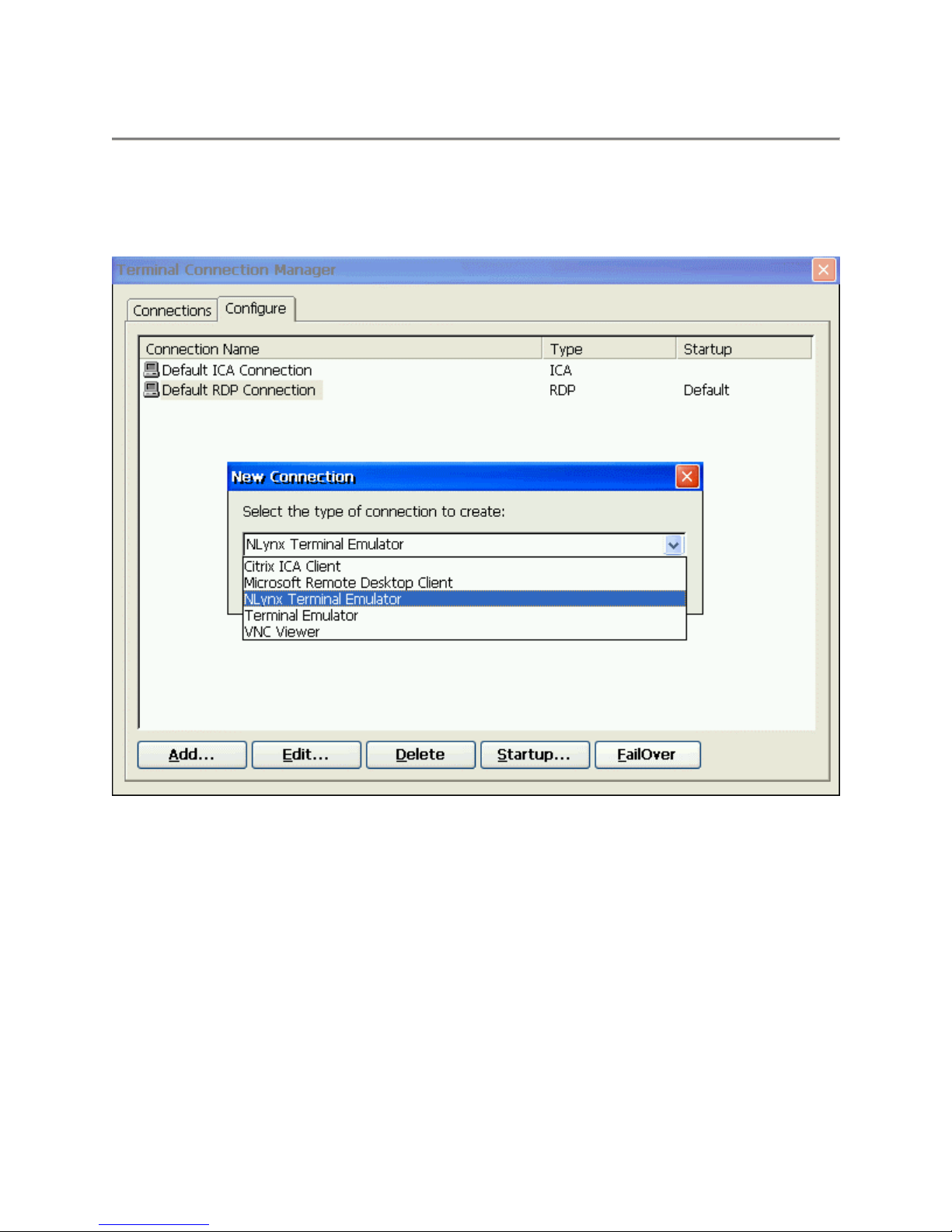
The New Connection dialog box, as follows, allow user to create new network connections.
New Connection Dialog Box
Choosing a Connection Protocol
From the pull-down list bar in the dialog box, you can select the type of connection protocol
you want to use to connect to a server. The selections available are found in the pull down
list. Click the OK button, when you have made your selection.
• Citrix ICA Client for Windows CE
The ICA (Independent Computing Architecture) client is used to connect to a Citrix ICA
Winframe or Metaframe server. If you select the Citrix ICA Client for Windows CE, the
"Specify Connection Type" dialog box displays. Using the sequence of dialog boxes,
you can create an ICA connection. Please refer to "Create an ICA Connection" for more
information.
Page 27
• Microsoft Remote Desktop Client
The RDP (Remote Desktop Protocol) client is used to connect to a TSE (Windows NT
Terminal Server Edition) server. If you select the RDP client, the Connection Wizard
displays. Using the wizard, you can create a RDP connection. Please refer to "Create a
RDP Connection" for more information.
• Terminal Emulation
The Terminal Emulation client allows you to connect to a variety of host computers such
as an IBM Mainframe or AS/400 using protocols such as 3270, 5250, and Telnet. If you
select the Terminal Emulation, the "Connection Properties" dialog box displays. Using
the dialog box, you can create a specific terminal emulator. Please refer to the
Terminal Emulator User Manual for more information.
• VNC Viewer
The VNC (Virtual Network Computing) viewer client allows you to connect to a VNC
server. This allows you to view and interact with the one computer (the “server”) located
anywhere on the internet (provided your local network has the appropriate internet
connection).
Text
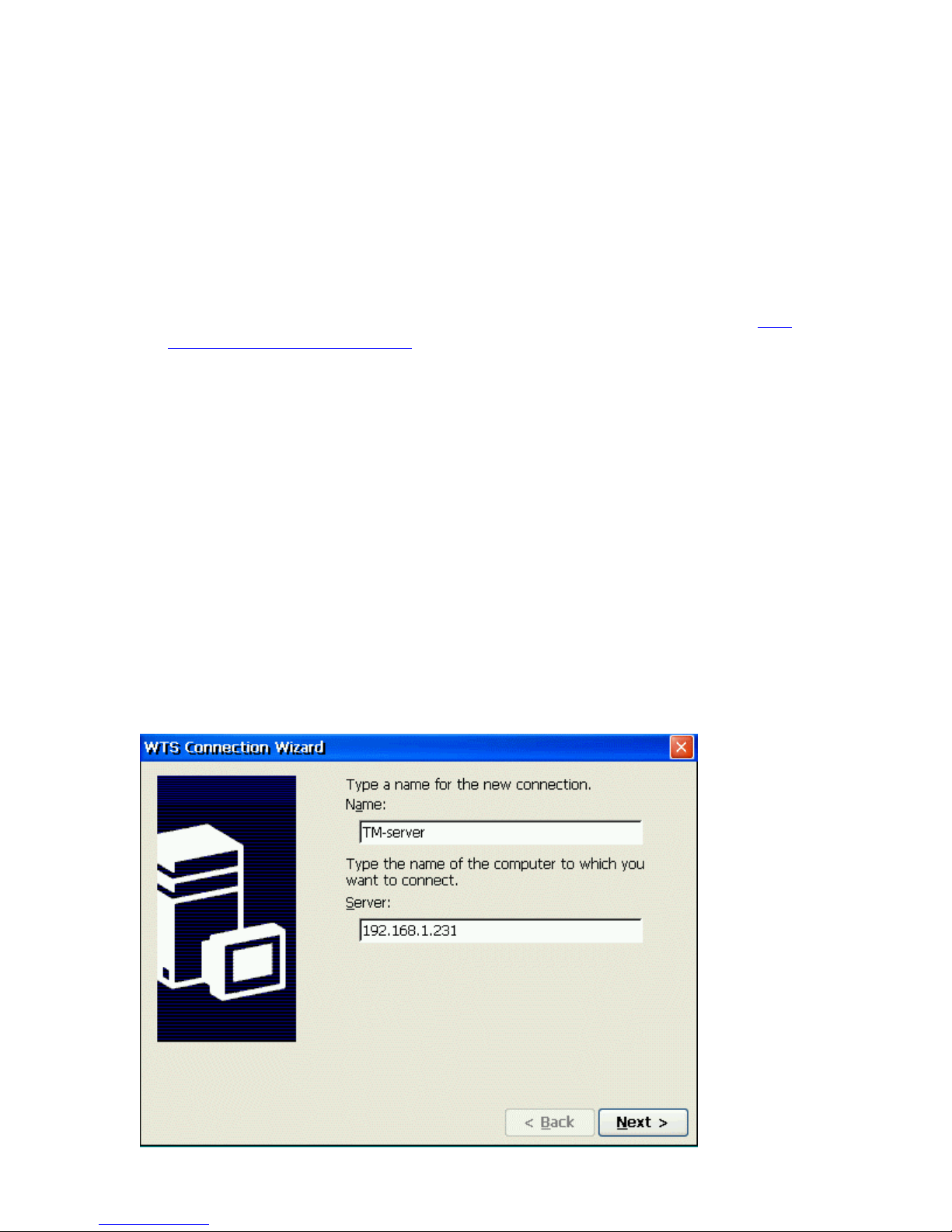
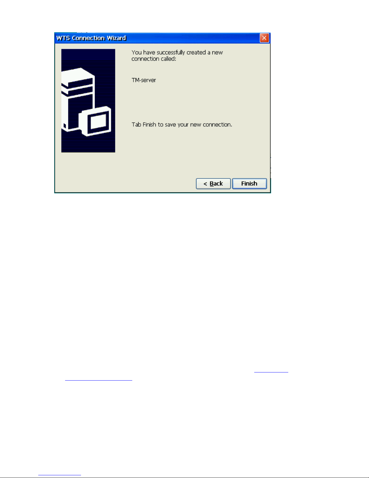
Create a RDP Connection
You can use the WTS Connection Wizard to create a new RDP connection. Click the Next
button to display the next dialog box in the sequence. Click the Back button to return to the
previous dialog box. Click the Cancel button to quit this dialog box at any time. When you are
finished, a new connection will be added to the Connection Name list in the Terminal
Connection Manager.
There are four dialog boxes, as below, for the WTS Connection Wizard process.
WTS Connection Wizard
Page 28
Type in the name that you want to refer to this RDP connection by and then type in the name
or IP address of the Server that you want to connect to.
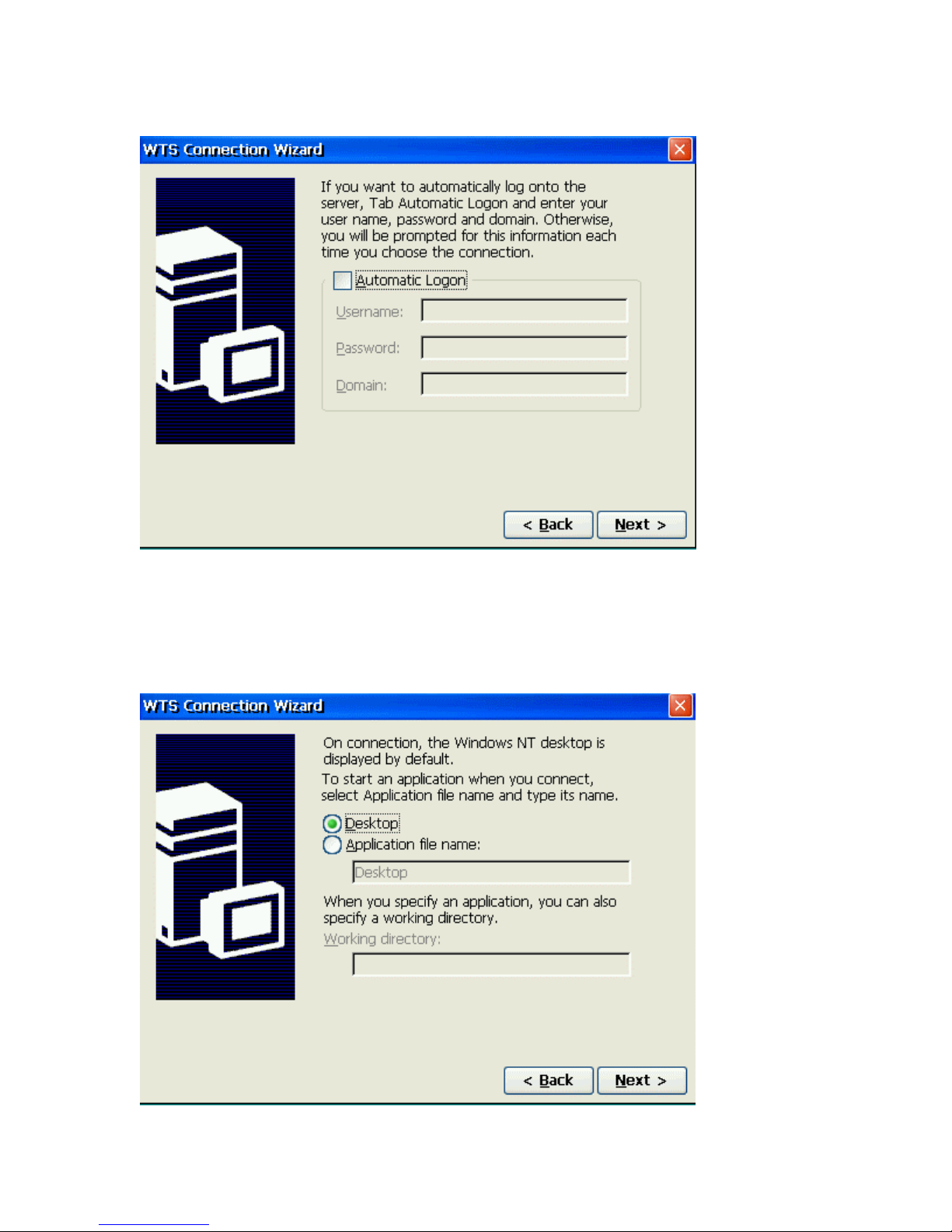
Unless you want to enter them every time you start the RDP connection, click on the
Automatic Logon check box and specify the logon Information by typing in the Username,
Password and Domain.
Page 29
Create an ICA Connection
You can configure and run two types of ICA sessions: Citrix server connections and published
applications.
• Citrix server connections allow you to connect to the Windows desktop of a
specific Citrix server; you can run any applications available on the desktop, in
any order.
• Published applications are specific applications set up by an administrator for
remote users to run. When connected, you are presented with the application
itself.
Note This procedure describes the simplest way to create a connection entry.
When you follow these steps, you set the essential items you need to connect to a
Citrix server from the Windows CE device, See "Changing a Connection Entry"
for more information about how to change the other properties for a connection
entry.
Note This section provides basic introduction regarding how to create an ICA
connection for both network and dial-in. If you want to know more detail
information about ICA operation and features, please refer to the
Administrator's Guide".
"Citrix ICA
To create a new connection entry
1. In the Connection Manager dialog box, click the Configure tab.
2. Click the Add button.
3. In the New Connection dialog box, click Citrix ICA Client in the type of connection
list. Click OK.
4. The Specify Connection Type dialog box appears:
Page 30
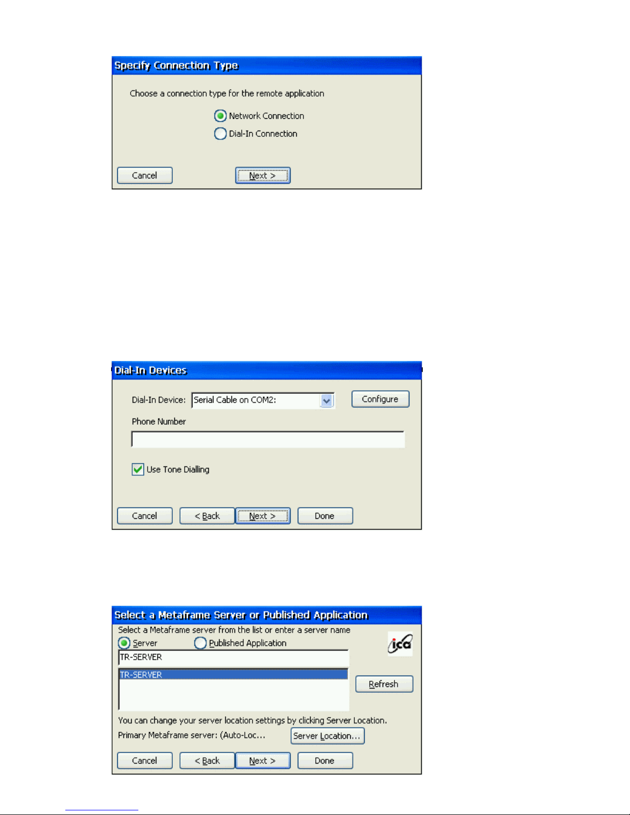
Click Network Connection to make a network connection. Make sure your client device
is connected to the network through the Ethernet connector. Click Next to continue. Skip
to Step 6.
—or—
Click Dial-In Connection to make a dial-in connection. Make sure your modem is
installed and properly configured. Click Next to continue.
Note :The ICA Windows CE Client does not support modem callback.
5. The Dial-In Devices page appears:
From the pull-down list, select your modem. In the Phone Number box, type the phone
number of the Citrix server including the area code and country code if required. Click
Next to continue. Skip to Step 9.
6. The Select a Metaframe Server or Published Application page appears:
Page 31
7. Click Server to connect to a server or Published Application to connect to a
published application. You can click Refresh button to refresh the Citrix server on
the network, then select the server which you want to connect to.
If your CE device is not on the same network as the Citrix server which you would
like to connect to, the server name will not appear in the list (this would occur if you
are on the other side of a router, across the Internet, or using RAS to connect to a
remote network containing Citrix servers). In this case, click Server Location and go
to the next step. Otherwise, scroll through the list and select the Citrix server or
published application or type the name of the Citrix server or published application in
the edit field. Click Next.
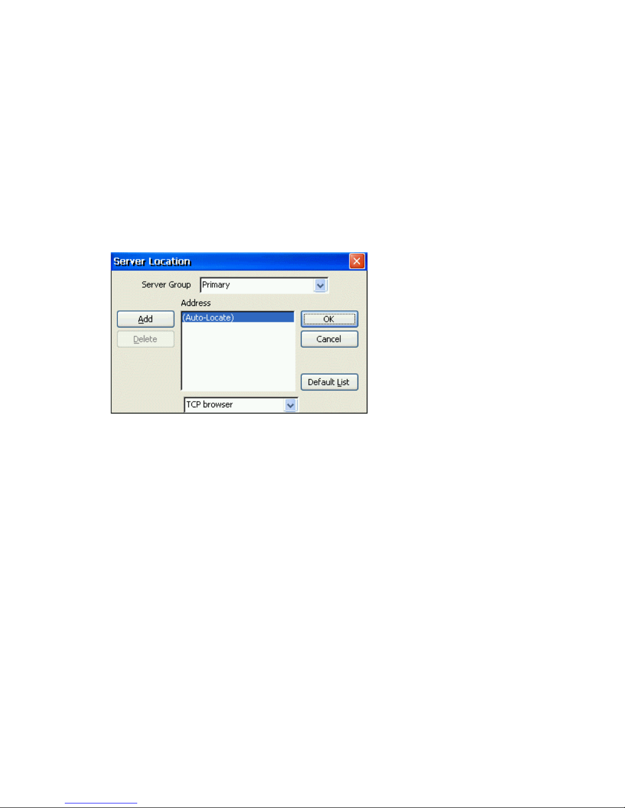
8. The Server Location dialog box appears:
Remote Application Manager uses the information entered in the Server Location screen
to help locate available Citrix servers and published applications.
If:
• you are on another network (for example, if you are on the other side of a
router, across the Internet, or connected by RAS), click Add to enter the
IP address or DNS name of a Citrix server on the network that contains the
Citrix server you would like to connect to. The Windows CE client uses
this server to locate the list of available Citrix servers on the network.
• your network configuration cannot propagate UDP traffic (for example, if
your firewall restricts UDP broadcasts), please select TCP + HTTP
browser or SSL/TLS + HTTPS browser. Make sure that the list contains
the IP address or name of a Citrix server on the network that contains the
Citrix server you would like to connect to. The Windows CE client uses
this server to locate the list of available Citrix servers on the network.
Note: When you first select TCP + HTTP browser, the convention used for the default
server name is ica.domainname where domainname is your TCP/IP domain name. You
can change this to a specific server name/IP address or leave the default setting and map
the name of a server to ica.domainname. Note that TCP/IP+HTTP server location uses a
TCP connection so does not support the (Auto-Locate) function.
Click OK and then click Next.
Page 32
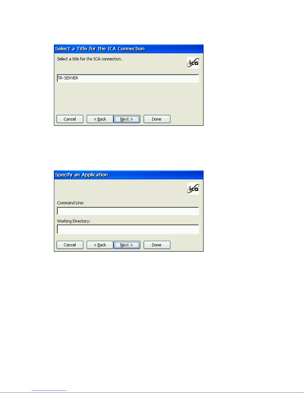
10. The Select a Title for the ICA Connection page appears:
Enter a name for the connection entry. The name you choose is the name of the
entry in the list of connections in Connection Manager. Click Next to continue.
11. The Specify an Application screen appears (this screen does not appear when
configuring a published application connection):
In the Command Line field, enter the path and name of an application to run on the server
once the logon to the Citrix server is successful. Leave this field blank to run a Windows
NT desktop on the Citrix server. Working Directory lets you associate a directory with
the application specified in the Command Line field. Enter the drive and path of the
working directory in the Working Directory field.
For example, if the application Notepad.exe is in the C:\WTSRV directory on the Citrix
server, type C:\WTSRV\Notepad.exe in the Command Line field. If you use Notepad to
work on documents in the C:\My Documents directory, type C:\My Documents in the
Working Directory field. When you log on to the Citrix server, Notepad begins. In
Notepad, if you click the File menu, the directory C:\My Documents is displayed. Click
Next to continue.
Page 33
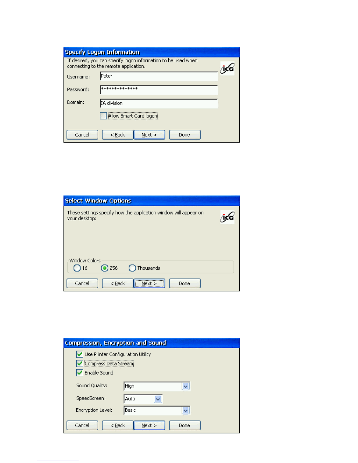
11. The Specify Logon Information screen appears:
Type a valid username, domain, and password. If you leave these fields blank, you are
prompted for your username, domain, and password when the ICA Windows CE Client
connects to the Citrix server. Click Next to continue.
12. The Select Window Options screen appears:
In the Window Colors field, you can set the number of colors used for the ICA Client
window. There is three ratio buttons, 16, 256 and Thousands. You can select one of them
and Click Next to continue.
13. The Compression, Encryption, and Sound screen appears:
Page 34

• Click Use Printer Configuration Utility to enable printer auto configuration.
• Click Compress Data Stream to reduce the amount of data transferred between the
ICA Windows CE Client and the Citrix server hosting the session. (If your connection
is bandwidth-limited, enabling compression may increase performance. If your client
device is on a high-speed LAN, you may not need compression.)
• Click Enable Sound to enable sound support. Remote applications will be able to
play sounds on your client. From the pull-down list, select a sound presentation
quality level. High provides the greatest audio quality but should only be used when
bandwidth consumption is not a concern. Medium results in less bandwidth
consumption than when using High. Compression of sound data provides greater
bandwidth efficiency but reduces sound quality somewhat. This value is
recommended for most LAN-based connections. Low offers the most efficient use of
bandwidth but also decreases sound quality severely. This value is recommended for
low-bandwidth connections, including most modem connections.
Speed Screen - SpeedScreen latency reduction improves responsiveness over high
latency connections by providing feedback to the user in response to typed data or mouse
clicks.
Note SpeedScreen will only work if the server-side SpeedScreen feature is available has
been enabled on the Citrix server to which you are connecting.
To change SpeedScreen latency reduction settings
1. In Connection Manager dialog box, select the connection entry that you
want to change.
2. Click the Options tab.
3. In the SpeedScreen field, select the setting (On, Off or Auto) you need.
• For slower connections (for example, if you are connecting over a
WAN or a dial-in connection), set mode to On to decrease the delay
between user input and screen display.
• For faster connections (for example, if you are connecting over a
LAN), set mode to Off.
• If you are not certain of the connection speed, set the mode to Auto to
turn SpeedScreen latency reduction on or off automatically depending
on the latency of the connection.
Encription Level - Encryption increases the security of your ICA connection. By
default, basic encryption is enabled on all connections. If the Citrix server you are
connecting to supports advanced encryption (e.g., SecureICA services), you can
use it to improve security.
To change the encryption settings for an ICA connection
4. In Connection Manager dialog box, select the connection entry you want
to configure.
5. In the Properties tab, click Options.
Page 35
6. Click Encryption and select the level of encryption you want to use. The
default level is Basic. Select RC5 128-bit Login Only to use encryption
only during authentication.
The Citrix server must be configured to allow the selected encryption level or
greater. For example, if the Citrix server is configured to allow RC5 56-bit
connections, the ICA client can connect with RC5 56 or 128-bit encryption.
Note To use advanced encryption, you need to install SecureICA on your Citrix
server. The Citrix server must also be configured to allow the selected
encryption level or greater.
Click Next to continue.
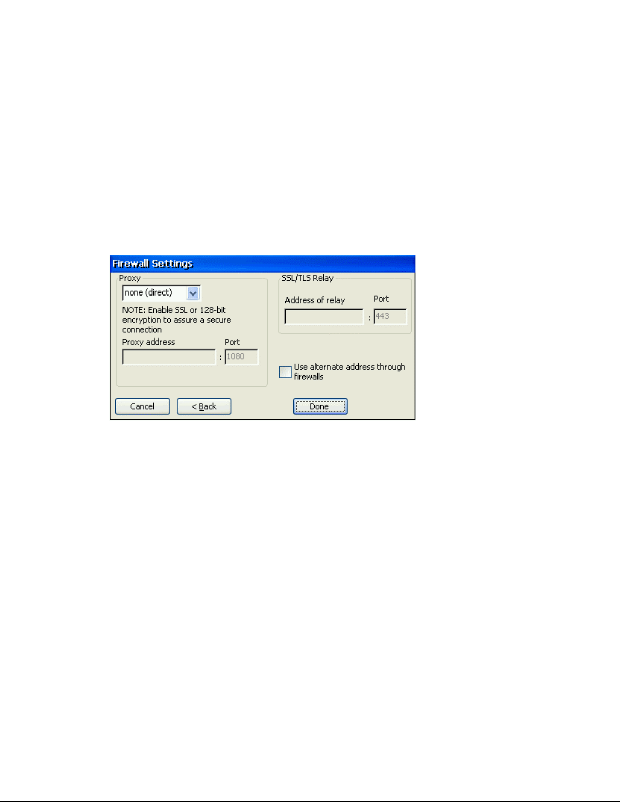
14. The Firewall Settings screen appears:
In the Firewall Settings dialog box, you can configure the client to use a SOCKS proxy
and alternate address remapping.
15. Click Finish to save the entry or Cancel to exit the new connection entry dialog box
without saving the entry.
Once you have created a connection entry, the name appears in the list of connections in
Connection Manager.
Page 36
Editing a Connection
Editing a Connection
The Edit button on Configure Dialog Box allows the user to edit or modify the properties of
selected connection.
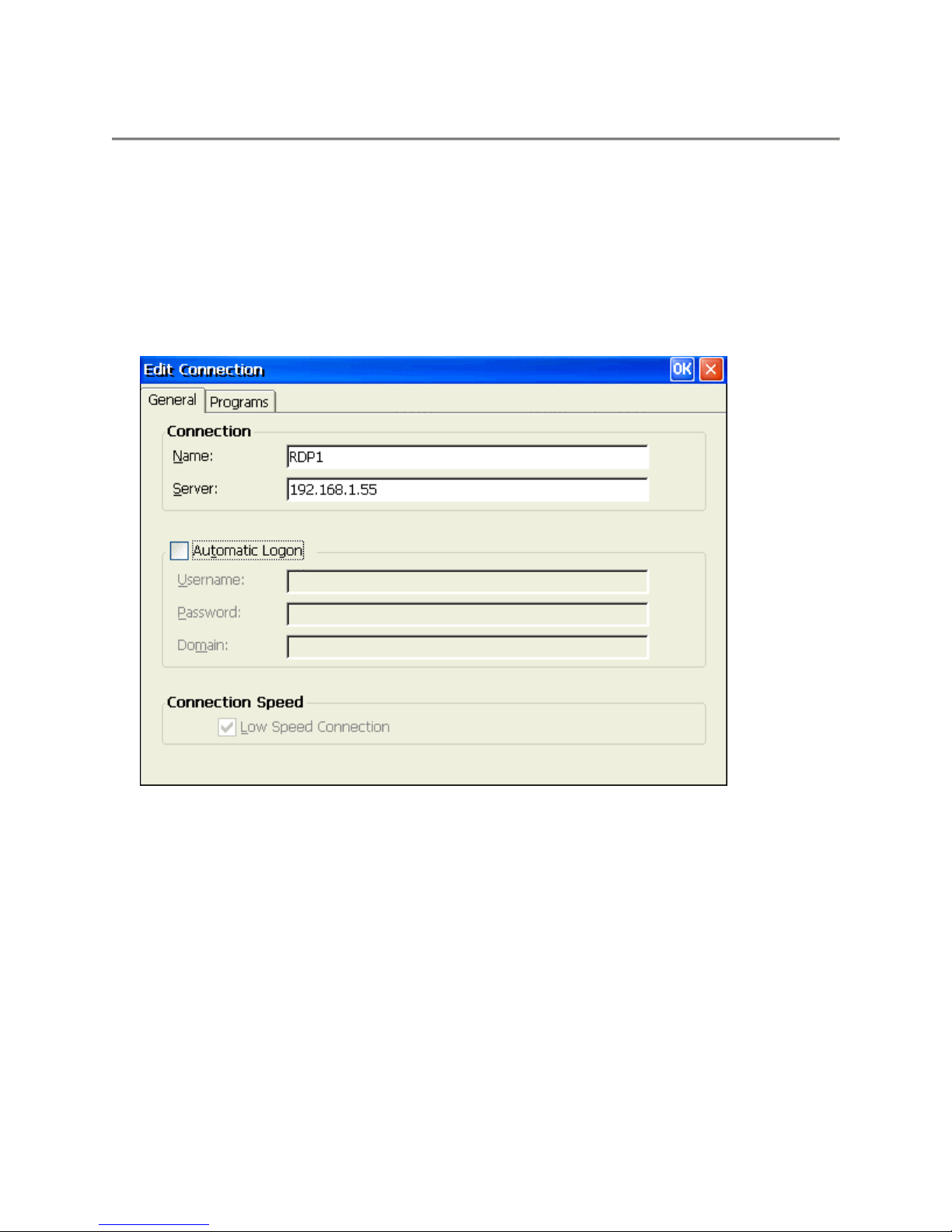
Editing a RDP Connection
There are two properties sheets on the Properties dialog box. Depending on your connection
configuration, you can use these two properties sheets to edit connection parameters.
Net Connections Tab
Name
This field displays a connection name listed in the Terminal Connection Manager. Enter
the name in this field and click OK button, you can change and save the connection name
of the selected server.
Server
This field displays the IP address or server name of the selected server.
Automatic Logon
Click this toggle button to enable/disable automatic logon. The Username, Password and
Domain fields will be enabled when the Automatic Logon is checked.
Username
Enter your user name for Automatic Logon check.
Password
Enter your password for Automatic Logon check.
Page 37
Domain
Enter your domain for Automatic Logon check.
OK
Click on OK button to save your changes and quit the dialog box
Cancel
Click on Cancel button to quit the dialog box without any change.
Apply
Click on Apply button to use the changes.
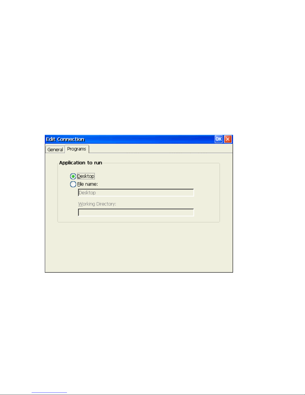
Application Tab
Using the Application Properties Sheet, you can designate an application program on the
server to run automatically when the connection is made.
Desktop
Click on Desktop button to select a desktop application to run.
File Name
Click on File name button to select a file to run. Enter the file name of the application in
the field provided.
Working Directory
Enter the directory path of the application file provided in File Name.
OK
Click on OK button to save your changes and quit the dialog box
Cancel
Click on Cancel button to quit the dialog box without any change.
Page 38
Apply
Click on Apply button to use the changes.
Editing an ICA Connection
There are seven dialog boxes that display in succession during the editing process. Please follow
the instructions on the screen to complete all fields editing step by step. (Note: For more detail
introduction, please refer to the
To change the properties of a connection entry
1. In the Connection Manager dialog box, click the Configure tab.
2. Click the name of the connection entry that you want to change.
3. Click Edit to display the Edit Connection Details dialog box.
ICA Administrator's Guide.pdf
4. Make the desired changes.
5. Click OK to save your changes.
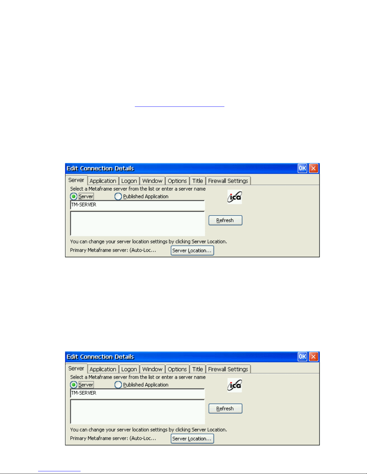
The Edit Connection Details dialog box contains the following tabs:
• The Server tab (network connection entries only), where you can set the server or
published application name to which to connect. There is also a button to display
the Server Location dialog box where you can set Business Recovery options.
Page 39
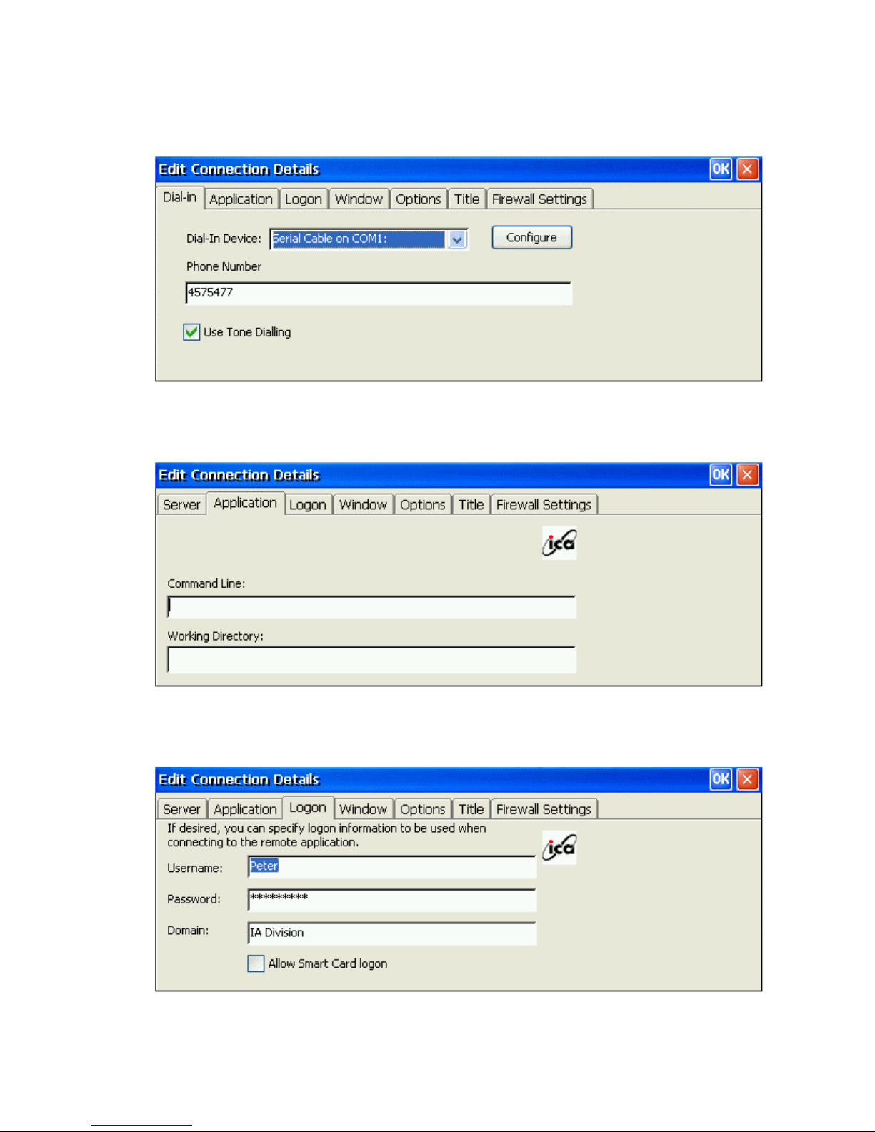
• The Dial-in tab (dial-in connection entries only), where you can set the area code,
country code, and telephone number to dial. You can use the settings on this page
in the same way as when you first set up the connection entry.
• The Application tab, where you can specify an application to run after connecting
to a Citrix server.
• The Logon tab, where you can set the user name, password, and domain to use to
log in to the Citrix server automatically.
Page 40
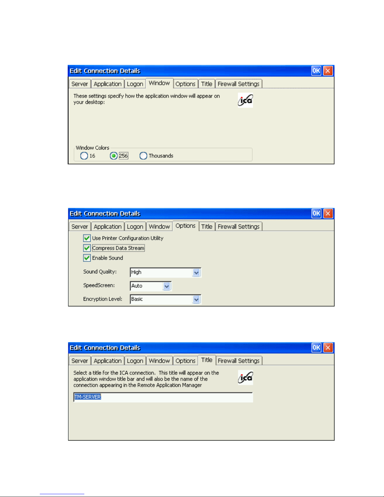
• The Window tab, where you can set the number of colors used for the ICA Client
window.
• The Options tab, where you can control the connection between the Citrix server
and Windows CE device, such as ICA virtual printer, ICA data stream
compression option, sound quality, encryption level.
• The Title tab, where you can change the name of the connection. The name
appears in the list in the Connection Manager dialog box.
Page 41
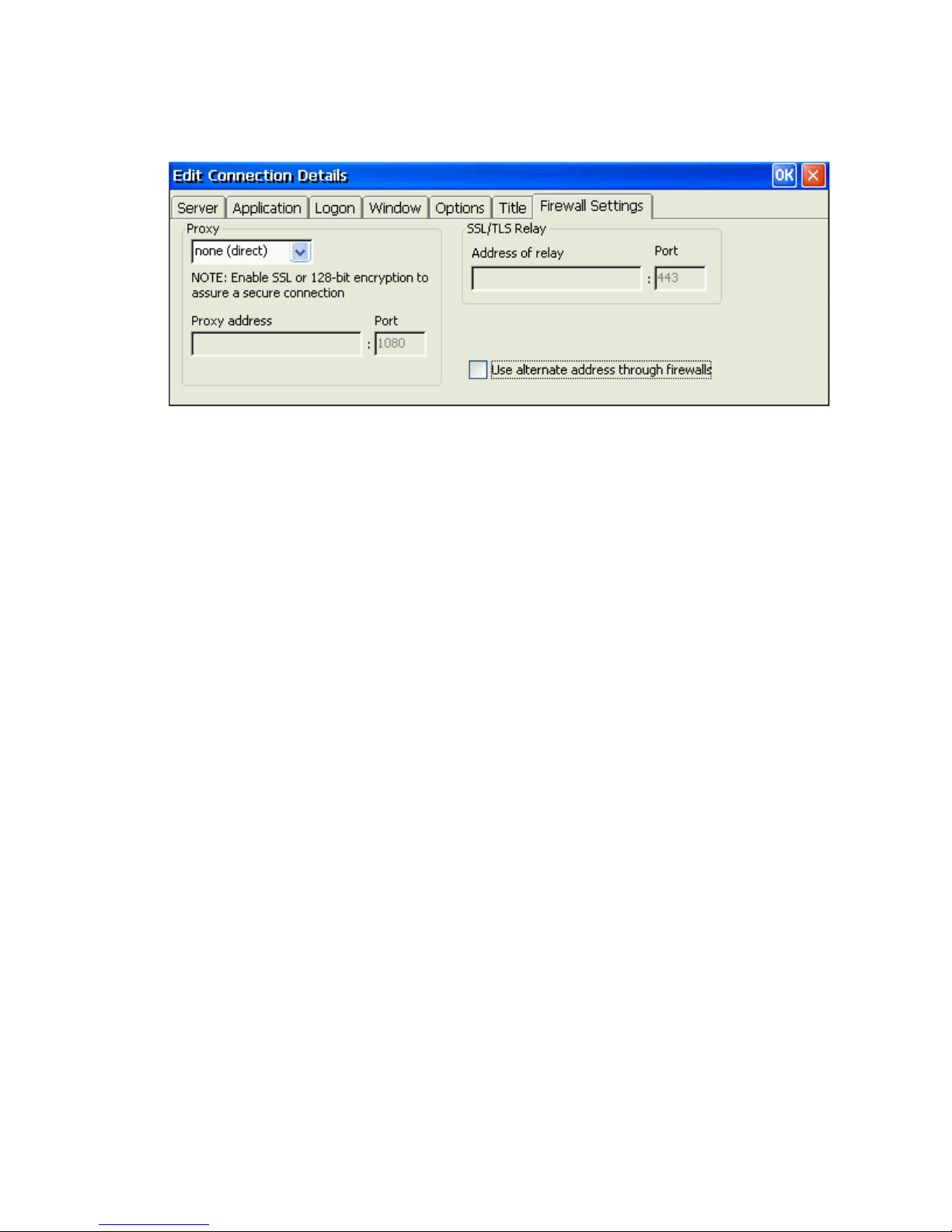
• The Firewall Settings tab, where you can configure the client to use a SOCKS
proxy and alternate address remapping.
Page 42
General Settings and Information
Starting Programs
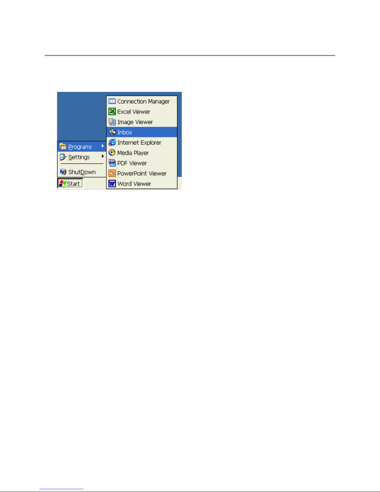
Start Menu Window
To open a program that isn’t on the desktop, select Start > Programs > program name from
the Start menu on the desktop.
Starting Multiple Sessions
From a working session or another application (i.e. “Inbox”), invoke the Terminal
Connection Manager by clicking on the desktop icon or selecting Start > Programs >
Connection Manager from the Start menu. Then click on another connection to start a new
session.
Arrange Desktop Icons
To have the system automatically arrange the desktop icons, place the mouse in an open area
of the desktop.
1. Click the right mouse button. This is the same as pressing the ALT key and left click
with the mouse.
2. Select and highlight the Arrange Icons selection.
3. Select the method for which you want to arrange the icons from the list.
Move Desktop Icons
1. Place mouse over a desktop icon and hold down the left mouse button.
2. Drag the icon to the desired place on the desktop and release the mouse button.
Note: These changes are not saved on reboot.
Toggle or Switch between Sessions and / or Windows
To switch between active sessions or application windows, you have 3 choices:
• Select the appropriate window from the MinIT6000 taskbar.
Page 43
• Hit the <ALT> and <TAB> keys at the same time to bring up the Task Manager window,
select the appropriate Active Task and then select the Switch To button.
• Hit the <ALT> and <ESC> keys at the same time to toggle between all of the active
windows.
Jump to Desktop from Session or Application Window
From any session or application window, it is possible to jump directly to the CE desktop.
Just select the “Desktop” icon from the far right corner of the taskbar.
Change Taskbar Settings
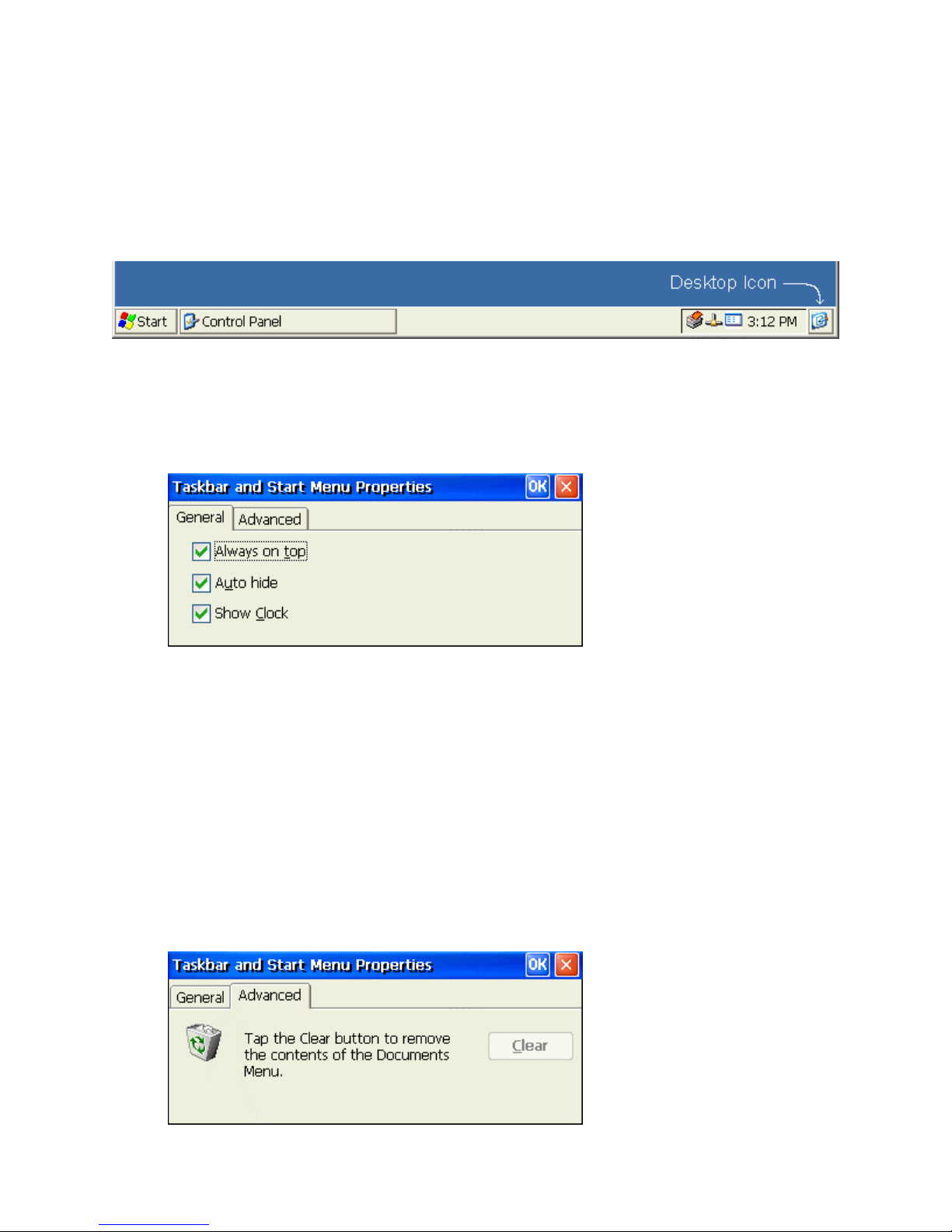
1. Select Start > Settings > Taskbar or move the mouse over the taskbar and click the
right mouse button to bring up the “Properties” window.
2. Under the taskbar General tab, place a check mark in the appropriate check box to enable
the following options:
Always on Top
When this function is enabled (default), the taskbar will remain visible with all other
windows open except an RDP session. See Multiple Taskbars.
Auto Hide
When this function is enabled, the taskbar hides away when the mouse is removed from
the bottom of the screen.
Show Clock
When this function is enabled (default), the clock appears on the right side of the taskbar.
3. To clear the contents of the Documents Menu, select the Advanced tab.
4. Click on the Clear button.
Page 44
5. Click on the OK button to close the Taskbar Properties window.
Multiple Taskbars
When running an ICA or RDP session, you will have access to the server taskbar within the
client session as well as the MinIT6000 desktop taskbar.
Depending on how each of them is setup, you may or may not have access to or know how to
get to the correct one. The following describes different options that might cause some
confusion.
MinIT6000 Desktop Taskbar
RDP window Taskbar
With this configuration, you will be unable to get to the RDP session taskbar because it gets
hidden behind the MinIT6000 taskbar. In this case the MinIT6000 taskbar acts as if it is set
to Auto hide even though it is set with Always on Top enabled. The solution is to disable
the Always on Top option for the MinIT6000 taskbar. To do this, move the mouse down to
the bottom of the screen to display the MinIT6000 task. Click the right mouse button and
select Properties to bring up the Taskbar properties window. Un-select Always on Top and
click OK. Now you should have access the RDP session taskbar. To get back to the
MinIT6000 taskbar, <ALT> and <TAB> keys at the same time to bring up the Task Manager
window as well as the desktop taskbar.
MinIT6000 Desktop Taskbar
RDP/ICA window Taskbar
Once the client session window is open, the problem with this configuration is that you will
not have direct access to the MinIT6000 desktop taskbar. To gain full access to the
MinIT6000 taskbar, the only solution to this is to close down the client session. However, to
switch to another active MinIT6000 window, hit the <ALT> and <TAB> keys at the same
time to bring up the Task Manager window. If you are in an RDP session window the
desktop taskbar will appear as well. To switch windows, select the appropriate active task
and click on the Switch To button. Note, you can also hit the <ALT> and <ESC> keys at the
same time to toggle between windows.
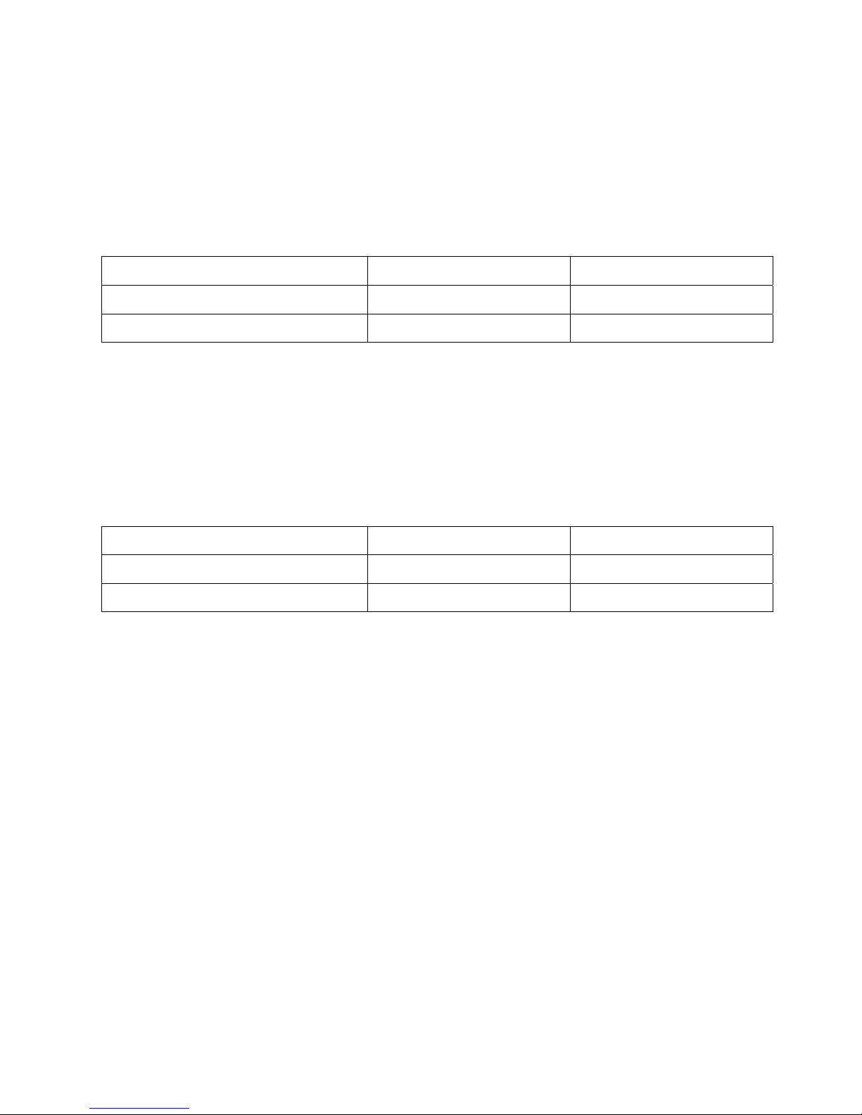
Always on Top Auto hide
Enabled Don’t care
Disabled Enabled
Always on Top Auto hide
Disabled Disabled
Don’t care Don’t care
Page 45
Configure Terminal Properties
Control Panel
Similar to a PC, all of the terminal settings can be done through the control panel.
Bringing up the Control Panel
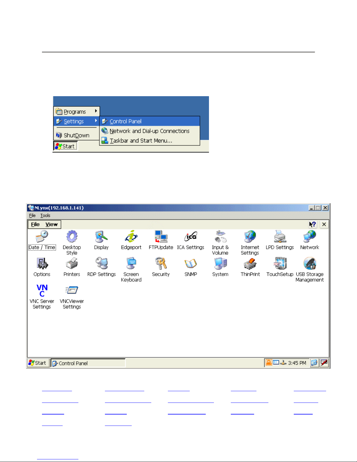
To bring up the Control Panel, select Start > Settings > Control Panel from the Start menu
on the desktop.
Control Panel Window
Date/Time Desktop Style Display Edgeport FTPUpdate
ICA Settings Input & Volume Internet Settings LPD Settings Network
Options Printers RDP Settings Security SNMP
System ThinPrint
Page 46
Date / Time
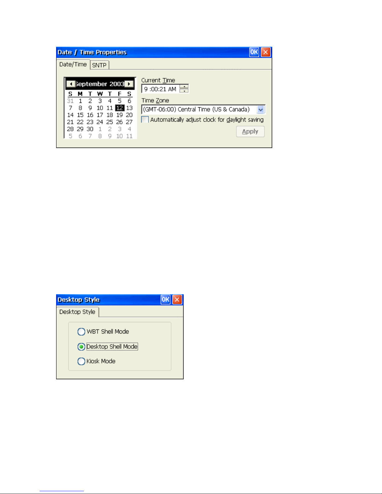
1. Click on the Date / Time icon to bring up the properties window.
2. To set the month, select the arrows on either side of the month shown to step through the
months, or select the month label to choose from a list of months.
3. To set the year, click on the year label to open an editing box and type in the correct year.
4. To set the date, select it in the calendar.
5. To change the time, enter it in the Current Time box, type in the correct time or click on
the up/down tabs to select the correct time. Click in the Time Zone box and then use the
mouse or the up/down arrow keys to select the appropriate time zone. Place a check in
the Daylight Savings check box if it applies. Finish by clicking on the Apply button or
selecting OK for your setting to take effect.
Note: You can also enter the Date/Time setup window by clicking on the time
indicator on the taskbar (lower right hand corner of the screen).
Desktop Style
WBT Shell Mode
Selecting this option only allows the user to view the client options through the
"Terminal Connection Manager" window only. To launch the email client in this mode,
the user must choose the "Configure" tab and select "Add" each time.
Desktop Shell Mode
Selecting this option allows the user to view the client options and additional applications
through a standard "Windows" looking interface with the ability to select ones own
background wallpaper. This mode is set by default.
Page 47
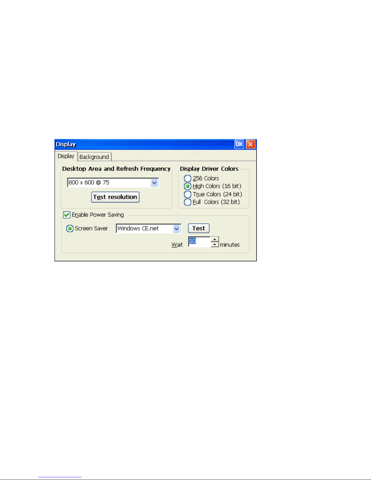
Kiosk Mode
Selecting this option only allows the user to view a browser window that has been
pointed at a specific web page. The normal Internet browser address window is not
displayed. This mode is intended for company "Intranet" applications. Once selected, to
get out of Kiosk mode, select <CTRL> <ALT> <UP>.
Note: Changing modes forces the unit to be re-booted with all current client
configurations being deleted.
Display
Use the Display properties window to configure the terminal's display screen.
Display Tab
The following table discusses the functions of this properties sheet.
Desktop Area and Refresh Frequency
1. Use the pull-down list to select the terminal display resolution.
2. Use Test resolution button to preview the resolution selected to verify that your
monitor supports it.
Enable Power Saving
Click on the check box to enable the power saving features. This is set by default.
Screen Saver
1. Click on this ratio button to enable the screen saver. This is set by default.
2. Choose from one of two screen saver patterns, Windows CE logo and blank screen.
3. Adjust the amount of time before the screen saver becomes active.
4. Use the Test button to preview the Screen Saver image for 3 seconds.
Display Driver Colors
Select the hardware display color setting. High Color (16 bit) is set by default. If you
encounter any display problem within an application, try choosing the 256 colors setting
to see if it resolves the problem. Selecting the True Color or Full color options will give
you higher image quality but may slightly reduce system performance (speed).
Page 48
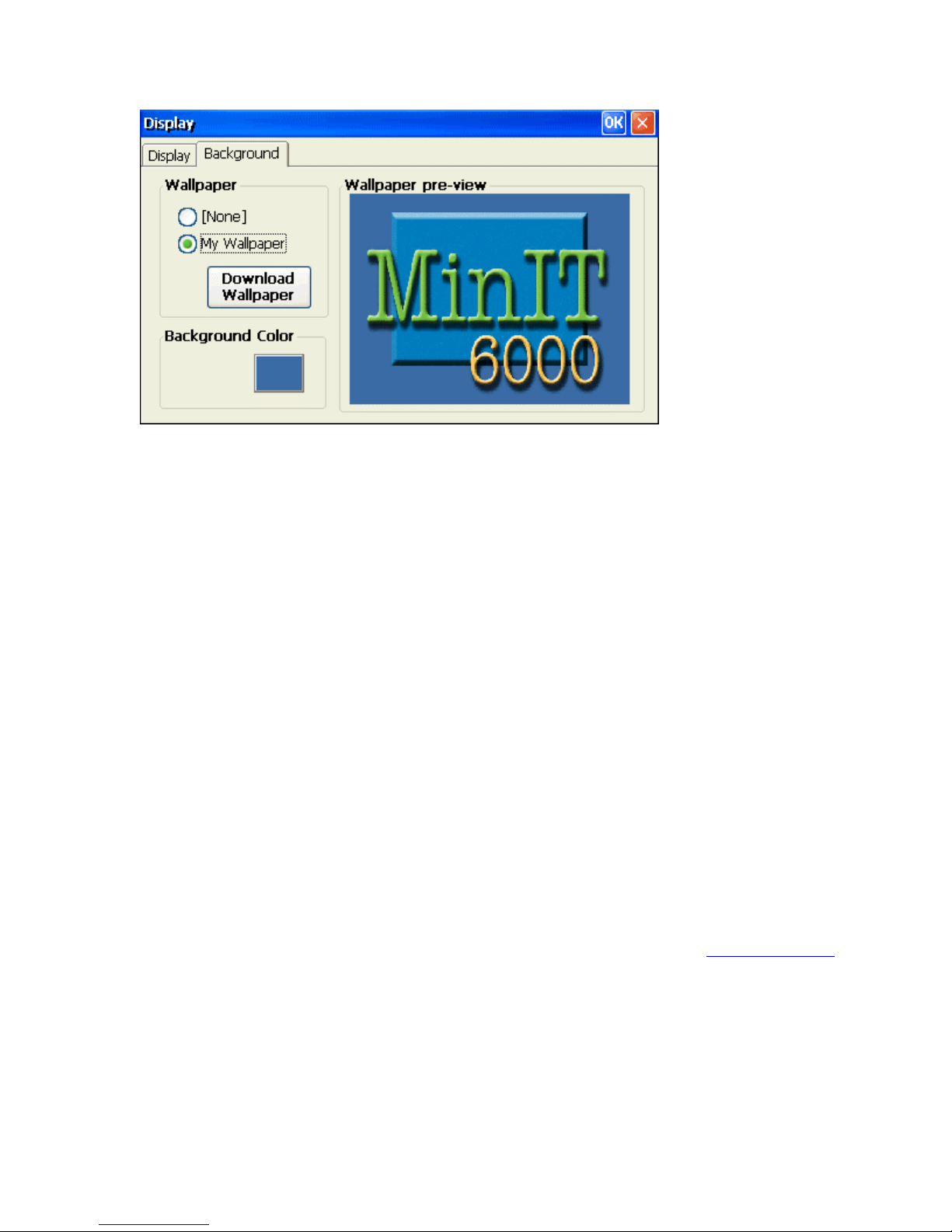
Background Tab
Wallpaper
You may choose to download and select your own desktop wallpaper. The unit by
default is loaded with the "MinIT 6000" background wallpaper. To install and use your
own (must be a BMP image), click on Download Wallpaper to bring up the "FTP
Update window". Enter in the appropriate FTP information and then type in the file
name (i.e. image.bmp) of your background image. For more information, see the FTP
Update section.
Background Color
The Background Color is the color of the screen displayed when no (None) wallpaper has
been chosen. If a wallpaper has been chosen, depending on the image size, the
background color is used to fill up the screen surrounding the wallpaper image.
1. To select the desktop background color, click on the color square. This brings up the
color pallet window.
2. Choose from the available colors.
3. Click on OK.
Wallpaper pre-view
The pre-view window shows the current wallpaper installed on the MinIT6000 unit.
Note: Only one wallpaper image can be installed at a time.
FTP Update
Use FTP Update to download updated MinIT6000 firmware (i.e. software in ROM) or
Desktop Background images. For more information, please refer to the
section.
Upgrade Utilities
Edgeport
Edgeport USB-to-Serial Converters offer an easy Plug-and-Play solution for instant COM port
expansion. The Edgeport connects directly to the USB port of the MinIT6000. To allow for
flexibility, the Edgeport is available with a wide variety of options to meet specific application
requirements. Edgeport adapters are available from Inside Out Networks.
Page 49
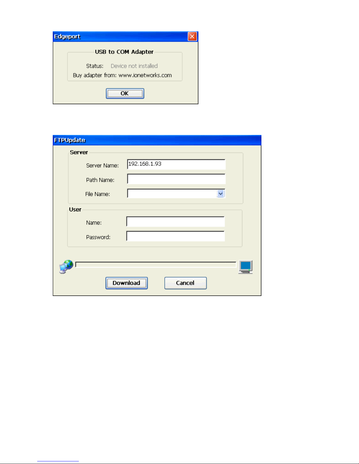
FTP Update Window
1. Enter in the name or IP address of the FTP server that contains the updated firmware
(or bmp image for backgrounds).
2. Type in the directory path where the file is located.
3. Type in the full file name of the updated firmware or click on the pull down menu
and select the file from the list.
4. Type in the User Name and Password required to log into your FTP server.
Note: Most FTP servers are case sensitive in regards to the path and file name information.
5. Click on Download.
Page 50
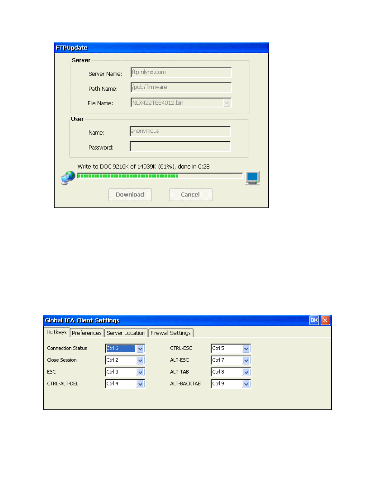
Download Process Information Box
During the download process, the system will show you the progress. The unit downloads
the file into memory and verifies it's integrity before it copies it into flash. The download
time will vary depending on the speed of the network and FTP server as well as the file size.
ICA Setting
The global settings are accessed from the Global ICA Client Settings properties window. This is
usually accessed with other Terminal property settings on your terminal. The key combination
used to display the properties will be in the documentation supplied by your Windows CE
terminal manufacturer. It is usually a function key such as F2.
Hotkeys Tab
1. Open the Global ICA Client Settings dialog box according to the instructions for your
Windows-based terminal device.
2. Make the desired changes.
3. Click OK to save your changes.
Page 51
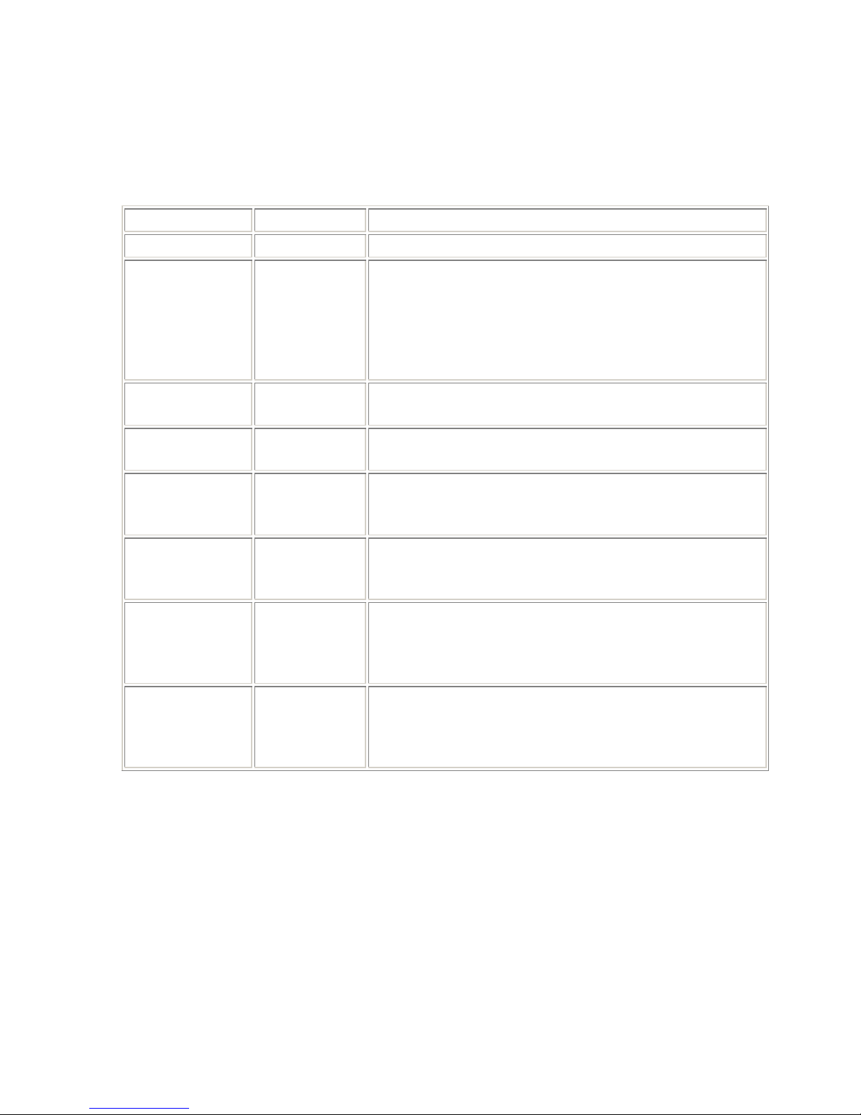
Configuring Hotkeys
The ICA Windows CE Client provides users with hotkeys that can be used during ICA
sessions to control various functions. Some hotkeys control the behavior of the ICA
Windows CE Client itself while others emulate standard Windows hotkeys. When you
want to use a Microsoft Windows key combination during a session, use the mapped
hotkey instead. The following table lists the default ICA Windows CE Client hotkeys.
Name Default Value Description
Status Dialog CTRL+6 Displays ICA Client connection status.
Disconnects the ICA Windows CE Client from the Citrix
server and closes the client window on the local desktop.
Close Session CTRL+2
Using this hotkey leaves the ICA session running in a
disconnected state on the Citrix server. If you do not want
to leave your session running in a disconnected state, log
off instead.
Esc CTRL+3
CTRL-ALT-DEL CTRL+4
Provides the functionality of an ESC key on your
terminal.
Displays the Windows NT Security dialog box on a
MetaFrame for Windows server.
On MetaFrame for Windows servers, the Windows
CTRL-ESC CTRL+5
menu is displayed. On
Task List.
This hotkey cycles the focus through the minimized icons
ALT-ESC CTRL+7
and open windows of applications run in your ICA
session
This hotkey cycles through all applications in the ICA
ALT-TAB CTRL+8
session. A pop-up box appears and displays the programs
as you cycle through them. The selected application
receives keyboard and mouse focus.
Like the ALT+TAB hotkey, this key sequence cycles
ALT-BACKTAB CTRL+9
through applications that have been opened in the ICA
session, but in the opposite direction. The chosen
application receives keyboard and mouse focus.
To change the default hotkeys:
Start
WINFRAME servers, this hotkey displays the
1. Use the list of keys to customize the default hotkey key sequences.
2. Click OK to save the settings.
Page 52
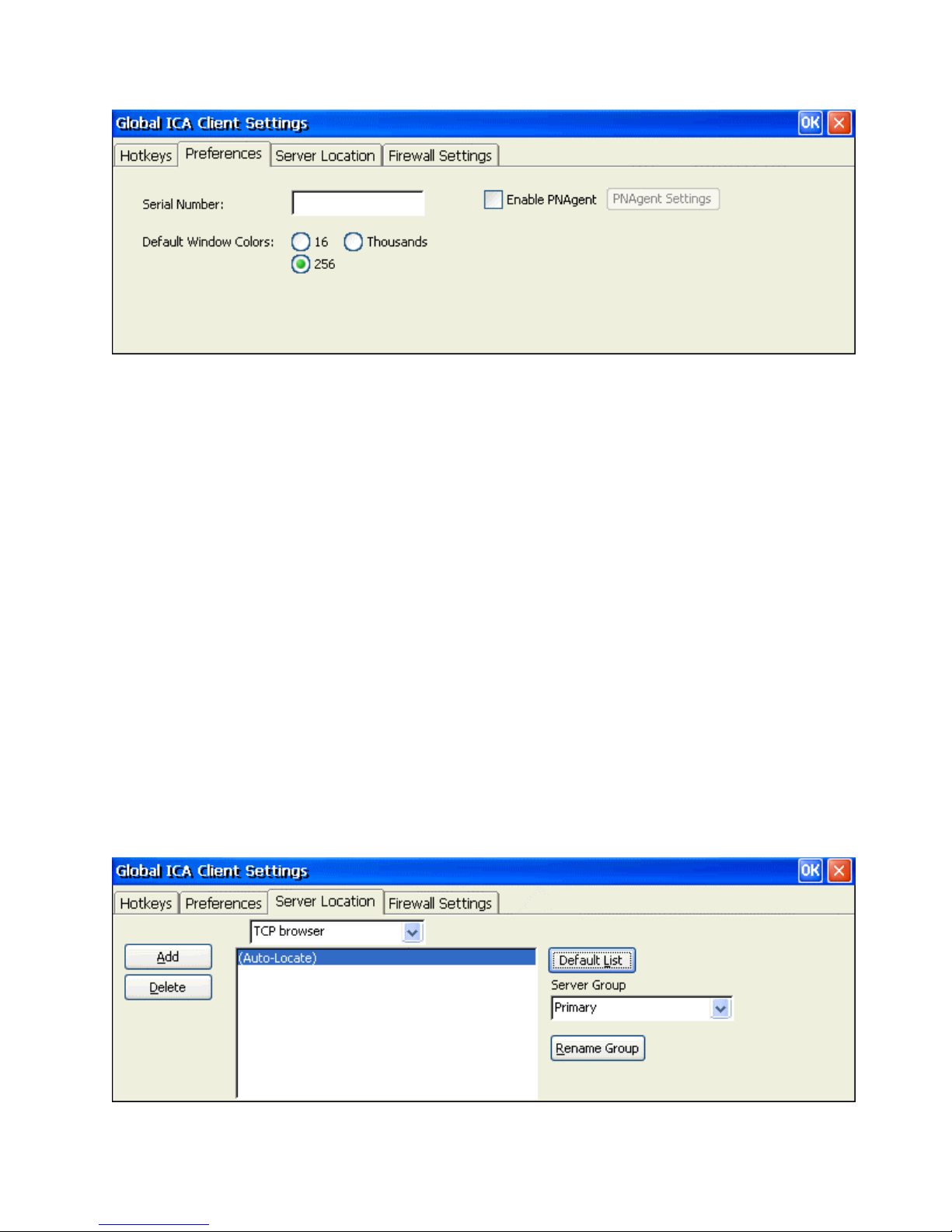
Preferences Tab
Serial Number
This is the serial number of your ICA Client software. This number is only necessary
when you are using the ICA Windows CE Client with a product such as
WINFRAME
Host/Terminal, which requires each ICA Client to have a Citrix PC Client Pack serial
number. If a serial number is required, you must enter it exactly as it appears on the
Serial Number card. The serial number is not used when connecting to MetaFrame
servers.
Default Window Colors
In the Window Colors box, select the color depth you require. When using a PPP
connection, 16 color mode may provide better performance. If the window options
specified exceed the capabilities of the client hardware, the maximum color depth
supported by the Windows CE device are used instead.
Note: The options to select Thousands or Millions of colors are not available if
your device is not capable of high color display.
Enable PNAgent
Click on the check box to enable PNAgent mode. In PNLite mode, a list of available
published applications on the network is "pushed" to the ICA client and displayed in the
Connection Manager dialog box.
Server Location Tab
Page 53
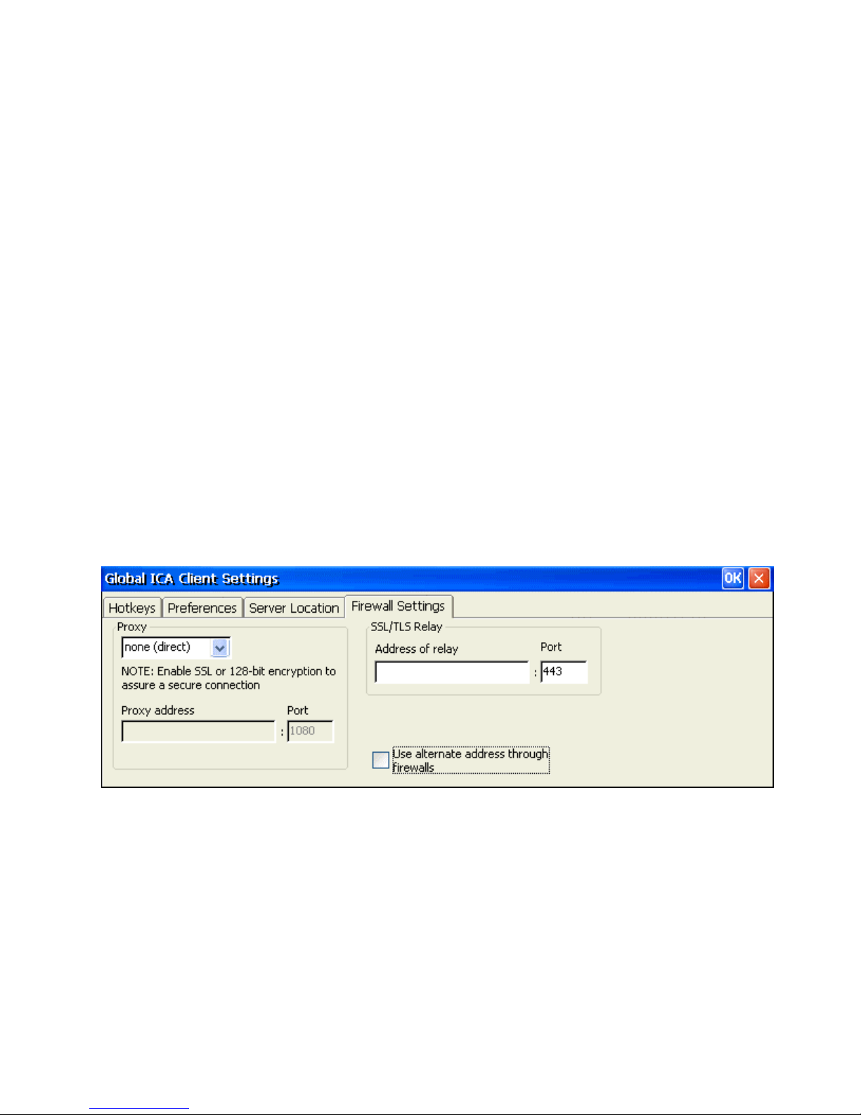
Server location (also called server browsing) provides a method for a user at a network-
connected Citrix ICA client to view a list of all Citrix servers on the network, and a list of all
published applications.
Tip: Set a specific server address for the Citrix server that functions as the master ICA
Browser when your network configuration uses routers or gateways, or to eliminate
broadcasts on your network. Business recovery provides consistent connections to published
applications in the event of a master ICA Browser server disruption. You can define up to
three groups of Citrix servers to which you want to connect: a primary and two backups.
Each group can contain from one to five servers. When you specify a server group for your
client, the client attempts to contact all the servers within that group simultaneously, and the
first server to respond is the one to which you connect.
1. Using the pull-down list, select the browser type.
2. In the Server Group field, select the group that you want to configure. The Server
Group field lets you create lists of specific servers that you want to designate as
primary and backup servers for connecting to published applications. Use this
field to designate whether the servers entered in the Address List field belong to
your Primary, first backup (Backup 1), or second backup (Backup 2) group.
3. Click the Add button to add a server to the selected group. The Add Server
Address dialog box appears.
4. Enter the name or address of a Citrix server and click OK.
5. Add more servers as necessary and then click OK to save the changes.
Firewall Settings Tab
Configuring the ICA Client to Use a SOCKS Proxy
If you are using a SOCKS proxy server to limit access to your Citrix servers, you must
configure a SOCKS proxy server to handle connections between clients and the server. You
can place the proxy server on either side of the firewall, or in some situations, on both sides
of the firewall.
If your network is using a SOCKS proxy server, you must configure the ICA Client to
connect to Citrix servers through it. You can configure a default SOCKS proxy for all
connections or a SOCKS proxy with a specific connection entry.
To configure a default SOCKS proxy server:
1. Click on the Proxy pull-down list and select SOCKS.
2. In the Proxy address box, type in the proxy server's IP address or DNS name.
Page 54

3. In the Port box, type in the proxy servers port address if it is different than 1080
(default).
4. Click OK to save the changes.
Note: If you configure a default SOCKS proxy, you must specify at least one server
in the Server Location tab for server and published application browsing to work.
To configure a SOCKS proxy for a specific connection entry:
1. Click on the Proxy pull-down list and select SOCKS.
2. In the Proxy address box, type in the proxy server's IP address or DNS name.
3. In the Port box, type in the proxy servers port address if it is different than 1080 (default).
4. Click OK to save the changes.
To configure a SOCKS proxy for a specific ICA client connection:
1. From the "Connection Manager" window, select the ICA client connection you
want to change.
2. Click on the Edit button to bring up the "Edit Connections" window.
3. Click on the Firewall Settings tab.
4. Follow the instructions for the procedure above beginning with Step 1.
Configuring Alternate Address Translation:
If the ICA Client is outside a firewall that uses address remapping, you must configure the
ICA Client to use the alternate address returned by the master ICA Browser. This is
necessary even if you are not using a SOCKS proxy server.
Note: You must also use the ALTADDR utility to manually set the alternate address
for each Citrix server. See the Command Reference appendix of either the
MetaFrame Administrator's Guide or the
WINFRAME System Guide for more
information.
To use alternate address translation for all connection entries:
1. Open the Global ICA Client Settings dialog box.
2. Click the Firewall Settings tab.
3. Click Use alternate address for firewall connection.
4. Click OK to save your changes.
Note: If you set alternate address translation for all connection entries, it cannot be
disabled for specific connection entries.
To use alternate address translation for a specific connection entry:
1. From the "Connection Manager" window, select the ICA client connection you
want to change.
2. Click on the Edit button to bring up the "Edit Connections" window.
3. Click the Firewall Settings tab.
4. Click Use alternate address for firewall connection. Click OK to save your changes.
Page 55
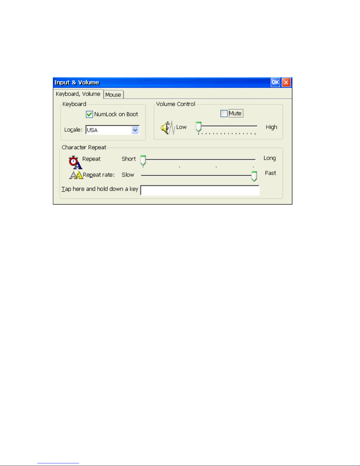
Input & Volume
Using the Input & Volume properties window to configure your terminal's keyboard, mouse and
audio volume.
Keyboard, Volume Tab
NumLock on Boot
Using the check box, you can enable NumLock while the terminal starts up.
Locale
Using the scroll list, you can select a language for the keyboard.
Volume Control
Using this slider control, you can adjust the volume of the audio and using the Mute
check box, you can disable the audio of the terminal.
Character Repeat
Using the slider control, you can adjust the repeat delay of keyboard characters. Repeat
defines how soon the same character will appear again when typed more than once.
Repeat Rate
Using this slider control, you can adjust the repeat rate of a keyboard character. Repeat
Rate defines how quickly the same character will appear again when a key is held down.
Tap here and hold down a key
Use this entry box to test the new settings.
OK
Click on OK button to save changes and quit the dialog box. Click on the X button to
quit the dialog box without saving changes.
Page 56
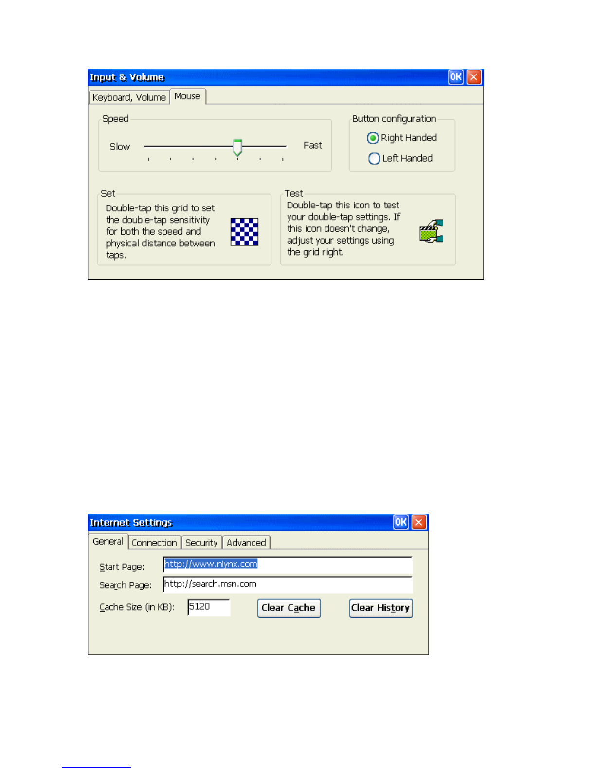
Mouse Tab
Speed
Using the slider control, you can adjust the mouse speed. Speed defines how much
distance will be changed for each mouse event.
Button Configuration
Using the ratio button, you can select Right Handed and Left Handed for your
convenience.
OK
Click on OK button to save changes and quit the dialog box. Click on the X button to
quit the dialog box without saving changes.
Internet Settings
Use the Internet Settings properties window to configure your Web browser settings
General Tab
1. Type in the desired URL to change the browser Start Page.
2. Type in the desired URL to change the browser Search Page.
3. Increase or decrease the memory space devoted to caching by typing in the new
larger or smaller value.
Page 57
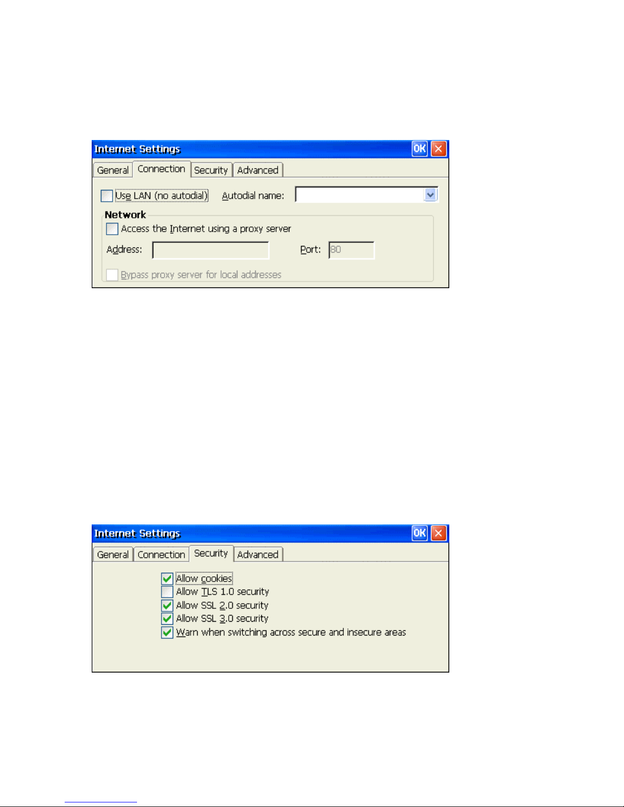
4. Click on the Clear Cache button to remove previous viewed web pages out of
memory.
5. Click on the Clear History button to remove any history of previously viewed
web pages.
Connection Tab
1. Click on the Use LAN check box if you plan to connect to the internet via the
Ethernet LAN.
2. If you are using a dial-up (serial port modem) connection, from the pull-down list,
select an Autodial name of the remote connection that you are planning on using.
Proxy servers are often used when connecting to the Internet through a local network, such as
a corporate network, for added security.
3. Click on the Access the Internet using a proxy server check box if this is correct.
4. Type in the proxy servers IP Address or DNS name.
5. Type in the access Port number if it is something other than the default of 80.
6. If you don't need the proxy server to access local IP addresses, click on the Bypass proxy
server for local addresses check box.
Security Tab
Use these options to select the level security that you want to determine what type of web
pages can be viewed. Enabling the Allow cookies option will allow cookies to be copied
into memory.
Page 58
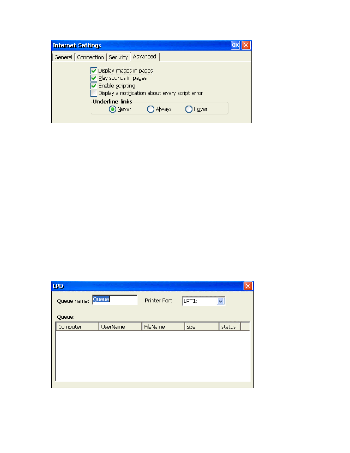
Advanced Tab
It is possible to speed up how fast the system renders web pages by "NOT" enabling certain
options. Choosing not to display images or play sounds could possibly increase the speed at
which the standard web page text is displayed.
Underline Links
Select how you want "Links" that are embedded within a given web page are displayed
by choosing the appropriate radio button.
LPD Setting
The Berkeley versions of the Unix(tm) operating system provide line printer spooling with a
collection of programs: lpr (assign to queue), lpq (display the queue), lprm (remove from queue),
and lpc (control the queue). These programs interact with an autonomous process called the line
printer daemon.
LPR is a TCP-based protocol. The port on which a line printer daemon listens is 515. The
terminal includes a LPD module, which allows an LPR device to print data from the local printer
of the terminal.
LPD Properties Window
1. Type in the Queue name of the LPD printer.
2. Select the Printer Port from the drop-down list.
Page 59
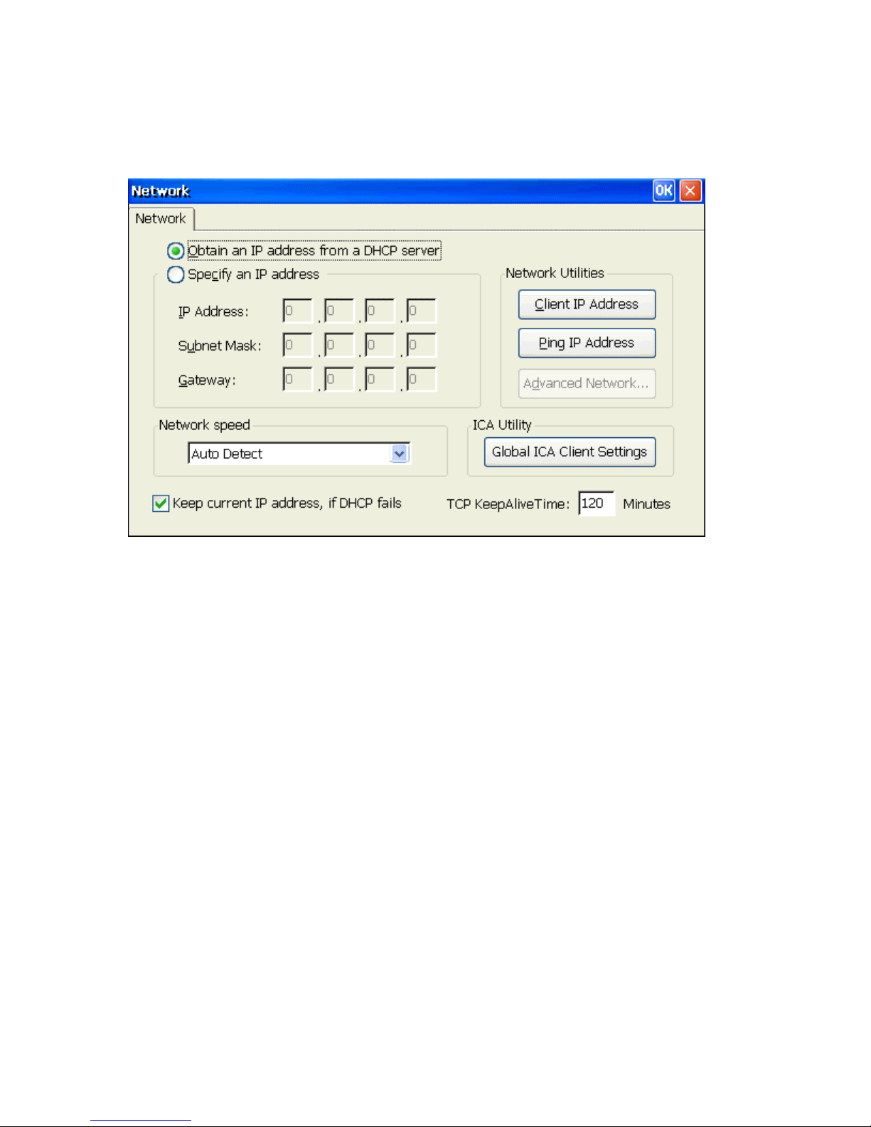
Network
The Network Setting Dialog Box lets you ether to enable a DHCP addressing or to specify an IP
address.
Network Properties Window
Obtain an Address from a DHCP Server
Click on this radio button to enable DHCP so you can obtain an IP address automatically
from a DHCP (Dynamic Host Configuration Protocol) server. This allows the network to
configure the TCP/IP information for your device.
Specify an IP Address
Click on this radio button to enable the following three fields for manually setting the
TCP/IP information for your device.
IP Address
Enter a static IP address in this field. It defines the IP address of the terminal, which
uniquely identifies it on a TCP/IP network
Subnet Mask
Enter the subnet mask of the IP address. This determines which part of the address
denotes the network.
Gateway
Enter in the IP address of the Gateway. If a host session address is outside of the Subnet
of the terminal, the Gateway address defines which gateway is used to reach the host.
Client IP Address
Click on the Client IP Address check button to show the Client information, including
Client name, IP address, subnet mask, gateway, DHCP server, DNS and WINS.
Page 60
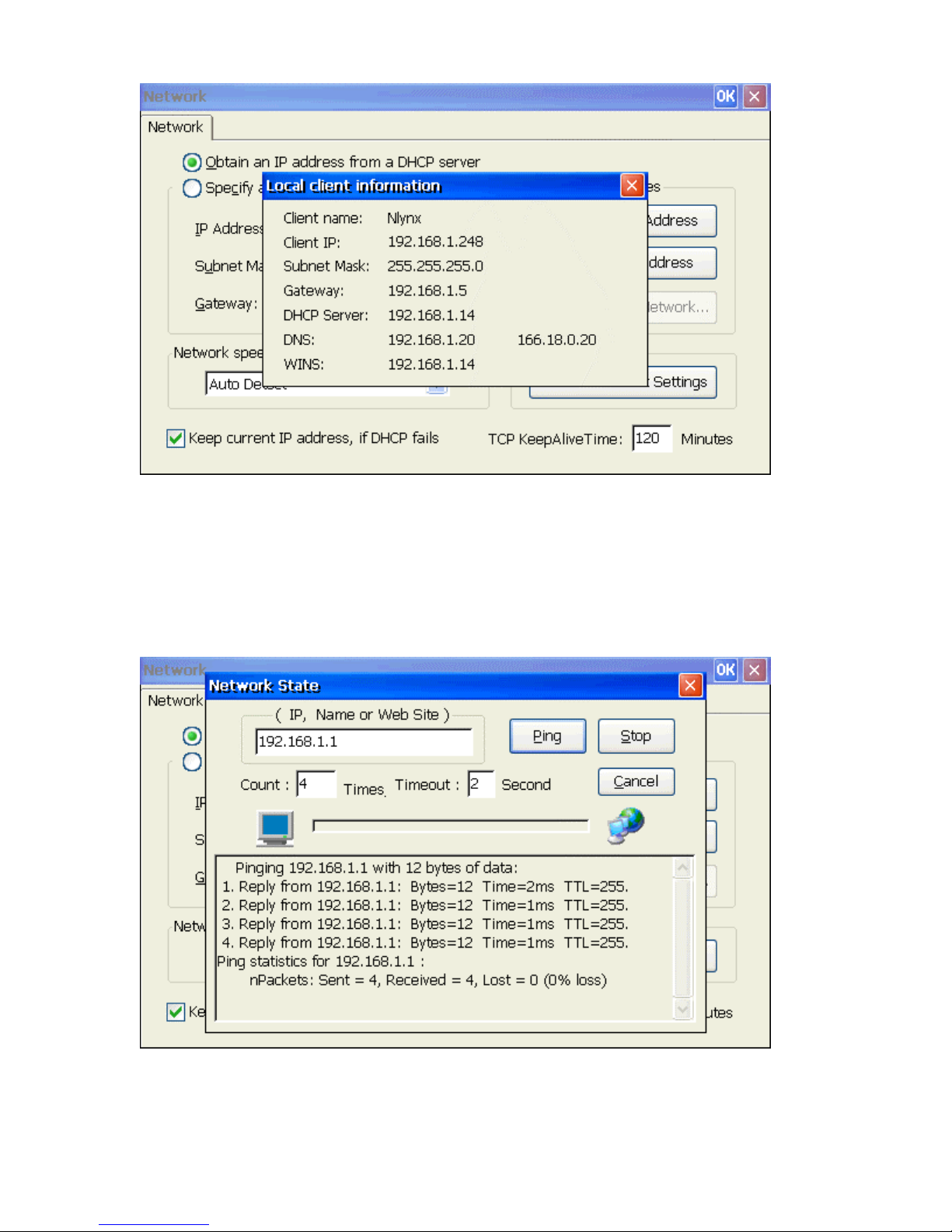
Ping IP Address
Click on the Ping IP Address to display the Network State dialog box. You can ping the
name or IP of a host connected on the network. You even can ping an web site through
the gateway.
You can setup how many times you want to ping for a ping task. Default is 6 times. You
can also setup the timeout value of host response for different network configurations.
The default is 2 seconds.
Advanced Network…
The Advanced Network… button becomes active if you have selected the Specify IP
Address setting. Click on this button to manually set the DNS and WINS IP
information.
Page 61
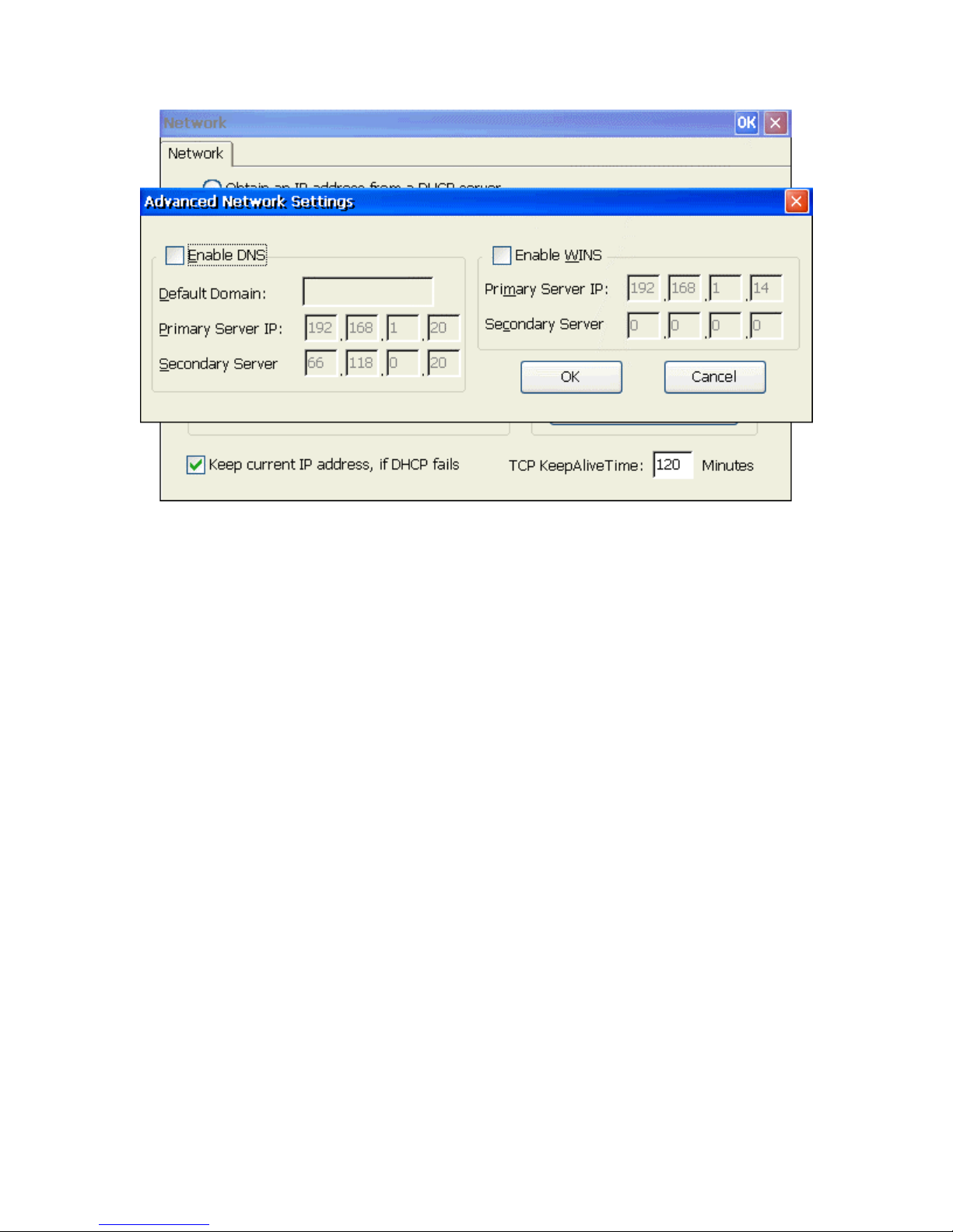
Advanced Network Settings
Enable DNS
Click on the check box to enable the following three fields for the DNS setting.
Default Domain
Enter the default domain name in this field.
Primary Server IP Address
Enter the primary DNS server IP address in this field.
Secondary Server IP Address
Enter the secondary DNS server IP address in this field.
Enable WINS
Click on the check box to enable the following two fields for the WINS setting.
Primary Server IP Address
Enter the primary WINS server IP address in this field.
Secondary Server IP Address
Enter the secondary WINS server IP address in this field
OK
Click on OK button to save the changes and restart the terminal.
Cancel
Click on Cancel button to quit the dialog box without saving changes.
Page 62
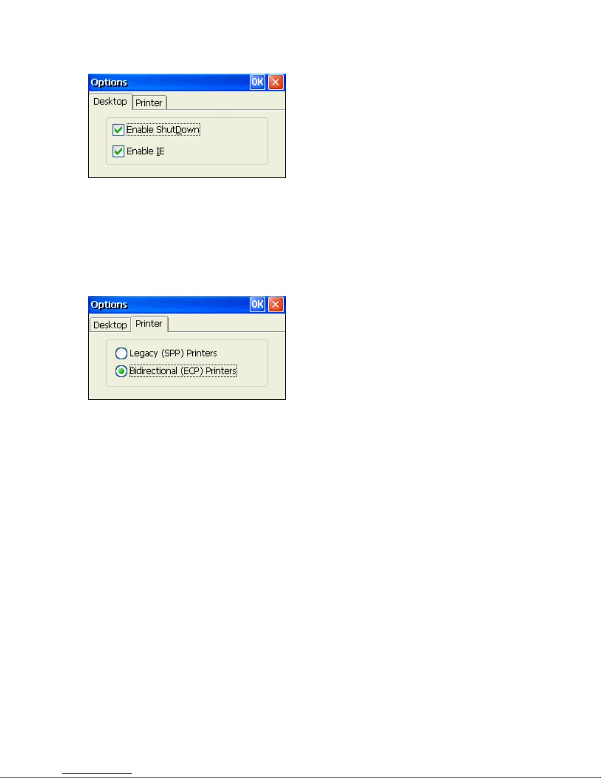
Options
Enable ShutDown
Selecting this option allows a user to power down the unit from the software. The
"ShutDown" option then appears in the "Start" menu. Disabling this requires one to use
the power button to power down the unit. This is set by default.
Enable IE
Selecting this option enables "Internet Explorer" to be available for the user. This is set
by default.
Legacy (SPP) Printers
Selecting this option allows for the use of "older", "slower", Standard Parallel Ports type
printers. SPP ports can be called unidirectional, standard, compatible and other names.
These ports run at very slow speeds.
Bidirectional (ECP) Printers
Selecting this option allows for Enhanced Capabilities Port printers. ECP ports use a
DMA channel, but generally provide only a slight increase in speed. Some printer drivers
can cause communication problems. This is set by default.
Page 63
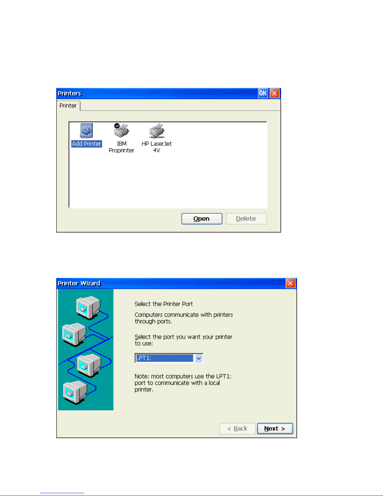
Printers
From the control panel properties sheet, double click the Printers icon to reach the "Add printer"
dialog box.
Add Printer Dialog box
Add Printer
Double click on the "Add Printer" icon to reach the WBT Printer Wizard. This setup
wizard provides five major steps to setup the printer.
Step1: Select the Printer Port
There are five different printing ports, COM1, COM2, LPT1, LPT2(USB) and network, to
select from. If you do not have a USB printer attached, it will not appear in the list.
Page 64
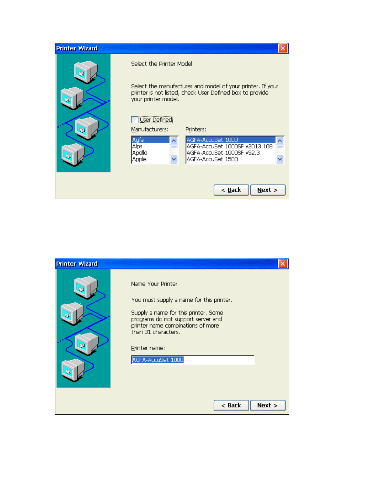
Step2: Select the Printer Model
1. Use the first pull-down list to select the Manufacturers name.
2. Use the second pull-down list to select the Printer Model.
3. If your printer is not on the list, select the User Defined check box.
Step3: Name Printer or select User Defined Manufacturer and Model
If your printer is on the list:
Select a name for your printer and skip to step 4.
Page 65
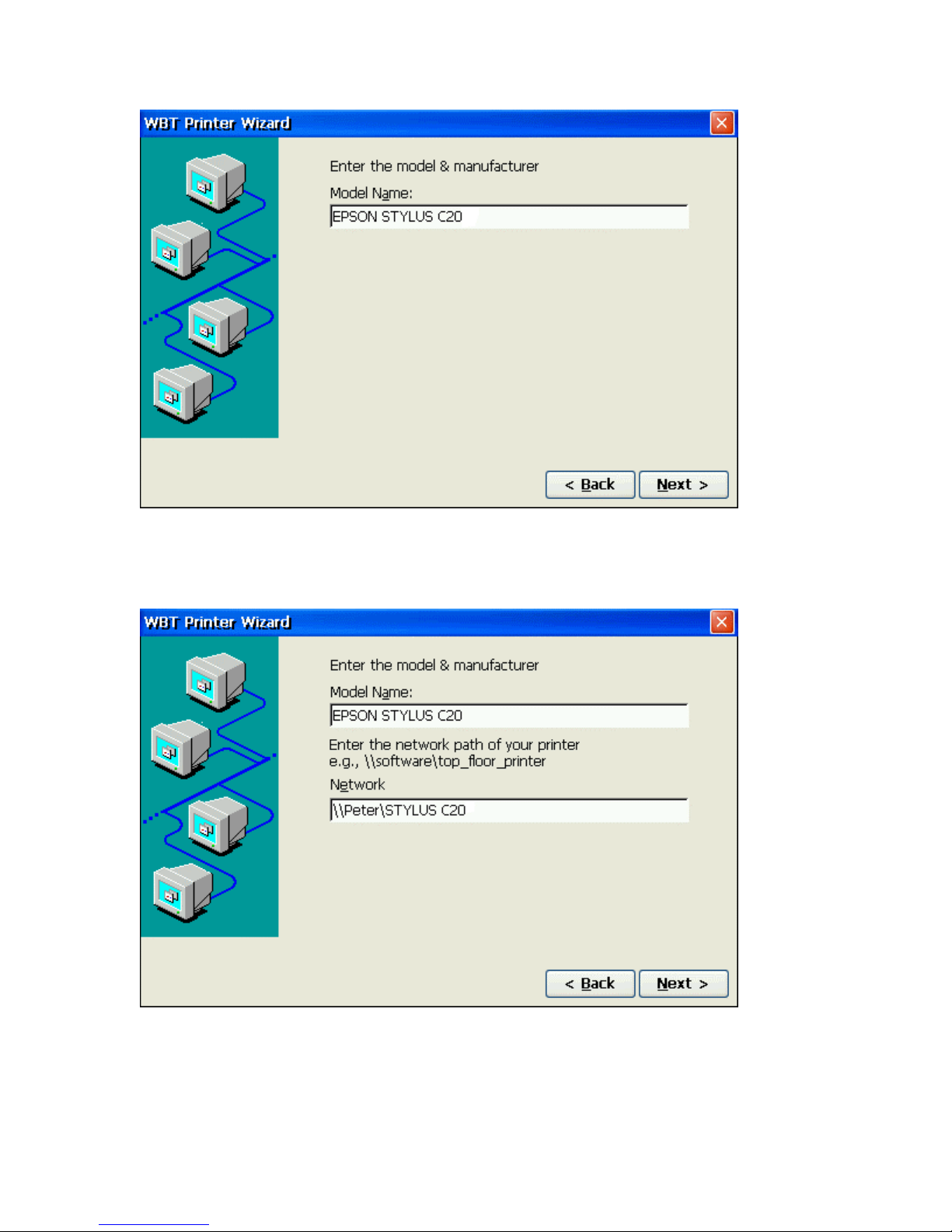
User Defined Printer:
Type in the Manufacturers Name and Model number.
Type in network path and printer name.
Page 66
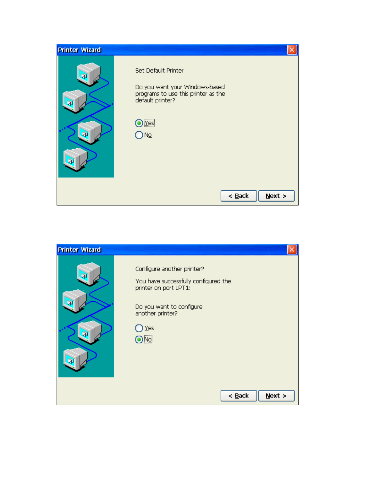
Step4: Set Default Printer
Select the appropriate radio button whether or not you want this to be your default printer.
Step5: Configure another printer
If you are done adding new printers, select No. If not, select Yes and return to Step 1.
Page 67
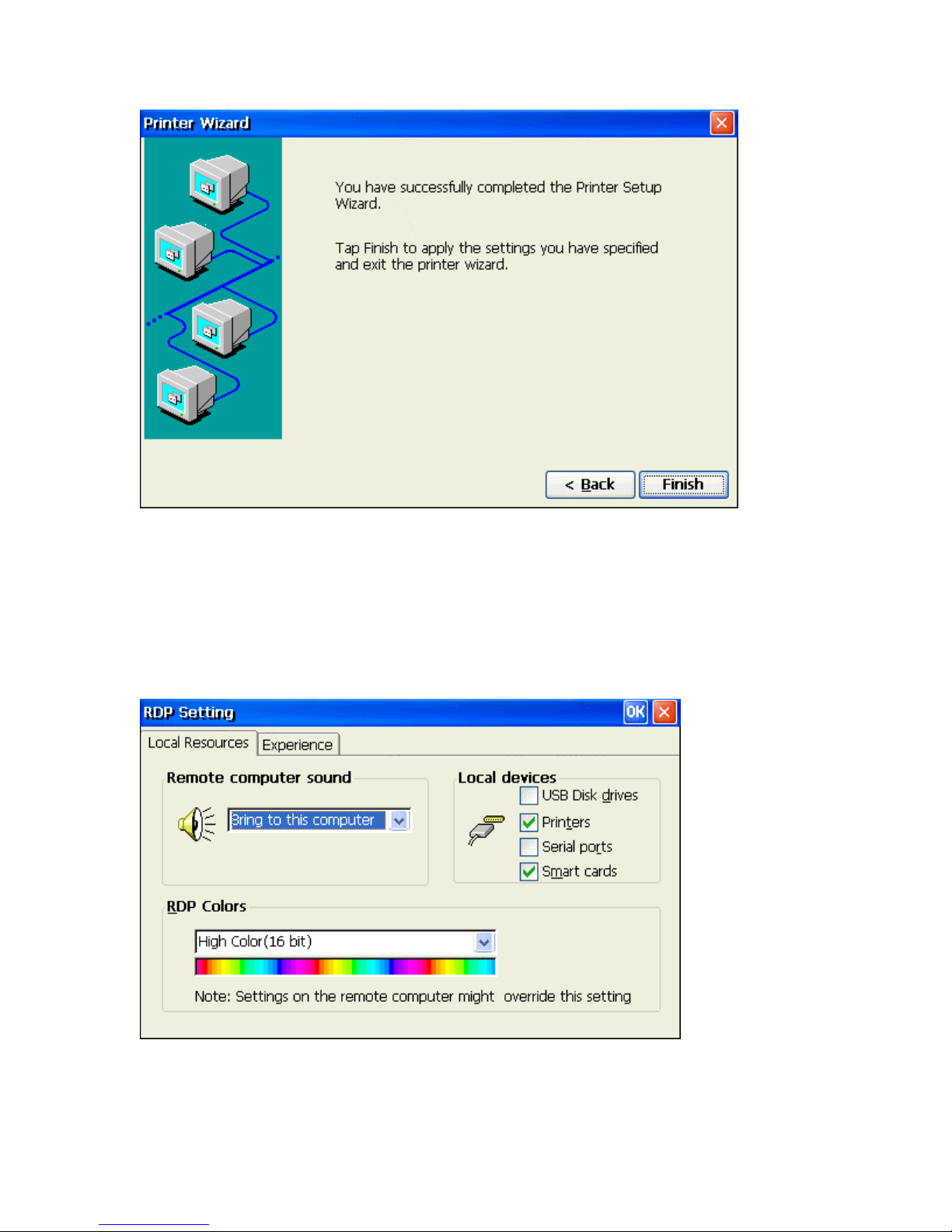
Step6: Completed the Printer Setup
Click on Finish to complete the process.
RDP Setting
Use the RDP Local Resources Properties Sheet to configure your terminal's local audio and
devices.
Local Resources Tab
Page 68

Remote computer sound
Select one of the following options from the pull-down list.
Bring to this computer -- Mapping the audio (sound) from the server to the terminal.
Do not play -- Mapping the audio (sound) from the server to the terminal.
Leave at remote computer -- Leave the audio at remote server, does not map the
audio (sound) from the server to the terminal.
Local devices
USB Disk drives -- Enable local USB port mapping for USB Disk drivers such as
USB FDD, HDD, Flash Disk and CDROM.
Printers -- Enable local parallel port mapping. It supports both parallel printers from
LPT1 and USB printers from USB port.
Serials ports -- Enable local serial ports mapping.
Smart cards -- Enable local smart card mapping.
RDP Colors – From the pull-down list, select the color resolution for the RDP session.
Experience Tab
Use the RDP Experience options to choose your connection speed to optimize performance.
From the pull-down list, select your connection speed to automatically adjust the properties
listed for optimum performance. If the connection speed is left to the default setting of
"Custom", you can manually set the options yourself.
Page 69
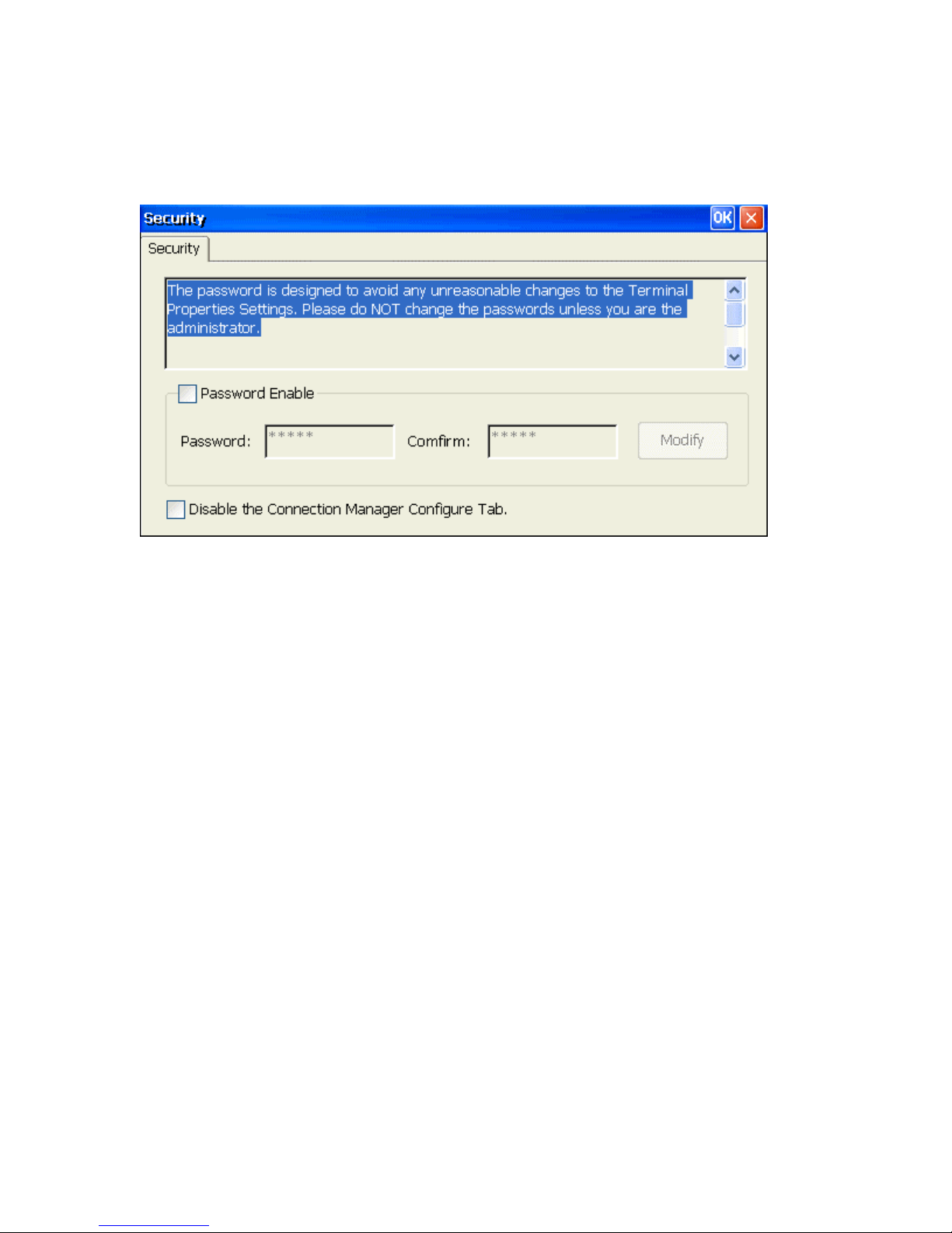
Security
Using the security dialog box, you can prevent someone from changing your terminal's
properties.
Settings Window
Enable Password
Enable this check box to activate the terminal's security. If enabled, you can set and
confirm a new password. The factory default password is "guest".
Note: The password is designed to avoid any unreasonable change to the
Terminal Properties Settings. Please do NOT change the password unless you are
the administrator. If you forget the password, you will need outside assistance to
get back in to configure the terminal. Please save your password carefully.
There are two methods to recover from forgetting the password.
• Contact your vendor for help. (to get a super password.)
• Use the Remote Management software to recall your terminal settings.
Disable Terminal Connection Configure Tab
Select this check box to disable the configure tab of terminal connection manager.
Page 70
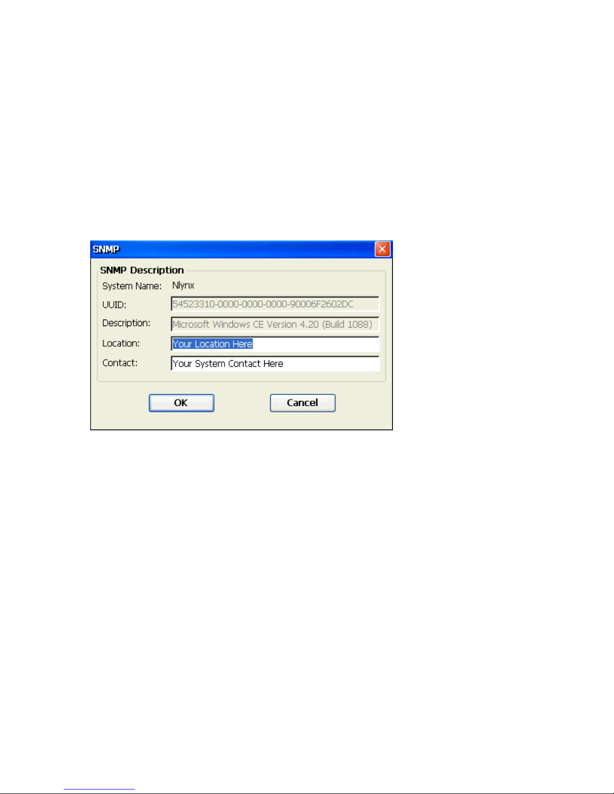
SNMP
Simple Network Management Protocol (SNMP) is the Internet Standard protocol for network
management and part of the TCP/IP protocol suite. SNMP was developed by the Internet
community to monitor and manage networks. It uses a distributed architecture that consists of
managers and agents.
The SNMP agent is an SNMP application that monitors network traffic and responds to queries
from SNMP manager applications. The agent also notifies the manager when significant events
occur by sending a trap.
An SNMP manager is an SNMP application that generates queries to SNMP-agent applications
and receives traps from SNMP-agent applications.
Settings Window
1. Type in the location of this device to so a network manager can easily find the
terminal in case of any problems.
2. Type in the System Contact in case someone needs to be made aware of any
problems.
Page 71
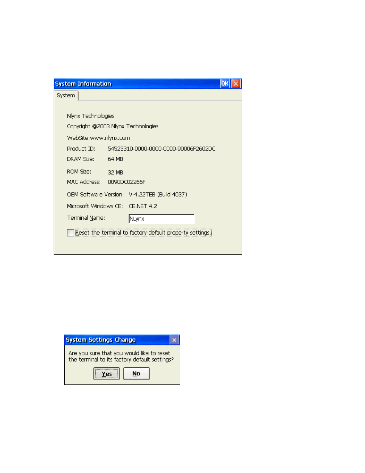
System
The System Information window provides general terminal hardware configuration data such as
product ID, memory configuration, Ethernet Mac address and software version numbers.
Information Window
Terminal Name
Type in a unique Terminal Name so the device individually recognized by your server.
Giving the WBT a unique name will insure access to network drives. For terminal
emulation and/or web browsing requirements only, changing the device name is not
necessary. The length of the terminal name is limited to a maximum of 15 characters.
Reset the terminal to factory-default property settings
Click on this check box to reset the terminal to its factory default setting. Because this
process requires the unit to be re-booted, a confirmation box will appear.
Click Yes to confirm the operation or No to cancel out.
OK
Click on OK button to save changes and quit the dialog box. Click on X button to quit
the dialog box without saving changes.
Page 72
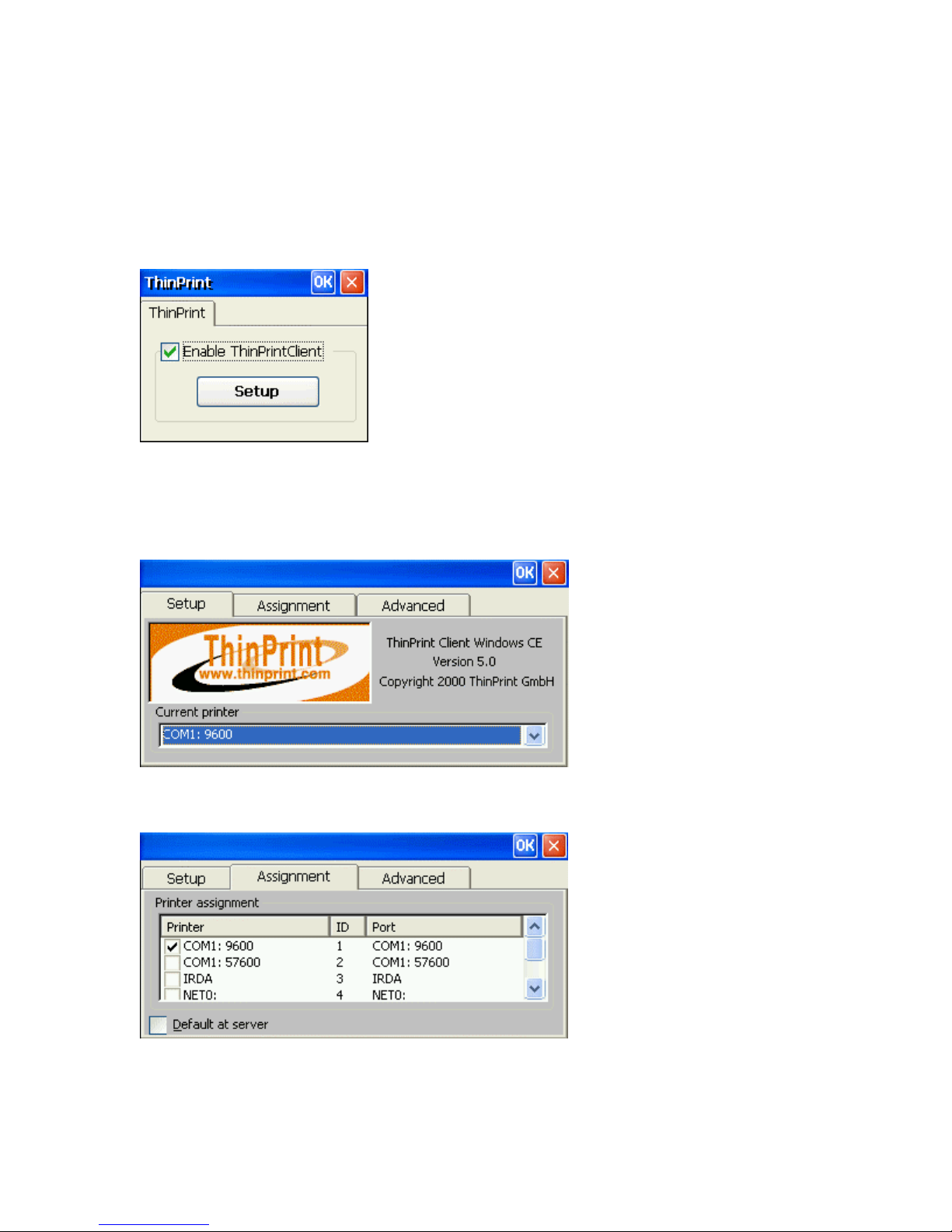
ThinPrint
The ThinPrint enables direct printing program from the terminal to network printers. Together
with Citrix MetaFrame application server software, this new feature gives a powerful solution for
remote offices and wireless LANs. With this new ThinPrint Client, a print job can be delivered
over the Citrix ICA protocol to the device and from there direct to the network printer; there is
no longer a need for a print server in addition to a network printer.
Enable Window
1. If it is blank, click on the Enable ThinPrintClient check box to enable the
ThinPrinterClient.
2. Click the setup button to open the ThinPrint properties window.
Setup Tab
Assignment Tab
Page 73
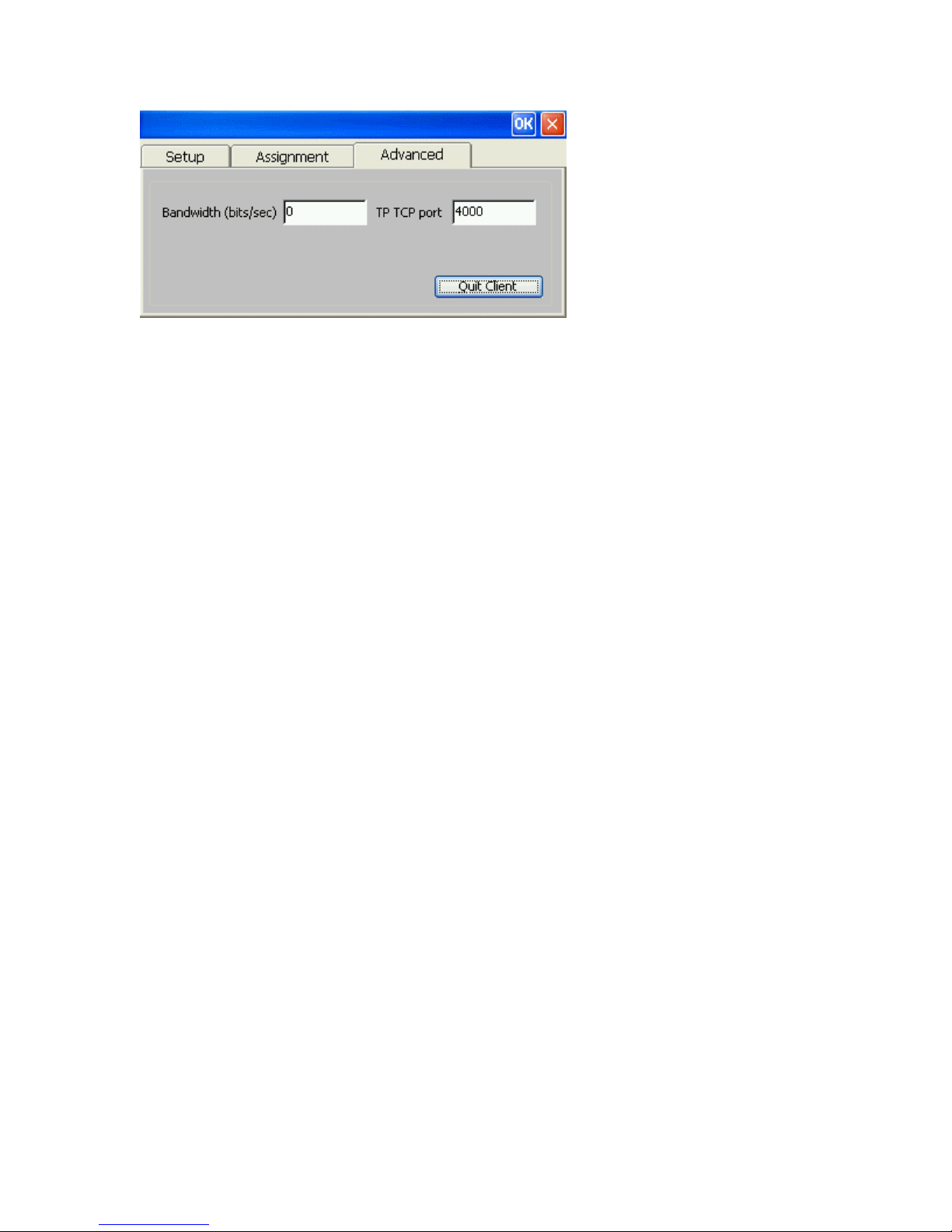
Advanced Tab
Page 74
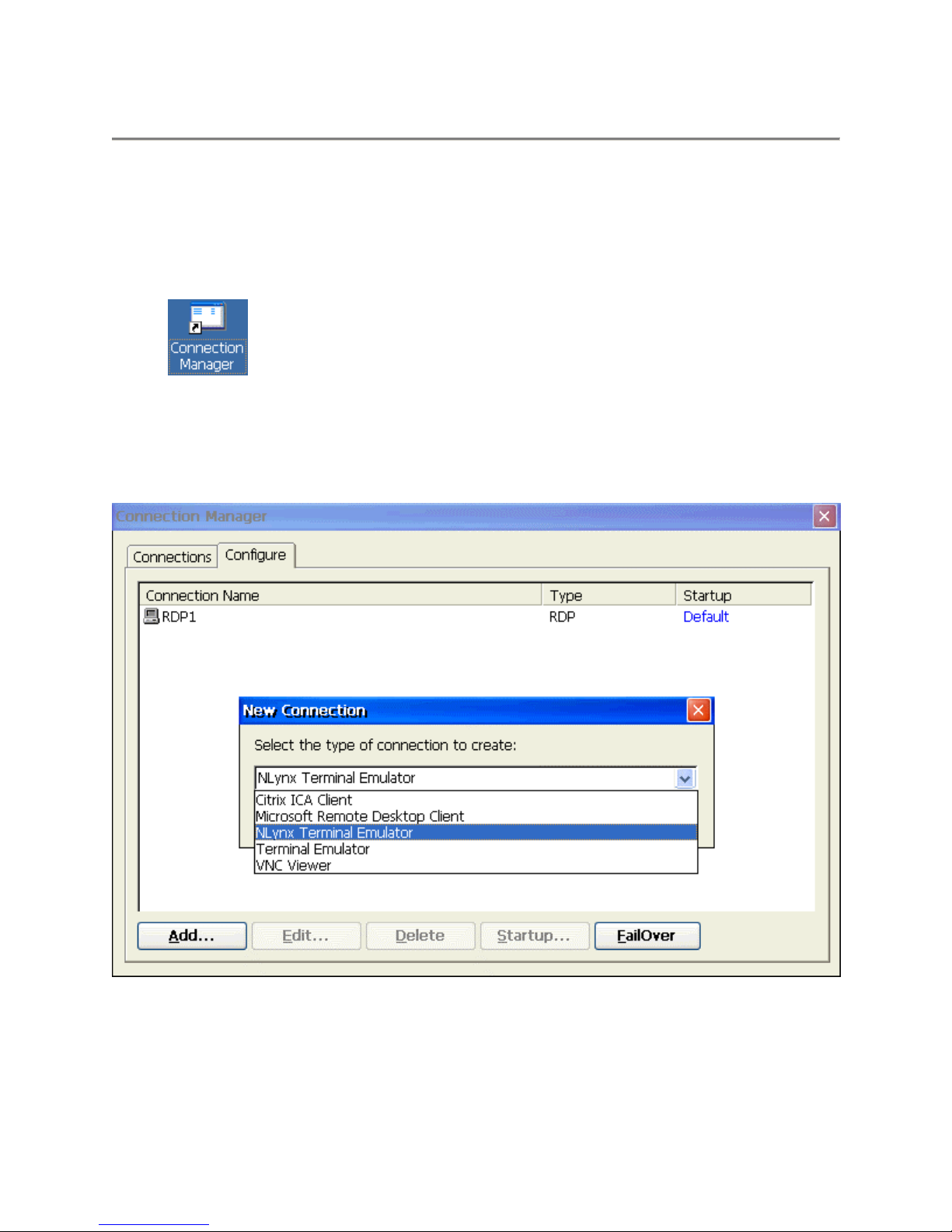
NLynx TN5250 Terminal Emulation
5250 Terminal Session Setup
From the terminal desktop, click on the “Connection Manager” icon (shown below) to bring up
the “Terminal Connection Manager” setup window. This is the same as selecting Start >
Programs > Connection Manager from the Taskbar Menu.
Connection Manager Desktop Icon
1. Once the Connection Manager window is open, select the Configure tab.
2. Click on the Add button to bring up the New Connection dialog box.
Connection Manager Window
1. Select the NLynx Terminal Emulator option from the pull down list and click on the OK
button.
Page 75
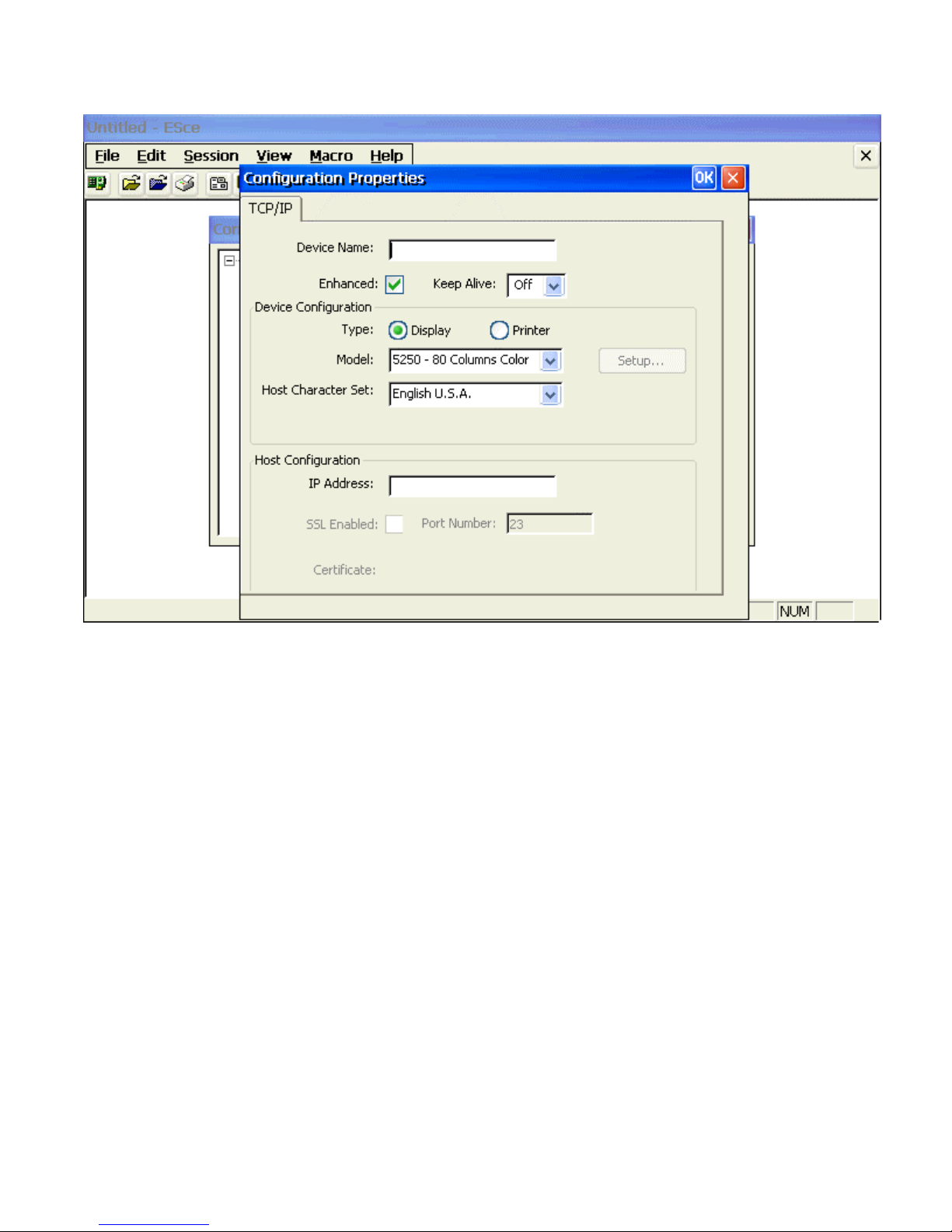
Configure Dialog Box
1. Type in a Device Name. The device name is used to identify which devices you are
using when running the emulator.
Note: It is recommended that you use a device name that has part of your IP Address or
Work Station Address at the end. For TN5250E sessions where the name provided is
shown on the AS/400, the initials or name of the user is helpful. It is also useful to
reference the application that the session is usually used for.
You can use any number and letter combinations along with the characters @ $ and _ up
to a maximum number of 10 for TN5250E sessions.
• The characters ? < > , . / \ | * and * are not accepted by the input field
• The characters - (dash) and (space) are accepted by the field but are not
allowed by the AS/400.
• The characters ~ ! % ^ & ( ) - + = { } [ ] are allowed but should be
avoided because the character will be changed to a # at the AS/400.
2. For the Device Configuration Type, select Display.
3. Select either the 80 or 132 column display options from the Model pull down list.
4. Select the appropriate option from the Host Character Set pull down list.
5. Type in the IP Address of the 5250 Host computer. If you have a DNS server on the
network, you may type in a host name instead of an IP address.
6. Click the OK button to complete the setup. The session should now appear in the
Connection Manager window.
Page 76
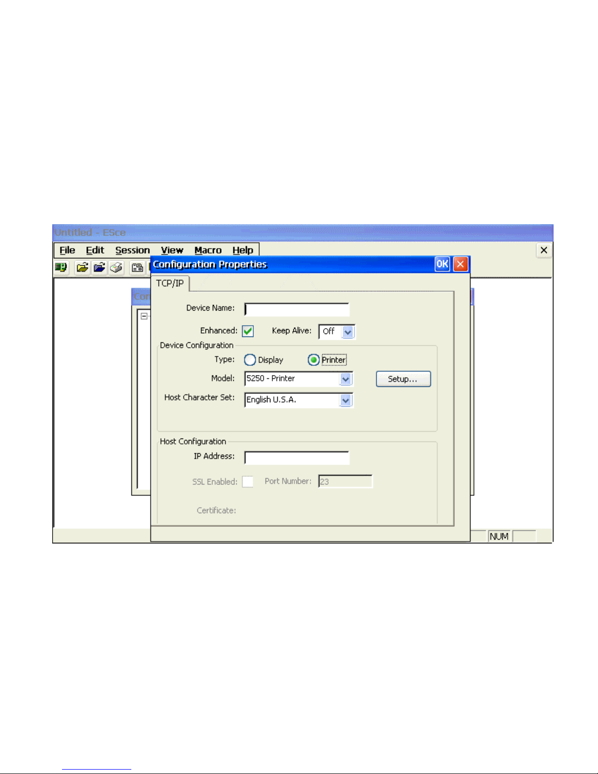
5250 Printer Session Setup
1. From the terminal desktop, click on the “Connection Manager” icon (shown below) to
bring up the “Terminal Connection Manager” setup window. This is the same as
selecting Start > Programs > Connection Manager from the Taskbar Menu.
2. Once the Connection Manager window is open, select the Configure tab.
3. Click on the Add button to bring up the New Connection dialog box.
4. Select the NLynx Terminal Emulator option from the pull down list and click on the OK
button.
5. Type in a Device Name. The device name is used to identify which devices you are
using when running the emulator
6. For the Device Configuration Type, select Printer.
7. Select the Setup button to bring up the Printer Setup window.
Page 77
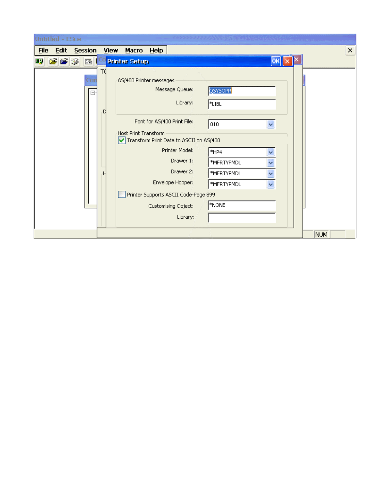
8. Leave the default as is or enter in another name of the AS/400 Message Queue where you
want printer messages to be sent.
9. Leave the default as is or enter in another Library name that contains the list of printer
messages.
10. Leave the default as is or select another AS/400 printer font file from the drop down list.
11. Place a check in the Transform Print Data to ASCII on AS/400 check box to select Host
Print Transform.
Note: See your MIS Administrator for device settings entered here. By selecting
Host Print Transform, the “Printer Selection Menu” will change and several new
options appear. The printer you are using and OS of the AS/400 determine the
settings here. The most important setting here is Printer Model.
12. Select the Printer Model from the drop down list or type it in the window directly.
13. Select the paper source from the drop down lists for each of the Drawer1, Drawer2 and
Envelope Hopper options. If you leave the default setting *MFRTYPMDL as is, the
system uses the suggested setting for this printer type.
14. If the Printer Supports ASCII Code-Page 899, place a check in the check box.
15. Click OK to complete this screen.
16. Type in the IP Address of the 5250 Host computer. If you have a DNS server on the
network, you may type in a host name instead of an IP address.
17. Click the OK button to complete the setup. The session should now appear in the
Connection Manager window.
Page 78
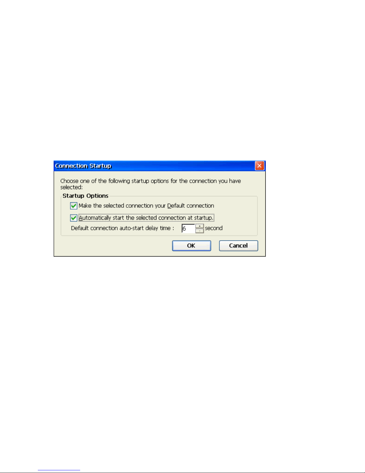
Starting a Session
There are three ways to start a NLynx emulation session.
Method 1. Autostart a Session on Power Up
Using the “Connection Startup Dialog Box”, you can pre-set sessions to automatically
connect to their servers when terminal is turned on.
1. From the terminal desktop, click on the “Connection Manager” icon (shown below) to
bring up the “Terminal Connection Manager” setup window. This is the same as
selecting Start > Programs > Connection Manager from the Taskbar Menu.
2. Once the Connection Manager window is open, select the Configure tab.
3. Select a session that you want to Startup when the MinIT6000 is turned on and click on
the "Startup" button.
Connection Startup Dialog Box
4. Place a check mark by the Make the selected connection your default connection option if
you want this session to be your default connection.
5. Place a check mark by the Automatically start the selected connection at startup option to
enable the Autostart function.
6. Adjust the auto-start delay time by changing the "seconds" value. This might be
important in some networks because it allows the unit enough time to obtain DHCP
information from the DHCP server (if set for) before it tries to connect to the host.
7. Click the OK button to complete the setup.
8. Repeat steps 3 - 7 for any additional sessions that you would like to auto-start.
9. Click on the X to close the Connection Manager
Method 2. From the Connection Manager
1. From the terminal desktop, click on the “Connection Manager” icon (shown below) to
bring up the “Terminal Connection Manager” setup window. This is the same as
selecting Start > Programs > Connection Manager from the Taskbar Menu.
2. Once the Connection Manager window is open, select the Connections tab.
Page 79
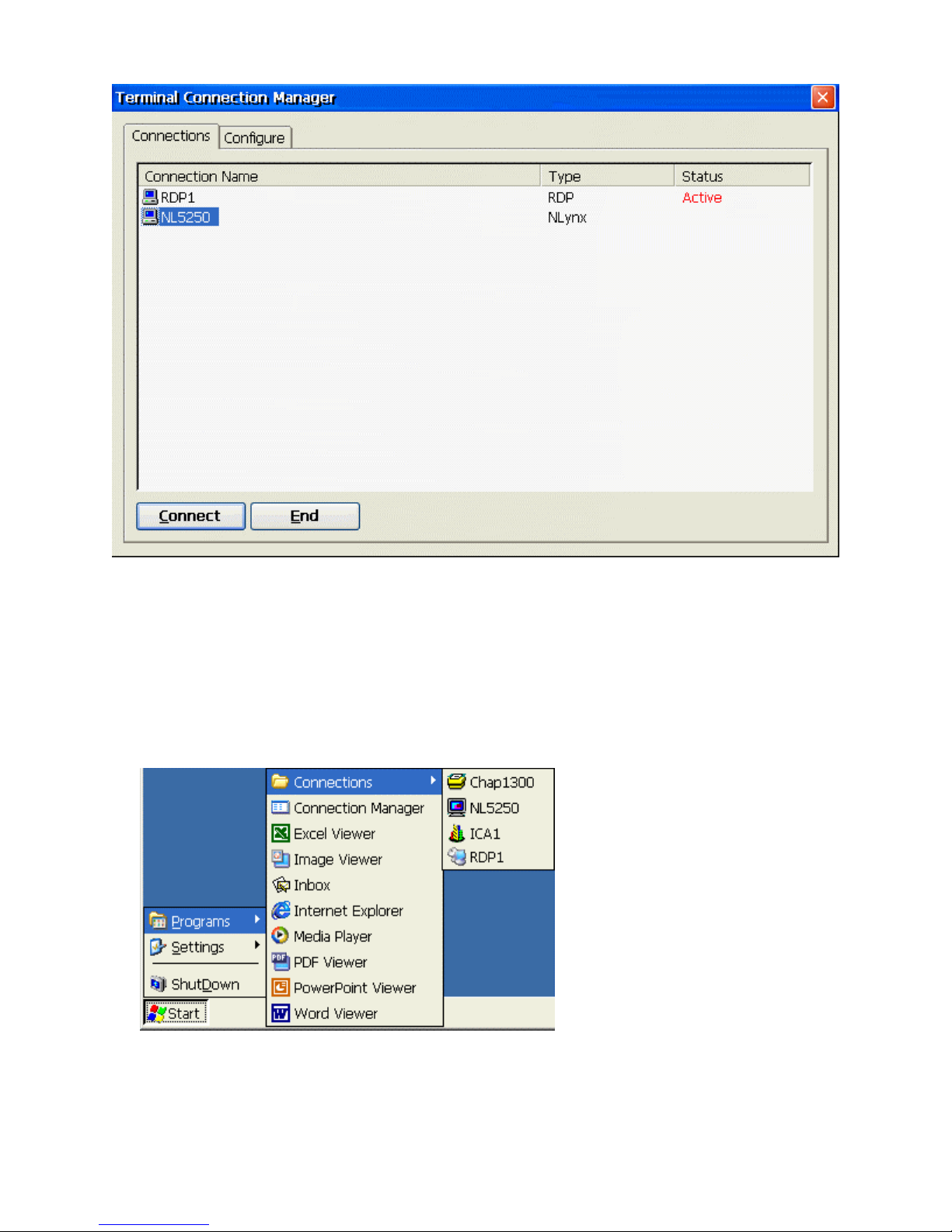
3. Select the Connection that you wish to start.
4. Click on the Connect button to start the session.
5. Click on the X button to close the Connection Manager window.
Method 3. From the Start menu
1. From the terminal desktop, Select Start > Programs > Connections > session name from
the Taskbar Menu.
Page 80
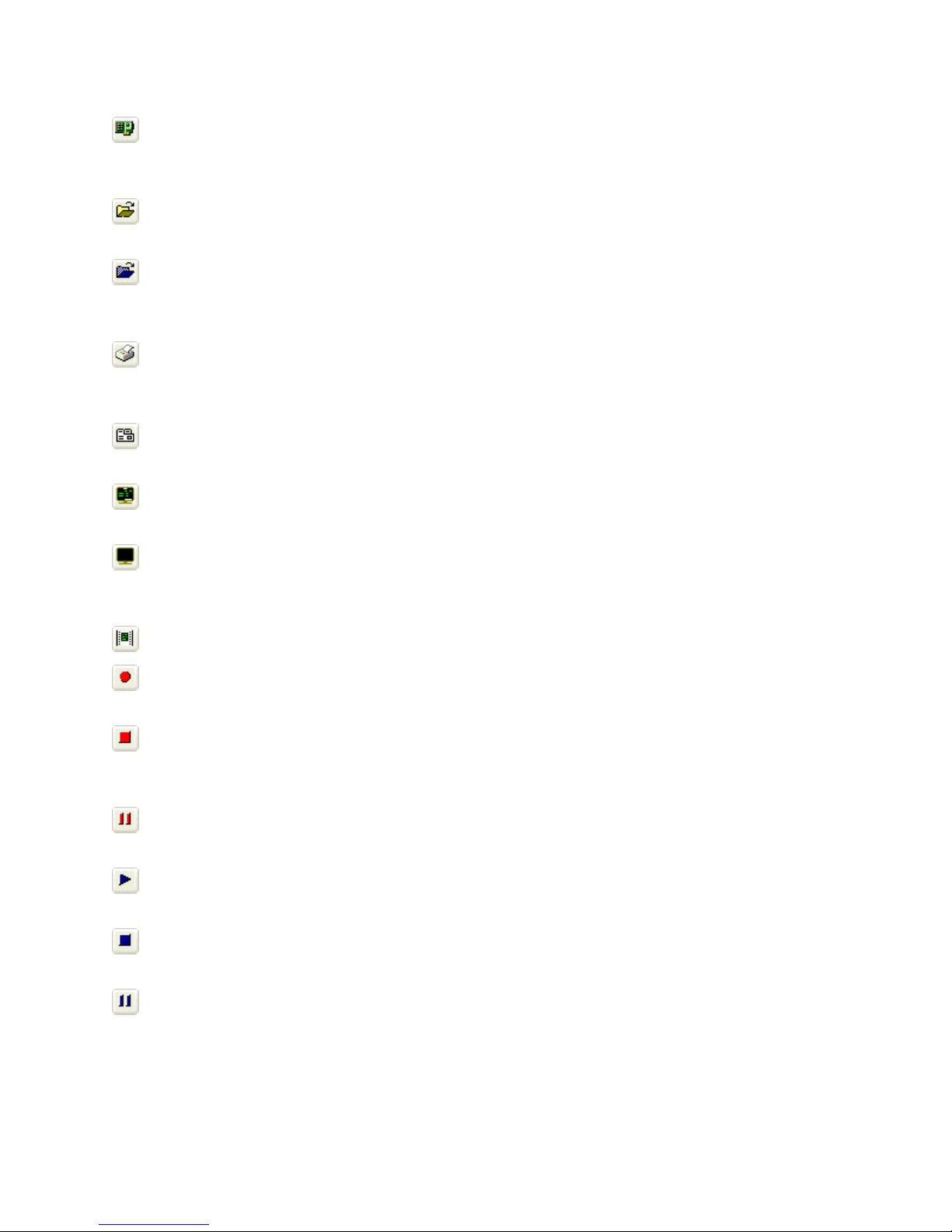
Using the Toolbar Buttons
Configure normally would bring up the Configure Devices window however, it is not
active in this version of the emulator because devices can be configured through the
Connection Manager. This is the same as selecting File > Configure.
Open brings up the Open window at the root directory. Used to open or find a display or
printer session file. This is the same as selecting File > Open.
Open Display brings up the Open window at the DiskOnChip directory showing the
available display session files. This allows you to select a pre-configured session file.
This is the same as selecting File > Open Display.
Open Printer brings up the Open window at the DiskOnChip directory showing the
available printer session files. This allows you to select a pre-configured session file.
This is the same as selecting File > Open Printer.
Properties brings up the ESce Display dialog window. This allows you to edit/change
the session properties. This is the same as selecting Session > Properties.
Connect starts the connection between the PC and the host computer. This is the same as
selecting Session > Connect.
Disconnect breaks the connection between the PC and the host computer. Always sign
off the host computer before disconnecting. This is the same as selecting Session>
Disconnect.
Print prints the active host screen. This is the same as selecting File > Print.
Record Macro turns on the macro recorder. All keystrokes are recorded in the macro
file until you press Stop. This is the same as selecting Macro > Record > Record.
Stop Recording turns off the macro recording. You will be prompted to enter a name for
the macro file which will be saved to the folder containing the emulator program files.
This is the same as selecting Macro > Record > Stop.
Pause Recording pauses an in-progress macro. To begin recording again, choose
Record. This is the same as selecting Macro > Record > Pause.
Play Macro plays a macro that has been recorded and saved. You will be prompted to
choose a macro file to play. This is the same as selecting Macro > Play > Play.
Stop Macro stops a macro during playback. This is the same as selecting Macro > Play
> Stop.
Pause Macro pauses the macro during playback. To restart the macro, select play. This
is the same as selecting Macro > Play > Pause.
Page 81

Other Menu Functions
• File > Save As allows you to enter a different name for an existing session file.
• File > Exit All ends all active emulator connections at the same time. To close one
emulator connection at a time, use the Exit command.
• File > Exit ends the currently selected active emulator connection. To close all active
emulator connections at one time, use the Exit All command.
• Edit > Copy copies the selected area of the host screen to the Clipboard.
• Edit > Paste pastes the contents of the Clipboard to the specified location.
• Edit > Select All selects the entire screen so you can copy it to the clipboard.
• Edit > Clear Selection clears the selection box from the host screen.
• View > Main Toolbar, select to toggle the command key toolbar on and off.
• View > Function Keys, select to toggle the function key toolbar on and off.
• View > Full Screen, select to toggle full screen mode on and off.
Note: To close or exit an active session window when you are in Full Screen mode,
select the <ALT> key to bring up the File menu window. This will allow you to select
either the Exit All or Exit menu functions.
• View > Ruler, select to toggle displaying the ruler.
• View > Status Bar, select to toggle the status bar on and off.
• View > Test Screen Displays the color attributes. Type an attribute number and select
enter to display that attribute in the input field box.
• Help > About displays the version information.
Page 82
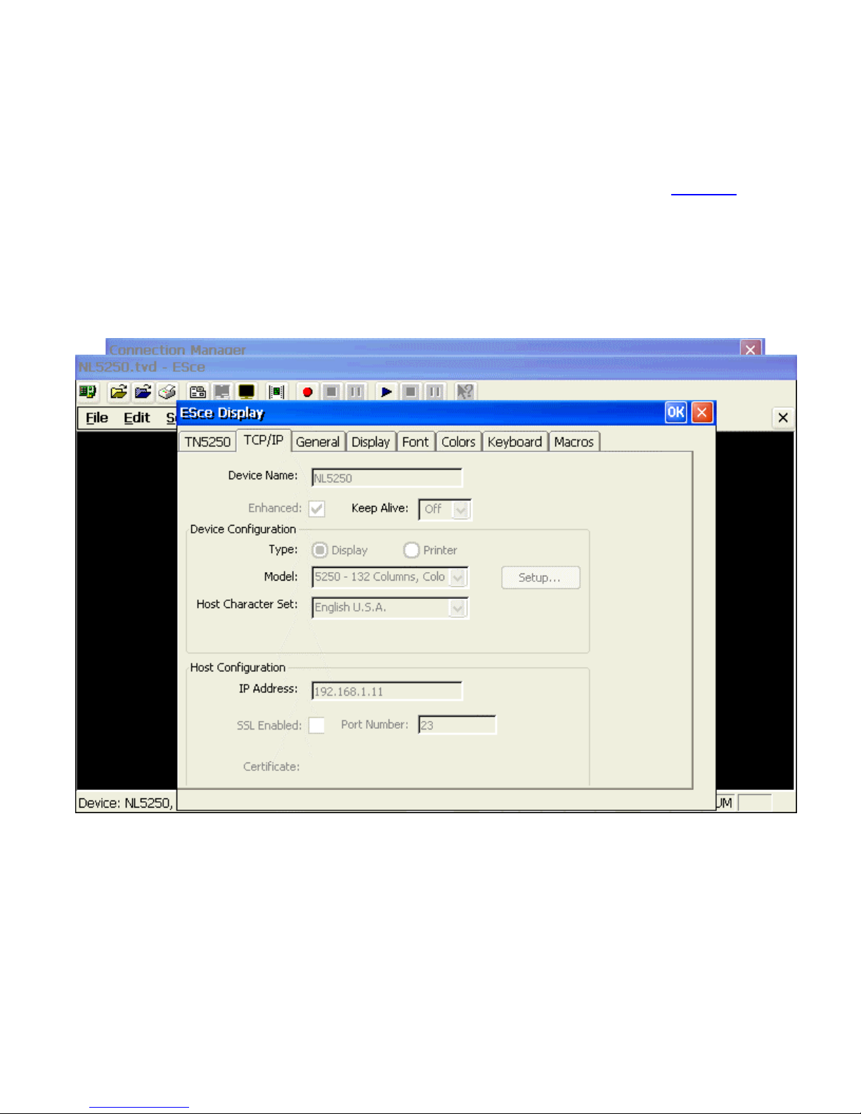
Editing Session Properties
There are two ways to edit an NLynx emulation session.
Method 1. From the Connection Manager
This method allows you to edit all basic session properties except the main TCP/IP settings.
To change the "Device Name" or "Host IP Address" information, please refer to Method 2.
1. From the terminal desktop, click on the “Connection Manager” icon (shown below) to
bring up the “Terminal Connection Manager” setup window. This is the same as
selecting Start > Programs > Connection Manager from the Taskbar Menu.
2. Once the Connection Manager window is open, select the Configure tab.
3. Click on the Edit button to bring up the ESce Display window.
4. Select the appropriate tab to modify the specific entries.
Page 83
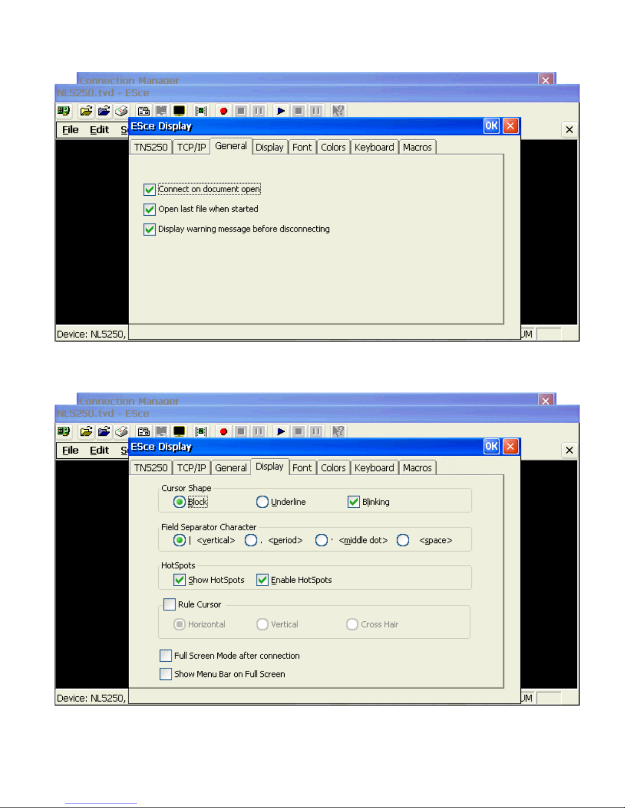
General Tab
These options are session independent. Place a check mark in the appropriate check boxes to
enable the indicated operations.
Display Tab
Change the value for Cursor Shape, Field Separator Character, Hot Spots, Rule Cursor
and Full Screen Mode by selecting the appropriate options and/or enabling the appropriate
action.
Page 84
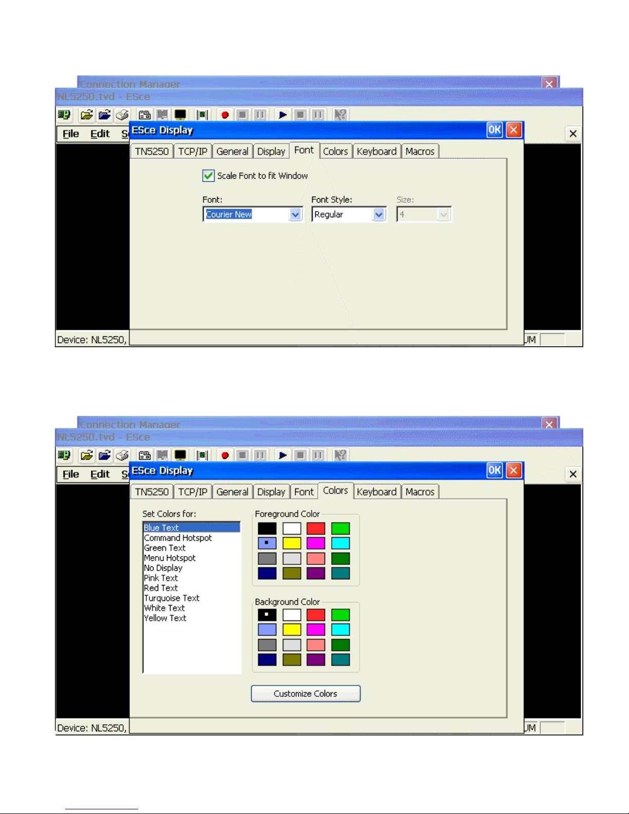
Font Tab
Select the appropriate Font and Font Style from the available pull down lists. Place a check
mark in the check box to Scale Font to fit Window.
Colors Tab
Page 85
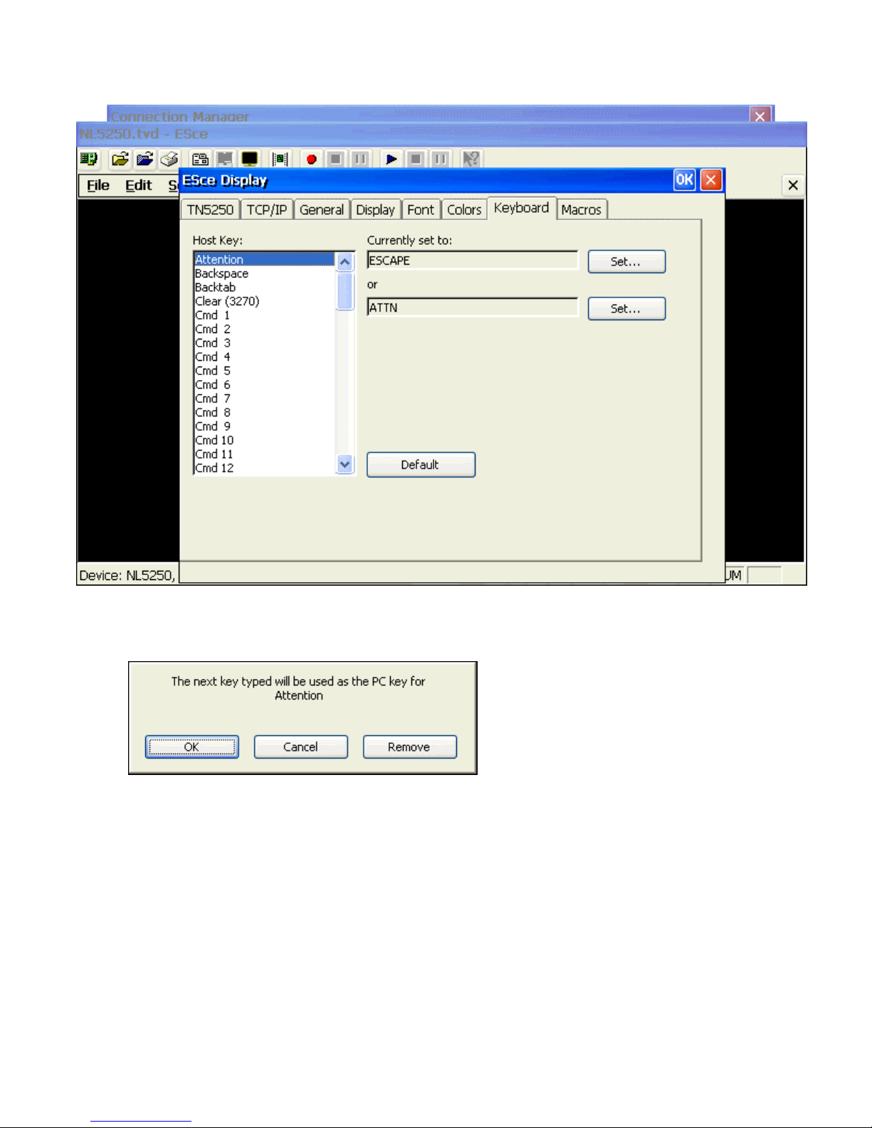
Keyboard Tab
1. Modify the keyboard mapping by selecting a Host Key to be remapped.
2. Select the Set… button. This will bring up the following dialog box
3. The next key you type will become the key you want to use for that Host Key function.
4. After the conformation text has appeared, select the OK button to complete the process.
TN5250 Tab
The Connection Name is always TCP/IP and the tab name is the same even if you have
selected a 3270 session. There is no reason to make any changes here.
Page 86
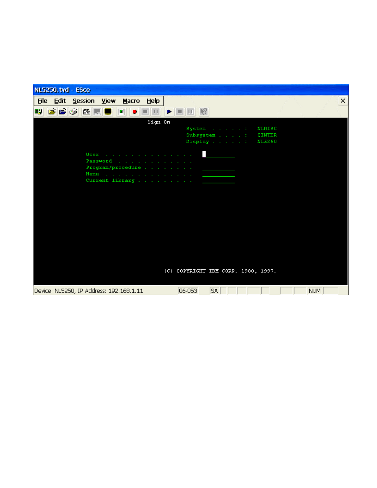
Method 2. From the Session Window
1. Start the appropriate NLynx emulation session that you wish to edit from the
Connection Manager or by selecting Start > Programs > Connections > session
name from the Taskbar Menu.
1. Click on the Disconnect icon on the toolbar to break the connection between the
MinIT6000 and the host computer.
Note: This is very important because it will allow you to modify the TCP/IP
information such as the Device Name and Host IP Address.
2. Click on the Properties icon on the toolbar to bring up the ESce Display window.
3. Select the appropriate tab to modify the specific entries.
Page 87

Text Terminal Emulator
Please see the PT User’s Guide.pdf
Citrix ICA Client
Please see the ICA User’s Guide.pdf
Page 88
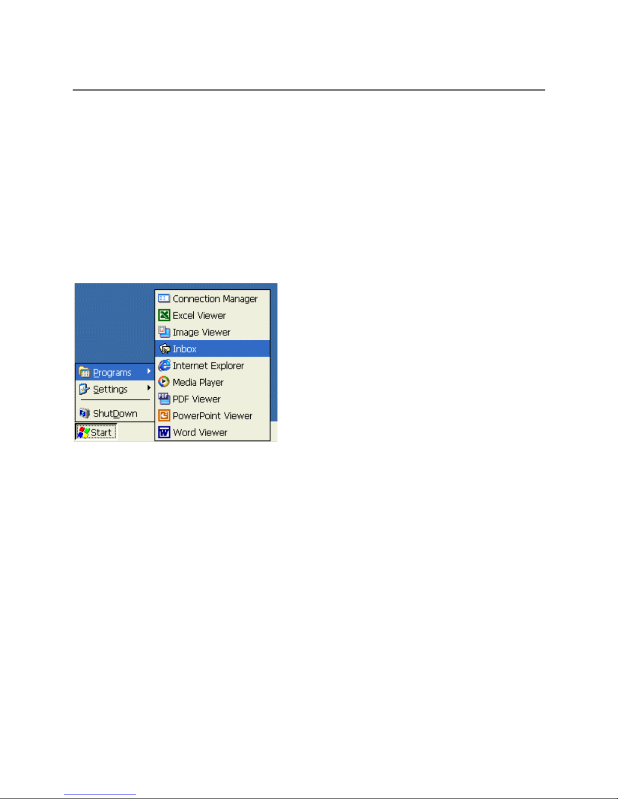
Email User's Guide
About
You can send and receive e-mail by connecting to a POP3 or IMAP4 server. Inbox contains an email service for each method you use. For example, if you receive e-mail through a connection to
a POP3 server and through a connection to an IMAP4 server, Inbox will contain two services:
POP3 Mail and IMAP4 Mail. Each e-mail service has its own folder hierarchy with four default
folders: Inbox, Outbox, Deleted (local), and Sent. The messages you receive and send through
the mail service are stored in these folders
Starting Email
Similar to a PC, the Email Client is opened through the Start Menu bar.
Bringing up Email
To bring up Email, select Start > Programs > Inbox from the “Start” menu on the desktop.
Page 89
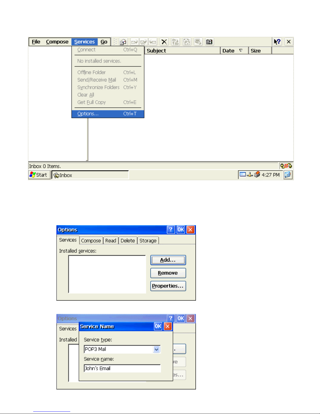
Email Client Window
Setup Mail Service
To connect to your POP3 or IMAP4 mail server, you need to set up an Inbox mail service.
1. Begin by clicking on the Options selection under the Services pull-down menu.
This will bring up the Options dialog box.
2. Click on the Add button to create a new service.
Page 90
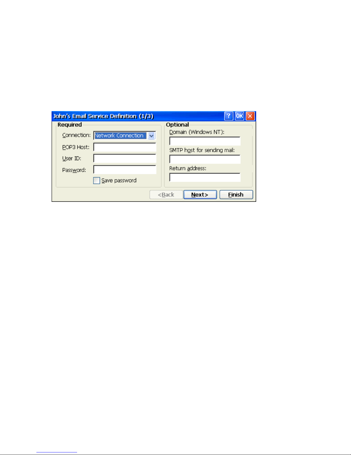
3. From the Service type list, select POP3 Mail or IMAP4 Mail. (POP3 is the most common
mail protocol for ISPs.
4. Enter a unique name for the Service name and select OK.
5. Follow the steps in the Setup wizard to setup the Service Definition, General Preferences,
and Inbox Preferences.
Set Service Definitions - Setup Wizard Screen 1
The Mail Service Setup wizard appears after you add a service. If you are adjusting the
settings of an existing service, select Services > Options, select the service you are using,
and then Properties. In the Service Definition dialog box, complete the following entries as
needed.
Connection
If you are receiving e-mail through a network (Ethernet) connection, select Network
Connection. If you want Inbox to use your current (i.e. dial-up) connection, select
(none). If you receive your e-mail through a dial-up connection and have not created one
yet, select Create new connection, double-tap or double-click the Make New
Connection icon, and follow the instructions in the wizard. When finished, select Inbox in
the Taskbar and continue setting up Inbox.
Pop3 Host
(POP3 only): Enter the name of the mail server you use to receive and send messages.
Server
(IMAP4 only): Enter the name of the mail server you use to receive and send messages.
User ID
Enter the user name or mailbox ID assigned to you.
Password
Enter the password you use to access this mail account. If you do not want to be
prompted to enter the password each time you connect, select Save password.
Domain (Windows NT)
Enter your Windows NT domain name. This name is required only when connecting to
networks, such as a corporate network, that use Windows NT domain security. This is not
required for most ISP accounts. If you have trouble connecting, try clearing this box.
Page 91
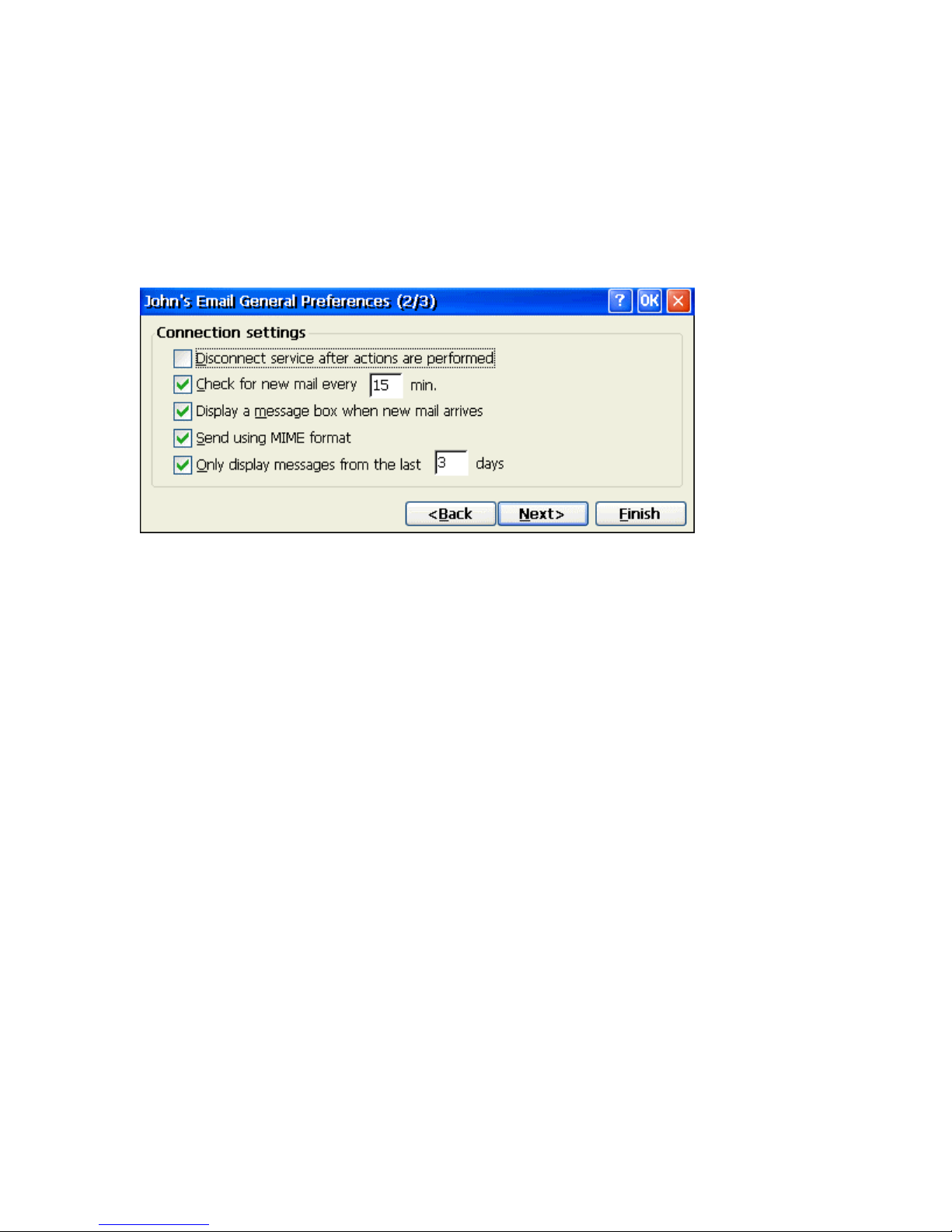
SMTP Host
If your mail service uses a separate server for SMTP, enter the name in the box. If you're
setting up a POP3 Mail service with an ISP, the ISP must use an SMTP mail gateway.
Return Address
By default, the return address is set to username@POP3host or username@Servername,
depending on the service you are using. If this is not your e-mail address, enter the
correct address in the box.
Set Service Preferences - Setup Wizard Screen 2
If you are adjusting the settings of an existing service, select Services > Options, select the
service you are using, select Properties, and then select Next. In the General Preferences
dialog box, choose any of the following settings, all of which are optional.
Disconnect service after actions are performed
Select to automatically disconnect from the server upon completion of all pending
actions. This option minimizes connect time and cost.
Check for new messages every
Select the time interval at which you want the device to check for new mail. If this option
is turned off, you must check for new mail manually by selecting Services >
Send/Receive Mail.
Display a message box when new mail arrives (POP3 only)
Select to be informed that new mail has arrived.
Send using MIME format (POP3 only)
Select to send messages with extended characters.
Play a sound (IMAP4 only)
Select to be informed that new mail has arrived.
Only display messages from the last 3 days
Select how many day's messages you want downloaded
Page 92
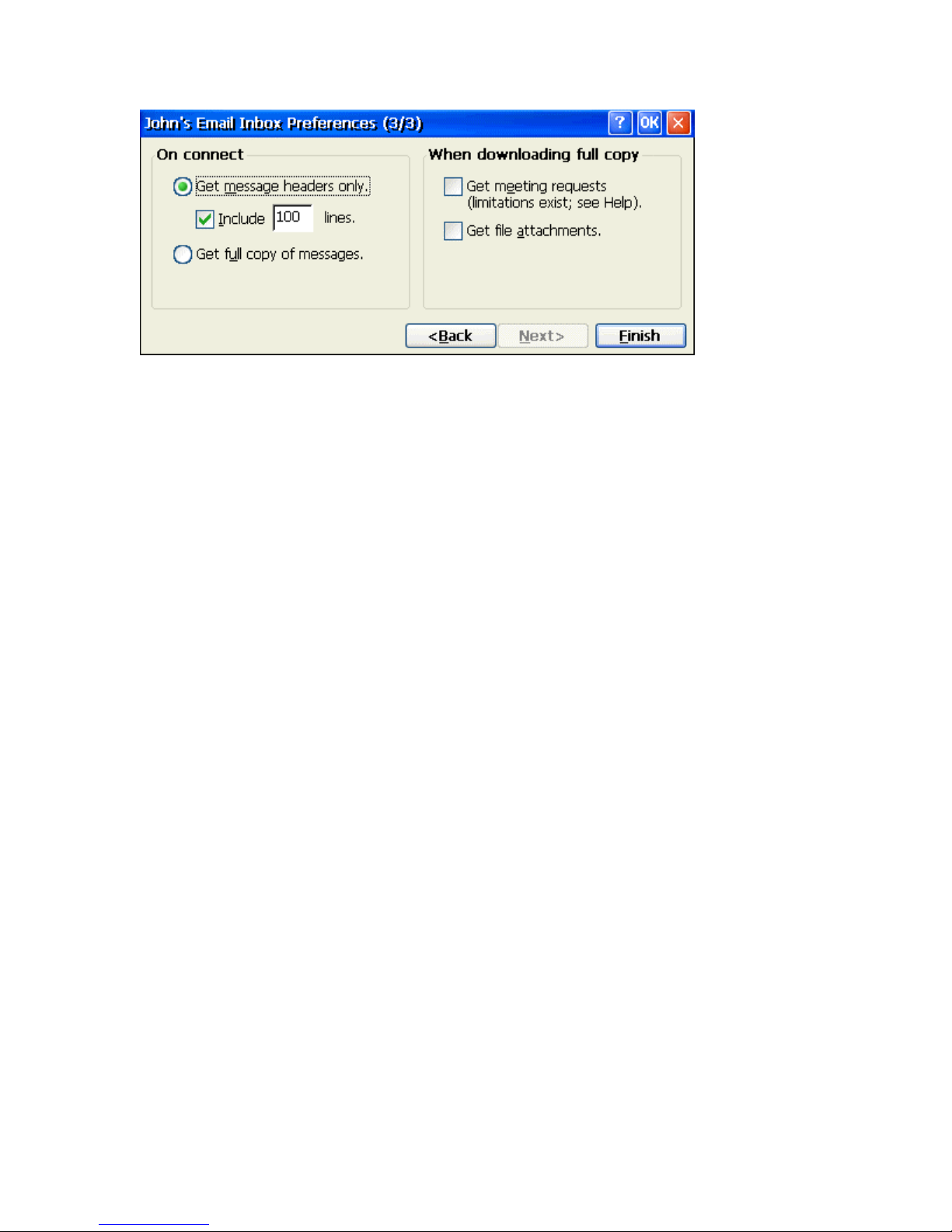
Set Service Inbox Preferences - Setup Wizard Screen 3
If you are adjusting the settings of an existing service, select Services > Options. Select the
service, then select Properties, and then select Next twice. In the Inbox Preferences dialog
box, choose any of the following options and then click on the Finish button to complete the
process.
Get message headers only
Select to save storage space and time by downloading only headers. You can download a
full copy of the message later by selecting the message and then Services > Get Full
Copy
Include <number> lines
Select to set the message length (approximate number of lines) that you want to
download.
Get full copy of messages
Select to receive a full copy of all messages when connecting to a service. In addition to
the entire message body, all options selected under When downloading full copy will be
downloaded as well. Selecting this option increases the amount of time needed to
download messages.
Get meeting requests (POP3 only)
Select to download and store copies of meeting requests when getting full copies of
messages. This setting applies whether you have chosen to download full copies of
messages by default, or if you selectively download full copies of messages by opening
the message and selecting Services > Get Full Copy. Limitations apply.
Get file attachments (POP3 only)
Select to download and save message attachments when getting full copies of messages.
This option may use significant RAM and slow download time. This setting applies
whether you have chosen to download full copies of messages by default, or if you
selectively download full copies of messages by opening the message and selecting
Services > Get Full Copy.
Note: If this option is NOT selected, you will NEVER be able to receive
attachments no matter when you decide to Get Full Copy.
Only synchronize folder hierarchy under Inbox (IMAP4 only)
Select to speed download time by preventing the complete download of the folder list
every time you connect.
Page 93
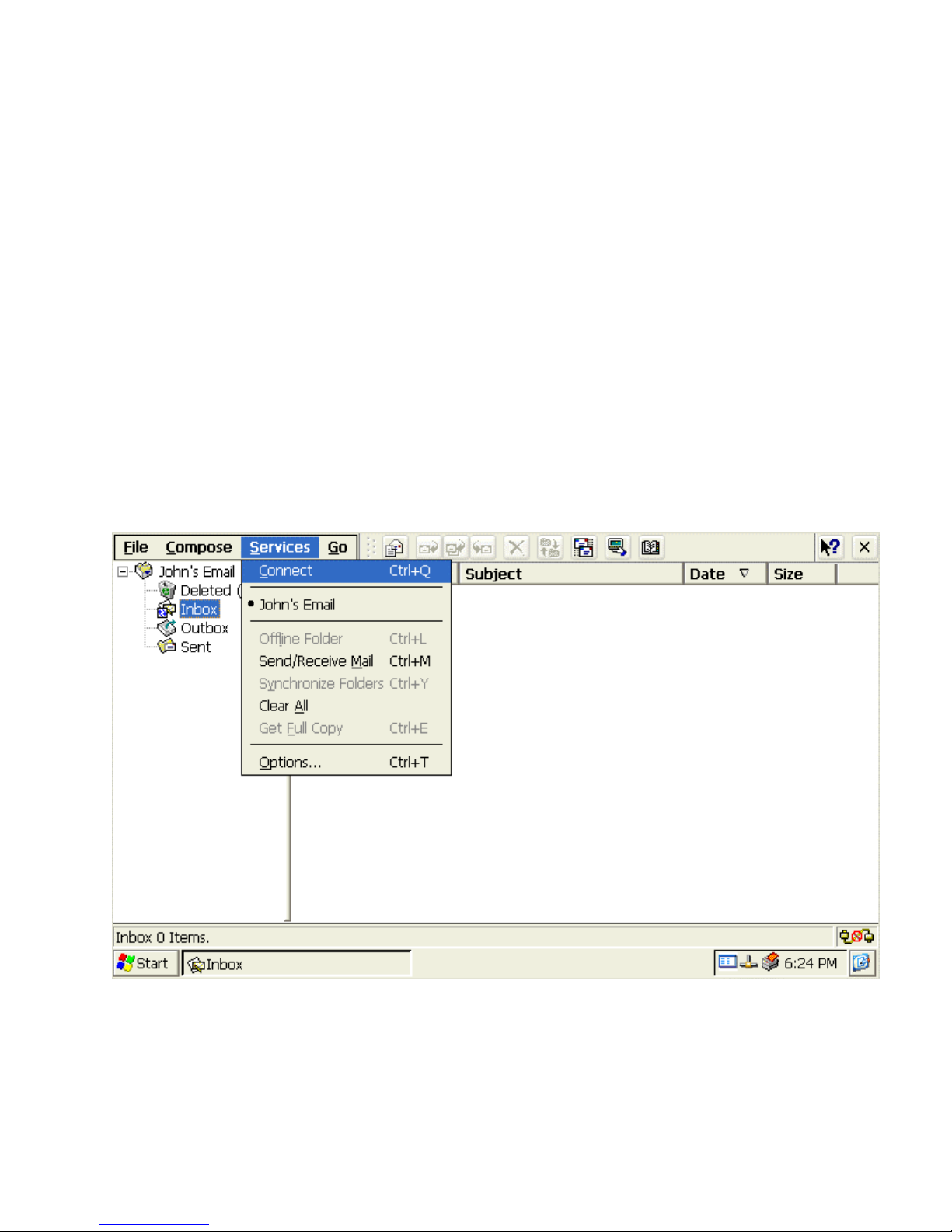
Get file attachments and meeting requests (IMAP4 only)
Select to download and store meeting requests and message attachments when getting full
copies of messages. This setting applies whether you have chosen to download full copies
of messages by default, or if you selectively download full copies of messages by
opening the message and selecting Services > Get Full Copy. Limitations apply.
Only if smaller than (IMAP4 only)
Select to restrict the size of the attachments you download. Set to 10K if you want to
receive meeting requests only.
Download Messages from Server
When you download messages, you need to create two connections: a remote connection and
a mail server connection. The remote connection connects you to your ISP or network. The
mail server connection downloads messages from your mail server to Inbox on your device.
When you select Services > Connect in Inbox, Inbox starts a remote connection using the
connection you specified when setting up the current mail service. If you are already
connected through a remote connection other than the one you specified in the mail service,
you will be asked if you want to use the current connection. If you choose not to, you will
need to disconnect from the current connection before you can check for new messages.
Email Services Menu
1. Select the Services menu and make sure that the service you want to use is
selected (the selected service has a bullet next to it).
2. Select Services > Connect or click on the Connect icon on the toolbar. The
messages on your device and mail server are synchronized: new messages are
downloaded to the device Inbox folder, messages in the device Outbox folder are
sent, and messages that have been deleted on the server are removed from the
device Inbox. Double-click a message in the message list to open it.
Page 94
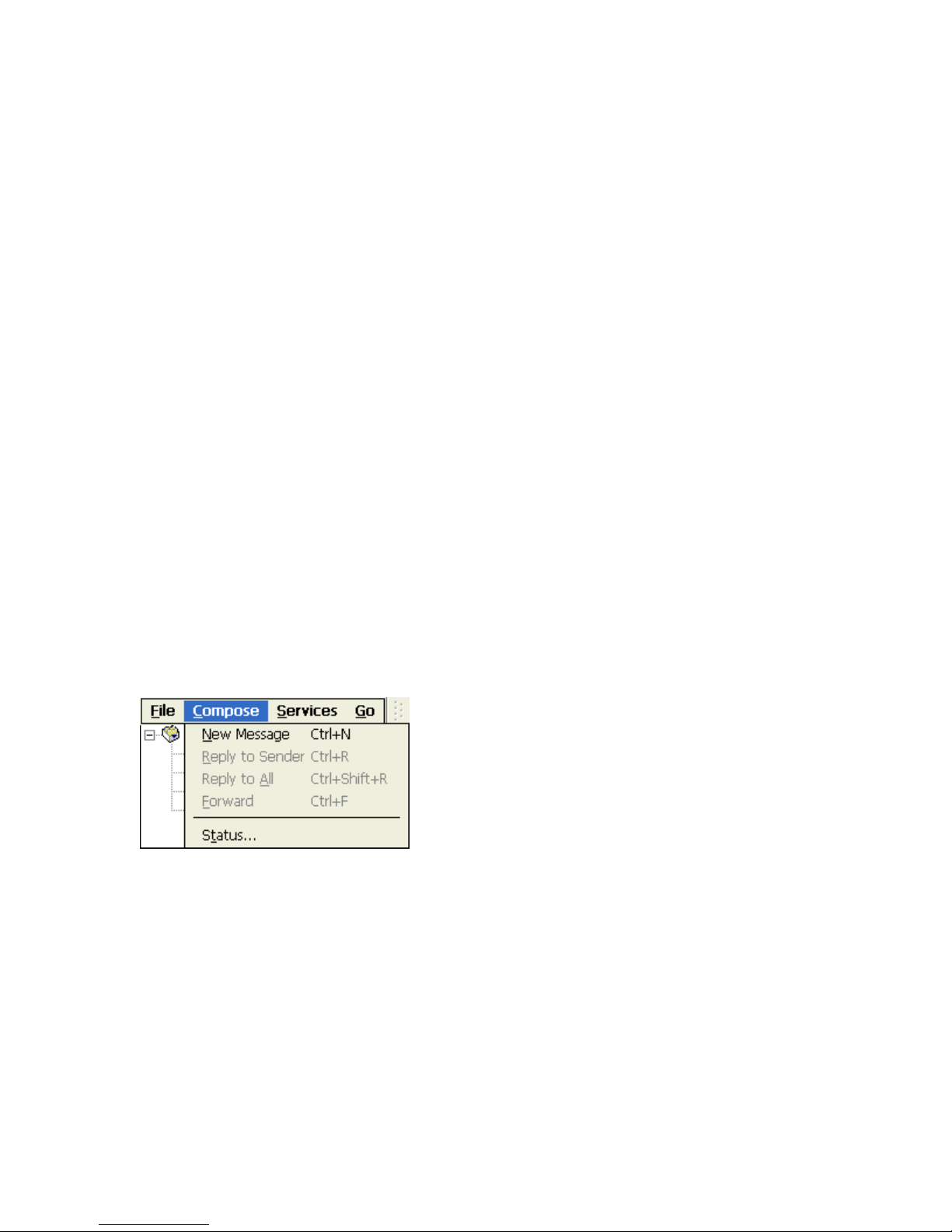
3. If you read a message and decide that you need the full copy, select File > Get
Full Copy while in the message window or Services > Get Full Copy while in list
view. This will also download message attachments and meeting requests if you
have those options selected in the Inbox Preferences dialog box. You can also
choose to download full copies of messages by default.
4. When finished, select Services > Connect to disconnect. If your email service is
via a dial-up connection, you also need to disconnect it by double-clicking the
icon in the status bar and selecting Disconnect.
Note: Receiving entire messages consume storage memory. The size column in the
Inbox list view displays the local size and server size of a message. Even when a message
has been downloaded fully, these numbers may differ because the size of a message can
vary between the server and the device.
Reply to or Forward a message
1. Open the message, and then select Compose > Reply to Sender, Reply to All, or
Forward.
2. Enter your response and select File > Send.
Tips:
1. Selections in the Options dialog box determine whether the original text is included.
2. To see more header information, select the inverted triangle in the lower-right corner
of the header area. Select the triangle again to collapse the header area.
Create a new message
1. From the main email window select Compose > New Message.
2. In the TO: entry box, type in the email address of the intended email recipient.
3. In the CC: entry box, type in the email address of those who you would like to
also send a copy of the intended email.
4. In the Subject: entry box, type in any pertinent information to give the recipients
an idea of what the email is about.
5. In the message body, type in the email text.
6. In the TO entry box, type in the email address of the intended email recipient.
7. Complete the process by selecting File > Send.
Page 95
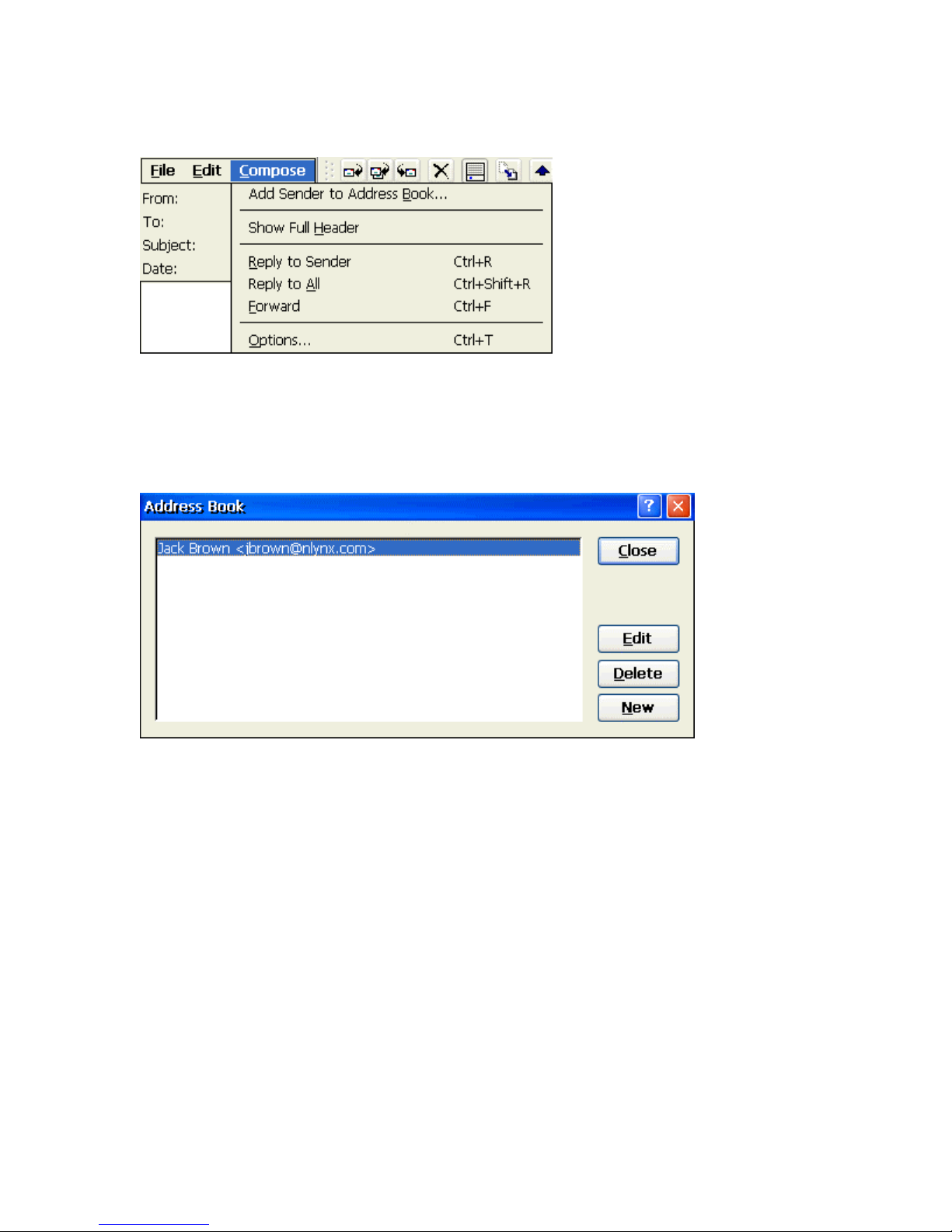
Address Book
Add Sender to Address Book
1. Open the message, and then select Compose > Add Sender to Address Book. A
new contact card will open with the sender's name and e-mail address already
entered.
2. Enter other or edit desired information.
Change the Address Book entries
1. Select Go > Address Book or click on the Address Book icon.
2. To add a new entry, select New.
3. Enter the name you want to type in the To and CC fields of messages in the
Name field.
4. To delete an entry, select it, and then select Delete.
5. To edit an entry, select it, and then select Edit.
Edit Email Options
To edit the global email options or those for a specific service, click on the Options selection
under the Services pull-down menu.
Page 96
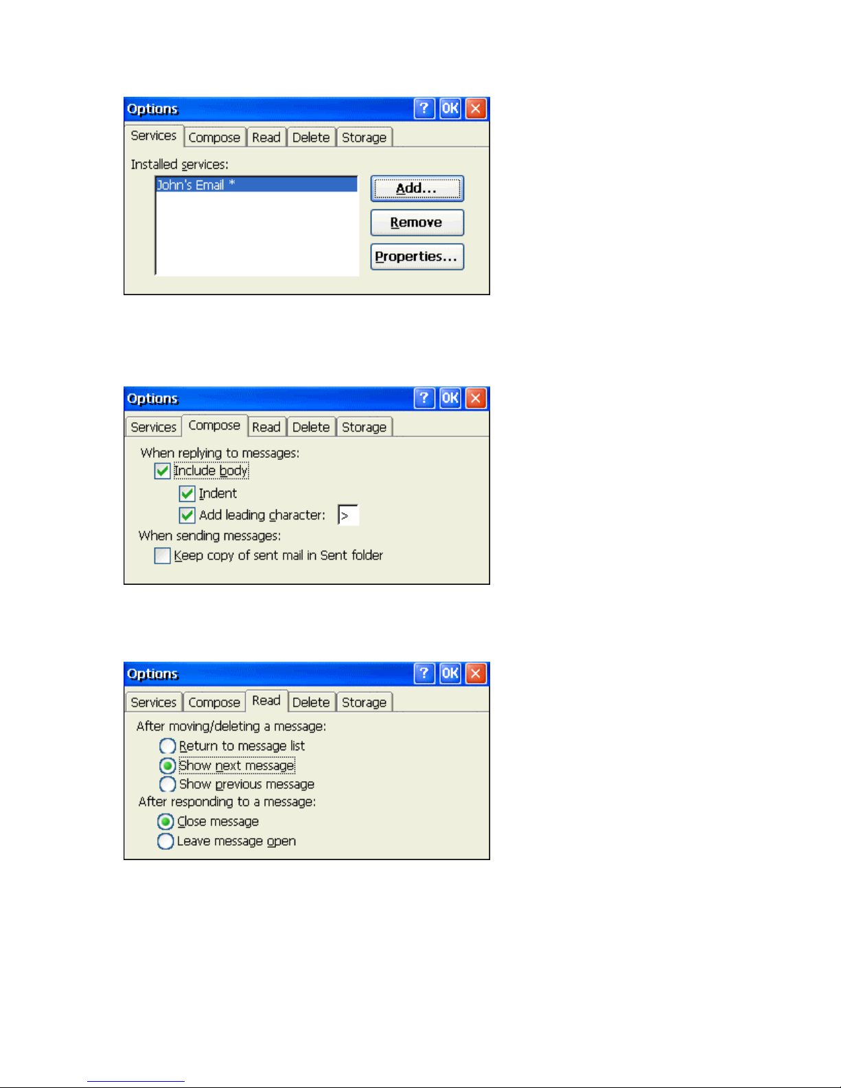
Email Options Window
To edit a specific service, highlight the one intended and click on the Properties button to
open the first window of the Service Setup wizard. Proceed as before editing the desired
information. To edit one of the global email options, click on one of the remaining 4 tabs to
open the appropriate option window.
Compose
Place a check in the appropriate check boxes to enable the indicated option. Clear the
check box to disable the option.
Read
Choose the appropriate radio button to select the desired function for each option.
Page 97
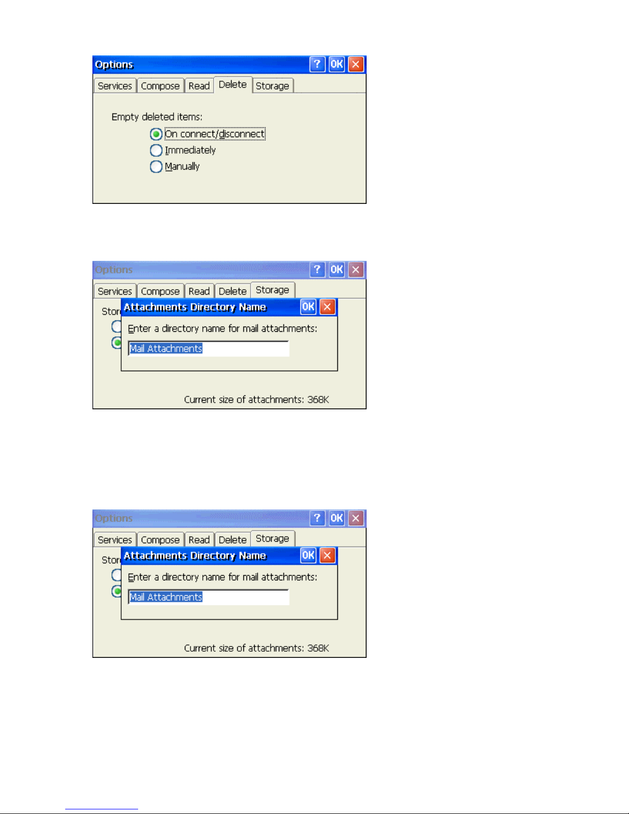
Delete
Choose the appropriate radio button to determine how you want to deal with the Deleted
items folder.
Storage
When downloading messages from the email server, attachments get stored initially by
default into RAM. If desired, attachments can be directed to additional, External
Storage. Currently, the MinIT 6000 supports External Storage via Disk ON Chip
internal flash. Choose the appropriate radio button to determine how you want
attachments to be initially saved.
If you choose External Storage, you will be prompted to provide a directory name for the
email attachments.
Viewing Attachments
The MinIT6000 allows you to view a variety of Microsoft Office file email attachments as well
as certain picture images.
Page 98
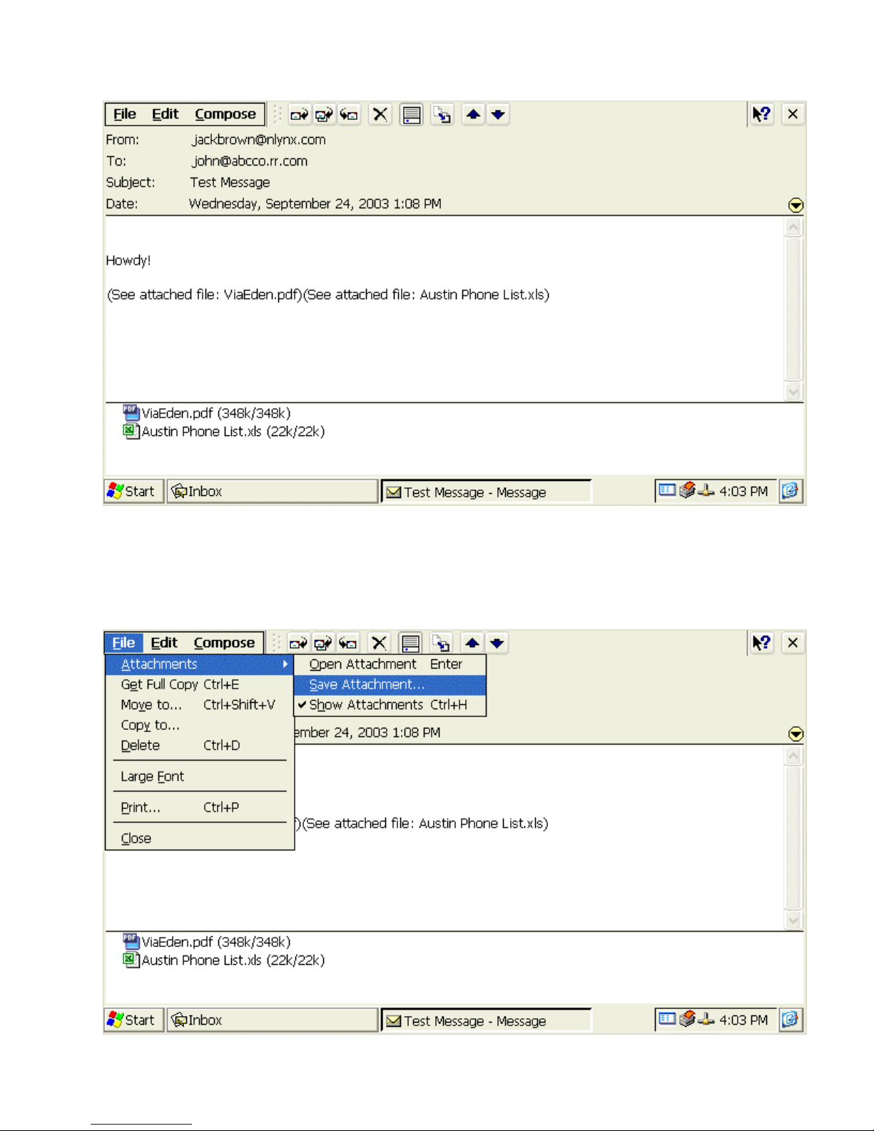
Email Message View Window
To view the attachments, double click on the attachment icon shown towards the bottom of
the screen.
Saving Email Attachments
Email Message View Window
Page 99
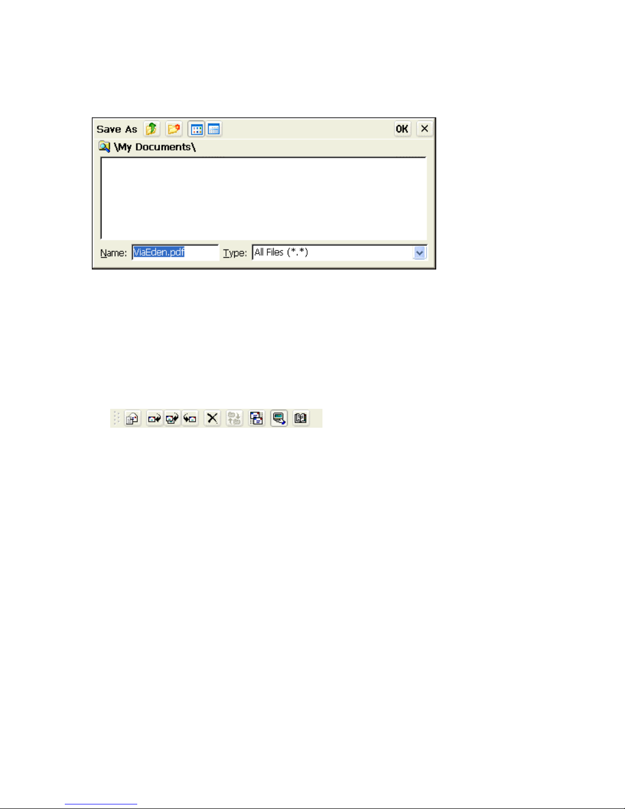
If the Storage option for attachments is set to Internal RAM, you can save the attachment in
a My Documents folder for quick viewing later after the email client has been closed. To
Save the attachment, highlight the attachment and select File > Attachments > Save
Attachment… to bring up the Save As dialog box.
Type in a new name for the attachment if desired and select OK. Now the attachment can be
opened from the appropriate viewer applications by simply selecting File > Open.
Toolbar Buttons
To see the name of a toolbar button, tap or click and hold on the button. Drag the stylus or
cursor off the button so that the command is not carried out.
Toolbar
New Message
Select this button to open a New Message window. This is the same as selecting
Compose > New Message.
Reply
Select this button to Reply to the selected message. This is the same as selecting
Compose > Reply to Sender.
Reply to All
Select this button to Reply to the selected message including all of the recipients email
addresses. This is the same as selecting Compose > Reply to All.
Forward
Select this button to Forward the selected message on to another email address. This is
the same as selecting Compose > Forward.
Delete
Select this button to Delete the selected message. This is the same as selecting File >
Delete.
Page 100

Send / Receive Mail
Select this button to Send any emails ready to go out located in the Outbox or to
download any new emails from the server. This is the same as selecting Services >
Send/Receive Mail.
Connect
Select this button to Connect to the selected email service. This is the same as selecting
Services > Connect.
General Information
After downloading messages into the "inbox" of the email client (with or without attachments),
these messages will remain stored in memory (MinIT6000 RAM) even after the client
application "Inbox" has been closed. If you have NOT power cycled the unit, the next time the
"Inbox" email client is started, these messages can be viewed from the "inbox" prior to
connecting to the Host.
If you power cycle the MinIT6000, ALL previously downloaded email messages will no longer
show up in email client inbox and must be re-downloaded from the host. This includes ANY
additional folders that you might have created from within the client. The next time you connect
to the Host, it will synchronize with the email client and re-download all email messages.
 Loading...