

Page 1

InterLynx/TS
Virtual Private Network and Firewall
User’s Guide
and
Reference Manual
Rev 1.02 July, 2002
Page 2

InterLynx/TS Users Guide
Table of Contents
Introduction
Capabilities, features, functions and specs . . . . . . . . . . . . . . . . . . . 3
Chapter 1
Installing the Hardware . . . . . . . . . . . . . . . . . . . . . . . . . . . . . . . . . 5
Chapter 2
Accessing the IL/TS via Browser . . . . . . . . . . . . . . . . . . . . . . . . . . . 8
Chapter 3
Configuring the IL/TS . . . . . . . . . . . . . . . . . . . . . . . . . . . . . . . . . 11
Chapter 4
IL/TS Network Settings . . . . . . . . . . . . . . . . . . . . . . . . . . . . . . . . . 26
Chapter 5
Configuring the Firewall . . . . . . . . . . . . . . . . . . . . . . . . . . . . . . . . . 28
Chapter 6
More on Firewall Services . . . . . . . . . . . . . . . . . . . . . . . . . . . . . . . . . 42
Chapter 7
Setting up Static Routes . . . . . . . . . . . . . . . . . . . . . . . . . . . . . . . . . . 49
Chapter 8
VPN Configuration . . . . . . . . . . . . . . . . . . . . . . . . . . . . . . . . . . . . . . 52
Chapter 9
VPN Using Shared Secrets . . . . . . . . . . . . . . . . . . . . . . . . . . . 66
Chapter 10
Viewing Logs and Setting up SysLog . . . . . . . . . . . . . . . . . . . . . . . . . 72
Chapter 11
Print Server Configuration . . . . . . . . . . . . . . . . . . . . . . . . . . . . . . . . . 74
2
Page 3
InterLynx/TS
Introduction
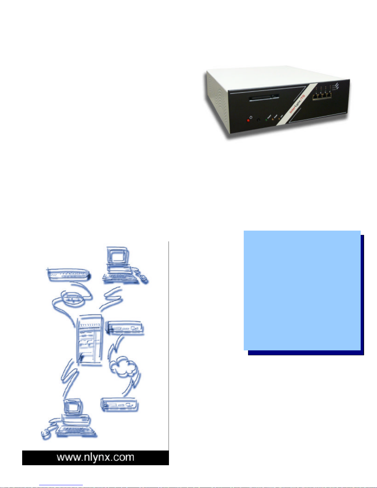
The InterLynx/TS is a Firewall/VPN device
targeted at the remote office environment. It
provides an economical yet powerful firewall for
your Ethernet network. At the same time, its
Virtual Private Network (VPN) capabilities allow
you to use the power of the Internet as the
backbone of your remote office communications,
with the Total Security protection you’d expect
from 3 DES encryption.
If you’ve been struggling with the conflict between secure communications and cost-effective
communications, the solution is here. Low cost communications is now available over the Internet,
while the InterLynx/TS provides the high level of security you need.
It is a Firewall with plenty of firepower. Built on a heavy-duty platform with a high-speed CPU, the
IL/TS has the power to block unwanted traffic, both inbound and outbound. The built-in firewall is
configurable to pass only the traffic you need. IP masquerading (NAT) prevents those on the outside
from seeing the IP addresses on the inside.
It is a VPN.
For data security,
you need more
than just a
firewall. If you
need a costsaving alternative
to leased lines,
the Internet offers
a part of the
solution. DSL or
ISDN links to your
ISP can provide
the bandwidth
you need for several offices, at a fraction of the cost of
multiple leased lines. Your remote offices then only
need to be able to access the Internet (even via dialup) in order to make a connection. The only issue that
remains is that the Internet is a public information
highway, yet you need your data to remain private.
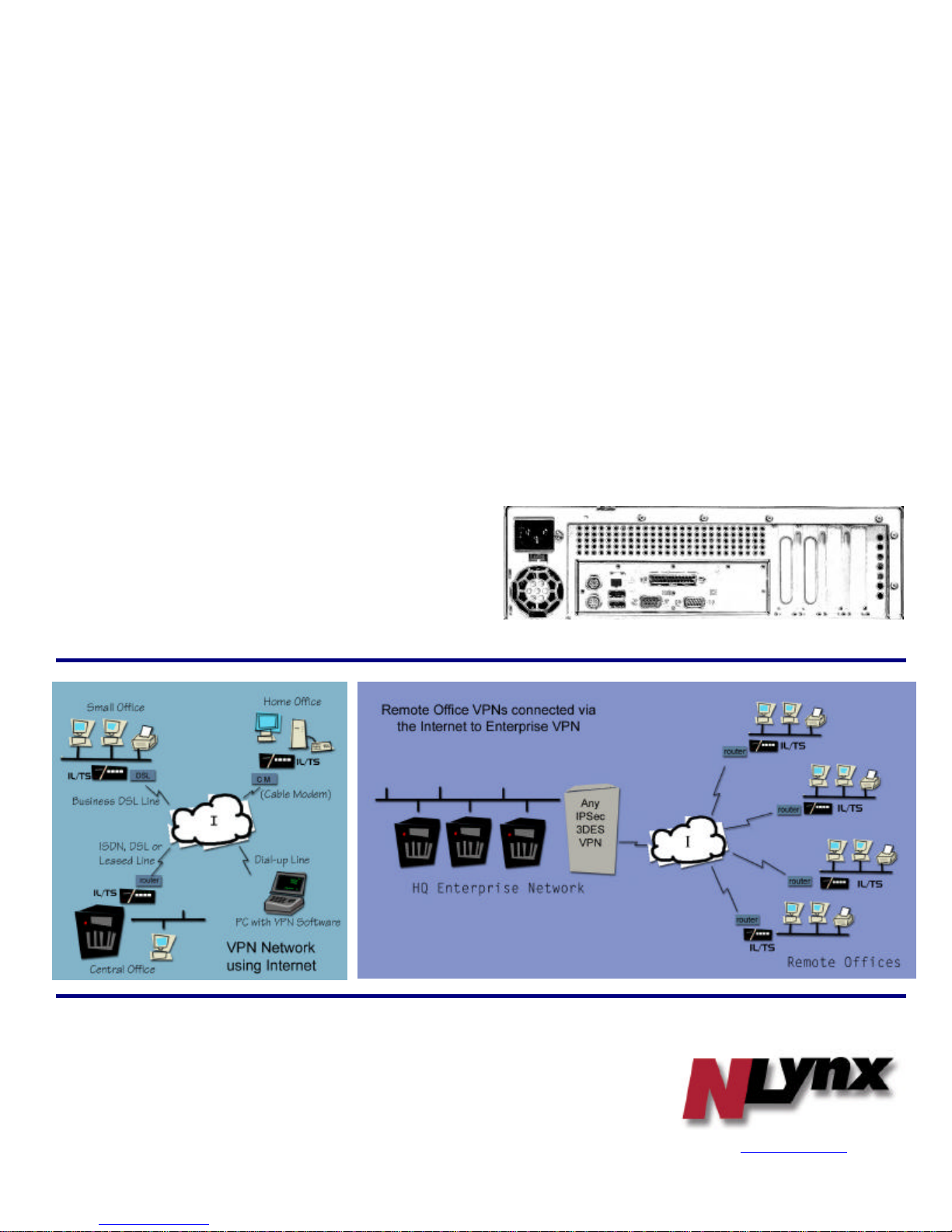
Drop a pair of InterLynx/TS units in between any two
offices and create a VPN. All of the data between the
two offices is 168 bit encrypted. It would take a year
for a supercomputer to break the encryption key, but
ours is changed automatically every two hours
(configurable, of course).
• IPSec standard VPN with 3DES
Encryption, IKE
• Stateful Packet Inspection
Firewall
• DHCP Server
• Built-in 4 port 10/100Mbps
Ethernet Switch
• NAT, PAT
• PPP Dial backup
• Built-in Print Server
• SSH, PGP, and Windows XP Pro
VPN Client support
• Heavy duty hardware for extra
reliability
Page 4
Headquarters
Applications:
Firewall method: Stateful Packet Inspection
Specifications:
Rev 07/02
Part Numbers:
InterLynx/TS: 301-0901-01
Spare Flash: 263-0076-04
SSH VPN Client: 301-9701-01
Wireless Option: Available Q3 2002
Package includes: InterLynx/TS unit, CD ROM
(User Guide/Reference Manual), Power Cord, two
Ethernet cables, Quick Install Guide.
Physical
Dimensions: 12.5” W x 3.75” H x 14.5” D
Weight: 11.0 Lbs, 5.1 Kg
Power: 110/220 VAC, Switchable
Operating Temperature: 0 to 40 C
Operating Humidity: 10 – 90% non-condensing
CPU: 633Mhz Intel
Memory: 64Mb
OS: Hardened Linux
Flash Drive: 32Mb
LAN Protocol: IP
VPN protocol: IPSec
Encryption: 3DES – MD5
Authentication methods: RSA, Shared Secrets
Management: Browser based (IE 4 & up, Netscape
4 & up)
Ports:
♦ 1 10/100 RJ45 Ethernet port (rear) for connection
to external network.
♦ 4 10/100 RJ45 Ethernet ports (front) for
the local network.
♦ 1 Serial port (PPP dial backup).
♦ 1 Parallel (print server) port
Built-in 4 Port 10/100Mbps Ethernet Switch:
Standards: IEEE 802.3u 100BaseTX,
IEEE 802.3 10BaseT
Media: 100 Ohm Cat. 5 UTP
Switching Method: Store and Forward
Mode: Auto-negotiated 10/100Mbps, Full/Half
Duplex
LEDs: 3 per port – FDX, Link, 10/100Mbps
NLynx Technologies, Inc.
8313 Hwy 71 West
Austin, TX 78735
Tel: 512 301-8000
Sales: 800-328-2696
NLynx Northern Europe
4th Floor, The Graftons
Stamford New Road
Altrincham
Cheshire WA14 IDQ
United Kingdom
Tel: 44 (0) 161 928 7014
Fax: 44 (0) 161 928 7015
NLynx Southern Europe
6 Boulevard Henri Sellier
Tour Ventose
92150 Suresnes
France
Tel: 33 (0) 1 41 44 91 00
Fax: 33 (0) 1 41 44 91 01
Back View
www.nlynx.com
email: [email protected]
Page 5
InterLynx/TS User’s Manual_________________________________________________________________
Chapter 1
_______________________________________________Installing InterLynx/TS Hardware
1. Unpack the InterLynx/TS unit from its shipping carton.
Verify that the InterLynx/TS shipping carton contains the following parts:
ü InterLynx/TS Unit
ü Power Cord
ü User’s Manual (CD ROM)
ü Ethernet Cable
ü Quick Install Guide
2. Hardware Setup for the InterLynx/TS
Section A
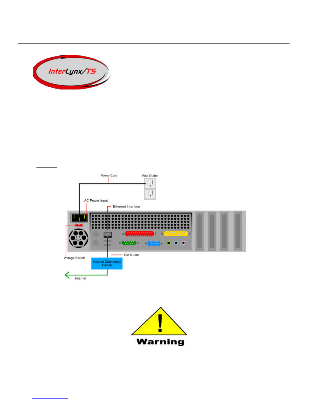
Make certain that the voltage switch is set appropriately for the power source you intend to use. Damage and/or injury could
Back panel of the InterLynx/TS firewall
result if this unit’s voltage switch is set incorrectly.
1-1
Page 6
InterLynx/TS User’s Manual_________________________________________________________________
Refer to figure 1-1 above to reference the following steps:
1) Connect the CAT 5 cable to the Ethernet interface on the back on the InterLynx/TS.
2) Connect the other end of the CAT 5 cable to the Internet connection device (i.e. router, cable modem, etc.).
3) Set the voltage switch to the appropriate setting for your area. An improper setting will damage the power supply and
may cause personal injury.
4) Connect the female end of the power cord into the AC power connector on the back of the InterLynx/TS.
5) Plug the male end of the power cord into a wall outlet.
Section B
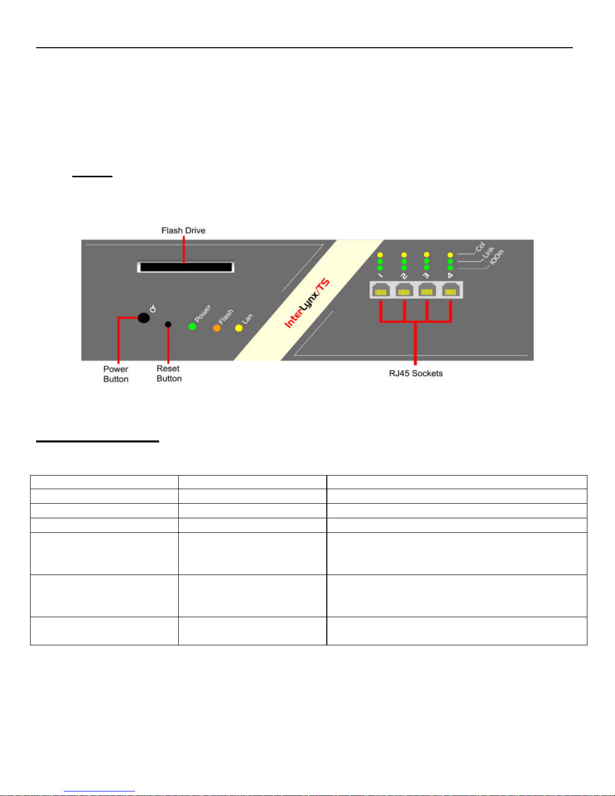
Connect other network devices such as terminals or hubs to the Ethernet interfaces (RJ45 Sockets) on the front of the
InterLynx/TS unit using CAT 5 lines.
Front panel controls for the InterLynx/TS firewall
Troubleshooting
Diagnostic LED indicators
LED State Indication
Power On ( green ) Unit is powered on
Flash On/Flashing ( amber ) Activity on Flash card
LAN On ( amber ) Internal Network is functioning properly
FDX/Col On ( amber )
Off
Flashing ( amber )
Act/Link On ( green )
Off
Flashing ( green )
100m On
Off
Symptom: Link indicator does not light up after making a connection.
Cause: Network interface or network cable is defective.
Solution: Verify that the switch and attached devices are powered on. Be sure the cable is correctly
plugged into both the switch and corresponding device. Verify that the proper cable type is used
and its length does not exceed specified limits. Each twisted-pair cable should not exceed 100m
(328 ft.). Check the adapter on the attached device and cable connections for possible defects.
Port is operating in full-duplex mode
Port is operating in half-duplex mode
Port has detected a collision on this port
Port has a valid network connection
Port has not established any network connection
Port is transmitting/receiving data
Port is operating at 100mb
Port is operating at 10mb
1-2
Page 7
InterLynx/TS User’s Manual_________________________________________________________________
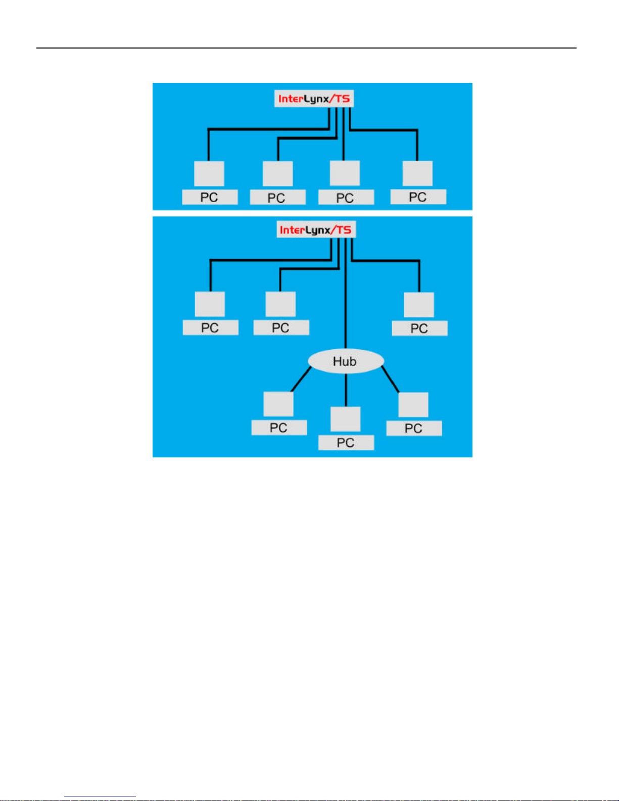
Example Topologies
1-3
Page 8
InterLynx/TS User’s Manual_________________________________________________________________
Chapter 2
Configuring the PC for Accessing the InterLynx/TS
Configuring the TCP/IP properties on the PC
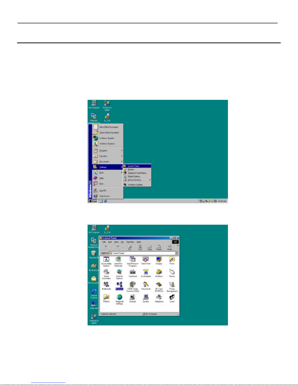
Use the steps below to bring up the TCP/IP properties for the PC:
1. On the PC that will communicate with InterLynx/TS press Start, and then highlight Settings, and then
highlight Control Panel (Win95, Win98, or ME) or Network and Dial-up Connections (Win2000 and
XP).
2. At this point the Control Panel window is now visible on the screen. Double Click on the Network icon.
2-1
Page 9
InterLynx/TS User’s Manual_________________________________________________________________
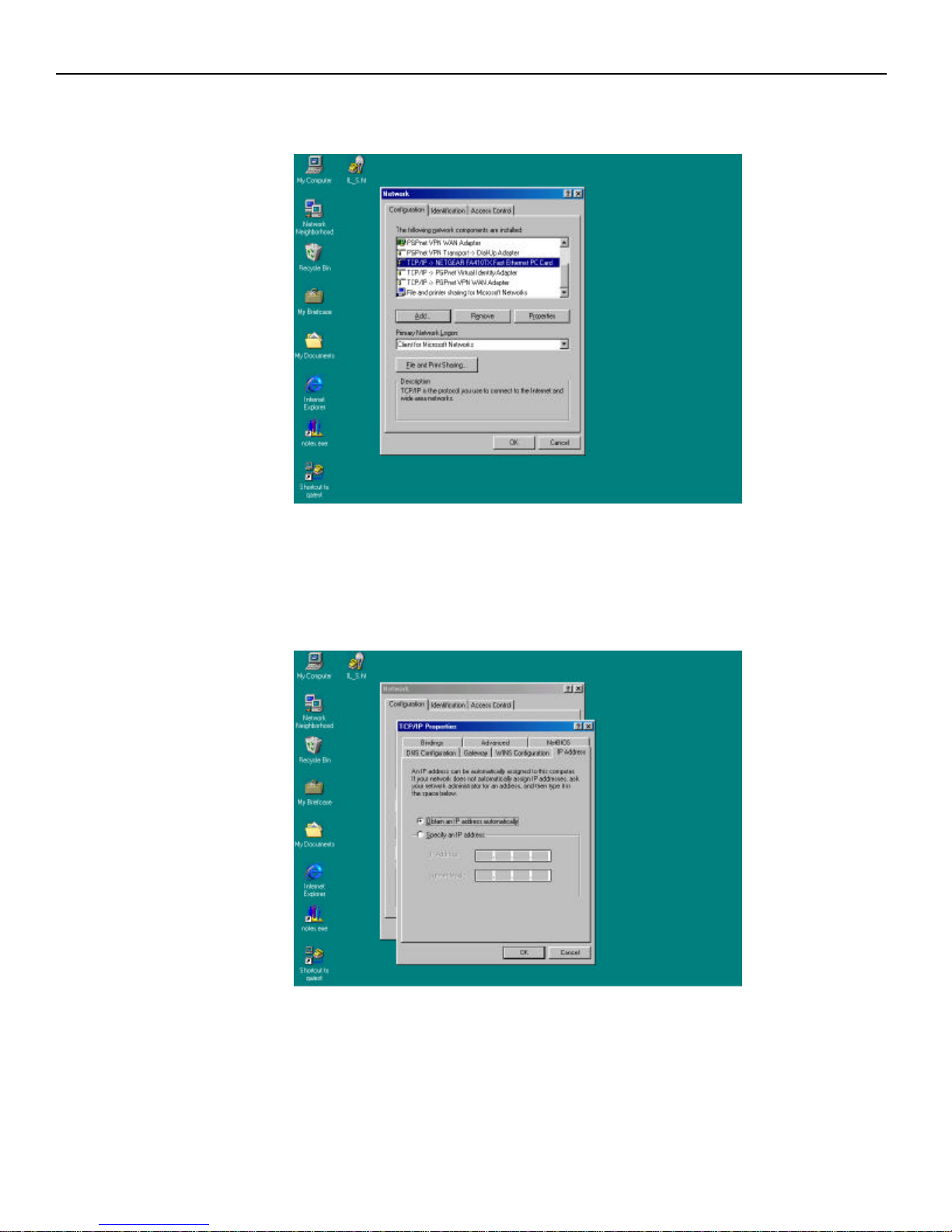
3. down until you locate the Ethernet card on the PC and make note of the name and then highlight the
TCP/IP for that Ethernet card and press the Properties button.
4. The TCP/IP properties window should now be displayed. If the InterLynx/TS will be acting as the
DHCP Server (A server that distributes IP address) for the network, then make sure the Obtain IP
Address automatically radio button is selected. If the InterLynx/TS is not going to be the DHCP
Server then go to Step 5.
2-2
Page 10
InterLynx/TS User’s Manual_________________________________________________________________
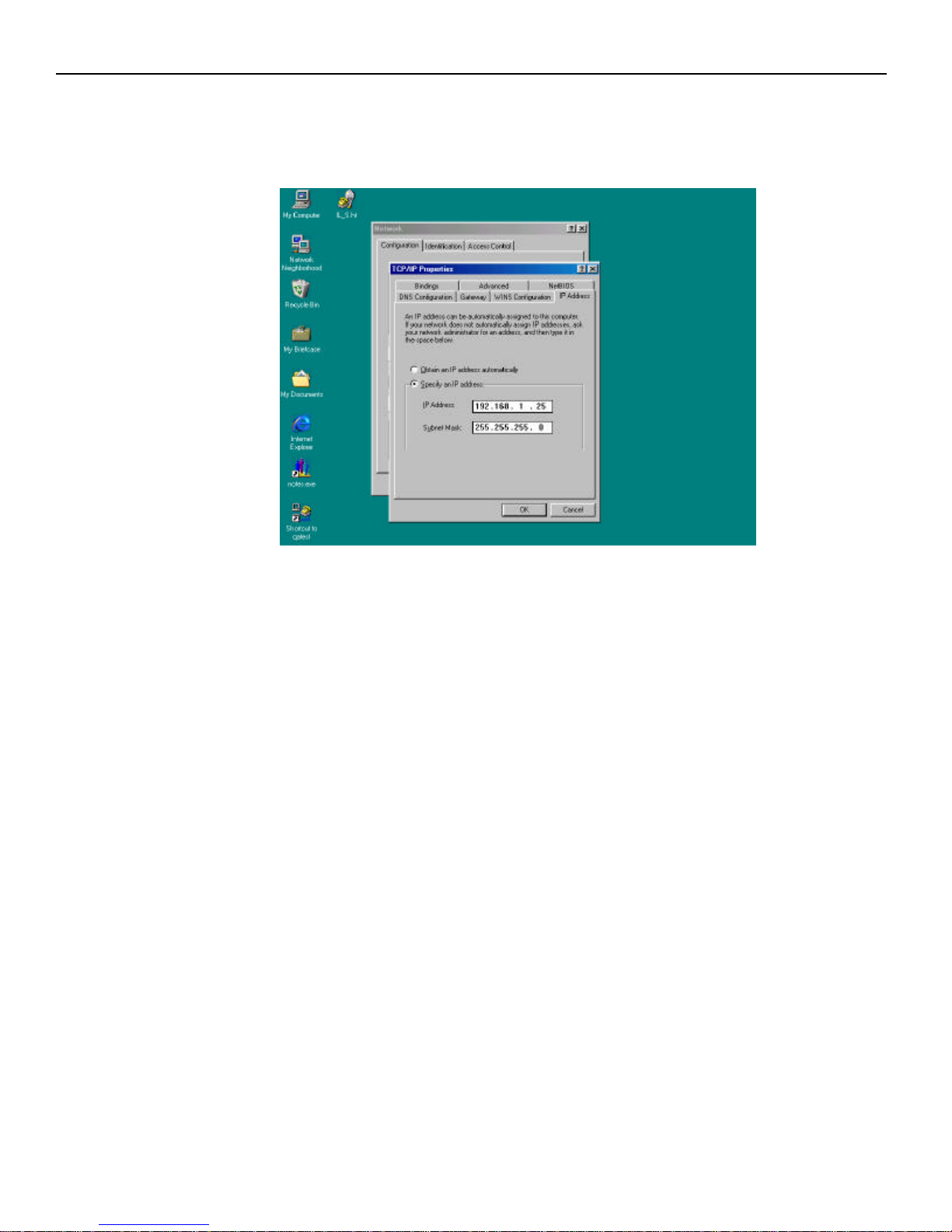
5. If you would like to manually assign an IP address to the PC make sure the Specify an IP address radio
button is selected. The default IP address for the InterLynx/TS is 192.168.1.254 with a /24 subnet
(255.255.255.0). The IP address given to the PC must be on the 192.168.1.0 network in order to
communicate with the InterLynx/TS.
6. Reboot PC for IP changes to take effect.
2-3
Page 11
InterLynx/TS User’s Manual_________________________________________________________________
Chapter 3
System Settings and Remote Configuration Setup
Part I – Accessing the InterLynx/TS Via Web Browser
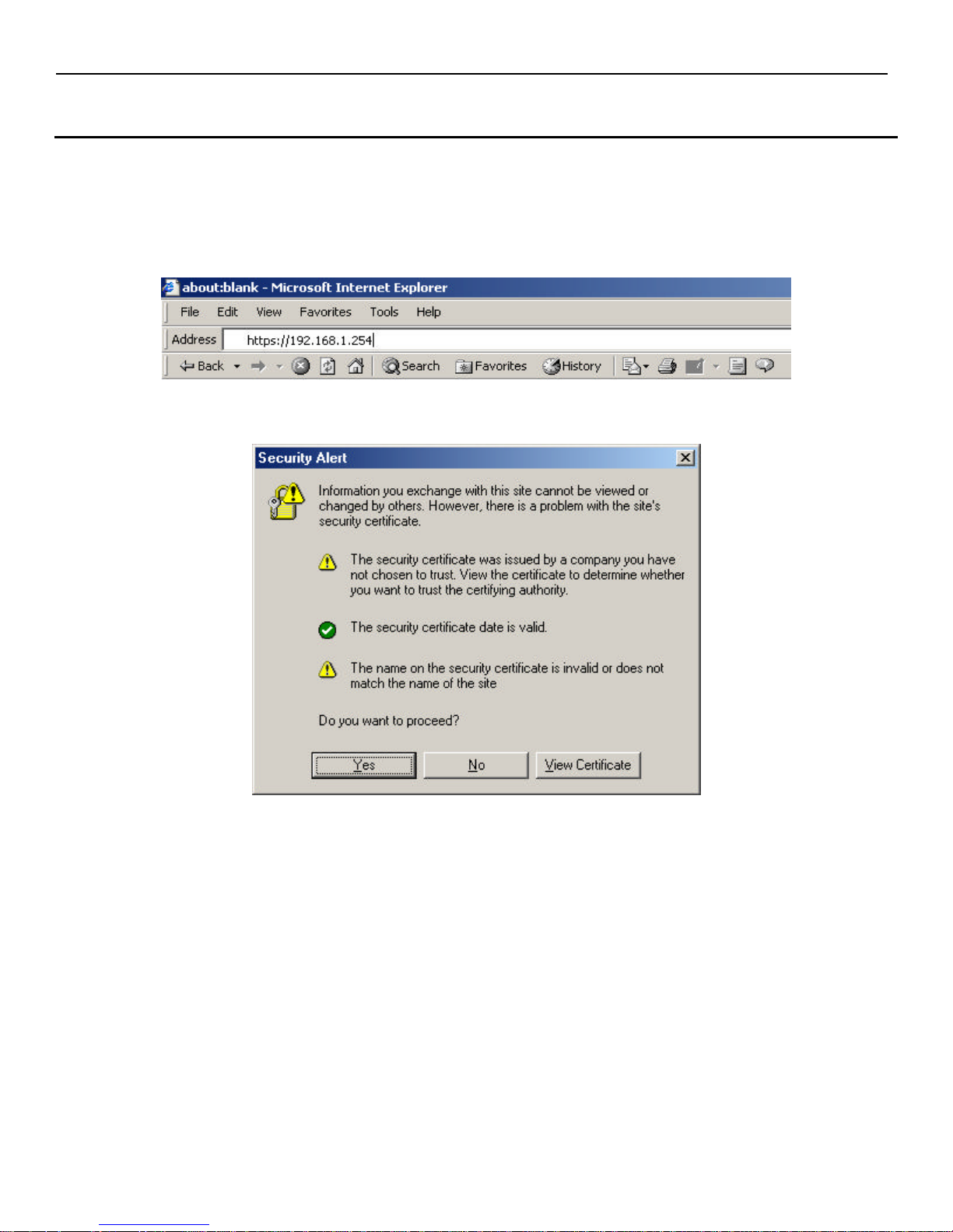
The first step in connecting to the InterLynx/TS is to open a browser window and type in the URL of the unit as
shown below. Once the URL has been entered press ‘Return.’ The example below uses the URL
‘https://192.168.1.254.’
When ‘Return’ is pressed the following box is displayed in Internet Explorer:
Click ‘Yes’ to continue.
3-1
Page 12
InterLynx/TS User’s Manual_________________________________________________________________
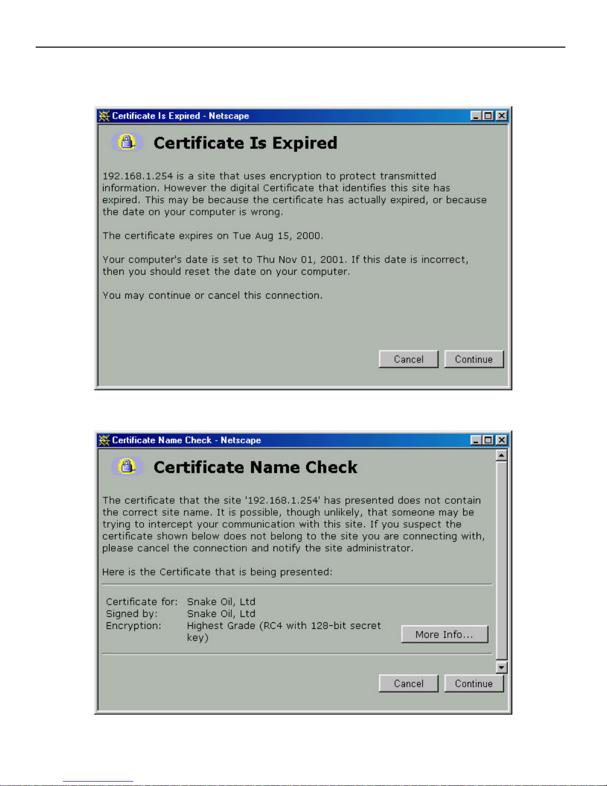
For Netscape, the following are displayed (appearance differs slightly based on version):
Press the ‘Continue’ button when the box below is displayed.
When the box below is displayed press ‘Continue.’
3-2
Page 13
InterLynx/TS User’s Manual_________________________________________________________________
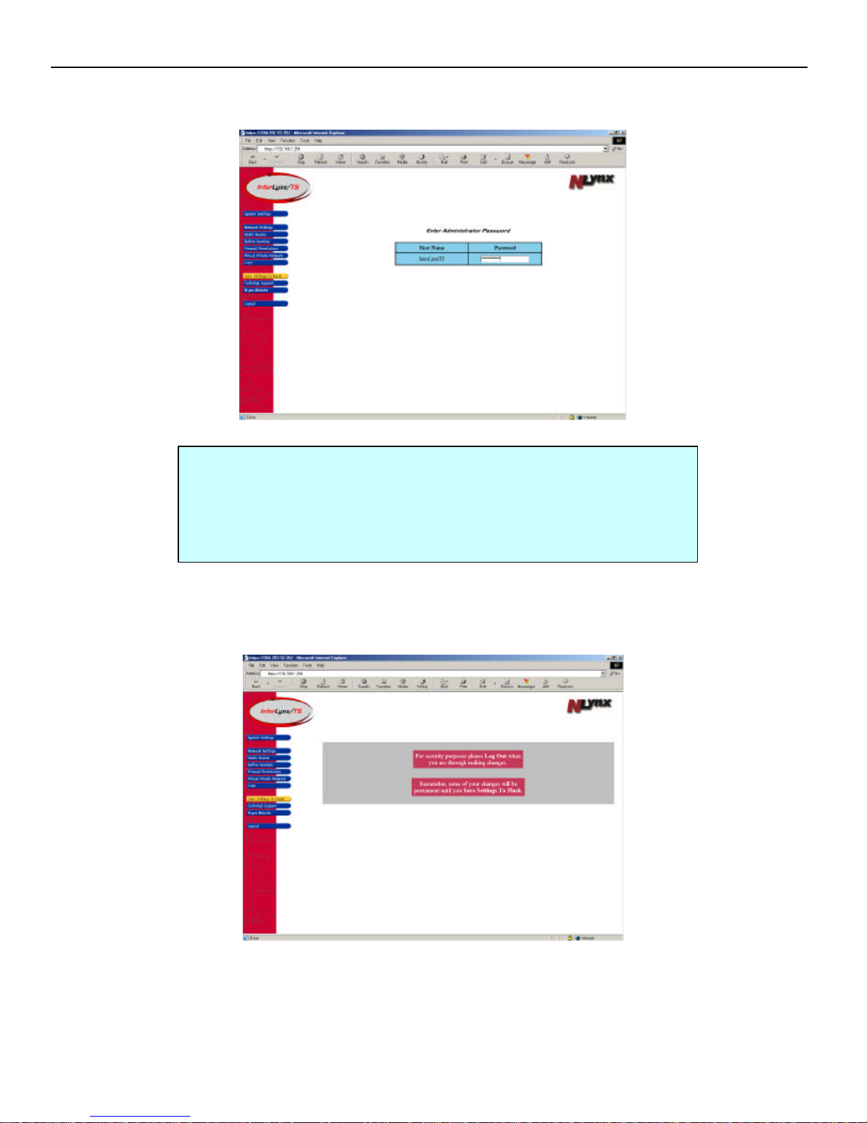
1. The first screen to appear is the InterLynx/TS login screen. Here, you will enter the default password,
changemenow, and press the ‘Enter’ key.
Troubleshooting a failed browser connection to the InterLynx/TS:
1. There is already a device on the LAN at address 192.168.1.254. Either the
IL/TS or the other device needs to be isolated until the IP configuration can
be changed.
2. The PC that is being used to connect to the IL/TS via the web browser does
not have an IP address or IP address configured correctly.
2. Upon successfully logging onto the InterLynx/TS, an introduction page is displayed with a menu of
items on the left side of the screen.
3-3
Page 14
InterLynx/TS User’s Manual_________________________________________________________________
Part II – Changing The System Password
After logging into the InterLynx/TS:
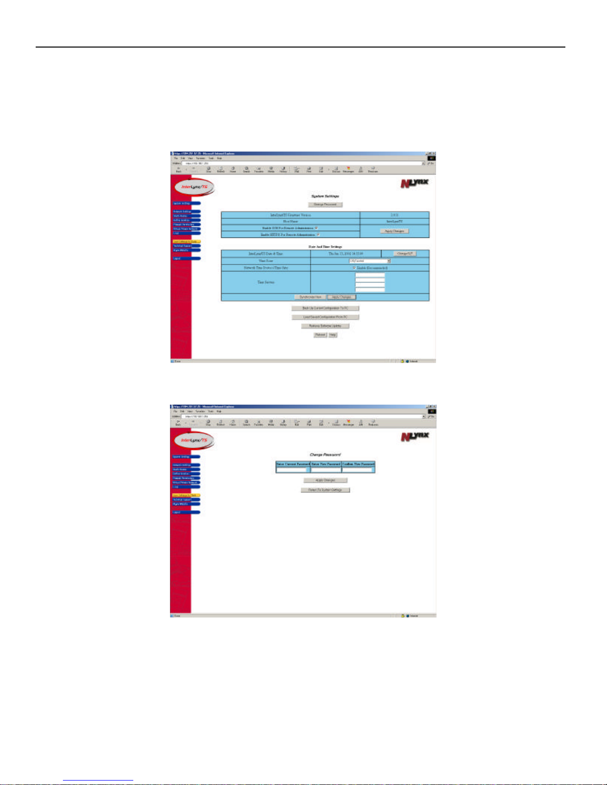
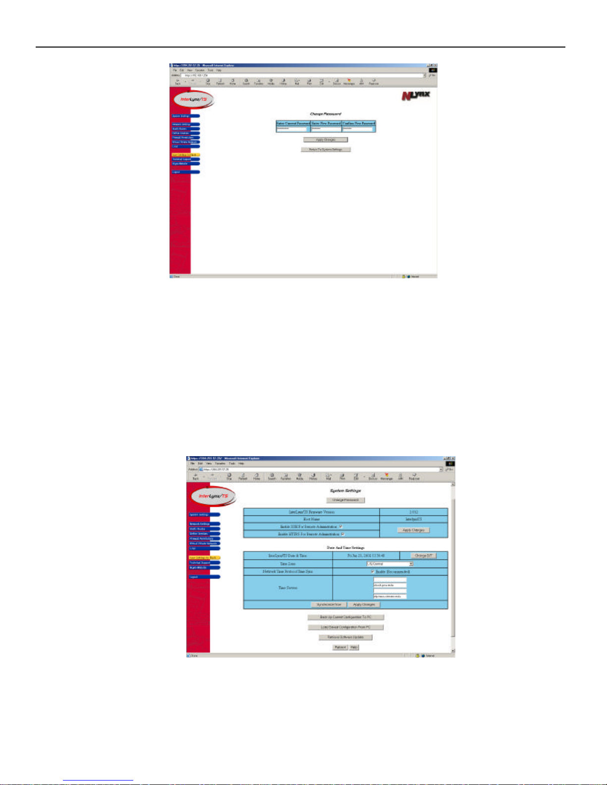
1. Change the System Password:
a. Click on System Settings in the left menu area.
b. Click the Change Password button, this will bring up the Change Password page.
c. Under Current Password, type in changemenow.
d. Under Enter New Password, type in your new password and write it down.
NOTE: Password must be at least 8 characters in length.
e. Under Confirm New Password, make sure you type in your new password again correctly.
3-4
Page 15
InterLynx/TS User’s Manual_________________________________________________________________
f. Click on the Apply Changes button. The System Settings page will then reappear.
Important: You have now temporarily changed the system password. In order to make this change
permanent, you must click on the yellow Save Settings to Flash button on the left side of the screen.
Any configuration changes made to the unit are temporary until the Save Settings to Flash button is
clicked.
The System Settings page also displays the version of Firmware running on the unit, and displays the
Host name for the InterLynx/TS. Remote Administration (HTTPS and/or SSH) to the InterLynx/TS
can be configured along with the Date and Time. Please refer to the following sections on how to
configure these options.
3-5
Page 16
InterLynx/TS User’s Manual_________________________________________________________________
Part III – Configuring Remote Administration to the InterLynx/TS
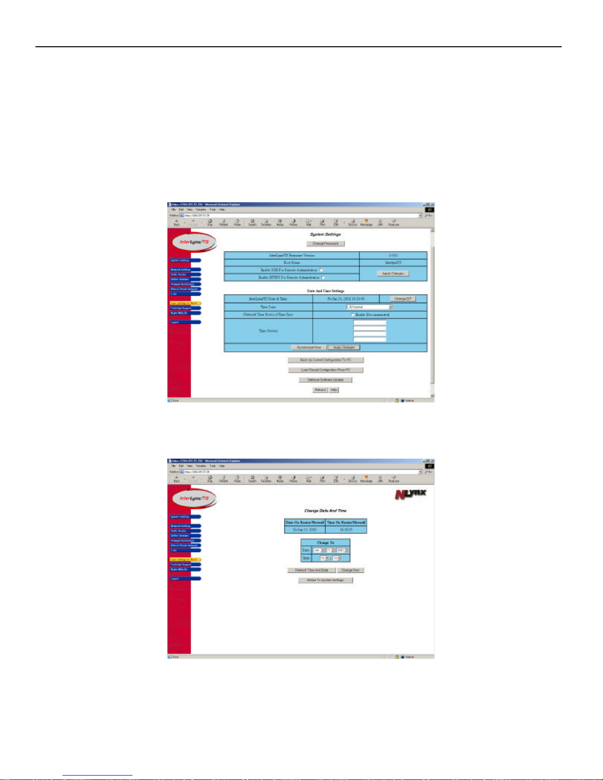
1. To temporarily enable Remote Administration over the Internet, check one or both of the boxes as noted
below:
• Enable SSH For Remote Administration – Allows a secure shell connection (command line).
• Enable HTTPS for Remote Administration – Allows a secure Web connection for Remote
Administration.
2. Check the appropriate boxes to activate the selected services, then press the Apply Changes button.
3. For Security purposes, The Enable SSH Remote Administration and Enable HTTPS Remote
Administration services, should be disabled except when needed for remote (from the Internet)
configuration.
Part IV – Date and Time Settings
1. The Date and Time setting can be changed by pressing the Change D/T button.
2. Once the changes are made press the Change Now button, and when the screen refreshes press the
Return to System Settings button.
3-6
Page 17
InterLynx/TS User’s Manual_________________________________________________________________
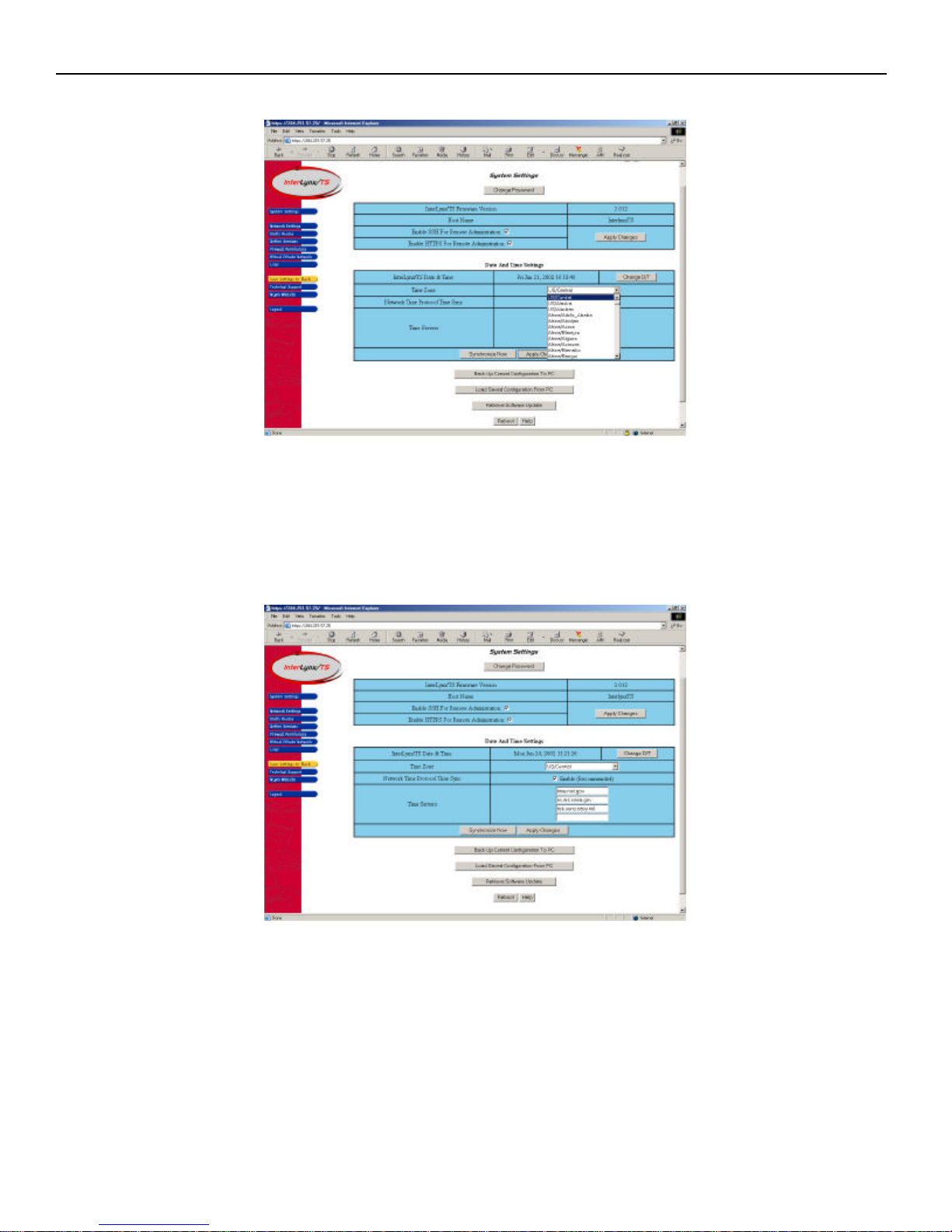
3. Make sure the correct Time Zone is chosen for the InterLynx/TS, by using the pull-down menu.
4. The next step is enabling (recommended) the Network Time Protocol Time Sync, by checking the
enable box. In the Time Server fields the URLs for of the NTP Servers need to be added. Here are 3
Time Server URLs that can be used:
a. ns.arc.nasa.gov (NASA)
b. time.nist.gov (NIST)
c. tick.usno.navy.mil (US NAVAL Observatory)
5. Press Apply Changes when finished. Then the yellow Save Settings To Flash button to make the
changes permanent.
3-7
Page 18
InterLynx/TS User’s Manual_________________________________________________________________
Part VI – Saving the current configuration on the InterLynx/TS
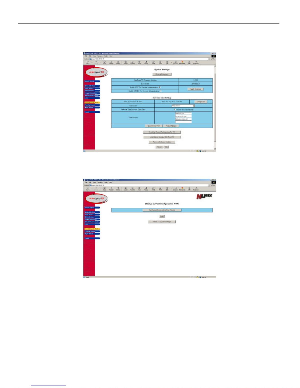
1. To save the current InterLynx/TS configuration file, press the Back Up Current Configuration To PC
button from the System Settings page.
2. The Backup Current Configuration To PC page should appear. Now press the Get Current
Configuration From Router button.
3-8
Page 19
InterLynx/TS User’s Manual_________________________________________________________________
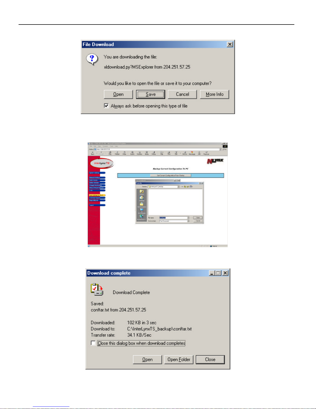
3. A File Download box will appear, choose Save.
4. After choosing Save, the Save As window will appear, allowing the file to be saved to any Directory on
the PC or to a floppy disk. Select the location to save the backup file, and click on the Save button.
5. The Download complete dialogue box will appear, click the Close button.
3-9
Page 20
InterLynx/TS User’s Manual_________________________________________________________________
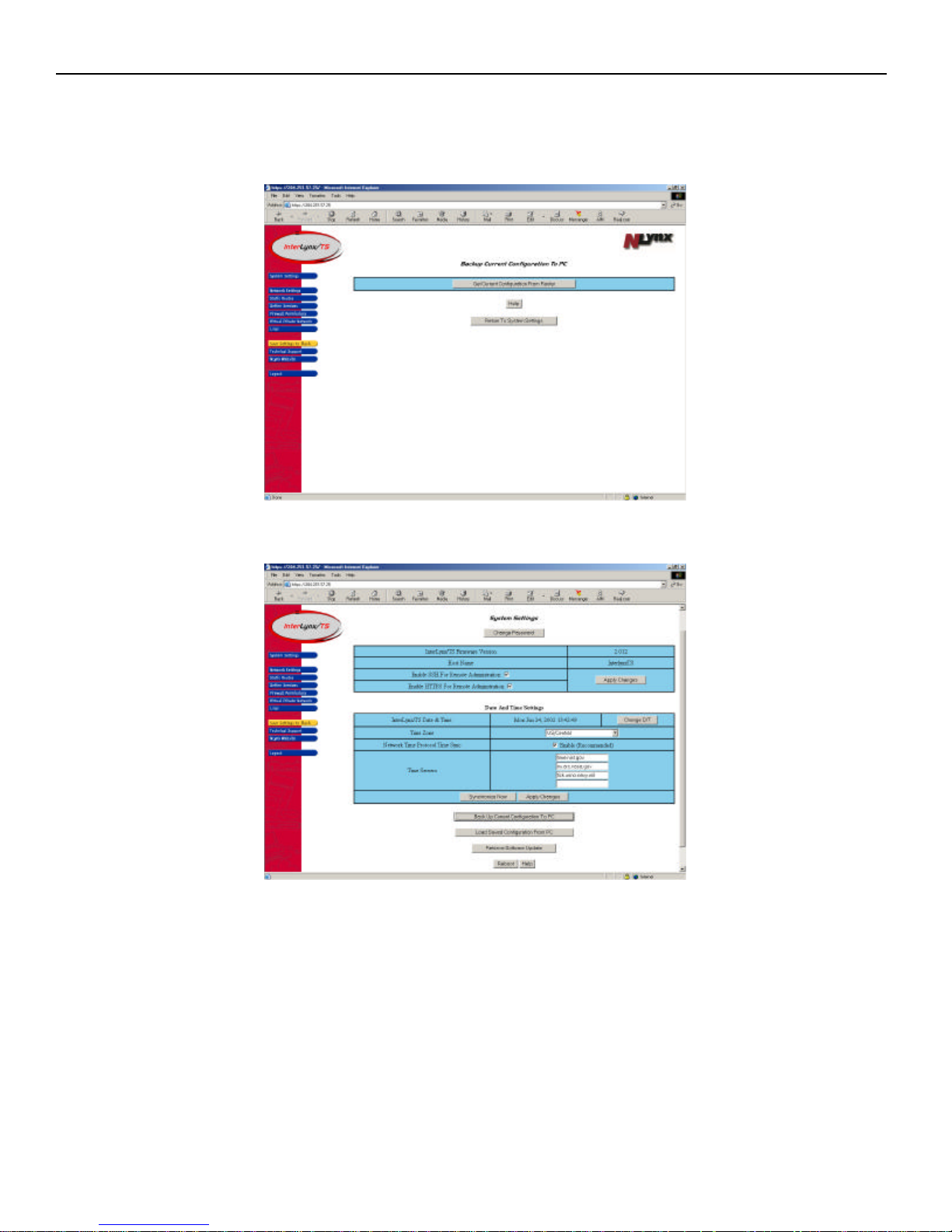
6. The saving of a configuration file to a PC is now complete. The Backup Current Configuration To PC
window will now appear, click on Return To System Settings.
7. The Backup Current Configuration To PC window will appear, press the Return To System Settings
button.
8. The System Settings page will now appear.
3-10
Page 21
InterLynx/TS User’s Manual_________________________________________________________________
Part VII – Restoring a Saved configuration to the InterLynx/TS
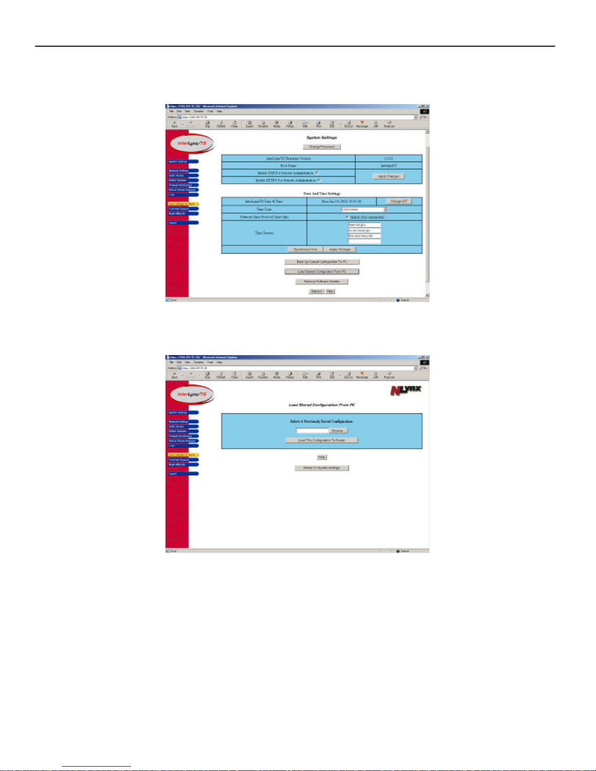
1. To Restore a saved configuration from a PC to the InterLynx/TS, press the Load Saved Configuration
From PC button on the System Settings page.
2. The Load Saved Configuration From PC page will appear, click on the Browse button to locate the
saved configuration file on the PC or type in the location of the file..
3-11
Page 22
InterLynx/TS User’s Manual_________________________________________________________________
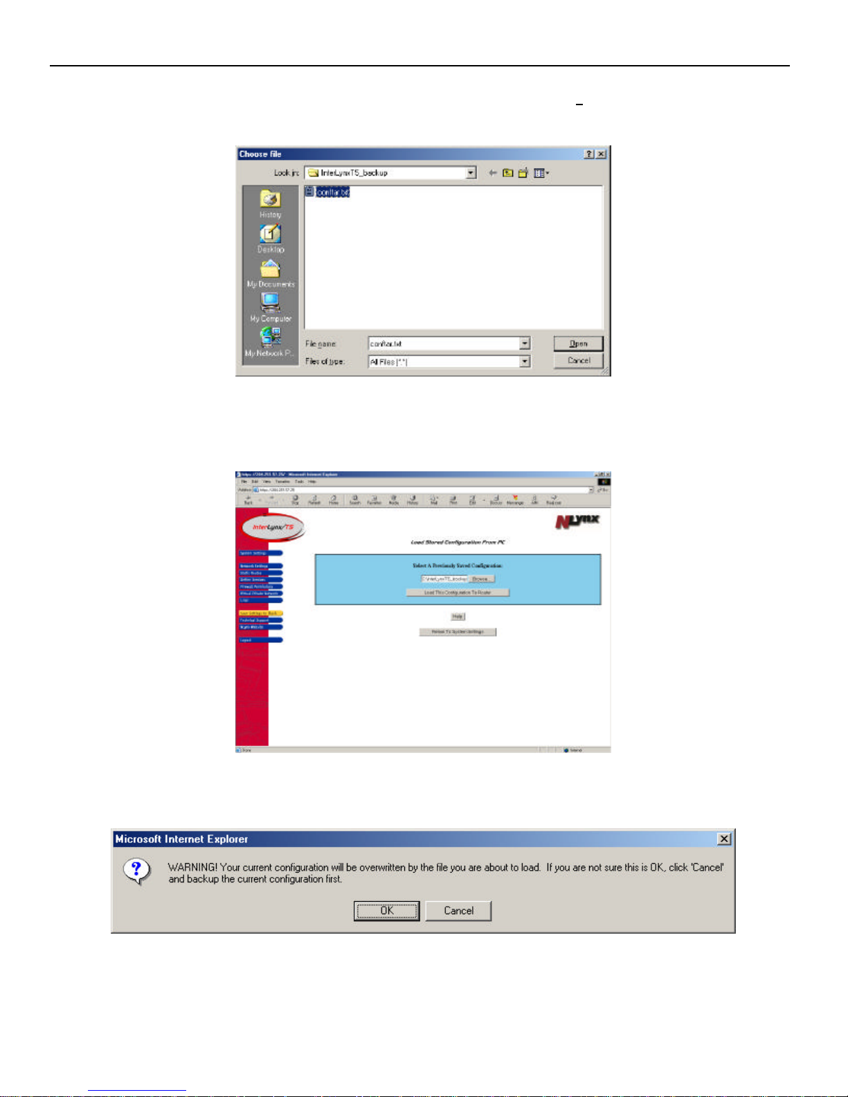
3. After pressing the Browse button, the Choose file window will appear. Locate the file that was
previously saved, highlight the file and make sure it appears in the File name text field. Press the Open
button.
4. The Load Saved Configuration From PC page will appear with the files location being displayed in
the Select A Previously Saved Configuration text field.
5. Press the Load This Configuration To Router button.
6. A Microsoft Internet Explorer dialogue box will appear with a warning about overwriting the current
configuration, choose OK to load the saved file.
3-12
Page 23
InterLynx/TS User’s Manual_________________________________________________________________
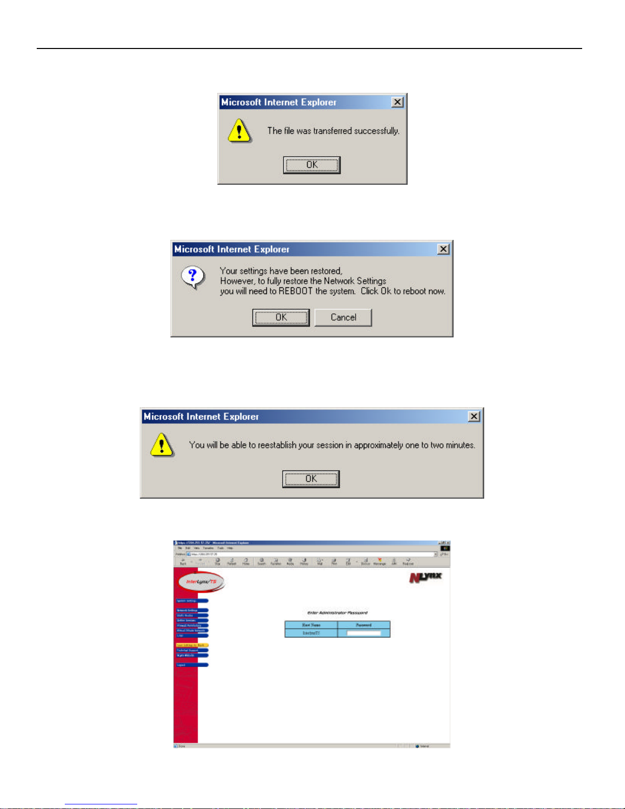
7. A Microsoft Internet Explorer dialogue box will appear indicating that the file was transferred
successfully. Press OK to continue.
8. Another Microsoft Internet Explorer dialogue box will appear explaining that the previously saved
settings have been restored and for them to take effect the system needs to be rebooted. Click OK.
9. One more Microsoft Internet Explorer dialogue box will appear explaining that a connection to the
InterLynx/TS can be established in approximately one to two minutes. Press OK to start the reboot
process. At this point the InterLynx/TS will be rebooted and the new setting will be active.
10. Click on any of the blue menu icons bring up the password prompt to log back into the InterLynx/TS.
3-13
Page 24
InterLynx/TS User’s Manual_________________________________________________________________
Part VIII – Firmware Update Via the Internet
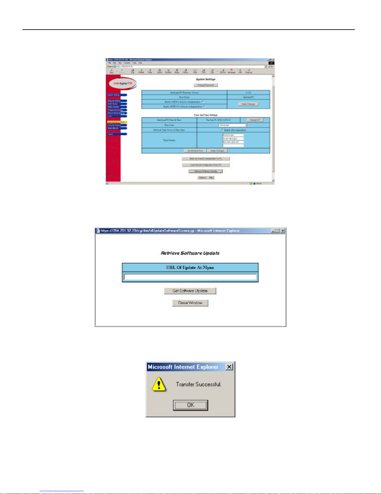
1. Click on the Retrieve Software Update button to open the Retrieve Software Update window.
2. In the Retrieve Software Update window, type the URL that Technical Support will provide for
upgrading the firmware on the InterLynx/TS. After typing in the URL, click the Get Software Update
button.
3. The previous pages will stay displayed until the firmware upgrade is successful. At this point a small
dialogue box will appear stating that the transfer was successful.
4. Press the OK button to continue.
3-14
Page 25
InterLynx/TS User’s Manual_________________________________________________________________
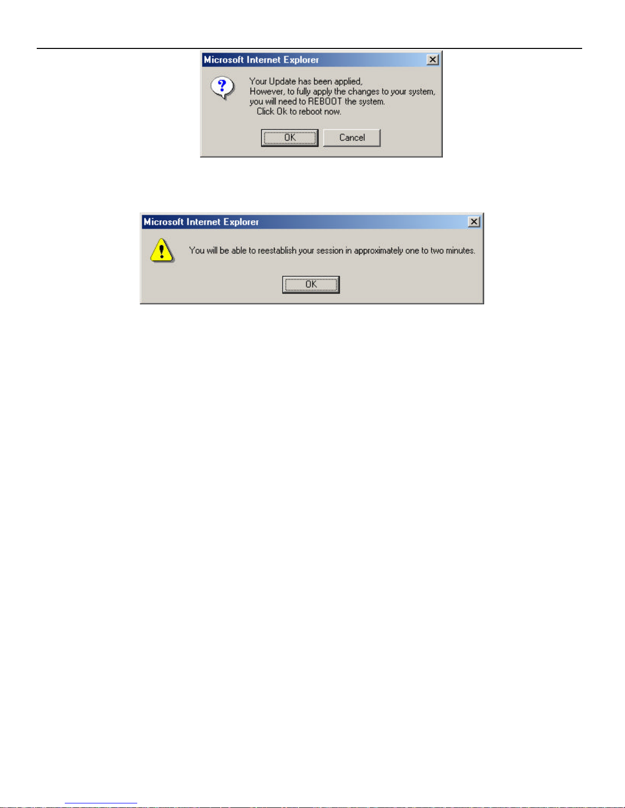
5. A Microsoft Internet Explorer dialogue box will appear, explaining that the firmware update has been
applied and that the system needs to be rebooted for changes to take affect. Press OK to continue.
6. After pressing the OK button, another dialogue box will appear indicating that communication to the
InterLynx/TS can be reestablished in 1 to 2 minutes. Press OK to reboot the InterLynx/TS.
3-15
Page 26
InterLynx/TS User’s Manual_________________________________________________________________
Chapter 4
_________________________________________________________Network Configuration
Configuring the Network interfaces on the InterLynx/TS:
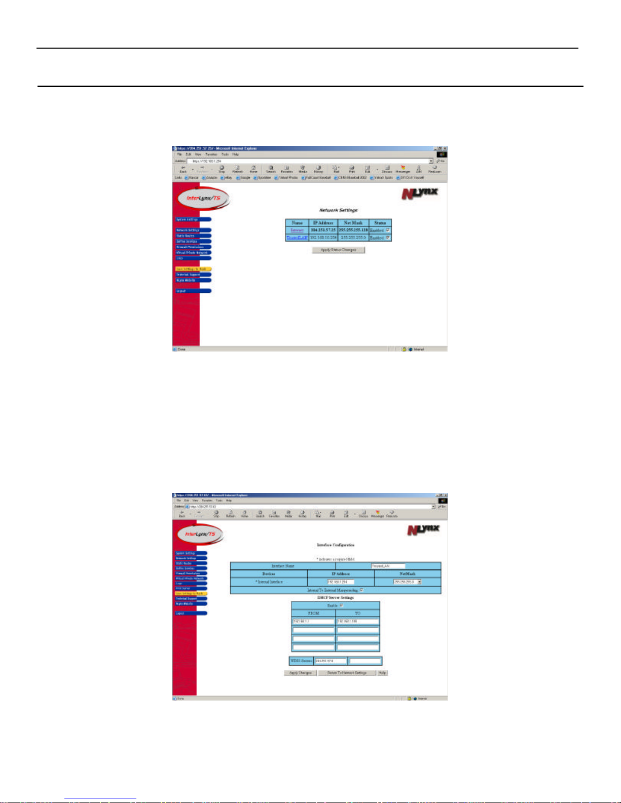
Press the ‘Network Settings’ icon located on the left hand side of the screen.
Note: The Internal (TrustedLAN) and External (Internet) interfaces can be disabled and re-
enabled if necessary by unchecking or checking the Enable box under the Status column on the
Network Settings page.
• TrustedLan (Internal):
o The InterLynx/TS internal IP address is 192.168.1.254 with a Netmask of 255.255.255.0 by
default. This can be changed to fit into an existing IP network by typing in the new IP Address
and Netmask and pressing the Apply button.
4-1
Page 27
InterLynx/TS User’s Manual_________________________________________________________________
o The InterLynx/TS will act as the DHCP Server for your internal LAN by default. The
default IP address range is 192.168.1.1 thru 192.168.1.199; the Netmask that was entered with
the TrustedLAN (Internal) IP address will be the default. These settings can be changed by
entering the new IP address ranges in the DHCP Server Settings section. The DHCP ranges
and the Internal (TrustedLAN) IP addresses must be on the same subnet. To disable the DHCP
Server settings uncheck the Enable box in the DHCP Server Settings section.
Note: If there are any changes made to the configuration, the Apply Changes button needs to be
pressed and then make sure the Save Settings to Flash button is pressed to make changes permanent.
o WINS Servers (Windows Internet Naming Service) is similar in function to a DNS Server.
Windows machines use the WINS Server to resolve NetBIOS names (Windows computer
names) to IP Addresses. Up to 2 WINS Server IP Addresses can be added to the InterLynx/TS.
The WINS Server’s IP Address will be passed out to PCs that get their IP Address from the
DHCP Server.
• Internet (External):
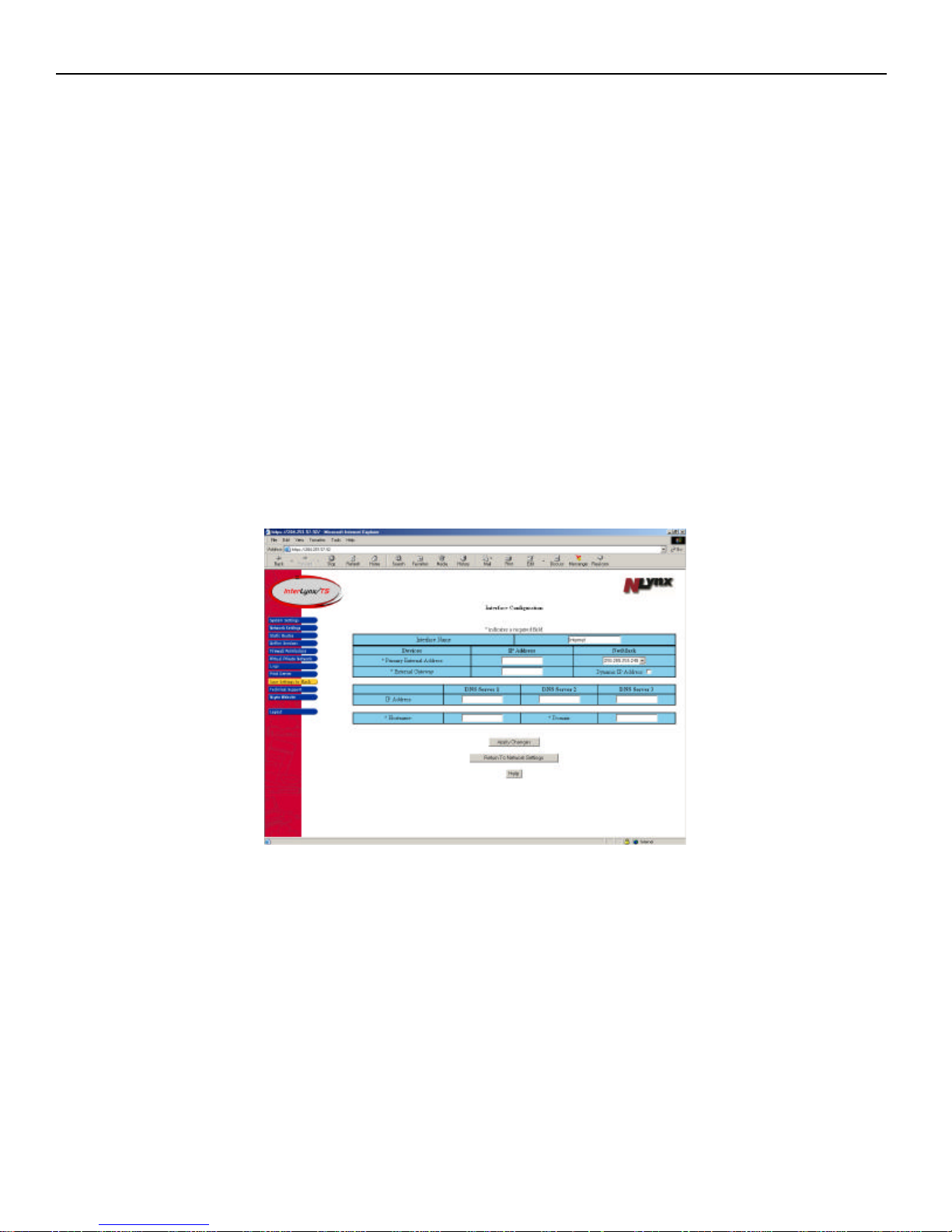
o The IP address, Netmask, and Default Gateway information that were provided by the ISP will
be entered in this section. On this page the Hostname , Domain name and DNS Server
information can be added as well. Once the information is entered, click on the Apply Changes
button, and then click the yellow Save Settings to Flash button, then reboot the unit.
• The DHCP client feature for the External Interface (Internet) is currently unavailable.
If the InterLynx/TS will be getting its’ external IP address from an ISP or other DHCP server, then
the Dynamic IP Address box must be checked for the external interface.
• DNS Server(s) can be entered into the InterLynx/TS configuration by adding the IP address of each
DNS Server under the appropriate heading on the Network Settings page, DNS Server 1, DNS
Server 2, and DNS Server 3 respectively.
• Hostname and Domain name are required. No special characters or spaces are allowed.
**NOTE: After Applying Changes, the yellow Save Setting to Flash button must be pressed in
order to make the changes permanent. This applies to changes made to either interface.
4-2
Page 28
InterLynx/TS User’s Manual_________________________________________________________________
Chapter 5
Firewall Permissions and Advanced Firewall Settings
Part I – Selecting the appropriate Firewall level to use
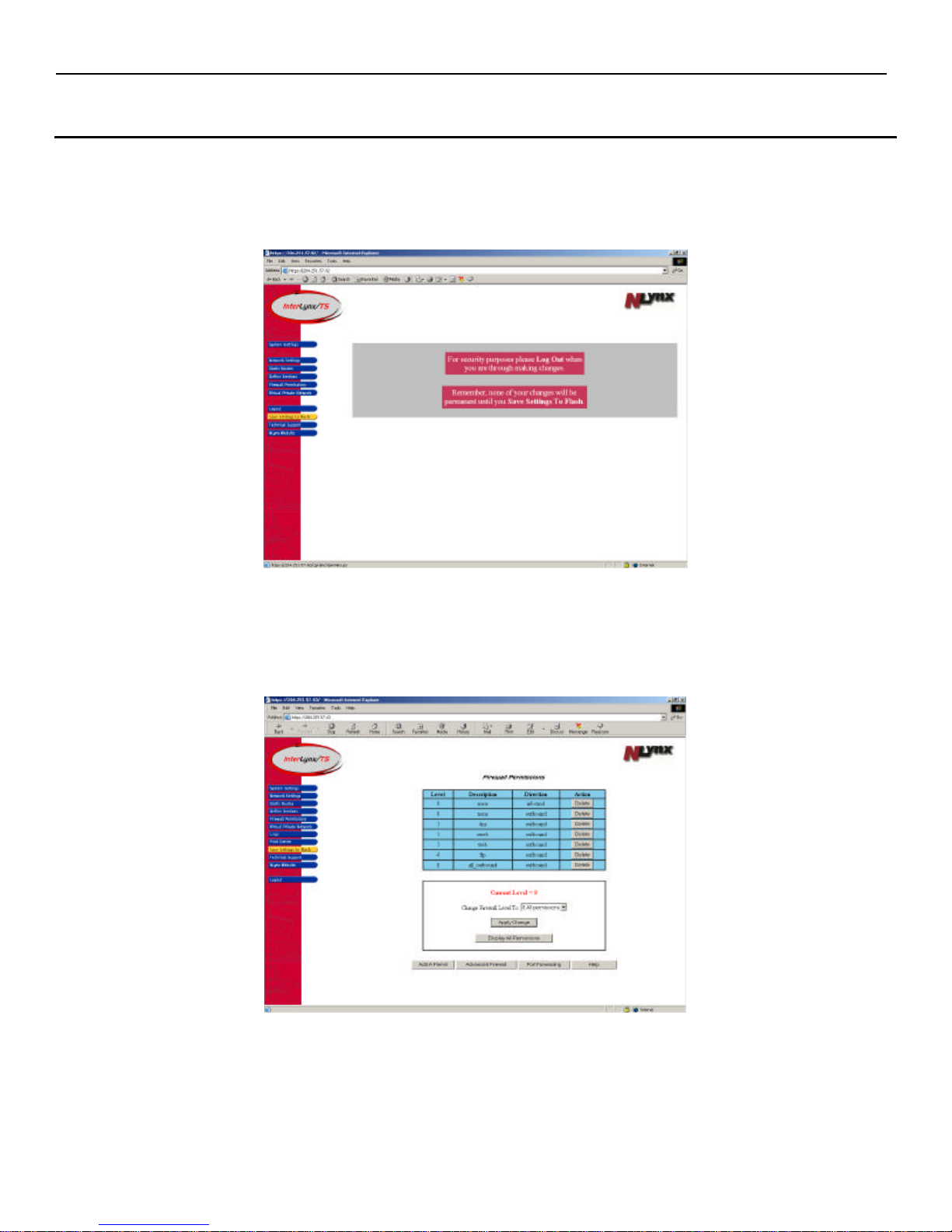
1. After logging into the InterLynx/TS, click on the Firewall Permissions button on the left hand side of
the screen. That will open the Firewall Permissions page.
2. At this point, the Firewall Permissions page will show what traffic is currently permitted through the
firewall. The default setting for the InterLynx/TS is Level 1 which allows Web, Secure Web and DNS
outbound requests and only allows inbound replies to those requests. No inbound connection requests
are accepted.
5-1
Page 29
InterLynx/TS User’s Manual_________________________________________________________________
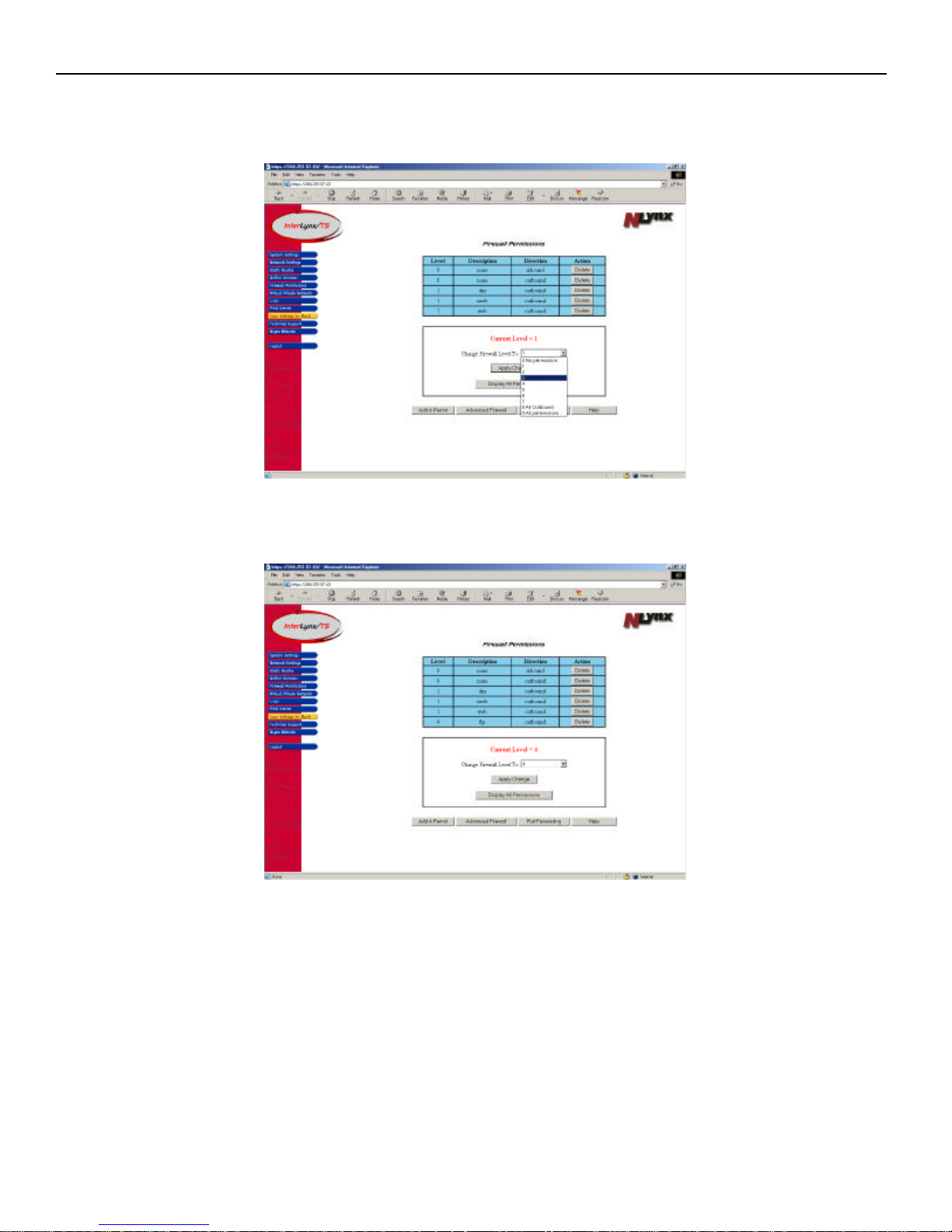
3. To change the Current Level of the InterLynx/TS, follow these steps:
a. Click on the arrow in the drop down box, and select the level of firewall to be used.
b. Click on the Apply Changes button. The screen will refresh and show the newly selected level
of the firewall.
5-2
Page 30
InterLynx/TS User’s Manual_________________________________________________________________
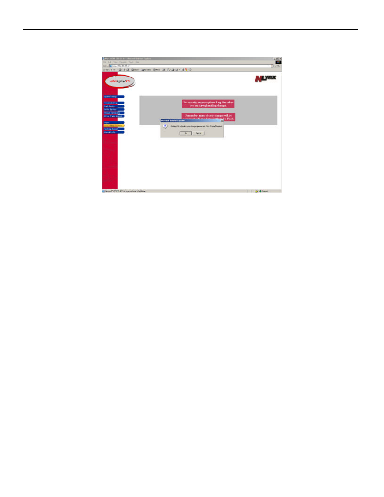
c. Now click on the yellow Save Setting to Flash button, to make the changes permanent.
d. At this point a confirmation dialogue box will appear, to confirm the choice of Save Settings to
Flash.
Note: When a Firewall Level is chosen the InterLynx/TS will allow requests by the Services, that are on that
level and all Services that are on the lower Firewall Levels. For example: If the InterLynx/TS is set to Firewall
Level 2, that means that telnet requests are allowed outbound as well as requests for the Services that are set for
Level 1, i.e.: Web, DNS and Secure Web outbound requests are allowed because those Services are on Level 1.
5-3
Page 31
InterLynx/TS User’s Manual_________________________________________________________________
Part II – Adding A New Permit to a Firewall level
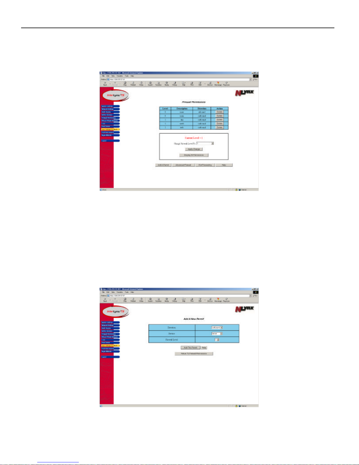
In following example, permission for Telnet outbound will be added to Firewall Level 2:
1. On the Firewall Permissions page, click the Add A Permit button.
2. At this point, the Add A Permit page will appear. Three attributes are needed in order to add a permit:
a. Direction – This can either be outbound (to the Internet) or inbound (from the Internet).
b. Service – This refers to Services that are defined on the InterLynx/TS whether they are
predefined (p) or user defined (u) Services. i.e. telnet, web, DNS, ftp etc…
c. Firewall Level – This refers to the Level at which the permit will be added. (see Note on
previous page)
3. In the Direction pull-down menu select outbound, for the Permit.
4. In the Service pull-down menu select Telnet.
5. Choose 2, in the Firewall Level pull-down menu.
6. Now click the Add This Permit button.
7. After the new Permit is added the Firewall Permissions page will be displayed.
5-4
Page 32
InterLynx/TS User’s Manual_________________________________________________________________
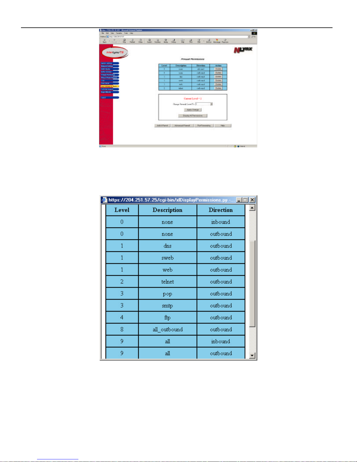
8. To see if the permit was added to the correct level, click on the Display All Permissions button. A table
of all the Permissions that have been created on the InterLynx/TS will appear in the table. All the
defined services can be viewed by scrolling thru the list. Once the Permit has been verified in the table
click the Close Table button.
9. Now click the yellow Save Settings to Flash button to save the changes and make them permanent.
5-5
Page 33
InterLynx/TS User’s Manual_________________________________________________________________
Part III – Deleting Firewall level
1. After logging into the InterLynx/TS, click on the Firewall Permissions button on the left hand side of
the screen. That will open the Firewall Permissions page.
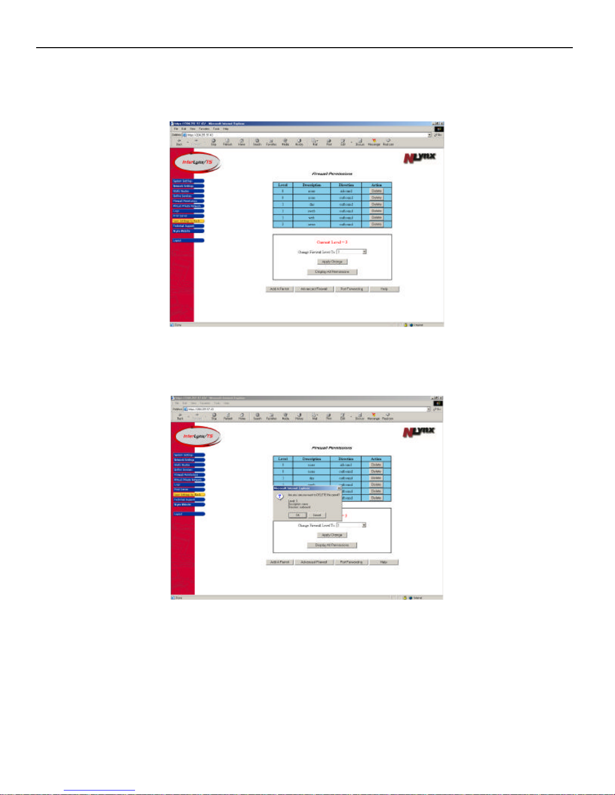
2. To remove a permit from the Firewall Permissions table, click on the Delete button in the Action
column. A confirmation box will appear, verifying the deletion of the permit. The dialogue box will
show the firewall level, description and direction of the permit. Click OK to delete the permit.
5-6
Page 34
InterLynx/TS User’s Manual_________________________________________________________________
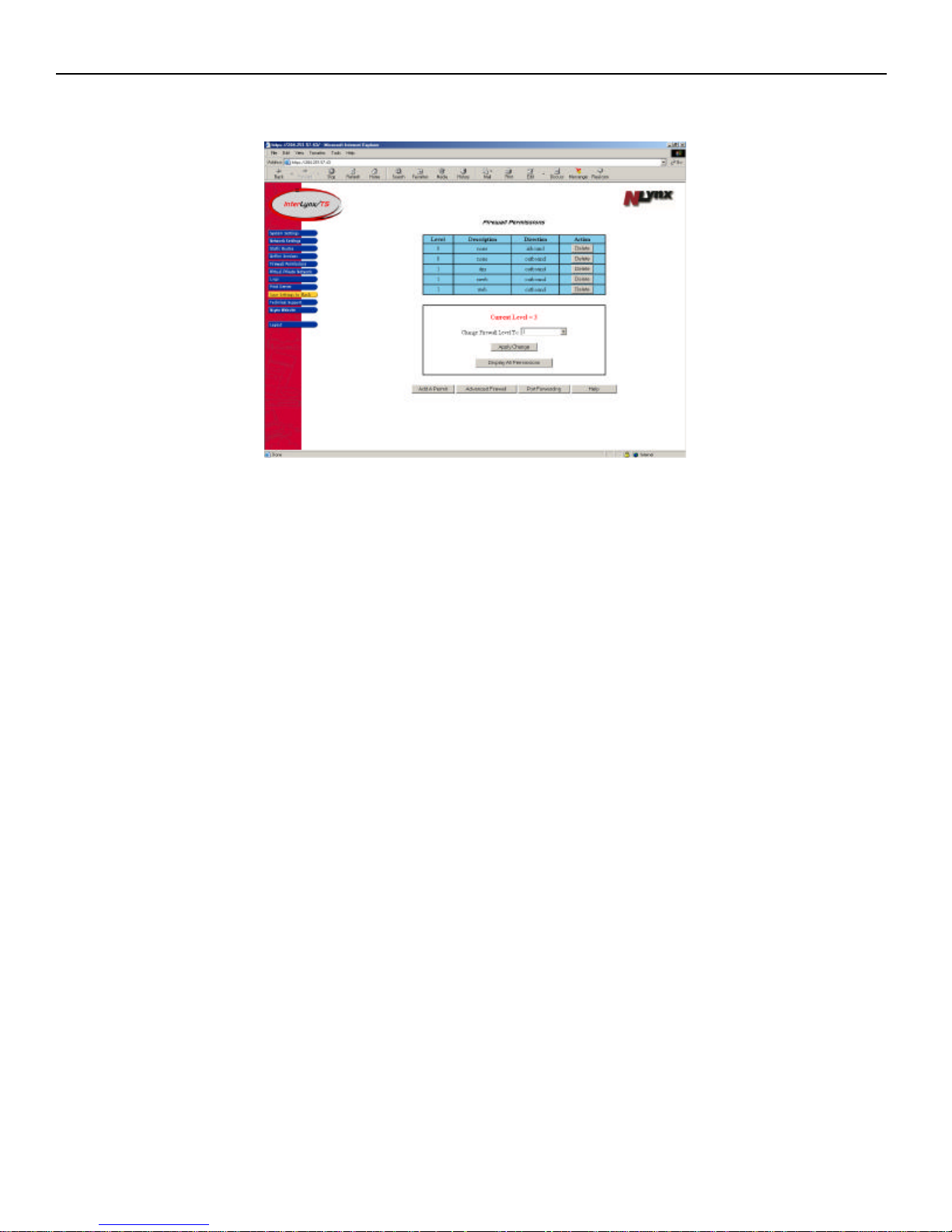
3. After deleting the permit the table will be updated showing only the permits that are configured for the
current level of the firewall or below.
4. Click the Save Settings to Flash button, to make the changes permanent.
5-7
Page 35
InterLynx/TS User’s Manual_________________________________________________________________
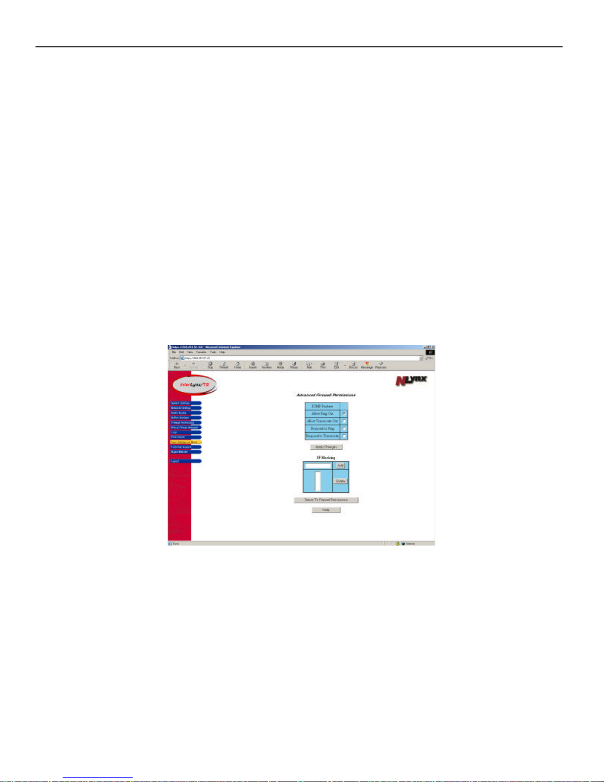
Part IV – Advanced Firewall Permissions
The Advanced Firewall Permissions page has settings that can be configured to permit the use of
Ping and Traceroute for troubleshooting purposes.
Ping and traceroute are diagnostic utilities that are helpful in isolating network connectivity and
performance problems.
Any of the following options can be enabled by checking the box to the right of each one and then pressing the
Apply Changes button.:
• Allow Ping Out: Allow clients behind the InterLynx/TS to ping machines on the Internet. This is a
relatively safe setting and may be left enabled.
• Allow Traceroute Out: Allow clients behind the InterLynx/TS to trace the route to machines on
the Internet. This is a relatively safe setting and may be left enabled.
• Respond to Ping: Allow the InterLynx/TS to respond to ping requests from machines on the
Internet. This should be enabled for debugging only.
• Respond to Traceroute: Allow the InterLynx/TS to respond to traceroute requests from machines
on the Internet. This should be enabled for debugging only.
5-8
Page 36
InterLynx/TS User’s Manual_________________________________________________________________
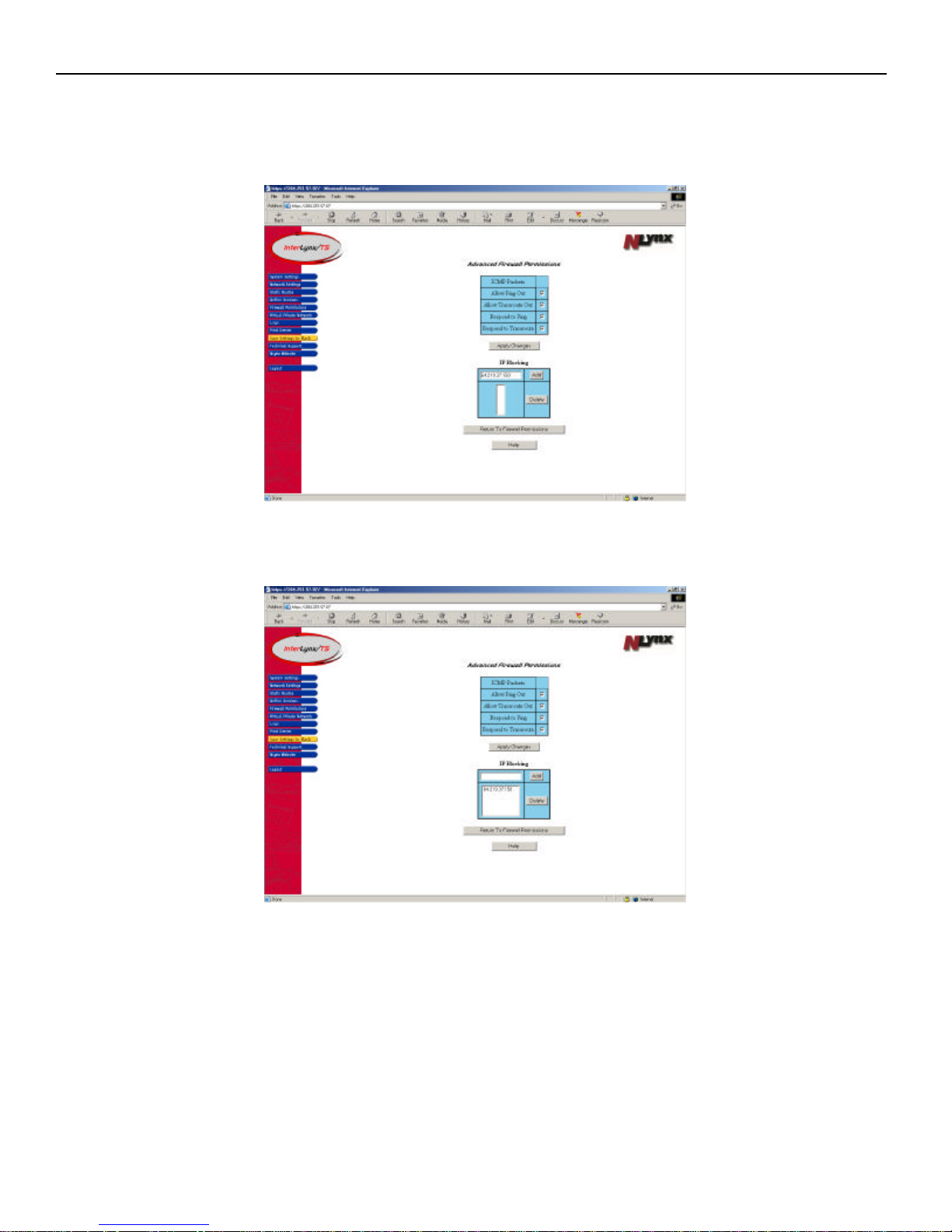
• IP Blocking: You can provide a list of IP addresses or URLs that are to be blocked by the
InterLynx/TS.
o Enter the URL to be blocked in the text box and press the Add button.
o After pressing the Add button the screen will refresh with the newly added URL in the blocked
area.
5-9
Page 37
InterLynx/TS User’s Manual_________________________________________________________________
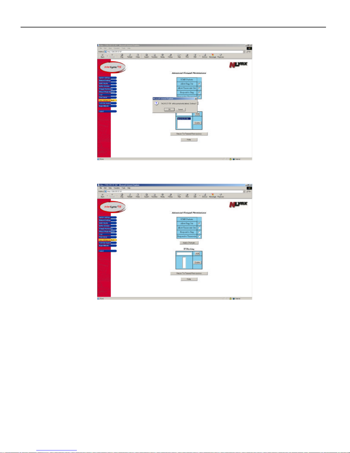
o To remove any of the URLs, highlight the URL and then press the Delete button
o A Microsoft dialogue box will appear verifying the deletion of the URL. Click OK.
o The screen will refresh and the URL will no longer be in the list of blocked URLs.
Click the Save Settings to Flash button, to make the changes permanent.
5-10
Page 38
InterLynx/TS User’s Manual_________________________________________________________________
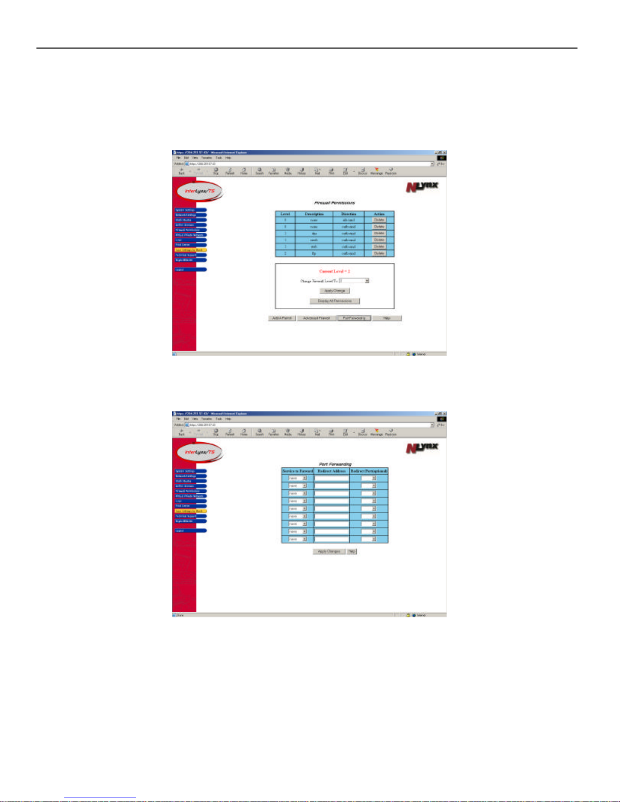
Part V – Port Forwarding
This function allows devices outside the internal LAN to communicate with internal devices by redirecting the
Services created on the InterLynx/TS.
1. After logging into the InterLynx/TS, click on the Firewall Permissions button in the left side menu.
2. When the Firewall Permissions page is shown, click on Port Forwarding button to open the Port
Forwarding Page.
• The following two examples will show how to do Standard Port Forwarding and Port Forwarding
using Alternate Port numbers.
5-11
Page 39
InterLynx/TS User’s Manual_________________________________________________________________
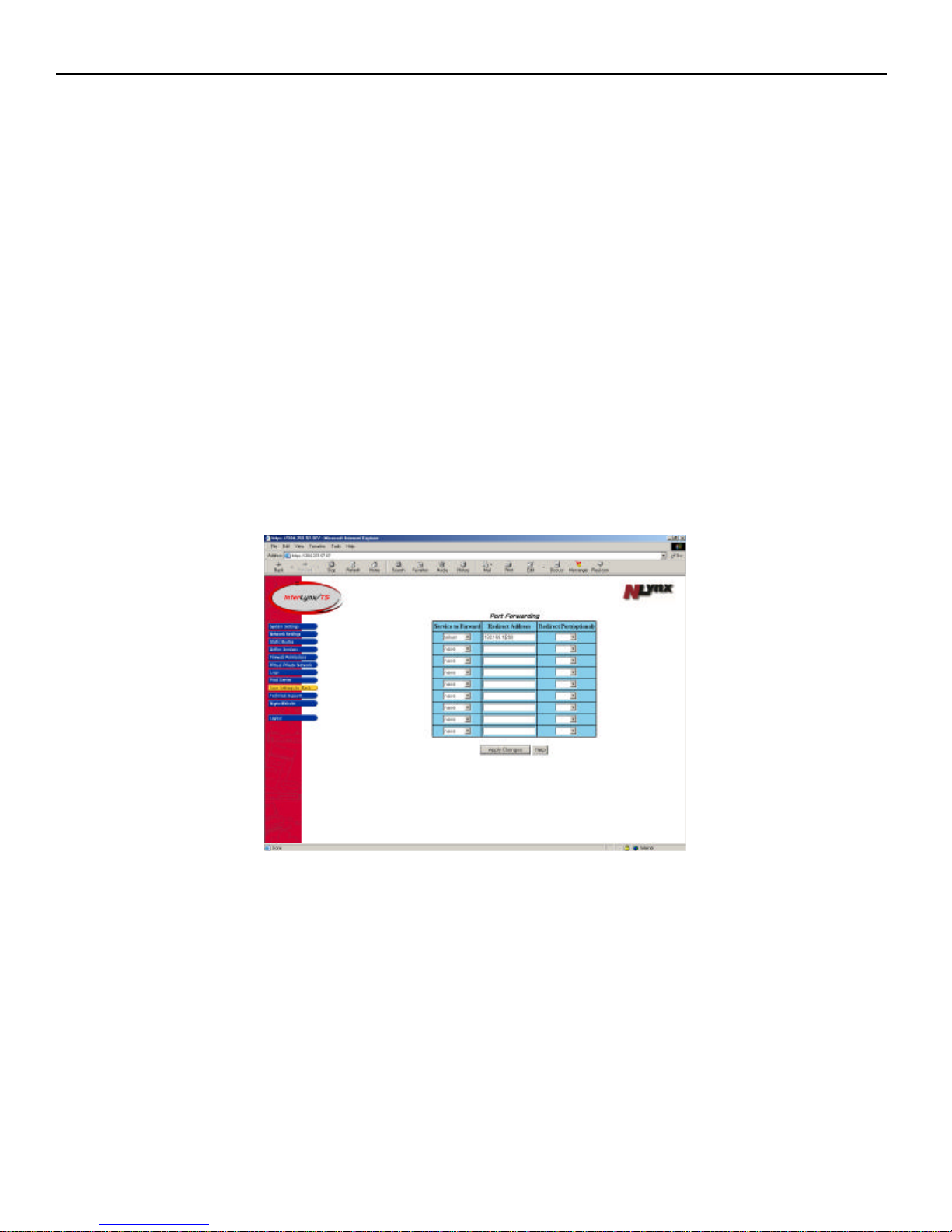
Standard Port Forwarding
The Port Forward page consists of a 3 column table. The table headings and explanations are as follows:
• Service to Forward - is the service that will be forwarded. It was created in the Define Services page,
and it contains a name, description, protocol and one or more ports that are associated with the protocol.
• Redirect Address - is the address on the Trusted LAN that the service will be forwarded to.
• Redirect Service - will define the service as well as the port number for the forwarded service. Note: If
this field is left blank, the InterLynx/TS will use the same service that is selected in the Service to
Forward field.
When using Standard Port Forwarding, the protocols will use the port numbers that are defined in RFC 1700.
1. For example, if the Service to Forward is telnet, (the predefined service named telnet on the
InterLynx/TS, uses the protocol tcp with port number 23) then select telnet in the Service to Forward
field.
2. In the Redirect Address field type the IP Address of the device on the Trusted LAN that the service
will be redirected to.
3. The Redirect Service (optional) should be left blank, if the service being redirected is the same as the
Service to Forward. Leaving this field blank will use the same service that is chosen in the Service to
Forward field.
4. Press the Apply Changes button when done adding Services to be forwarded.
5. To remove a service from the list choose none under Service to Forward, delete the IP Address and
select the blank option under Redirect Service(optional) and then press Apply Changes.
Be certain to Save Settings to Flash if you want them to be permanent.
5-12
Page 40
InterLynx/TS User’s Manual_________________________________________________________________
Alternate Port Forwarding
The Port Forward page consists of a 3 column table. The table headings and explanations are as follows:
• Service to Forward - is the service that will be forwarded. It was created in the Define Services page,
and it contains a name, description, protocol and one or more ports that are associated with the protocol.
• Redirect Address - is the address on the Trusted LAN that the service will be forwarded to.
• Redirect Service - will define the service as well as the port number for the forwarded service. Note: If
this field is left blank, the InterLynx/TS will use the same service that is selected in the Service to
Forward field.
The services can be created with port numbers that are not the normal RFC port number for security
reasons, and then have the services redirected internally using the correct port numbers.
The following example will show how to create a telnet service using an alternate port number for security
reasons.
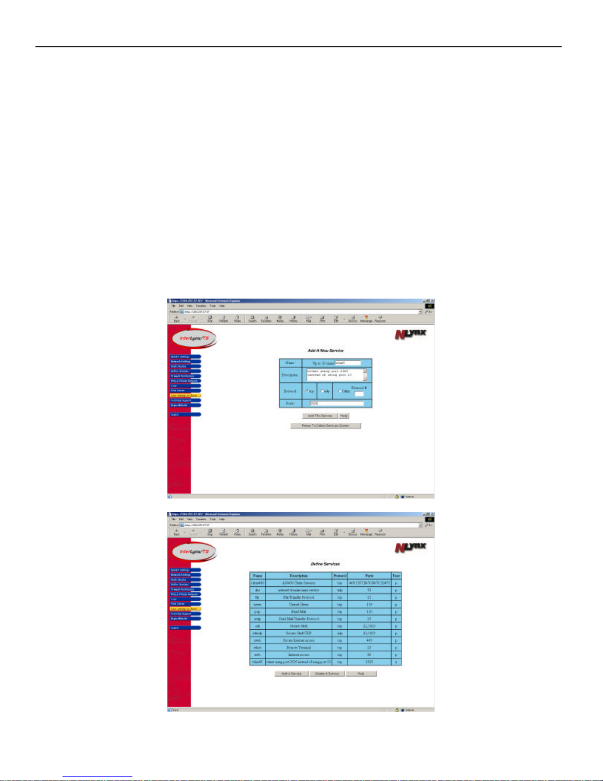
1. The first step will be to create the new service in the Define Services page. The new service name will
be telnetX and will use port #2525. Go to the Define Services page to create the new service.
5-13
Page 41
InterLynx/TS User’s Manual_________________________________________________________________
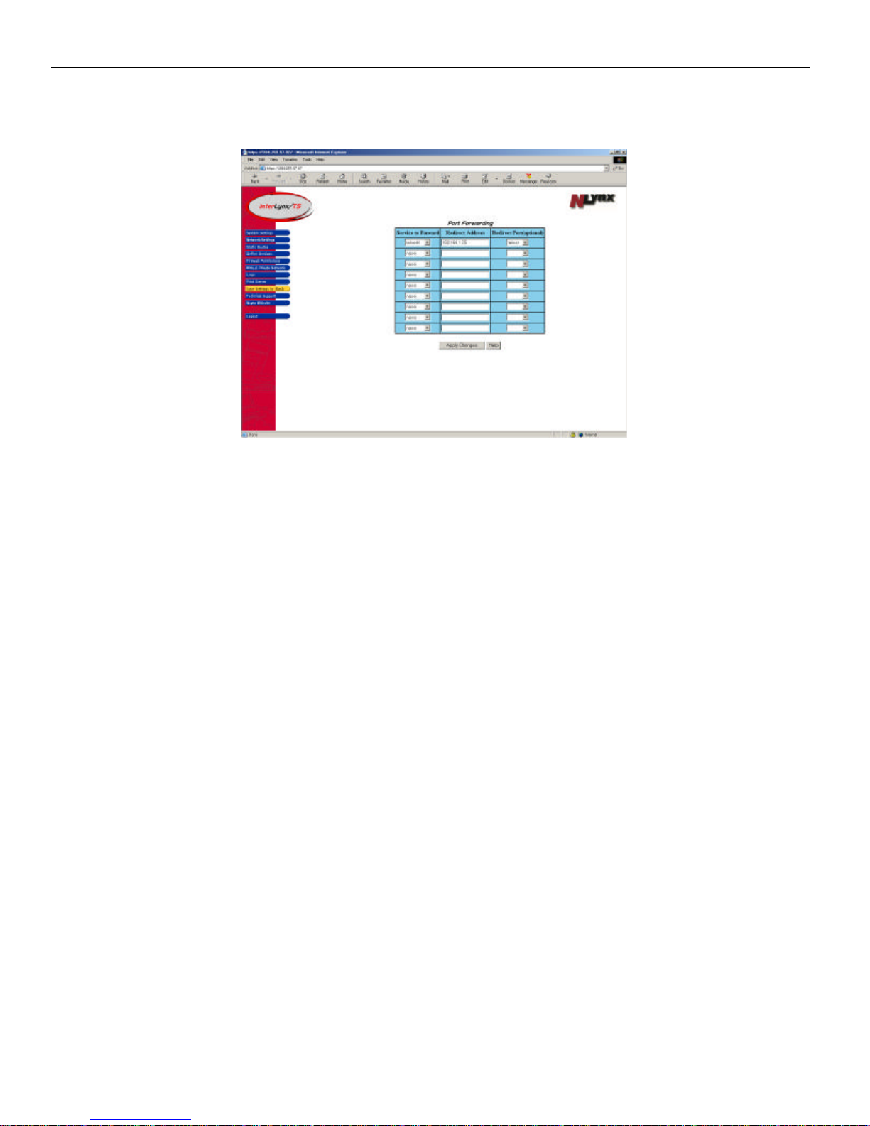
2. After the new service has been created and verified, return to the Advanced Firewall, Port Forward
page.
3. In the Port Forward page the new service will be used to define the new forwarding rule.
4. The new Service to Forward is telnetx, (created in the Define Services page) select telnetx in the
Service to Forward field.
5. In the Redirect Address field type the IP Address of the device on the Trusted LAN that the service
will be redirected to.
6. The Redirect Service (optional) should be telnet. The reason for this is the device on the internal
network is expecting to receive the telnet packet coming in on port 23. The service telnet is defined
with tcp using port 23. This field should not be left blank, unless the receiving device is configured to
accept the packet with the alternate port.
7. Press the Apply Changes button when done adding Services to be forwarded.
8. To remove a service from the list choose none under Service to Forward, delete the IP Address and
select the blank option under Redirect Service(optional) and then press Apply Changes.
Be certain to Save Settings to Flash if you want them to be permanent.
5-14
Page 42
InterLynx/TS User’s Manual_________________________________________________________________
Chapter 6
Adding and Deleting Firewall Services on the InterLynx/TS
Part I – Adding a new Service
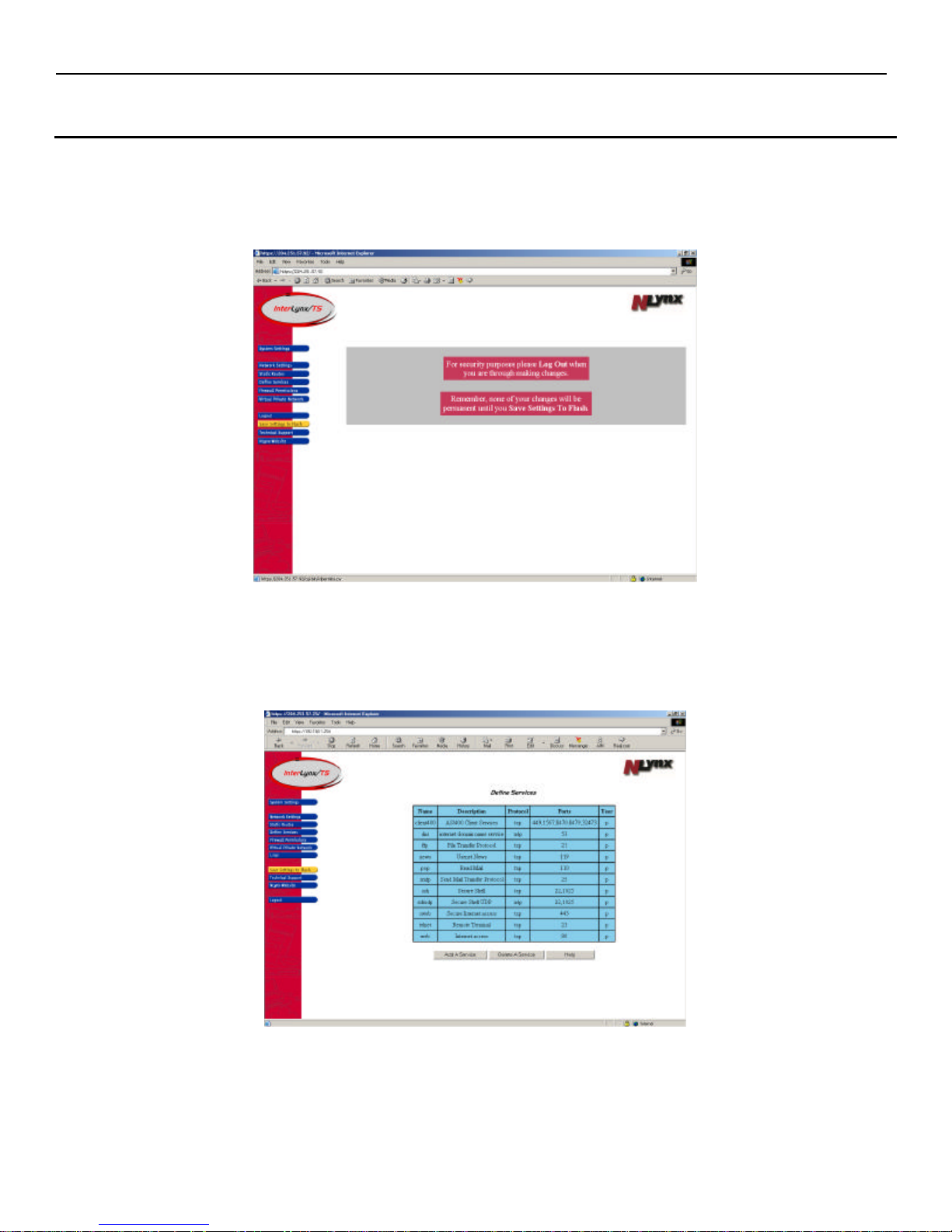
a. After logging into the InterLynx/TS, click on the Define Services button on the left hand side of the
screen. That will open the Define Services page.
b. When the Define Services page appears, there will be a table listing all the currently defined Services on
the InterLynx/TS. There are two types of Services: predefined and user-defined. Predefined Services
are indicated, by the letter p in the Type column and the User-defined Services are marked with a u in
the Type column. Click on the Add A Service button to add a new Service.
6-1
Page 43
InterLynx/TS User’s Manual_________________________________________________________________
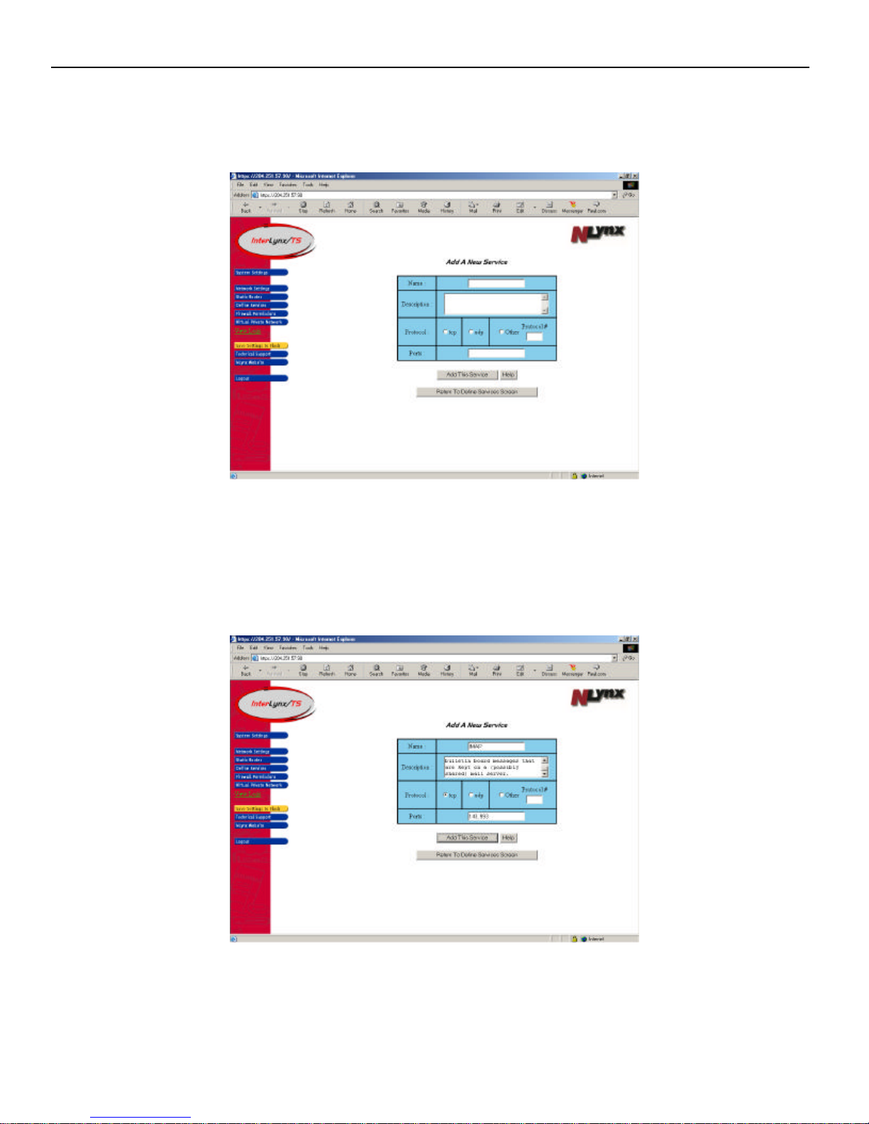
NOTE: The following two examples will show how to:
• Add a Service that uses a Port specific Protocol (IMAP)
• Add a Service that uses a numbered Protocol (GRE).
c. Adding a new Service (IMAP).
a. In the Name field type IMAP.
b. In the Description field enter: Internet Message Access Protocol. It is a method of accessing
electronic mail or bulletin board messages that are kept on a (possibly shared) mail server.
c. Check the tcp radio button in the Protocol field.
d. In the Port(s) type in the required port numbers 143 and 993. Separate the two numbers with a
comma.
e. Click on the Add This Service button, to add the new Service to the InterLynx/TS.
6-2
Page 44
InterLynx/TS User’s Manual_________________________________________________________________
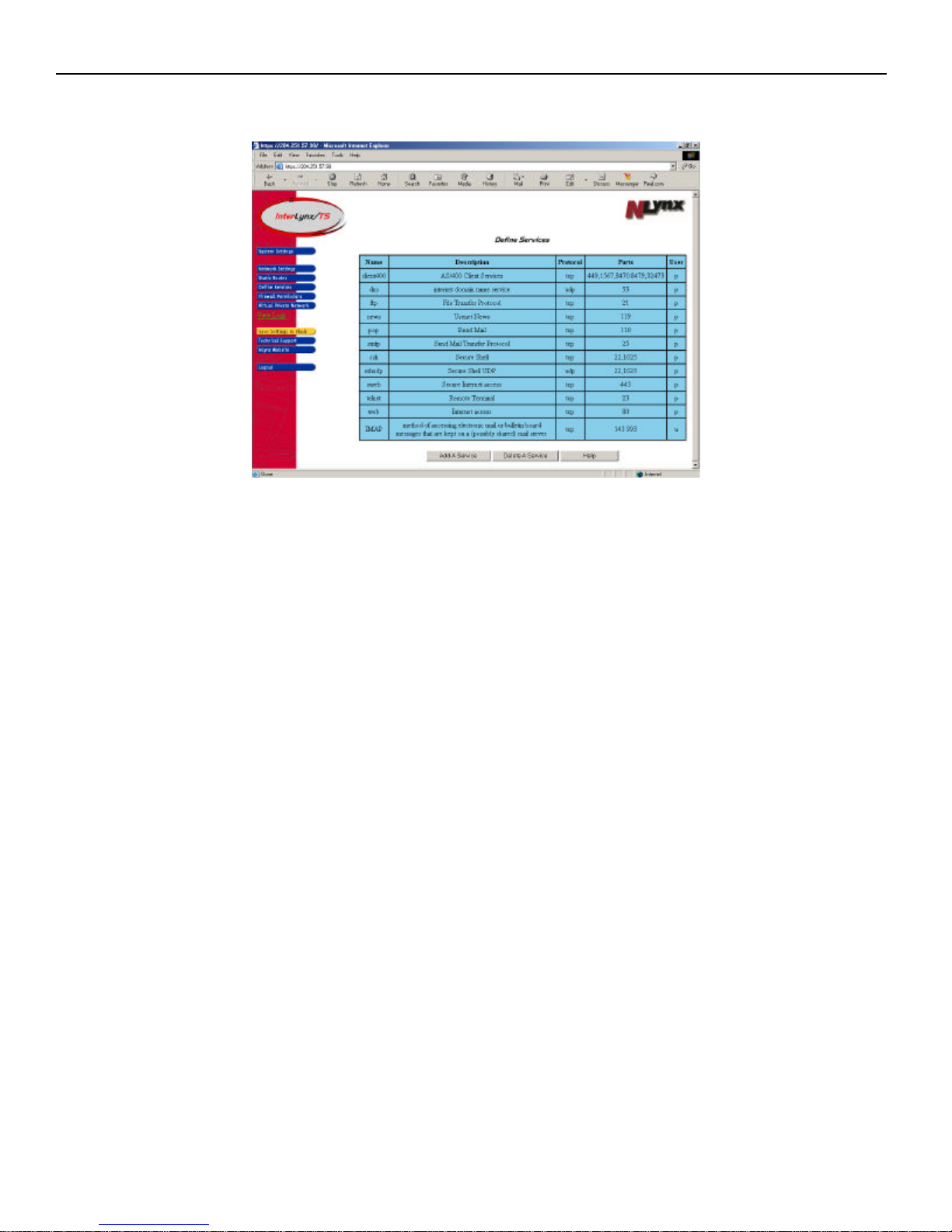
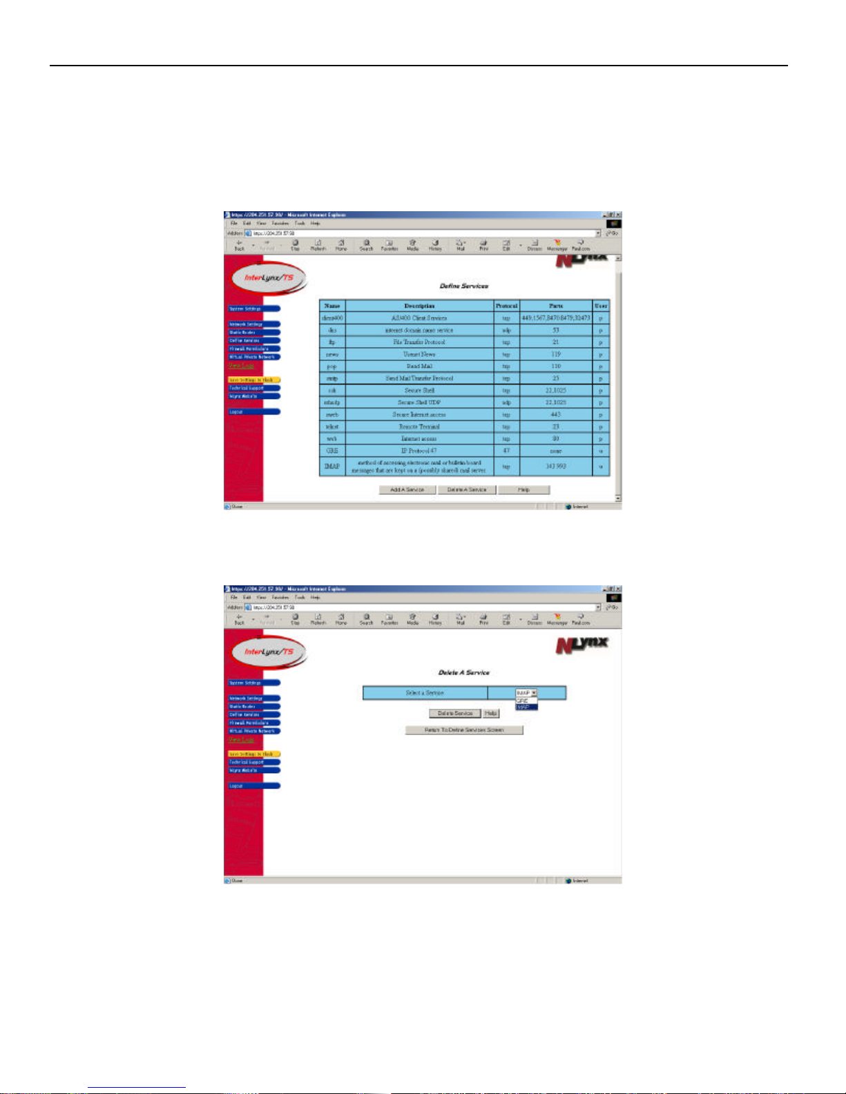
f. After pressing the Add This Service button, the updated Define Services page will appear with
the latest Services appearing in the bottom of the table.
g. Now click on the yellow Save Setting to Flash button, to make the changes permanent.
6-3
Page 45
InterLynx/TS User’s Manual_________________________________________________________________
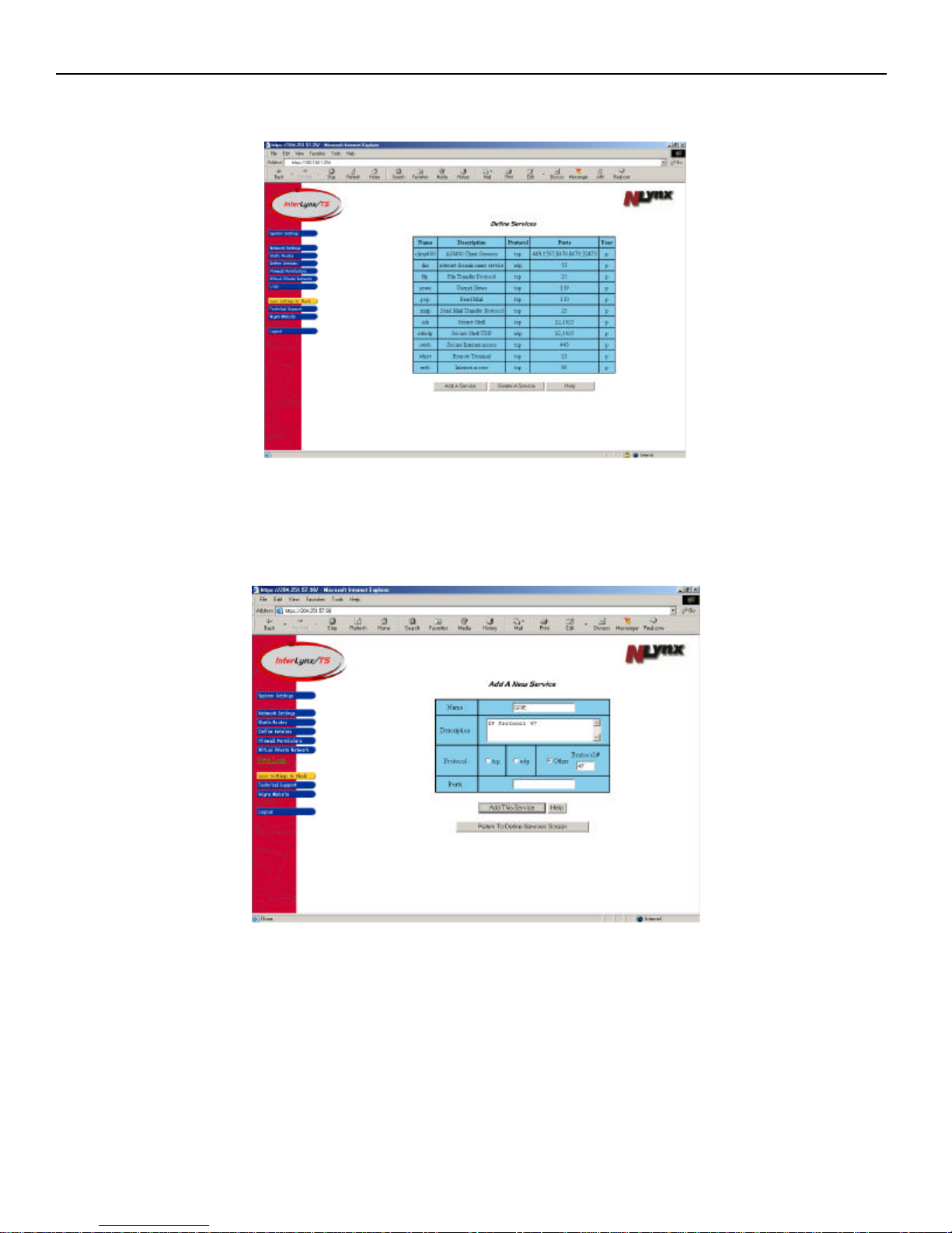
4. Adding a new Service (GRE).
a. Click on the Add A Service button to add a new Service.
b. In the Name field type GRE.
c. In the Description field enter: IP Protocol 47
d. Check the other radio button in the Protocol field and type 47 in the Protocol # box.
e. Since GRE is not Port specific, nothing is entered in the Ports entry field.
6-4
Page 46
InterLynx/TS User’s Manual_________________________________________________________________
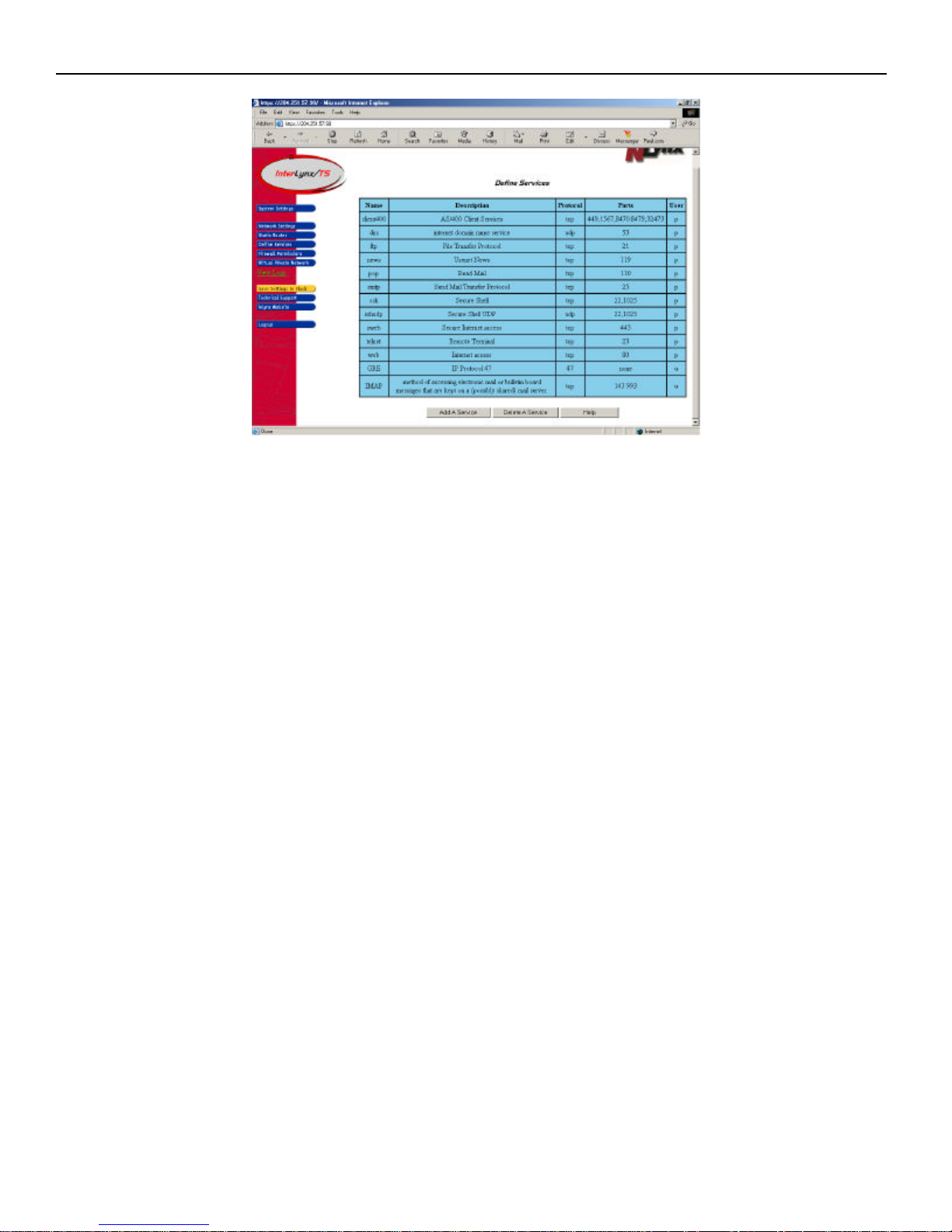
f. Click on the Add This Service button, to add the new Service to the InterLynx/TS.
h. After pressing the Add This Service button, the updated Define Services page will appear with
the latest Services appearing in the bottom of the table.
i. Now click on the yellow Save Setting to Flash button, to make the changes permanent.
6-5
Page 47
InterLynx/TS User’s Manual_________________________________________________________________
Part II – Deleting A Defined Service
**NOTE: A Predefined Service (p) cannot be deleted from the Define Services table.
1. Click on the Define Services button on the left side of the screen, this will open the Define Services
page. Now click on the Delete A Service button.
2. At this point the Delete A Service page is now visible.
3. Select a Service to delete by using the pull-down menu of user configured Services.
6-6
Page 48
InterLynx/TS User’s Manual_________________________________________________________________
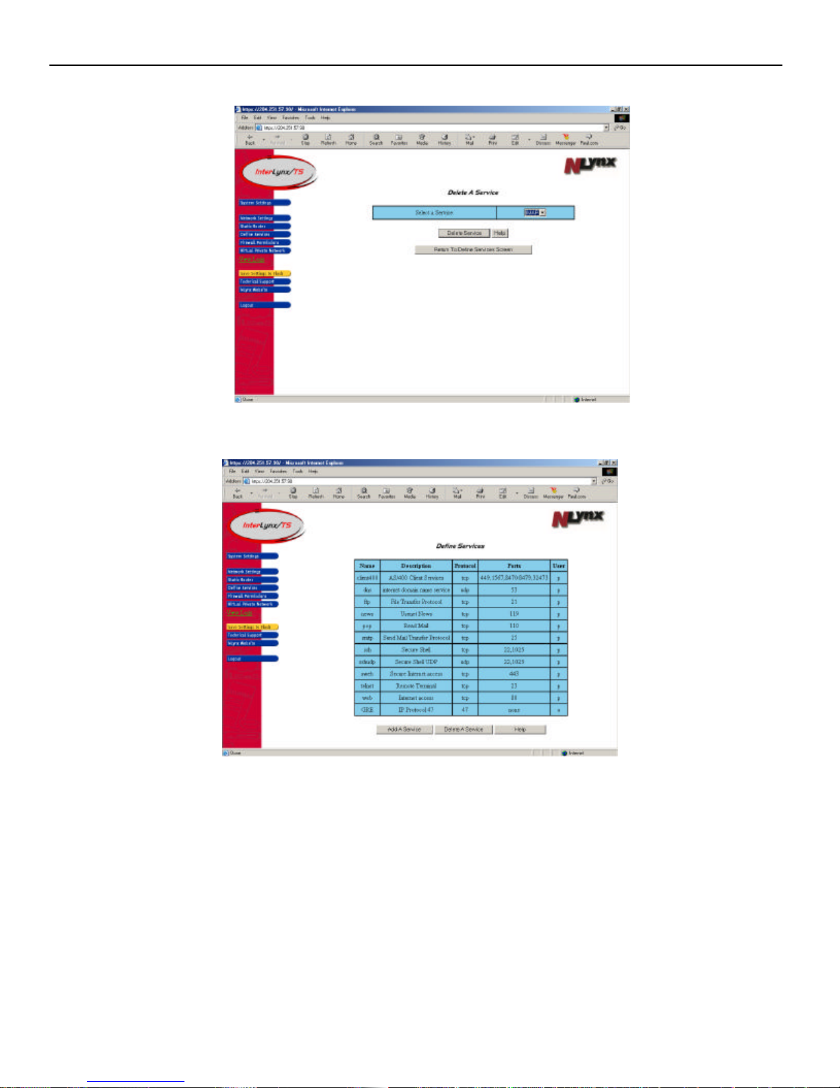
d. Once the Service to be deleted is selected, press the Delete Service button.
e. The updated Define Services table will appear with the remaining Services for the InterLynx/TS listed in
the table.
f. Now click on the yellow Save Setting to Flash button, to make the changes permanent.
6-7
Page 49
InterLynx/TS User’s Manual_________________________________________________________________
Router A
192.168.5.1/24
192.168.1.254/24
192.168.1.154/24
Chapter 7
_________________________________________________________________Static Routes
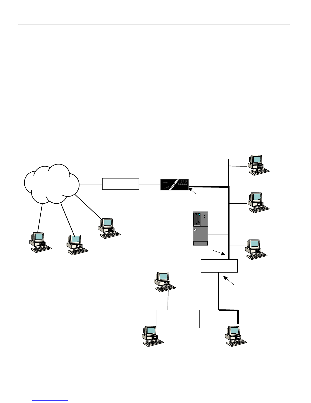
Static routes are required when the InterLynx/TS must communicate via its internal network interface with
devices connected to a network segment located on the far side of a router. In the example below the
InterLynx/TS needs to have a static route to the 192.168.2.0/24 network through router B. A static route
consists of two things:
1) A destination (set of IP addresses to which it applies) – expressed as an IP address and
netmask.
2) A route via, or next hop, which is the IP address of the router. This must be on the same subnet as the
InterLynx/TS.
In the example below, a static route will need to be added to the InterLynx/TS. The steps will be shown
following the example.
192.168.1.0/24
Internet
PC
InterLynx/TS
PC
Email server
AS/400
Router B
Server
7-1
192.168.5.0/24
PC
PC
Page 50
InterLynx/TS User’s Manual_________________________________________________________________
Adding a Static route
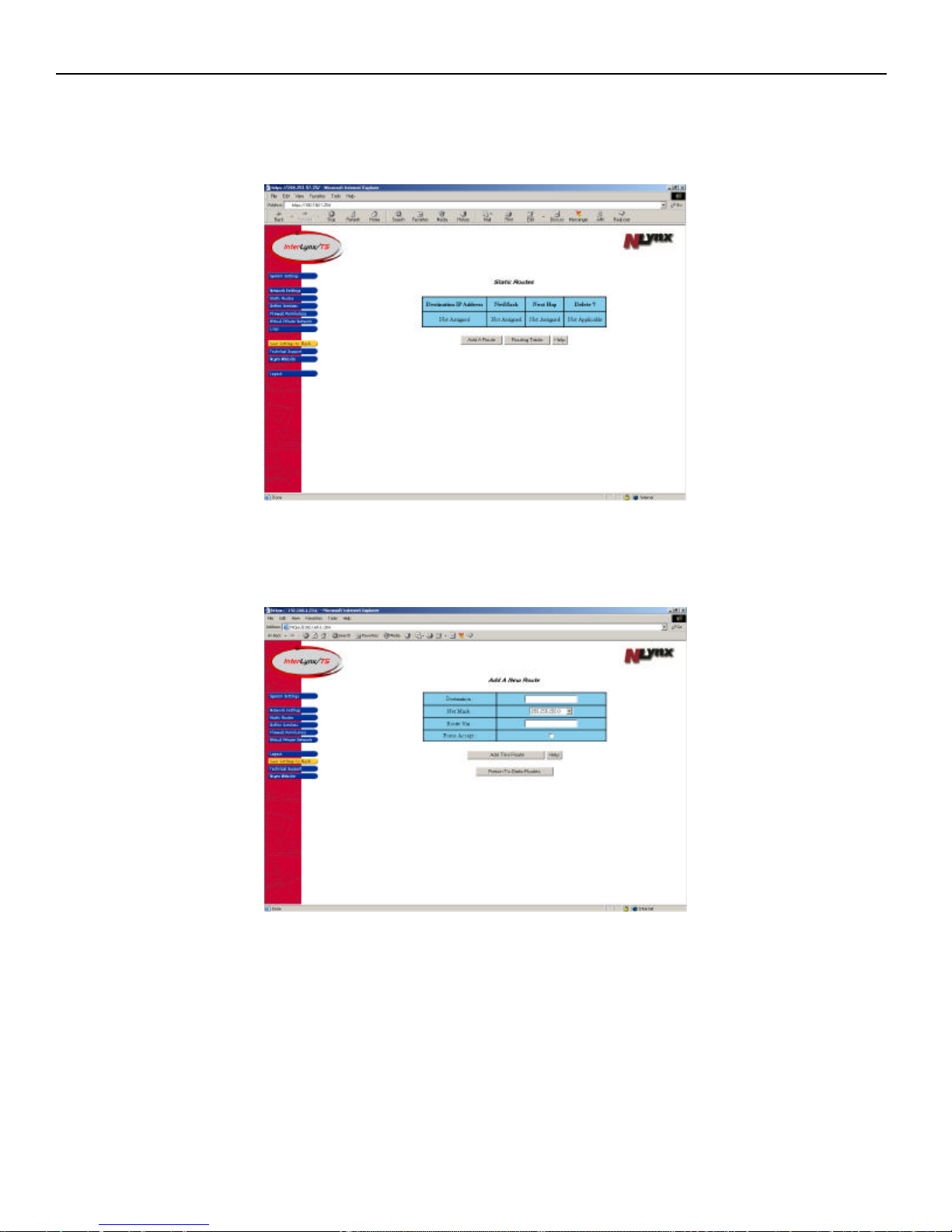
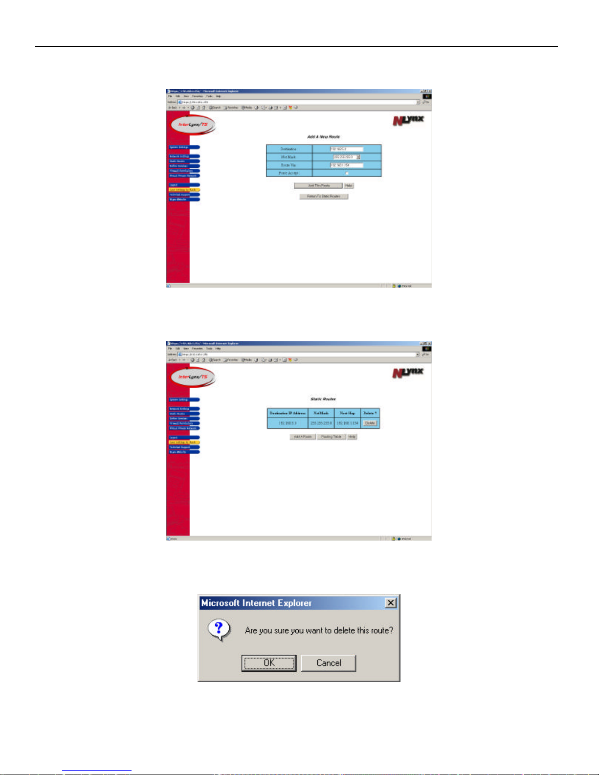
1. Click on the Static Routes icon on the tool bar on the left side of the screen. This will bring up the Static
routes page.
2. Next step is to click on the Add A Route button.
3. In this window the Destination networks’ IP address is added as well as the subnet mask for the
network. Then add the Route Via (next hop) IP address, this address must be on the same subnet as the
InterLynx/TS.
7-2
Page 51
InterLynx/TS User’s Manual_________________________________________________________________
4. Once the parameters have been entered for the Static route, click on the Add This Route button. See
example below:
5. After the Add this Route button is pushed the route will be added to the Static Routes table as shown
below.
6. To delete a route click on the Delete under the Delete Column. Click yes on the dialogue box that pops
up. Click on the yellow Save Settings to Flash icon to make the changes permanent.
7. For a complete list of routes associated with the InterLynx/TS, press the ‘Routing Table’ button.
7-3
Page 52
InterLynx/TS User’s Manual_________________________________________________________________
Chapter 8
___________________InterLynx/TS-to-InterLynx/TS VPN Configuration Using RSA Key
NOTE: The recommended Security authentication method is RSA key. RSA key provides greater
security over Shared Secret in the fact that RSA key uses a Public and a Private key pair, where as with
Shared Secret the VPN devices share the same authentication key.
Part I - VPN Configuration Instructions for Using RSA Key:
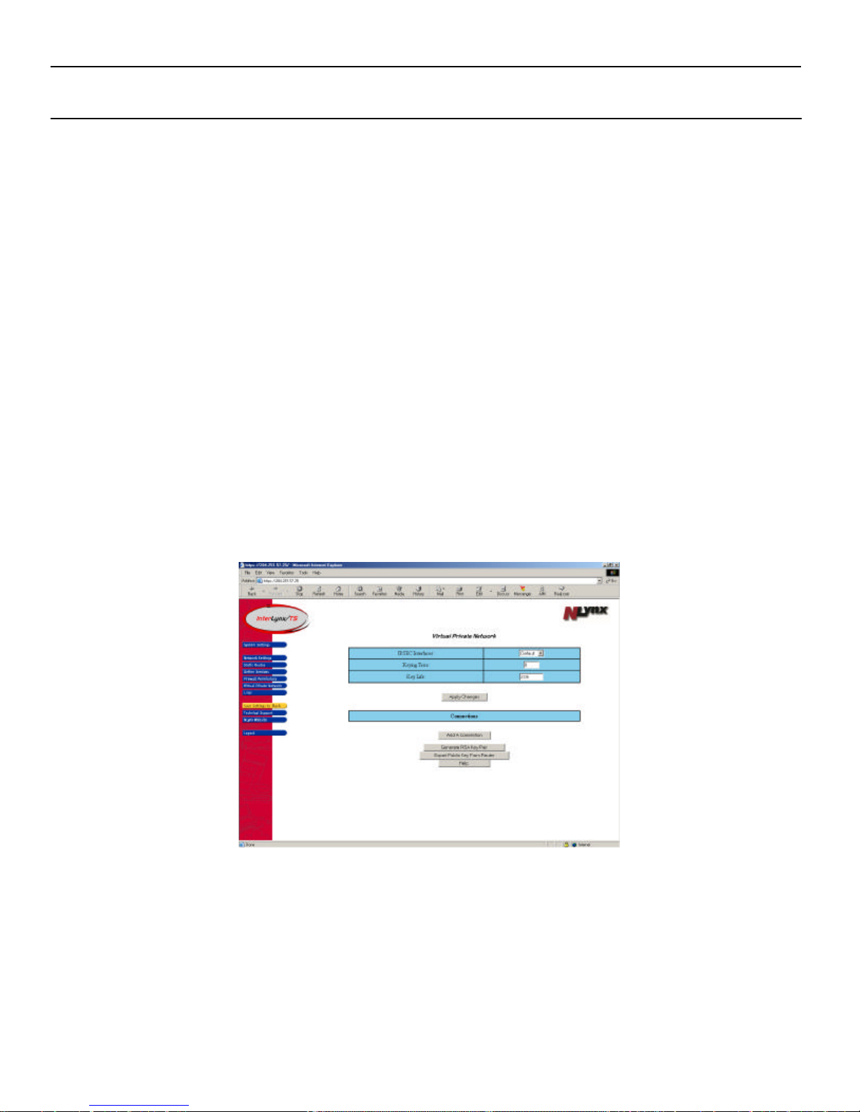
1. Click on the Virtual Private Network button on the left side of the screen. This will bring up the
Virtual Private Network page.
2. On the Virtual Private Network page, there are three settings that pertain to all VPN connections
configured on this InterLynx/TS:
a. IPSEC Interfaces:
• Default – This setting uses the default route in the routing table to determine
which External interface should be used for the VPN.
• Ethernet – Choose this setting to force the VPN to use the Ethernet interface.
• Dialup – Select this setting to force the VPN to use the Dialup interface.
b. Keying Tries – This is the number of times the units will negotiate the VPN or attempt to re-key
after the key has expired. Note: 0 equals continuous retries.
c. Key Life – The time in hours from successful negotiation to the key expiration. The value must
be entered in this format 3.0h (h stands for hours). The default is 2.0h.
8-1
Page 53
InterLynx/TS User’s Manual_________________________________________________________________
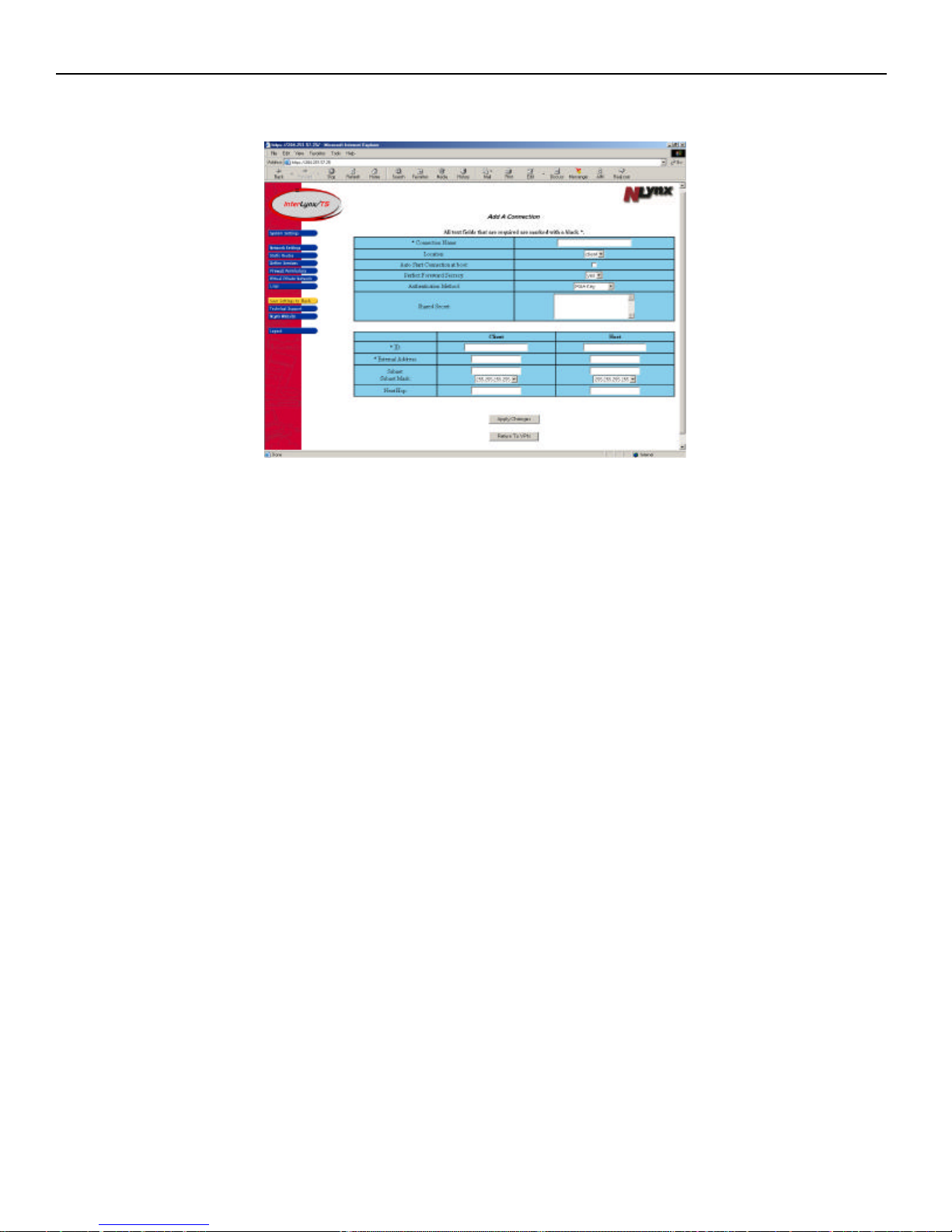
3. Click on the Add A Connection button. This will open the Add A Connection page to begin the VPN
configuration process.
4. In the Add A Connection page the following information is required to setup the VPN:
a. Connection Name This will be the name of the VPN. i.e. Austin2UK.
b. Location There are two choices here, Host side (corporate network) and Client side (remote
site or device).
c. Auto Start Connection at Boot When this box is checked, the unit will automatically try to
bring up the VPN connection when the unit is rebooted. (We recommend that the Client side
box be checked and the Host site box remains unchecked.)
d. Perfect Forward Secrecy The use of a short term key and a long term key, so that if one key is
compromised the data is still secure. If both keys are compromised only the data associated with
that set of keys is vulnerable until the next re-keying sequence. Default is yes ( recommended)
e. Authentication Method There are two choices for authentication, RSA Key and Shared
Secret. Choose RSA Key. RSA Key uses key pairs that are generated and exchanged between
VPN devices.
f. Shared Secret This area is not used when using RSA Key. This is where the ”secret pass
phrase” that will be shared by the VPN devices is entered.
g. ID This should be the same IP address that is entered for the External Address.
h. External Address This is the IP address associated with the external interface(the interface
connected to the router/internet) of each device.
i. Subnet This is the IP address range (the IL/TS default is 192.168.1.0) that is being used on the
internal side of the VPN device. Note: The internal subnets must be unique in order for the
VPN traffic to be passed thru the InterLynx/TS units. i.e. Both units cannot have the same
internal IP address range of 192.168.1.0.
j. Next Hop This will most likely be the Internet router for the network.
8-2
Page 54
InterLynx/TS User’s Manual_________________________________________________________________
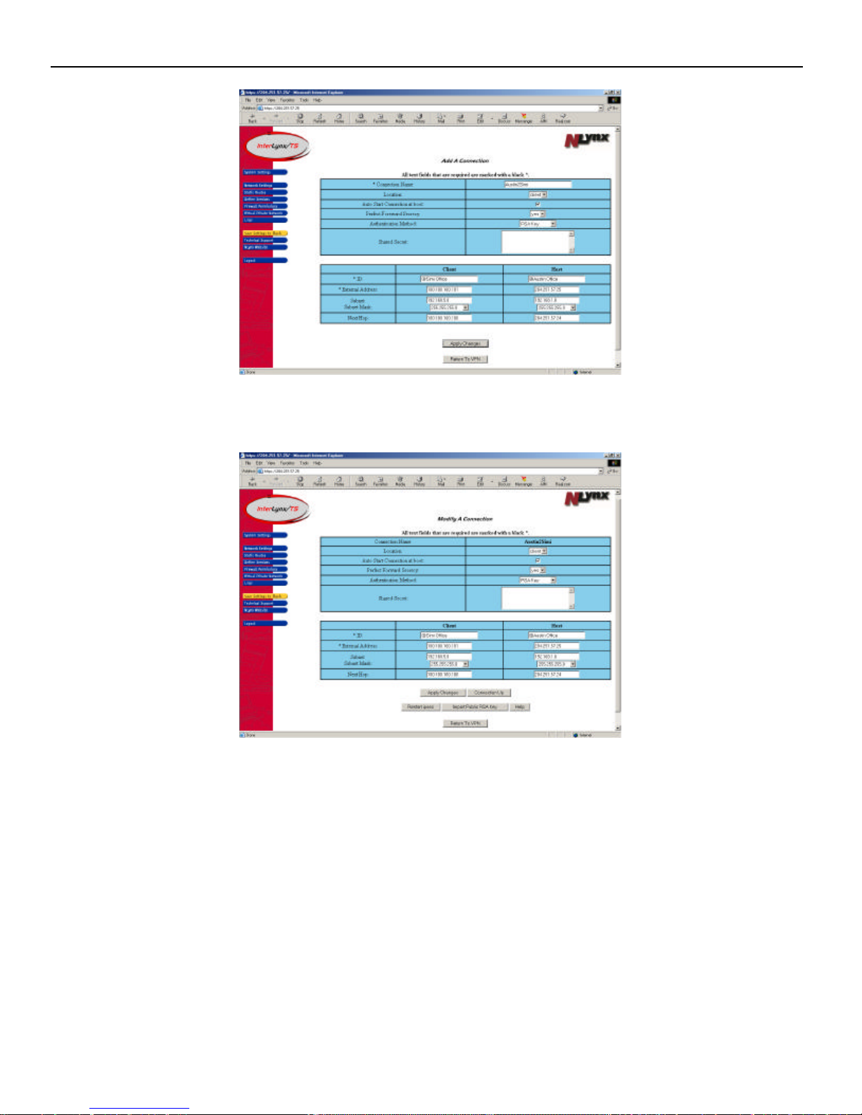
5. Once all these parameters are correctly entered, click on the Apply Changes button to add the
connection. The screen will refresh and display the parameters that were entered for that connection.
**NOTE: These parameters must be entered the same way on the other InterLynx/TS, except for the
Location setting. One InterLynx/TS must be configured as the Host and the other InterLynx/TS set for
Client. Remember to leave “Auto Start Connection at boot” unchecked on the host side InterLynx/TS.
8-3
Page 55
InterLynx/TS User’s Manual_________________________________________________________________
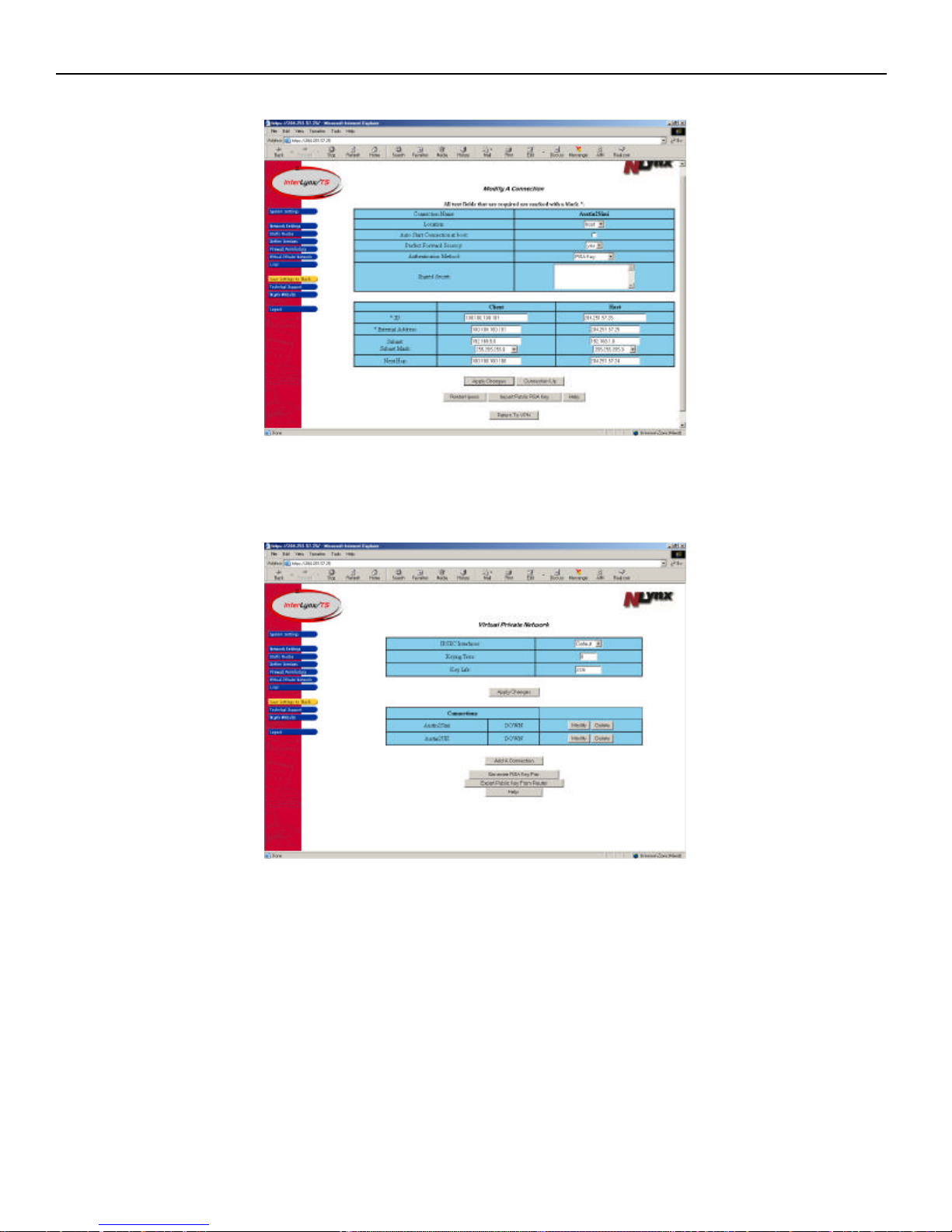
6. The Host side VPN configuration is shown below.
7. Click on Return to VPN to see all the VPN connections that have been configured for this
InterLynx/TS. This page will also show the status of the VPN (Up or Down).
8. Once the VPN(s) are done being configured proceed to the next section.
8-4
Page 56
InterLynx/TS User’s Manual_________________________________________________________________
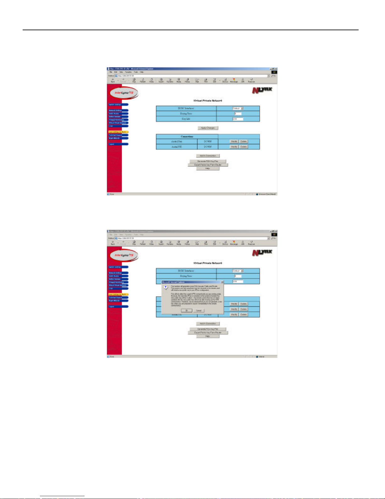
Part II – Generating the RSA KEY Authentication:
1. From the Virtual Private Network page press the Generate RSA Key Pair button to start the process
of generating the new key pair.
2. After pressing the Generate RSA Key Pair button, a dialogue box will appear to explain the key
generating process. After carefully reading the process, press the OK button to proceed.
8-5
Page 57
InterLynx/TS User’s Manual_________________________________________________________________
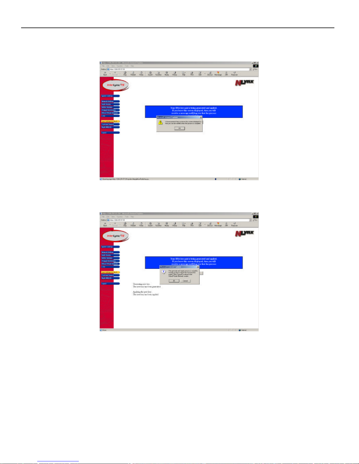
3. At this point the key generation process is taking place and another dialogue box will appear on the
screen asking you to keep the current page displayed, so that an acknowledgement can be displayed
when the key generation process has successfully finished. Press OK.
4. Once the key generating process is complete another dialogue box will appear asking if you would like
to export the public key from the router (InterLynx/TS). Press OK to continue the process.
8-6
Page 58
InterLynx/TS User’s Manual_________________________________________________________________
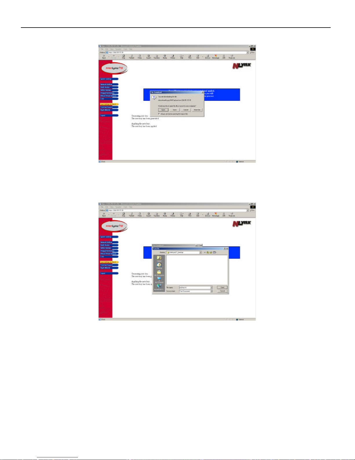
5. The next step of the process is saving the file to a PC by pressing the Save button.
6. After pressing the Save button, the Save As window will pop up so that the file can be stored in any
folder on the PC. Locate the folder that the key will be placed in and press the Save button to start the
download of the file to the folder on the PC.
8-7
Page 59
InterLynx/TS User’s Manual_________________________________________________________________
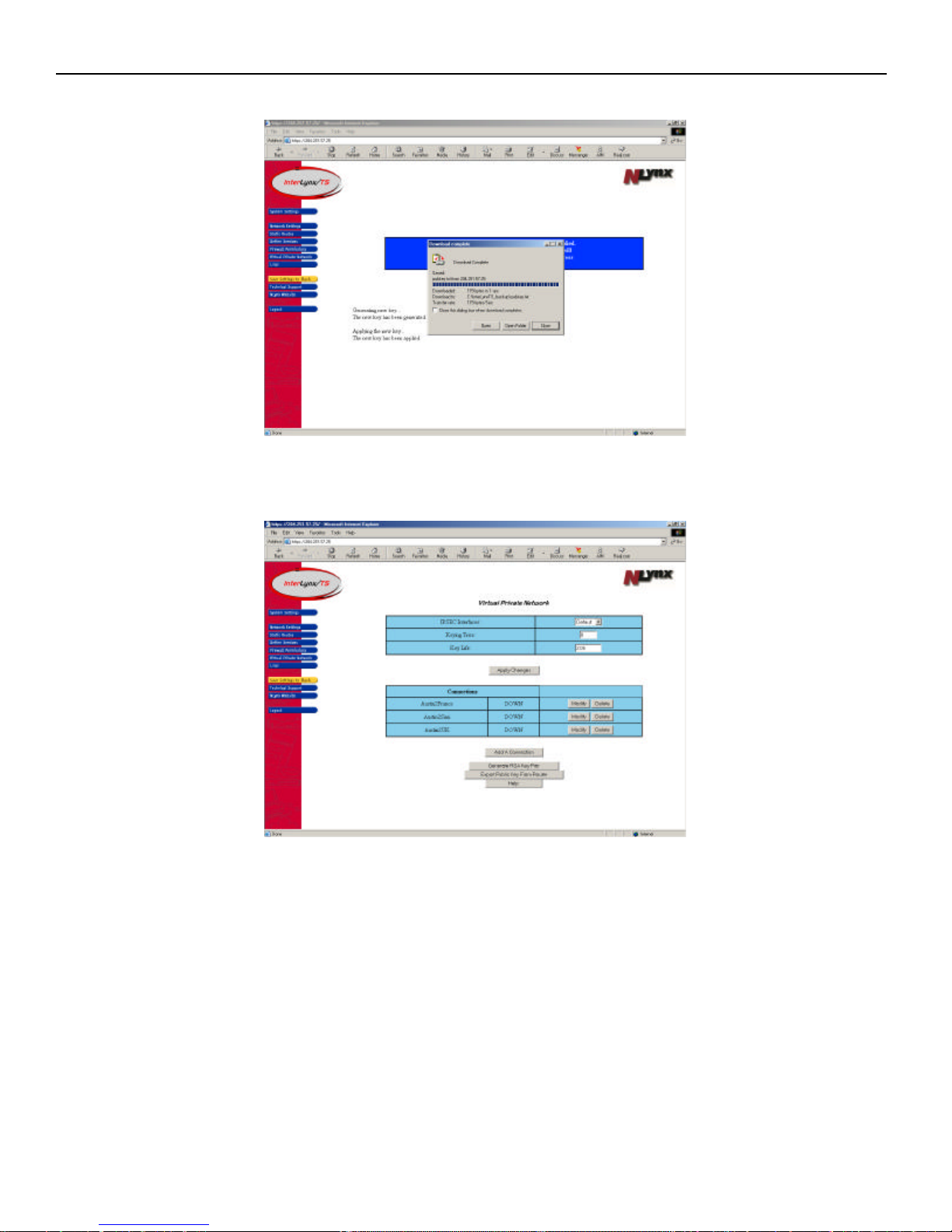
7. Once the download process is complete, press the Close button on the Download complete window.
8. When the download process is complete the RSA Key Generation page will be active, so press the
Return To VPN button.
9. At this point the RSA Key Pair has been generated and needs to be imported into the InterLynx/TS that
is at the other end of the VPN. Proceed to the next section for instructions on Importing the Public RSA
Key into the remote InterLynx/TS.
8-8
Page 60
InterLynx/TS User’s Manual_________________________________________________________________
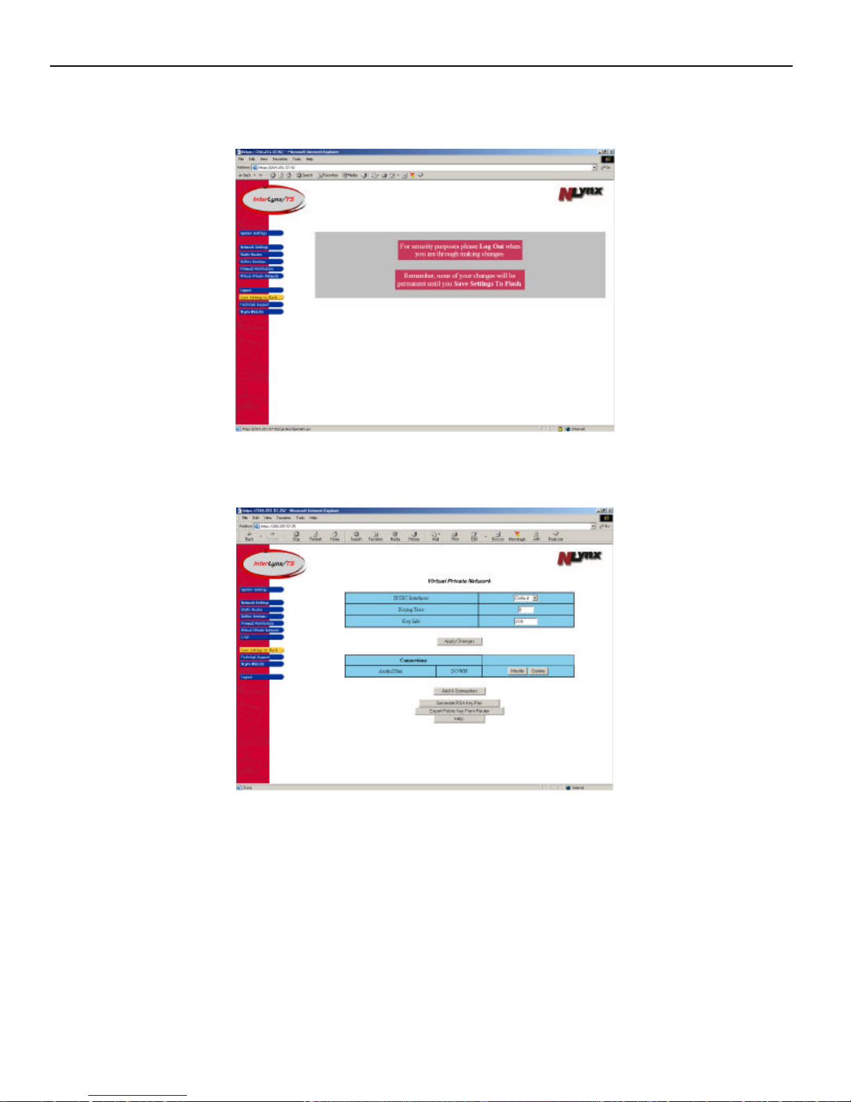
Part III – Importing the Public RSA Key into the remote InterLynx/TS:
1. Log into the remote (not the unit that the RSA Key was exported from) InterLynx/TS.
2. Click on the Virtual Private Network button on the left side of the screen. This will bring up the
Virtual Private Network page.
3. Click on the Modify button for the connection that was created. ( i e… Austin2Simi ) This will bring
up the Modify A Connection window.
8-9
Page 61
InterLynx/TS User’s Manual_________________________________________________________________
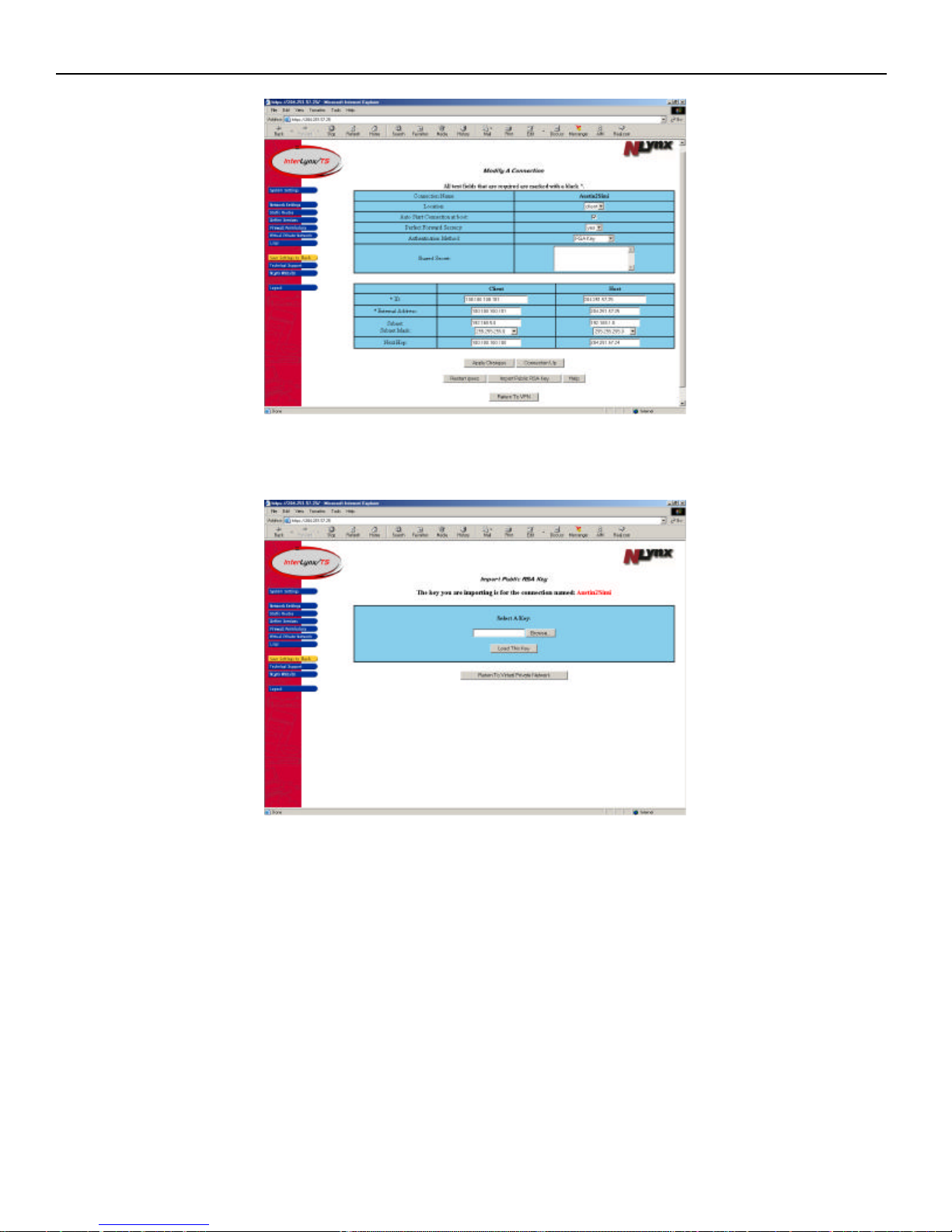
4. Press the Import Public RSA Key button to bring up the Import Public Key page and begin the
process of importing the public key to the router( InterLynx/TS ).
8-10
Page 62
InterLynx/TS User’s Manual_________________________________________________________________
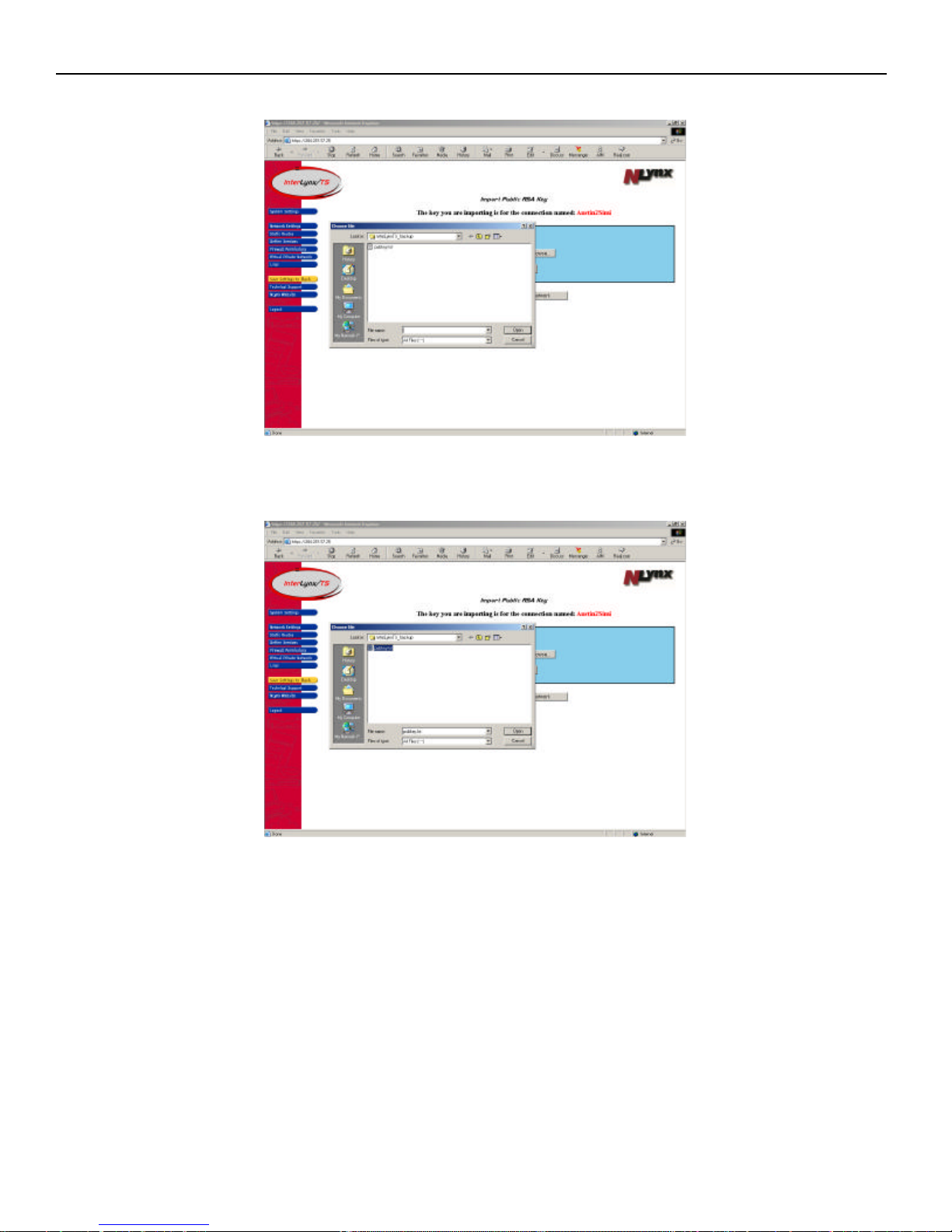
5. Click the Browse button to find the exported RSA Key that was saved as a .txt file on the PC.
6. Locate and highlight the file, and make sure it shows up in the file name text field. Press the Open
button to select the file. The Import Public RSA Key page will appear with the file name in the text box.
8-11
Page 63
InterLynx/TS User’s Manual_________________________________________________________________
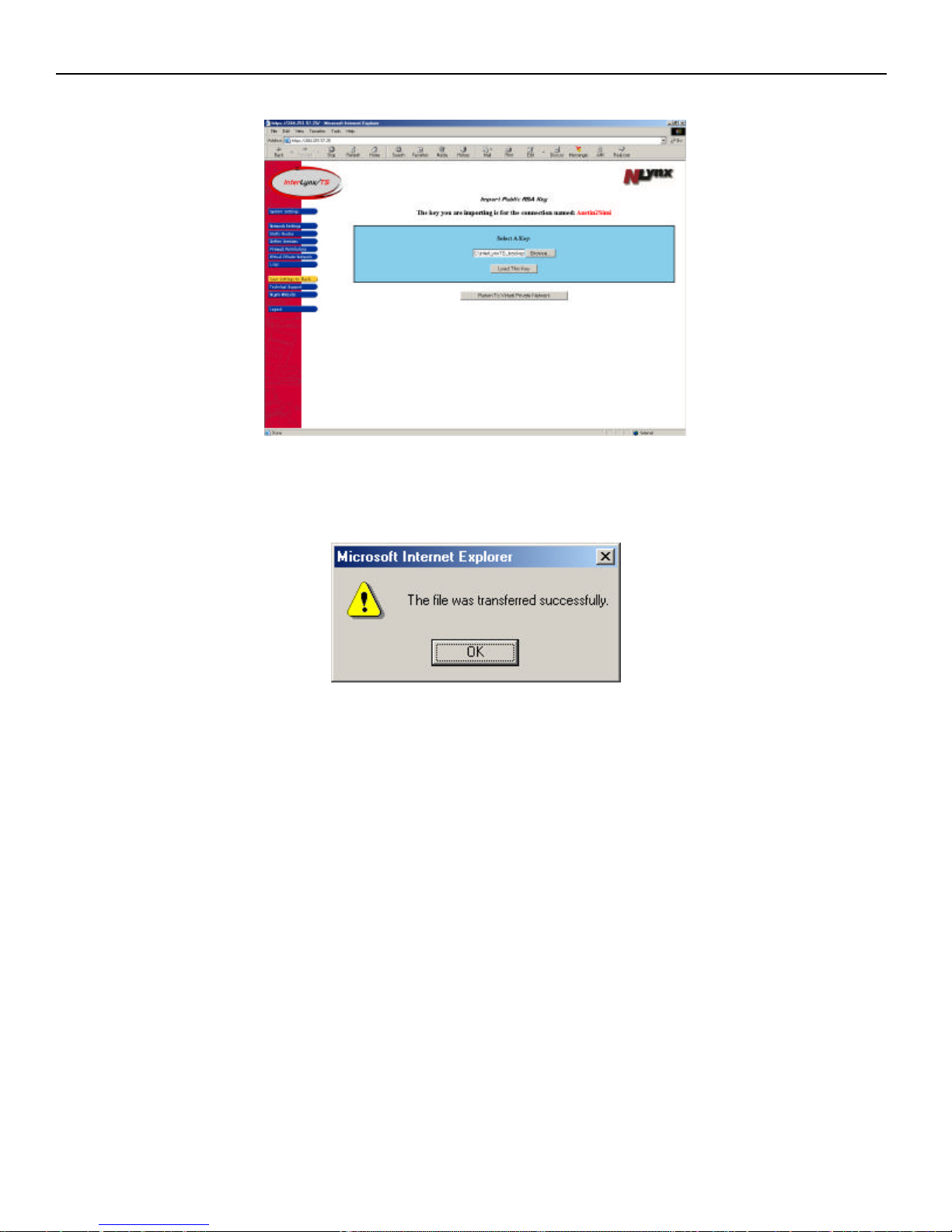
7. Press the Load This Key button to begin the import process to the InterLynx/TS.
8. After the file is successfully loaded onto the InterLynx/TS a message box will appear, choose OK and
then press the Return to Virtual Private Network button. At this point the configuration of the VPN
between the Host and the Client (remote) sites are complete.
*NOTE: The preceding process must be duplicated on the other InterLynx/TS after the
RSA Public Key is generated from the client InterLynx/TS. Follow the steps above until
you reach the saving the public key to the PC and make sure it has a unique name
associated with the Client side. ( i.e. simipublickey.txt ) and import it into the Host site
InterLynx/TS.
8-12
Page 64
InterLynx/TS User’s Manual_________________________________________________________________
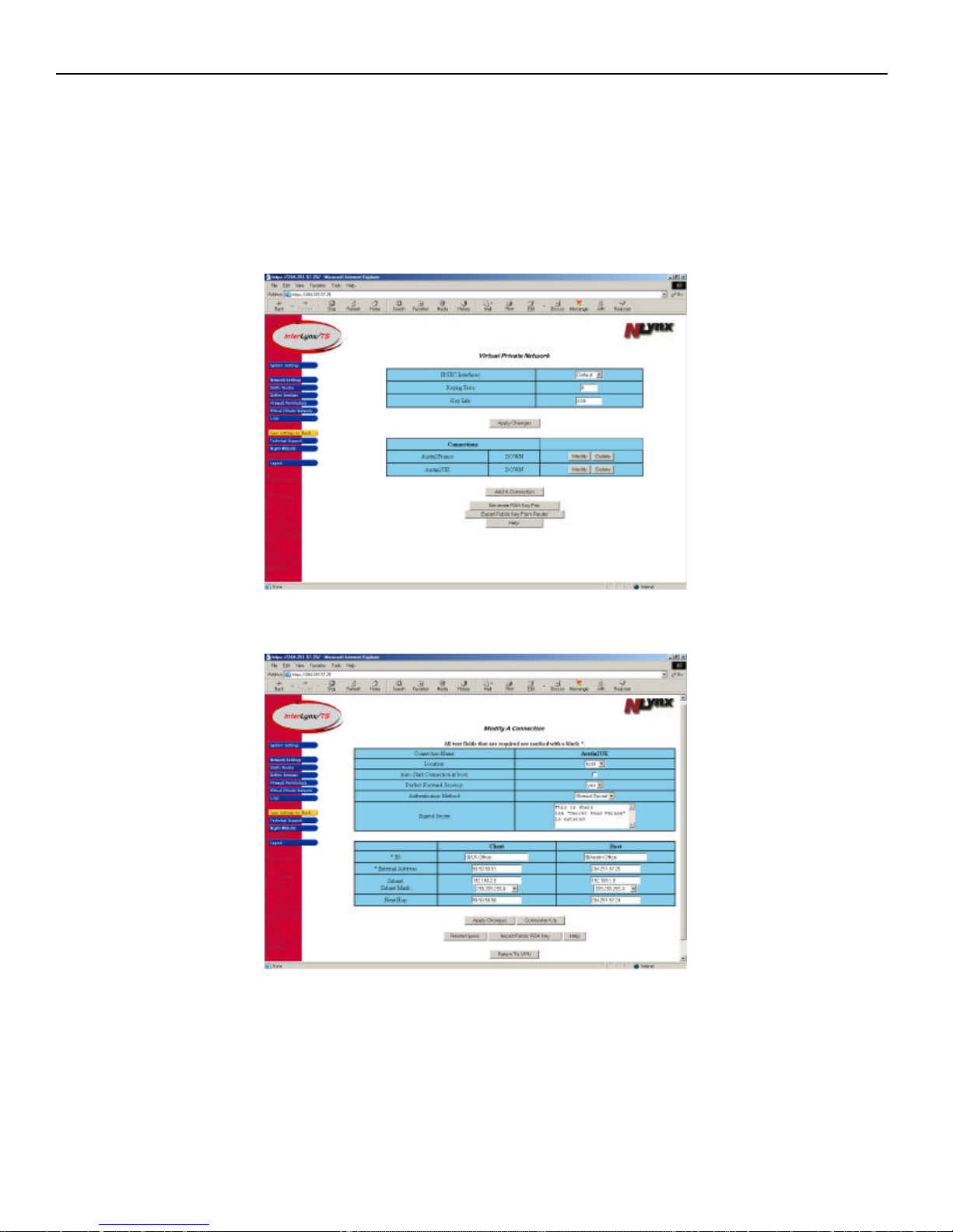
Part III – Restarting IPSec after a VPN connection has been configured.
Note: The instructions that are explained below must be implemented on the InterLynx/TS
configured as the Host first and then the Client (remote) InterLynx/TS. If this order is not followed
the units may not negotiate the VPN connection correctly and may require a manual start of the VPN.
1. Log in to the InterLynx/TS that is configured as the Host unit.
2. Locate the VPN connection that was just created and press the Modify button to open the Modify A
Connection page.
3. Click on the Restart IPSec button so the InterLynx/TS will run the new VPN settings.
8-13
Page 65
InterLynx/TS User’s Manual_________________________________________________________________
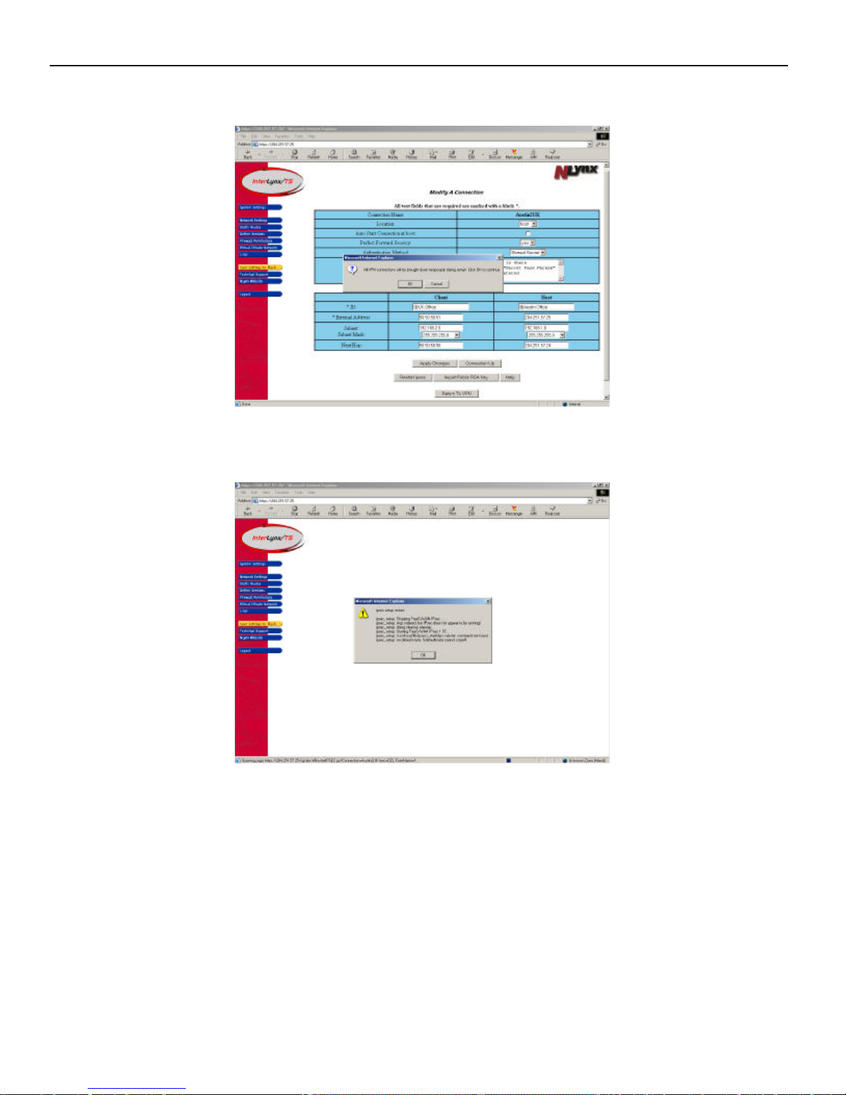
4. A dialogue box will appear stating that All VPN connections on the InterLynx/TS will be brought
down temporarily during restart. Click OK to continue.
5. A dialogue box will appear showing the IPSec restart process. Click “ok” to continue. This will put the
InterLynx/TS that is configured as a Host in a “ready” state.
6. Steps 1 – 3 must repeated on the Client (remote) InterLynx/TS so the new VPN settings can be
activated and allow the Client (remote) InterLynx/TS to initiate the VPN negotiation process,
since it is configured to Auto Start the Connection at boot (or when IPSec is restarted).
7. Click the Return to VPN button to view the VPN status for any VPN connections configured on the
InterLynx/TS.
8-14
Page 66
InterLynx/TS User’s Manual_________________________________________________________________
Chapter 9
_______________InterLynx/TS-to-InterLynx/TS VPN Configuration Using Shared Secret
NOTE: The recommended Security authentication method is RSA key. RSA key provides greater
security over Shared Secret in the fact that RSA key uses a Public and a Private key pair, where as with
Shared Secret the VPN devices share the same authenticate key.
Part I - VPN Configuration Instructions for Using Shared Secret:
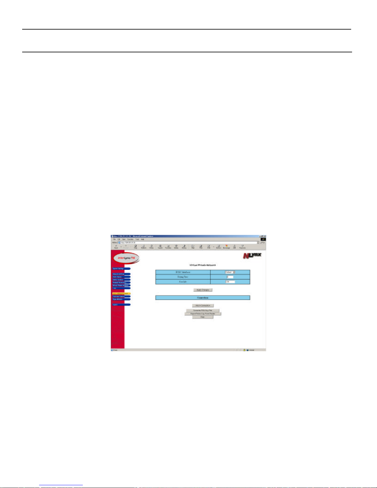
1. Click on the Virtual Private Network button on the left side of the screen. This will bring up the
Virtual Private Network page.
2. On the Virtual Private Network page, there are three settings that pertain to all VPN connections
configured on this InterLynx/TS:
a. IPSEC Interfaces:
• Default – This setting uses the default route in the routing table to determine
which External interface should be used for the VPN.
• Ethernet – Choose this setting to force the VPN to use the Ethernet interface.
• Dialup – Select this setting to force the VPN to use the Dialup interface.
b. Keying Tries – This is the number of times the units will negotiate the VPN or attempt to re-key
after the key has expired. Note: 0 equals continuous retries.
c. Key Life – The time in hours from successful negotiation to the key expiration. The value must
be entered in this format 3.0h (h stands for hours). The default is 2.0h.
9-1
Page 67
InterLynx/TS User’s Manual_________________________________________________________________
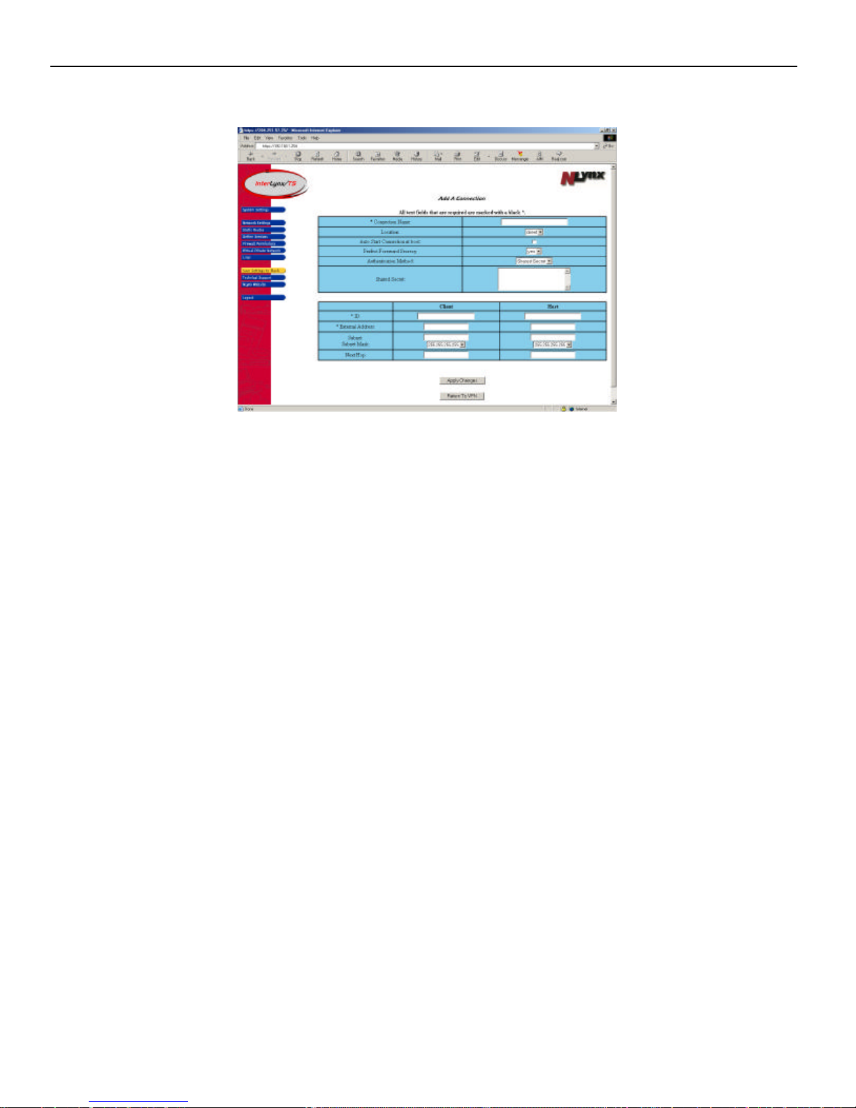
3. Click on the Add A Connection button. This will open the Add A Connection page to begin the VPN
configuration process.
4. In the Add A Connection page the following information is required to setup the VPN:
a. Connection Name This will be the name of the VPN. i.e. Austin2UK.
b. Location There are two choices here, Host side (corporate network) and Client side (remote
site).
c. Auto Start Connection at Boot When this box is checked, the unit will automatically try to
bring up the VPN connection when the unit is rebooted. (We recommend that the Client side
box be checked and the Host site box remains unchecked.)
d. Perfect Forward Secrecy The use of a short term key and a long term key so that if one key is
compromised the data is still secure. If both keys are compromised only the data associated with
that set of keys is vulnerable until the next re-keying sequence. Default is yes ( recommended)
e. Authentication Method There are two choices for authentication, rsasigkey and secret.
Choose Secret. Secret uses a Shared Secret pass phrase.
f. Shared Secret This is where the ”secret pass phrase” that will be shared by the VPN devices is
entered. NOTE: The Secret pass phrase cannot contain “”(double quotes) or a carriage
return. The pass phrase should not be found in a dictionary.
g. ID This will be the name given to each VPN device respectively. (we recommend that the @
sign be placed in front of the ID, this will suppress a DNS lookup on the DNS Server for the ID
name).
h. External Address This is the IP address associated with the external interface(the interface
connected to the router/internet) of each device.
i. Subnet This is the IP address range (the IL/TS default is 192.168.1.0) that is being used on the
internal side of the VPN device. Note: The internal subnets must be unique in order for the
VPN traffic to be passed thru the InterLynx/TS units. i.e. Both units cannot have the same
internal IP address range of 192.168.1.0.
j. Next Hop This will most likely be the Internet router for the network.
9-2
Page 68
InterLynx/TS User’s Manual_________________________________________________________________
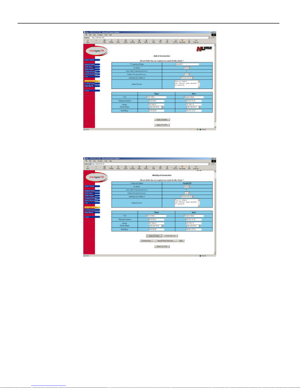
5. Once all these parameters are correctly entered, click on the Apply Changes button to add the
connection. The screen will refresh and display the parameters that were entered for that connection.
**NOTE: These parameters must be entered the same way on the other InterLynx/TS, except for the
Location setting. One InterLynx/TS must be configured as the Host and the other InterLynx/TS set for
Client. Remember to leave “Auto Start Connection at boot” unchecked on the InterLynx/TS configured
as Host.
9-3
Page 69
InterLynx/TS User’s Manual_________________________________________________________________
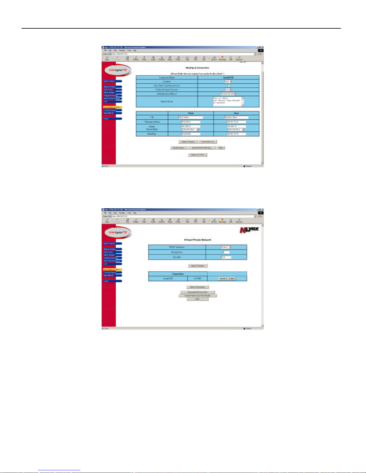
6. The Host side VPN configuration is shown below.
7. Click on the Return to VPN button to see all the VPN connections that have been configured for this
InterLynx/TS. This page will also show the status of the VPN (UP or DOWN).
8. Once the VPN(s) are done being configured proceed to the next section.
9-4
Page 70
InterLynx/TS User’s Manual_________________________________________________________________
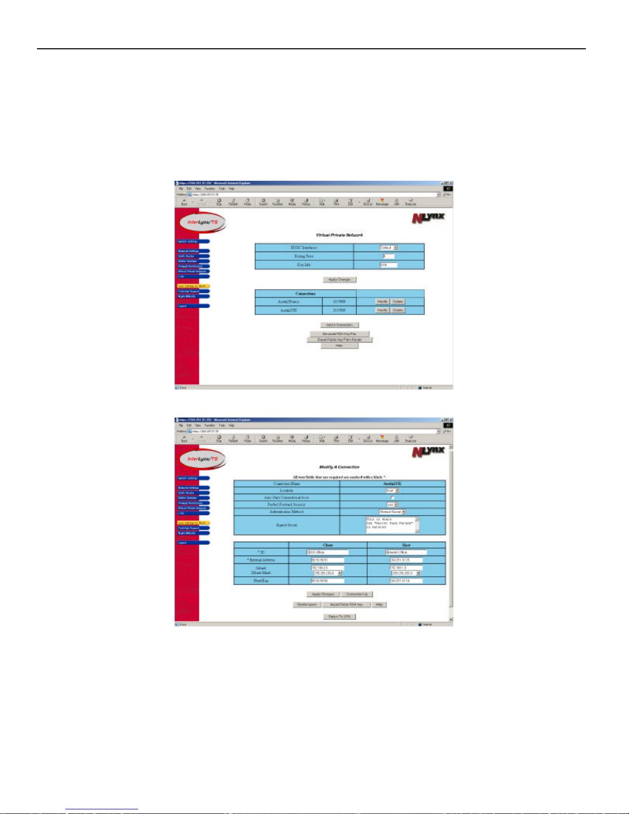
Part II – Restarting IPSec after a VPN connection has been configured.
Note: The instructions that are explained below must be implemented on the InterLynx/TS
configured as the Host first and then the Client (remote) InterLynx/TS. If this order is not followed
the units may not negotiate the VPN connection correctly and may require a manual start of the VPN.
1. Log in to the InterLynx/TS that is configured as the Host unit.
2. Locate the VPN connection that was just created and press the Modify button to open the Modify A
Connection page.
3. Click on the Restart IPSec button so the InterLynx/TS will run the new VPN settings.
9-5
Page 71
InterLynx/TS User’s Manual_________________________________________________________________
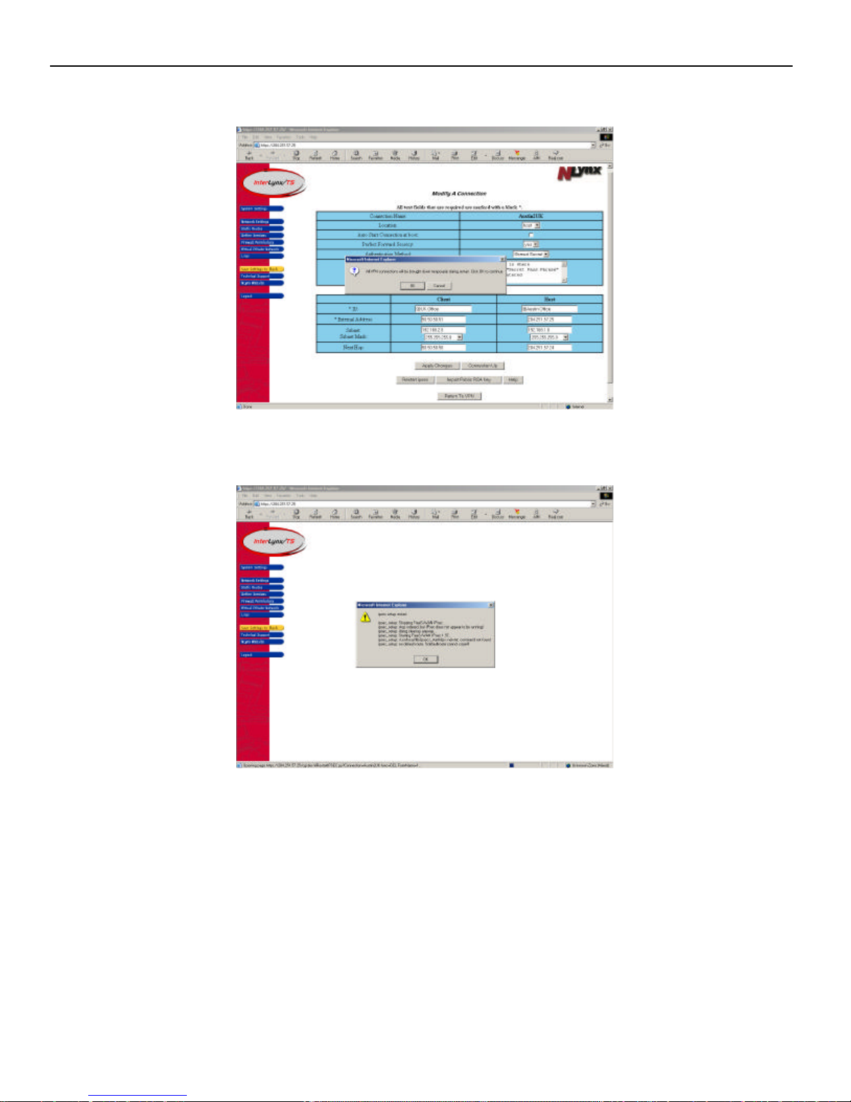
4. A dialogue box will appear stating that All VPN connections on the InterLynx/TS will be brought
down temporarily during restart. Click OK to continue.
5. A dialogue box will appear showing the IPSec restart process. Click “ok” to continue. This will put the
InterLynx/TS that is configured as a Host in a “ready” state.
6. Steps 1 – 3 must repeated on the Client (remote) InterLynx/TS so the new VPN settings can be
activated and allow the Client (remote) InterLynx/TS to initiate the VPN negotiation process,
since it is configured to Auto Start the Connection at boot (or when IPSec is restarted).
7. Click the Return to VPN button to view the VPN status for any VPN connections configured on the
InterLynx/TS.
9-6
Page 72
InterLynx/TS User’s Manual_________________________________________________________________
Chapter 10
______________________________________________________________________Logging
This chapter will cover viewing Log files, configuring for a Syslog Host, and IP Logging options.
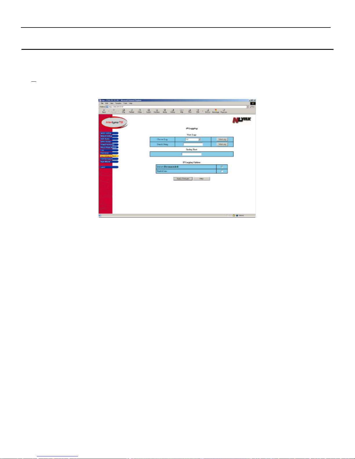
Enabling IP Logging
1. After logging into the InterLynx/TS, click on the Logs button on the left side of the screen. This will
open the IP Logging page.
2. The first step in setting up the logging on the InterLynx/TS is enabling IP Logging Options on one or
both of the network interfaces. It is recommended that IP Logging be enabled on the Internet interface.
Check the box to the right of the interface and then press the Apply Changes button.
Be certain to Save Settings to Flash if you want them to be permanent.
Viewing Logs
Logs can be viewed the following two ways:
• Choose Log:
a. All – shows the boot up messages as well as all IP traffic for the enabled interface.
b. IP Log – shows all IP traffic for the enabled interface.
c. IP Frag – shows fragmented packets that reached the interface.
d. Spoofed Addresses – private IP Addresses(spoofed addresses) trying to access the internal
network via the Internet will be logged.
e. PROTO=TCP – shows only TCP packets in the log for the enabled interface.
f. PROTO=UDP – shows only UDP packets in the log for the enabled interface.
g. PROTO=ICMP – shows only ICMP packets in the log for the enabled interface.
11-1
Page 73
InterLynx/TS User’s Manual_________________________________________________________________
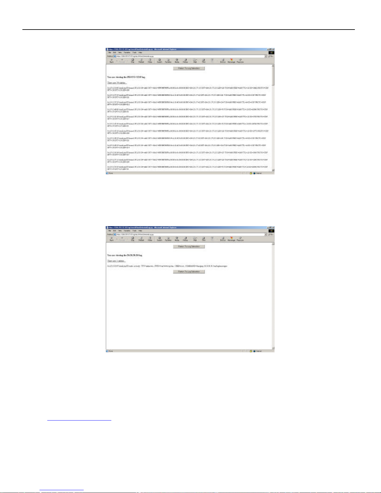
The following example shows the screen, when choosing to view PROTO=UDP:
• Search String – allows the log file to be searched using a specific string to search for. For example: If
you wanted to view all the Logs that had the IP Address of 50.50.50.50, then type the IP Address in the
Search String field and press the View Logs button. It will show all the Log files that contain that IP
Address.
Syslog Host
This option allows the Log files to be sent to an external machine that is running a Syslog Host. To
enable this feature type in the IP Address of the machine that is the Syslog Host and then press the Apply
Changes button.
NOTE: When this option is active, the log files will be unavailable to view from the InterLynx/TS. The
website www.kiwisyslog.com offers a free version of Syslogd Host for Windows NT/2000.
11-2
Page 74
InterLynx/TS User’s Manual_________________________________________________________________
Chapter 11
_____________________________________________________Print Server Configuration
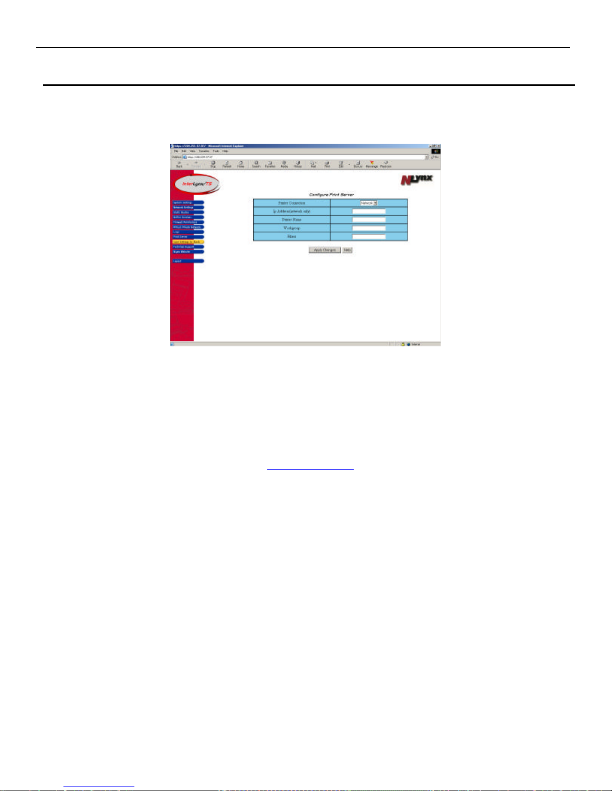
Configuring the Print Server on the InterLynx/TS:
Press the ‘Print Server’ icon located on the left hand side of the screen.
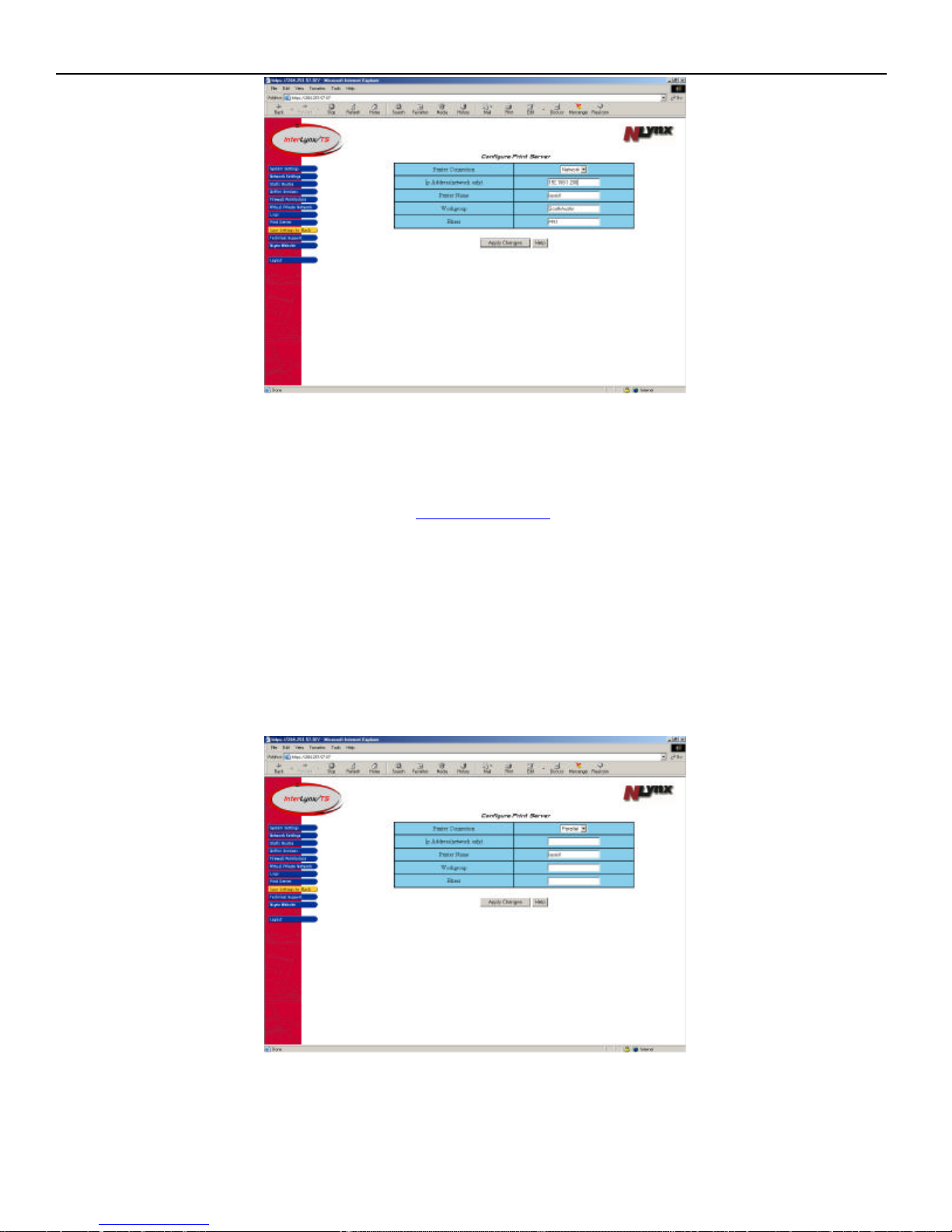
There are two ways to configure the Print Server on the InterLynx/TS. They are explained in the
following sections Network and Parallel.
• Network:
1. Choose Network in the Printer Configuration menu.
2. Enter an IP Address for the printer in the IP Address(network only) field.
3. In the Printer Name field, enter the name that will be displayed in the Windows browse menu.
The printer will be available as \\hostname\printer name. For example if the hostname of the
InterLynx/TS is gateway1 and the printer name is laser1, by browsing to “gateway1” in
Network Neighborhood, and double-clicking , “laser1” would be displayed as the available
printer resource.
4. In the Workgroup field enter the name of the Workgroup or Domain used by the local Windows
network. (Start | Help | Index Tab, then type Workgroup for Windows help on this topic)
5. Filters are sometimes used by network print servers to specify if and how data is to be filtered or
manipulated before being sent to the printer. Often there is an ASCII or Binary filter available
and the filter can be specified by naming the printer or filter with a specific name such as PR1.
This corresponds to the remote printer or “rp” field in the Unix printcap file.
6. After entering in the necessary information, press the Apply Changes button.
Be certain to Save Settings to Flash if you want them to be permanent.
4-1
Page 75
InterLynx/TS User’s Manual_________________________________________________________________
• Parallel
1. Choose Parallel in the Printer Configuration menu.
2. Skip the IP Address(network only) field.
3. In the Printer Name field, enter the name that will be displayed in the Windows browse menu.
The printer will be available as \\hostname\printer name. For example if the hostname of the
InterLynx/TS is gateway1 and the printer name is laser1, by browsing to “gateway1” in
Network Neighborhood, and double-clicking , “laser1” would be displayed as the available
printer resource.
4. The Workgroup field should be blank.
5. Filters are not necessary for parallel printing.
6. After entering in the necessary information, press the Apply Changes button.
Be certain to Save Settings to Flash if you want them to be permanent.
4-2
 Loading...