

NLS RFT2-17-CAT5 User Manual
NetCom User Manual
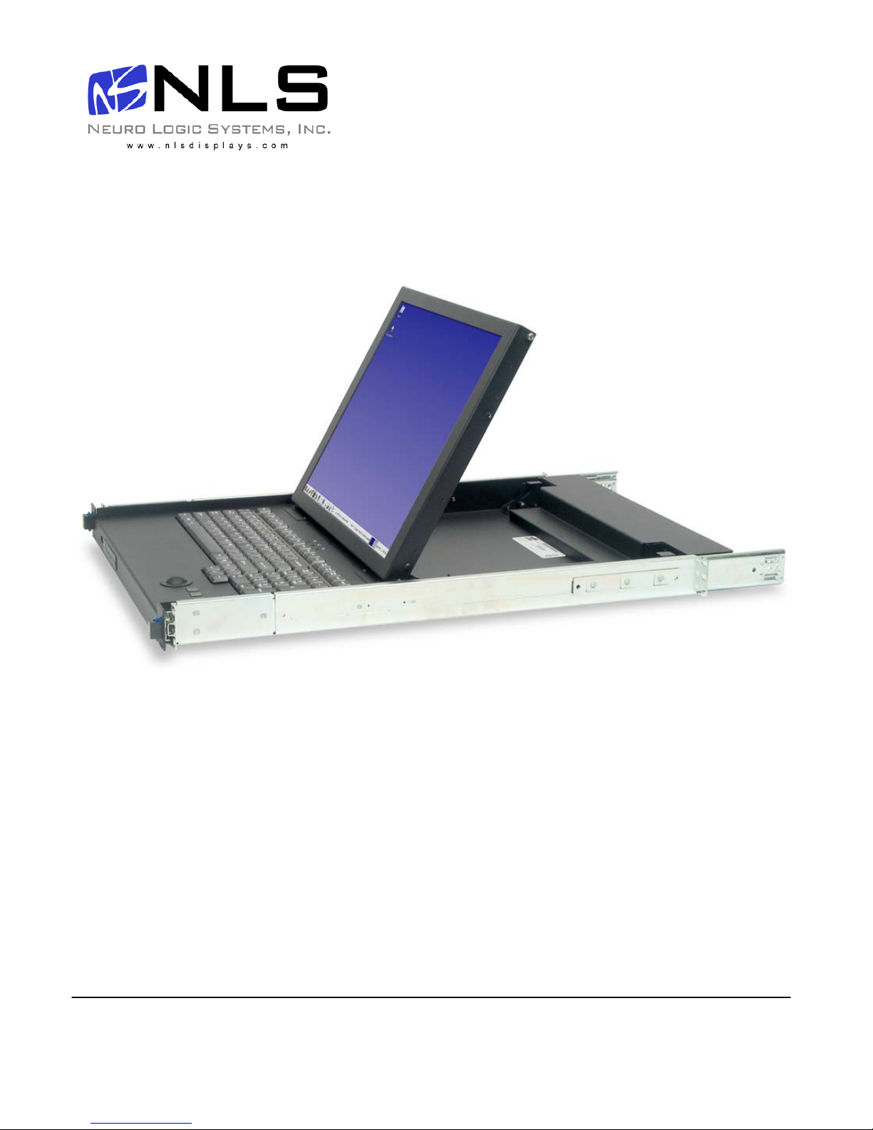
Installation guide for the RFT2-17-CAT5
into a 4-post 19-inch EIA cabinet
07/01/06 Rev 1.0 Page 1 of 24
Neuro Logic Systems, Inc.
451-C Constitution Ave., Camarillo, CA 93012
805.389.5435 • 805.389.5436 • www.NLSdisplays.com

Box Inventory
As you unpack the kit, ensure that you have the following items included in the box:
1 – 1U LCD with Keyboard
1 – 2m IEC Power Cable
1 – Cable Management System (unless ordered without)
2 – Outer Rails (Mounting to Rack)
2 – Inner Rails (Already mounted to RFT)
1 – Mounting Hardware
4 – Zip Ties for securing cables to the back of the unit
If any of these parts are missing, please call your local distributor or NLS at +1 805.389.5435 x21, or email
support@nlsdisplays.com to receive the missing parts.
07/01/06 Rev 1.0 Page 2 of 24

07/01/06 Rev 1.0 Page 3 of 24

Introduction
Access an d c ontrol mult iple multi-platform comput ers f rom one Keyboard Video Mouse (KVM) console
with the NetCom system.
1. Features
• Hot-Swap - disconnec t and reco nnect co mputers with out rebooti ng
• Scan-mo de operati on with varia ble time int erv al
• 1U Rack mountable
• Operate the system using an On Screen Display (OSD) keyboard hotkeys
• Create mult i-level cas c ade arrangements . Fo r ex ample by c as c ading the NetCom with Minicom ’s
Smart CAT5 KVM 16-Port model, connect up to up to 256 computers in the system
• The comput ers can be placed up to 10m/33f t f rom the NetCom
• Multi-platf orm — supports PS/ 2, SUN, and US B c omputers/s ervers
2. System components
The NetCom system consists of:
• NetCom 1 U 17” LCD and k eyboard with a digital 1 6-port KV M
• Remote Interface C onnection c ables
(RICCs) – PS /2, SUN, USB
• CAT5 cables (1.5m prov ided)
• RS232 Serial cable
• Rack mounts for the NetCom and the RICCs
3. Compatibility
The NetC om is compat ible with:
• PS/2, SUN and USB computers/servers
• VGA, SVGA, or XGA m onitors
• DOS, Windows (3X, 9X, 2000, NT 4, M E, XP, 200 3 Server) LINUX, UNIX, QNX, SGI , Fr eeBSD,
BeOS, Open VMS, N ov ell 3.12-6, Alpha U NIX, HP UX, SUN
07/01/06 Rev 1.0 Page 4 of 24

4. Pre-installation guidelines
• Switch off all c omputers
• Place cabl es away fro m fluorescent lights, air conditio ners , and machines that a re likely to ge nerate
electrical noise
• Ensure th at t he maximu m d is t ance betw een each computer and t he NetCo m, does not ex ceed
10m/33ft
5. Connecting the NetCom system
Connect each computer to the NetCom system using the appr opria te RICC and CAT5 cables. Error! Reference
source not fou nd . illustrates the NetCom system connections with the appropriate RICC connected to a PS/2, SUN
and USB computer/server.
07/01/06 Rev 1.0 Page 5 of 24
The RICCs
The RIC Cs draw their power from the comput er’s key board port (RICC PS/2, SUN) or from the U SB port
(RICC USB).
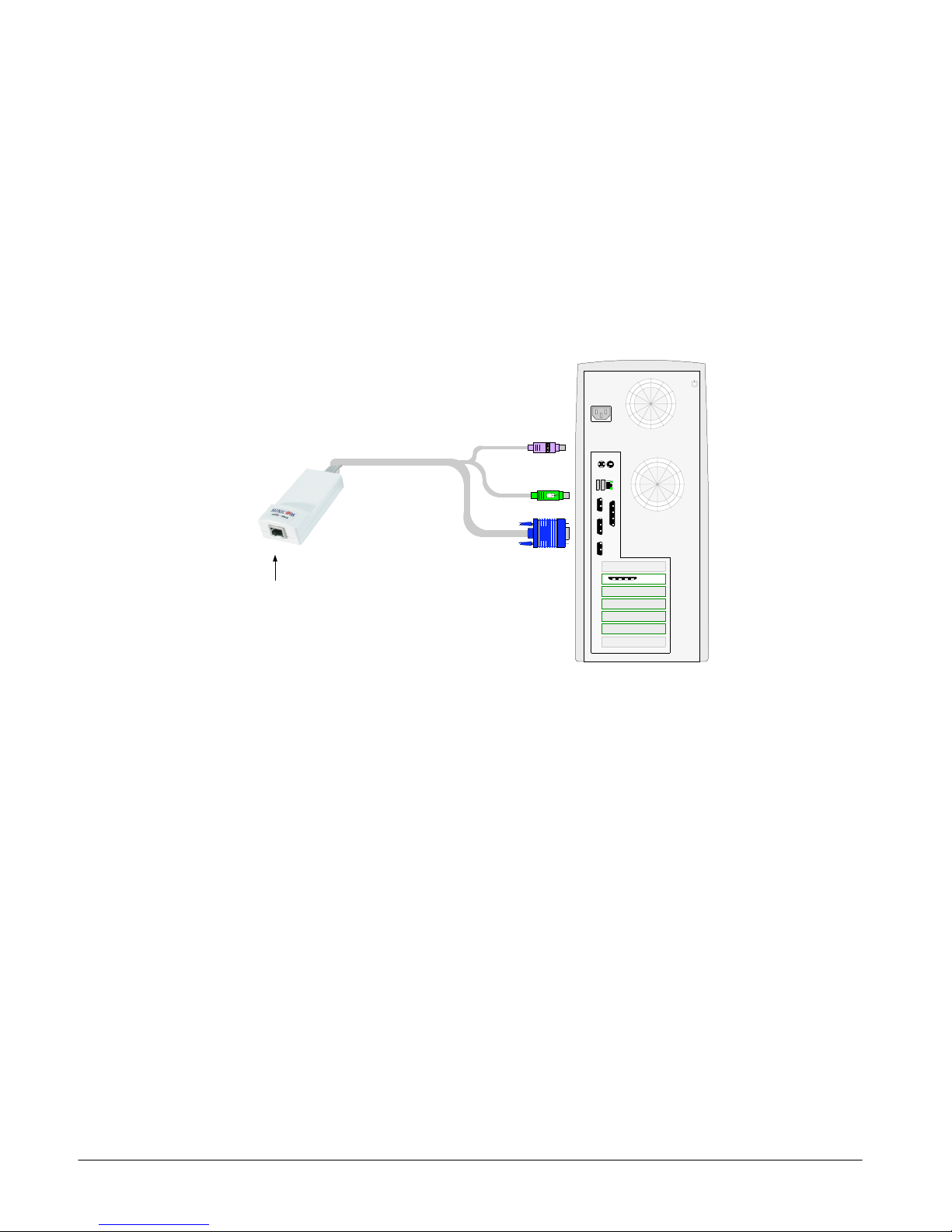
Connecting a PS/2 RICC
Figure 1 illus t rat es t he RICC.
To connect t he PS/2 RI C C:
1. Connect t he Screen connector t o t he comput er’s Video card.
2. Connect t he Keyboa rd c onnector t o t he comput er’s Keyboard port.
3. Connect t he Mouse c onnector to the comput er’s Mous e port.
NetServer tc2100
To computer’s
keyboard port
Mouse
Keybd
CAT5 cable to Smart
CAT5 Computer port
RICC
To computer’s
mouse port
To computer’s
Video card
100T
Parallel
VideoSerial A
Serial B
PCI 33Mx32b
PCI 33Mx32b
PCI 33Mx32b
PCI 33Mx32b
SCSI
Figure 1 PS/2 RICC
Connectin g a SUN Se rial RIC C
Above illus t rat es t he SUN RICC and its c onnections .
To connect t he SUN RIC C:
1. Connect t he Screen connector t o t he comput er’s Video card.
2. Connect t he Keyboa rd c onnector t o t he comput er’s Keyboard port.
Connecting a USB RICC
The RIC C US B s upports Wi ndows 98 SE and late r, MAC, SU N a nd SGI illustr at es t he USB RICC and its
connections.
To connect the USB RICC:
1. Connect t he Screen connector t o t he comput er’s Video card.
2. Connect the USB connector to the computer’s USB port.
07/01/06 Rev 1.0 Page 6 of 24

Connectin g the CAT 5 cab le s
1. Connect one connector to the RICCs RJ4 5 port.
2. Connect t he other connector to o ne of the NetCom’s Computer port s .
3. Follow the above 2 st eps f or each com puter.
Connectin g the KVM con sol e
To connect a KVM console to the NetCom:
1. Connect t he monitor’s c onnector t o t he NetCo m’s Monitor port.
2. Connect t he k eyboard ’s c onnector to the NetCo m ’s Keyboard port.
3. Connect t he mouse’s c onnector to the NetC om’s Mouse port.
6. Connecting the power supply
1. Connect t he NetCo m to t he power supply using t he Power cable provi ded. Use o nly power cord
supplied with the unit.
2. Switch on t he c omputers .
7. Resetting the Switch
Resettin g c an be perfor m ed throug h t he s of tware – ex plained lat er.
8. Avoiding general rack mounting problems
Elevated operating ambient temperature
The operat ing ambie nt t emperature of the rack environ m ent may be greater than t he roo m a m bient when
installing i nt o a c losed or multi-unit rack as sembly. So instal l t he equipm ent in an envir onment
compatible with the m ax imum rate d ambient t emperatur e.
Reduced airflow
Install the e quipment in a rack in such a way th at t he amount of airf low requi r ed for safe o peration is not
compromised.
Mechanical loading
Mount the equipme nt in t he rack in such a way th at a hazardous condit ion is not ac hieved du e t o uneven
mechanical loading.
Circ ui t ov er lo a di n g
When con nec t ing the eq uipment t o t he s upply circ uit , consider t he effect t hat ov erloading of c ircuits
might have on over-current pr ot ec t ion and sup ply wiring.
Reliable earthing of rac k -mounted equipment sho uld be maintained. Give attenti on t o supply connec t ions
other than direct conn ec t ions to the br anch circuit (e.g. use of power strips ).
07/01/06 Rev 1.0 Page 7 of 24

9. Cascading NetCom switches
You can cascade the NetCom system. You do so by connecting the lower level NetCom Switches to
RICCs. Follow the co nnections as illus t rated in the figure bel ow.
With the NetCom 16 Port model, c onnect up t o up to 256 com puters through casc ading.
A lower lev el Switch mus t have a diffe rent hotkey to dis play its OS D t han a highe r level swit c h. C hanging
the OSD display hotk ey is ex plained on page 12 below.
07/01/06 Rev 1.0 Page 8 of 24
 Loading...