

Page 1
iTerm2 Quickstart Guide
1U Rack Mounted General Purpose Terminal
Quick Start Setup Guide
06/01/06 Rev 1.0 Page 1 of 10
Proprie tary Infor ma tio n of N eu r o Lo gic Sy s t ems , Inc.
451-C Constitution Ave., Camarillo, CA 93012
805.389.5435 • 805.389.5436 • www.NLSdisplays.com
Page 2

iTerm Rack Kit Installation Guide
06/01/06 Rev 1.0 Page 2 of 10
Page 3

iTerm Rack Kit Installation Guide
SECTION 1
Introduction
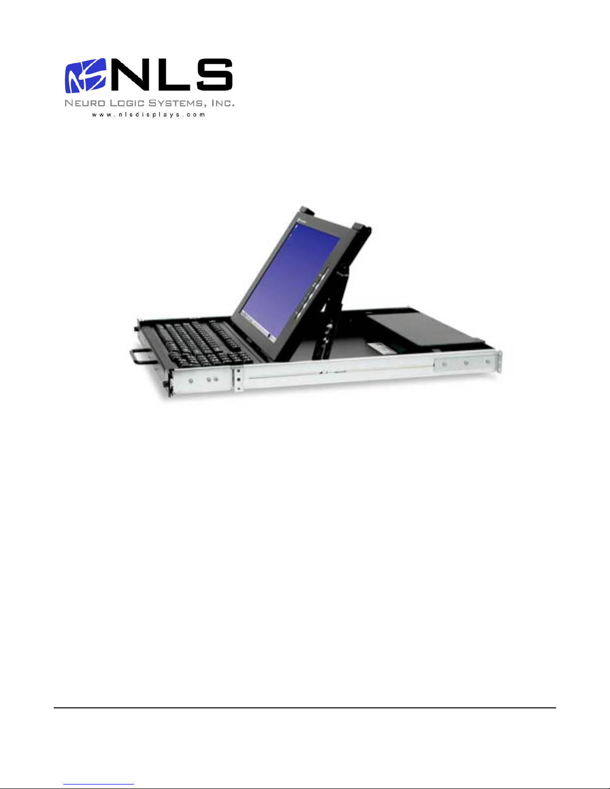
The 1U Terminal is a general purpose character terminal with a 15" colour LCD display and keyboard
mounted in a 1U high rack mountable tray.
The terminal connects to servers using either a serial RS232 console connection or an Ethernet
telnet RSC console connection (to the RSC Ethernet console port where available).
The terminal offers multiple personalities, and can connect to multiple servers when used with a
Console Server (for RS232 connections) or with an Ethernet Switch (for Ethernet connections).
This guide de scribes the bas ic installatio ns and configur ation proced ure. For further de tails,
please see the Reference Manual which is available at
http://www.nlsdisplays.com/pdf/docs/iterm/iTerm_v6-manual.pdf
06/01/06 Rev 1.0 Page 3 of 10
Page 4

iTerm Rack Kit Installation Guide
SECTION 2
Hardware Installation
Hardware installation consists of the following steps:
• Adjust and mount the removable slide rails in the rack.
The slide rails that the terminal tray is delivered with must first be detached from the terminal tray
by undoing the front thumb screws, extending the rails fully towards the rear (until they lock),
disengaging the exposed safety catch es (located midway along each side of the tray), and then
completely removing the rails towards the rear. The rail length shoul d then be adjusted to match
that of the rack by slackening the 3 bolts holding the extendible rear rail sections.
Bolt the rails into the rack using the 8 included bo lts. Please s elect a heigh t that ensures that the
terminal is easily visible, and where the keyboard can be used comfortably. Most racks will allow
the rails to be bolted from the front and rear of the rack. Very deep racks may require the back of
the rails to be bolted to an internal mid-rail within the rack, in which case the rear rail extensions
should be reversed so as to present the appropriate mounting holes to the rack mid-rails.
• Mount the terminal tray in the slide rails.
Ensure that the fitted rails are not extended (by c en teri ng the ca tches loca ted o n the inside edges
of the rails), and carefully slide the terminal tray into the fitted rails until it locks in to place. Please
note that forcing the terminal tray in to the mounted rails without making certain of a good fit may
cause permanent damage to the rail mechanisms. The terminal tray should slide easily when
fitted correctly.
When fully extended, the terminal tray will lock i n to position. The rail locks must be disengaged by springing
the catches located m id way along the sides of the terminal tray before it can be slid home.
06/01/06 Rev 1.0 Page 4 of 10
Page 5
iTerm Rack Kit Installation Guide
SECTION 3
Cable Connections
The terminal may be configured to communicate using either a serial RS232 connection or an
Ethernet telnet connection. Although it is poss ible to connect both RS232 and Ethern et cables, it is
only possible to use one type of connection at any time (depending on configuration defined in
terminal set up).
The Ethernet network connection may be used to connect to any 10Mb compatible Ethernet host
adapter. However the E thernet conn ection is most suited for use with RSC (Remote System Control)
Ethernet ports since these provide the same functionality as serial (ttya) console ports.
If connecting a serial RS232 cable to the server, it i s advisable to power down the server first.
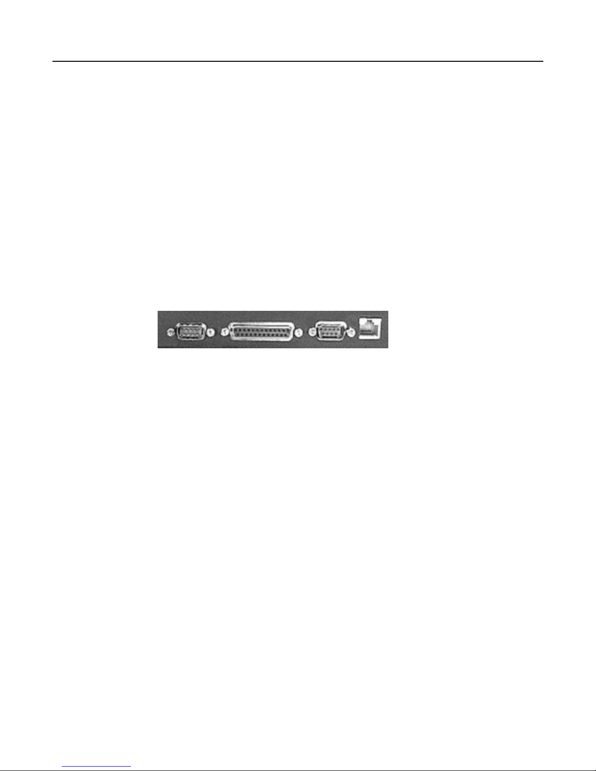
The rear of the terminal tray has the following connections.
SERIAL 2 PARALLEL SERIAL 1 10BASE T
• Serial 2 and Parallel
The terminal supports a local printer which can be connected to a serial (male 9-pin D connector)
or parallel (female 25-pin D connect or) in terface. Printe r cables are not included with the termina l,
and specific printers have not been qualified for this connection.
• Serial 1
This is a male 9-pin D connector port which should be used for a serial RS232 console
connection. The included cable can b e used to conn ect this port to a female 25-p in D connec tor
console port. The included 25-pin to 9-pin ad apter should be used in conjunction with this cable
when connecting to a male 9-pin D connector console port.
If your server has an RJ45 serial (RS232) port, connect the included 9-pin to 25-pin adapter
directly to the SERIAL 1 port at the rear of the terminal. Then use the RJ45 cable and RJ45 to
DB25 adapter (part number 530-2889) which are included with the server to connect to the
terminal.
When the terminal looses power or is powered off, a ‘break’ may be generated on the RS232 (SERIAL 1) host port (as is common with
most general pu rpose terminals).
06/01/06 Rev 1.0 Page 5 of 10
Page 6

iTerm Rack Kit Installation Guide
If connecting the terminal using the RS232 connection to a Console Server, use cabling recommended by the Console Server
manufacturer. In this case an alternate break sequence may not be required, since some console servers are “Break Safe”. Refer to the
Console Server documentation for details.
• 10Base T
This is an RJ45 port that may be used for an Ethernet server connection.
This connection may be used with any 10Mb compatible Ethernet host adaptor. However the Ethernet connection is most suited for use
with the RSC (Remote System Control) Ethernet ports since these provide the same functionality as serial (ttya) console ports.
Connect a RJ45 to RJ45 UTP cable (not supplied) between this port and an Ethernet 10Mb compatible hub or switch. The network
hub/switch should in turn be connected to the server RSC Ethernet port(s). The terminal supports 12 concurrent telnet connections when
configured in Econ-80 screen column mode. The number of concurrent telnet connections reduces to 8 when using standard 80 column
mode.
It is advisable that this network remain a private network for security reasons. If only one server is to be connected to by the terminal, a
crossover (or cascade) UTP cable may be used.
When using an Ethernet console connection, the alternate break sequence need not be defined.
However, the RSC Ethernet port must be configured using the “rsc-config” command.
Finally, connect the power cable, which terminates in a male IEC320 connector, to a
standard IEC320 socket in the rack.
06/01/06 Rev 1.0 Page 6 of 10
Page 7

iTerm Rack Kit Installation Guide
SECTION 4
Configuration
The terminal is deli vered largely pre- confi gured. This section describes configurati on for console serial or network connections.
Refer to the refer ence m anual f or details.
•
Switch on the terminal using the power switch located at the rear of the unit.
•
Raise the screen, and if the screen power LED is not lit, use the power button at the bottom of
the column of buttons located at the edge of the screen.
•
Hold down the ALT key and then depress the Esc key to enter Setup Mode.
•
Adjust the screen's brightness with the controls marked + and - located at the edge of the
screen.
•
If the screen image is not centered correctly, activate LCD auto-setup by pressing the ‘Select’
button (located second from bottom) at the edge of the scr een. This should only be done when
displaying the terminal setup screen.
To navigate the setup menus, use a function key to ent er a setup menu, an d then use the arrow keys
to highlight the field to be changed. Use the space key to change the value of a parame ter. Use F12
to return to the top level menu, and F12 again to leave setup mode. You will be prompted at this
point if the setup parameters are to be saved for future sessions.
The terminal is delivered pre-configured with the following settings which are suitable for most
RS232 serial console connections at 9600 baud using VT-100 emulation.
Disp SETUP Menu
Columns = Econ-80
Cursor = Blink Block
Screen Saver = Off
Lines = 24
Background = Dark
Page Length = 1 x Lines
Auto Page = Off
Width change clear = Off
ANSI Reverse = Off
Display= LCD
F4 Comm SETUP Menu
Baud rate = 9600
Data / Stop Bits = 8/1
Parity = None
Rcv Hndshake = Xon/Xoff
Xmt Hndshake = Xon/Xoff
Comm Mode = FDX
XPC Handshake = On
Printer Selection = Off
Multiple Sessions = Off
Ethernet Mode = Off
Auto Connect = Off
F2 General SETUP Menu
Personality = VT 100
Enhance = On
Status Line = Standard
Scroll Speed = Jump
Auto Scroll = On
End of Line Wrap = On
Rcvd CR = CR
Monitor = Off
Attribute = Char
F5 Misc SETUP Menu
Wprt Intensity = Dim
Wprt Reverse = Off
Wprt Underline = Off
Block End = US/CR
Ptr Baud rate = 38400
Ptr Data/Stop Bits = 8/1
Ptr Parity = None
Ptr Rcv Hndshake = Xon/Xoff
Ptr Xmt Hndshake = Xon/Xoff
Ptr Rcv = Off
F3 Keybd SETUP Menu
Keyclick = Off
Key Repeat = 5
Xmt Limit = None
Margin Bell = Off
Language = US
Keycode = ASCII
NRC = Off
Bell Volume = 2
NUM Start = Off
DEL Keypad = Dot/Del
F9 Lan Setup Menu
Local IP Address = {blank}
Netmask = {blank}
Gateway = {blank}
Remote IP 0..B Address =
{blank}
Port 0...B = 23
Term Type = vt100
Ethernet Node ID = (default}
06/01/06 Rev 1.0 Page 7 of 10
Page 8

iTerm Rack Kit Installation Guide
For use with an Ethernet connection the following parameters need to be configured:
• Display Setup (F1 in setup mode)
Page Length = 1*Lines (only required if ‘Multiple Sessions=On’)
• Communications Setup (F4 in setup menu)
Multiple S essio ns = off or on
Ethernet Mode = on
Auto Connect = off or on
‘Multiple Sessions=on’ should be set if multiple telnet sessions are required.
‘Auto Connect=on’ is used to prevent the need to press return to establish a telnet connection.
• LAN Setup (F9 in setup mode)
Local IP Address = IP address of the terminal
Netmask = Netm a s k value fo r th e netwo r k
Gateway = gateway address if required by the network
Remote IP 0 Address = IP address of first server Port = 23
Remote IP 1 Address = IP address of second server Port = 23
….
Remote IP B Address = IP address of twelfth server Port = 23
Term Type = Same as personality specified in General Setup menu
Ethernet Node ID = leave at default value
If only one host is be ing connected to, all tw elve Remote IP addresses and ports should be set
the same value.
Note: Eight separate telnet sessions are allowed if any columns other than Econ-80 is selected in
Terminal Display set up. If Econ-80 is selected, the Multiple Sessions option allows twelve
concurrent telnet sessions to be used.
Once the terminal has been co nfigured, press F12 to promp t if the setup is to be saved. Selec t Yes
by pressing space and then press F12 again to exit setup mode.
If any IP addresses or Ethernet settings have been defined or edited, the terminal must now be
power cycled by using the switch at the rear of the terminal (ensure that no serially connected host is
present prior to power cycling the terminal).
If the host server is connected and active, pressing return (if Auto Connect was set to off) should now
display a server login prompt.
Each of the defined servers may be selected by using ALT and a function key. For example to
connect to a server which has been defined as Rem ote IP Address 3 , press ALT and Function Key 4
(since the IP addresses are defined from 0 to 11 and the function keys are labeled 1 through to 12).
When connecting to a server which is switched off or does not have telnet configured, a 10 second
timeout will occur when the serv er is selected (if Au to Connect is on), or af ter pressing return when
the server is selected (if Auto Connect is o ff). During this 10 second timeout, it is not p ossible to
select another server or enter setup.
Please ensure that the Page Length is set to ‘1*Lines’ in the Display Setup (F1 in setup) to prevent possible
problems when switching between different servers.
06/01/06 Rev 1.0 Page 8 of 10
Page 9
iTerm Rack Kit Installation Guide
SECTION 5
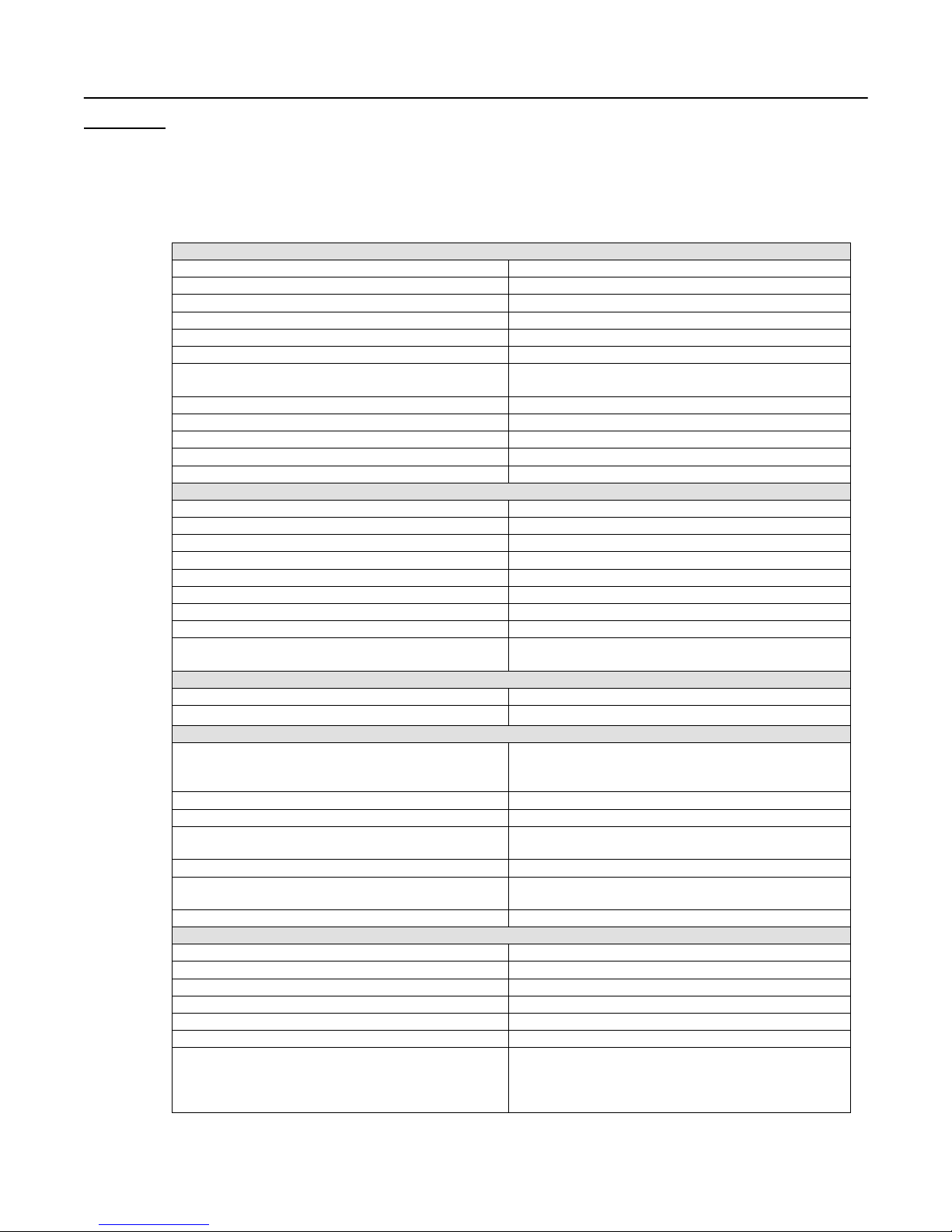
Specifications
Physical
Dimensions 44mm x 483mm x 615mm HxWxD
Weight 13Kg
Temperature 0°~40°C operating, -20°~60°C storage
Humidity 5% to 95% non condensing
Power Supply Auto-ranging 90-262 VAC, 47-63Hz
Power Consumption 60W (max), <25W (standby)
Cables Included Power (IEC320), 3m RS232 termi nati ng in DB25M,
DB25F-DB9F adapter
Rack mount kit Included for Sun & most EIA 19” racks
Standards CE, FCC
Installation User Installable
Warranty 12 months RTD (return to depot)
Maintenance Contact Sun Support for options
LCD Panel Specifications
Screen size 15.1” visible diagonal
Resolution 800x600
Controls contrast, brightness, auto- adjust, colour
LCD Power switch Automatic with m anual over ride
Brightness 250cd/m (typical)
Contrast 300:1 (typical)
Viewing Angle L/R=75°/75°, U/ D=55° /65°
Screen protect ion 2mm glass
LCD Approvals FCC-B, CE, VCCI-II, BSMI, CCIB, UL, CUL, TUV,
CB, TCO’99
Keyboard Specifi cati ons
Type 101 key
Layout US
Terminal Emulation
Emulations VT52, VT100, VT220, Console ANSI, PC TERM,
TVI910+/925, WY-50+, WY-60, WY-100, WY-120,
WY-325, PCG Alpha
Character matr ix
Screen size 80x25
Page length 1, 2, or 4 screens (singl e-screen page length only
Cursor Blink or steady, bl ock or underline
Modes Full duplex, half duplex, block mode, half block
Colour modes 16 f oreground and 16 background colours
Communicati on Ports
Serial port for host connect ion One DB9M RS232 port
Network port One RJ45 10Base-T Ethernet port
Local printer por ts DB25F Parallel and DB9M RS232 port
Serial baud rates 50 to 115,200 bps
Data format 7/8 data bits with/without parity, 1/2 stop bit s
Serial handshake XON/XOFF, XPC, and hardware DTR
Communications options Single RS232 server connection, or up to 12
7x12 dot matrix in 10x16 cell
when using multi ple telnet sessions)
mode
Ethernet telnet sessions to predefined IP
addresses. Both ser ial and Ethernet connections
can not be used concurrent ly.
06/01/06 Rev 1.0 Page 9 of 10
Page 10

iTerm Rack Kit Installation Guide
06/01/0 6 R ev 1.0 Page 10 of 10
 Loading...