


SuperK COMPACT
Instruction Manual

This product is protected by intellectual property rights including one or more of the following granted or pending patents:
US 6611643; US 6796699; US 6888674; US 6898367; US 7123408; US 7466885; US 7679822; US 7787503; DE 10313987; DE 10331906; CN 101430476;
AU 2004304019; EP 1164400; EP 1184701; EP 1706788; EP 2045643;EP 1164406; EP 1164406; JP 2002098896; US 2002006264; JP 2002082286; EP
1184701; EP 1184701; DE 20122782; US 2002009260; US 2002028044; DE 10331906; WO 2005006042; US 2006165359; JP 2009513994; EP 1644765;
US 2009074023; WO 2005062113; NO 20063369; JP 2007515680; HK 1102937; EP 1697793; CN 101430476; CN 1898597; CN 100445858; CA 2544871;
AU 2004304019; EP 1706788; WO 2005071483; US 2008226242; AT 445175; DE 10115488; DE 10115589; US 2009086315; JP 2010102345; EP 2045643;
EP 2045642; EP 2045641; EP 2045641; DK 1184701; DE 10115590; DE 10115577; DE 10115509; DE 10115487; DE 10115486; AT 407381; EP 1164400; JP
2002055284; DE 20122783; US 2005122580; DE 10313987; WO 2005024482; US 2007025662; JP 2007504499; EP 1714187; DE 10340964; US
2010040335; WO 2008083686; EP 2111564; CN 101681079; CA 2675234; EP 2332892; WO 2010003422; US 2011116283; EP 2307915; US 2011019701;
WO 2009095022; EP 2238655; US 2010296529; WO 2009076967; EP 2223396; WO 2009095023; US 2010329292; WO 2010115432; US 2008226242; WO
2005071483; EP 1706788; AT 445175; WO 2009024490; DE 102007039498; EP 2181350;
GB 2380812; US 6792188; US 6972894; GB 238423; US 6856742; US 6892018; GB 2394712; US 7155097; AU 2002338639; CN 1535389; JP 4203320;
US 7174078; GB 2397135; US 7349611; AU 2002336075; EP1421420; FR1421420; DE 602 17 684.0-08; UK 1421420; AU 2002350398; US7327922; US
7221840; US 7266275; US 7289709; AU 755223; GB 1086393; US 6845204; US 6542681; AU755547; GB1086391; US6539155; US 7321712; US
7305164; US 7366388; US 7245807; AU 771646; AU 2004202828; CA 2362997; CN ZL00803964X; CN ZL 200410088155; DK 1153325; DK 1340725;
EP 1340725; FR 1153325; FR 1340725; DE 1153325; DE 60025766.5-08; IN 211164; KR 637542; SE 1340725; GB 1153325; GB 1340725; US 6954574;
US 6888992; AU 767773; CNZL 00803960; DK 1153324; FR 1153324; DE 1153324; IN 211165; KR 647378; GB 1153324; US 6631234; US 6990282; US
6853786; GB 2380811; DK 1388018; FI 1388018; FR 1388018; DE 602 22 111.0; IT 1388018; GB 1388018; US 7116875; US 7106932; GB 238435; GB
2403219; US 7346249; GB 2407390; US 7224873; CN 1143147; DE 0991967; GB 0991967; GB 2341457; KR 509720; US 6334019; US 6603912; US
6301420; AU 763796; CNZL 00808310X; GB2 350 904; RU 2226705; SG 83969; US 09/937715; EP 1153325; US 2004/0105641; EP 1340725; EP
1385028; AU 767773; US 6631324; EP 1236063; US 2003/0077058; EP 1236059; US 2003/0059185; EP1388018; EP 1385796; WO 2004/027475; WO
03/062160; WO 03/058308; WO 03/058310; GB 2389915; WO 03/058309; WO 03/093884; WO 03/080524; WO 2004/001461; WO 2004/001465; WO
2004/057393; WO 2004/057392; US 2004/0028356; WO 2004/057391; WO 2004/057394; PCT/GB98/01782; WO 0060388; AU 763796; AU 0038274; CA
2368778; CN 1353824; HK 02107625.6; IN/PCT/200101191/MUM; JP 2000-609822; KO 10-2001-7012566; NO 20014740; PL 0350990; RU 2226705; SG
83969; JP 2002541507; EP 1166160; US 6792188; US 6542681; EP 1460460; EP 1442323; GB 2397135; DE 69917776; WO 04053550; AT 0268482; WO
04049025; DE 69917022; EP 1086393; EP 1421420; AT 0266214; WO 0241050; EP 1086391; GB 2394712; WO 03078338; WO 04019092; GB 0329442;
EP 1381894; WO 03100488; GB 0320733; WO 03079077; WO 03079074; WO 03078338; GB 2384323; GB 2384323; GB 0310466; GB 0310466; WO
03032039; CA 2445487; GB 2380812; GB 2380812; GB 0302866; GB 0302866; WO 03019257; CA2445280; WO 02101429; WO 02101429; CN 1385399;
AU 0755547; AU 0755223; WO 02088801; WO 02084350; CA 2443037; WO 02072489; AU 0223515; WO 0241050; WO 0241050; AU 0214944; WO
0239159; EP 1181595; AU 0179603; WO 0214944; AU 0181741; WO 0212931; WO 0212931; EP 1086393; EP 1086391; AU 0035509; WO 0060390; CA
2368789; CA 2334554; CA 2334510; US 7305164.
Issue: 1.5
Published: May 2018
Copyright © 2018 by NKT Photonics A/S. All rights reserved. Reproduction or
translations of any part of this work is prohibited.

P a g e | 1
Table of
Contents
Table of
Contents ................................................................................................................................................. 1
Section 1: General ........................................................................................................................................... 2
Section
2: Laser Safety .................................................................................................................................... 3
2.1 General information and designated use .............................................................................. 3
2.2 Labels used on the SuperK COMPACT .................................................................................... 3
2.3 Safety hazards ........................................................................................................................ 5
2.4 Laser safety goggles ............................................................................................................... 5
2.5 Laser safety compliance list ................................................................................................... 6
2.6 Supply power .......................................................................................................................... 6
2.7 Key Switch ............................................................................................................................... 7
2.8 Remote Interlock .................................................................................................................... 7
Section
3:
Equipment
description and installation ....................................................................................... 10
3.1 Installation ............................................................................................................................ 10
3.2 Operating conditions ............................................................................................................ 10
3.3 Front Panel ........................................................................................................................... 11
3.4 Rear
Panel
........................................................................................................................... 12
Section
4: Operation and System Menu ....................................................................................................... 13
4.1 Precautions ........................................................................................................................... 13
4.2 Laser operation .................................................................................................................... 13
4.3 SuperK COMPACT with FC output connector ...................................................................... 17
4.4 SuperK COMPACT with collimated output ........................................................................... 17
Section
5:
Display
messages ........................................................................................................................... 19
5.1 Warning and error messages ............................................................................................... 19
Section
6:
Trigger input and remote connection
............................................................................................... 20
6.1 Trigger operating modes ...................................................................................................... 20
6.2 Remote interface connection ............................................................................................... 21
6.3 External Trigger input ........................................................................................................... 21
6.4 Coax trigger input ................................................................................................................. 21
6.5 Industrial trigger input ......................................................................................................... 22
6.6 Logic and analogue pulse output ......................................................................................... 22
Section
7: Service & Support ........................................................................................................................ 23
7.1
Service and storage
............................................................................................................. 23
7.2 Fiber tip cleaning .................................................................................................................. 23
7.3 Technical s
upport
................................................................................................................ 24
Section 8: Specifications
of the
SuperK
COMPACT ........................................................................................ 25
8.1 Electro-mechanical Specifications ........................................................................................ 25
8.2 Optical Specifications ........................................................................................................... 25
8.3 System dimensions ............................................................................................................... 26
Section 9: Accessories for the SuperK COMPACT ......................................................................................... 27
User Notes 28

P a g e | 2
Section 1: General
Introduction Please take the necessary time to read this instruction manual, which contains
important information on safety issues concerning the usage of this equipment.
The safety might be seriously impaired if the instruction manual is not followed
carefully.
Also, make sure to follow the instructions on how to unpack the SuperK COMPACT
from the shipping box if this is not already done.
The equipment comprises a laser Class 3B. It is recommended, that only
persons familiar with laser safety regulations and coherent light should operate
this equipment.
Do you have any questions concerning this product, please do not hesitate to
contact us.
This manual covers the SuperK COMPACT with the following model numbers:
SuperK COMPACT, model# S024-010-000 (FC/PC output connector)
SuperK COMPACT, model# S024-010-010 (FC/APC output connector)
SuperK COMPACT, model# S024-010-020 (Collimator output connector)
Performance The SuperK COMPACT has a broad spectrum ranging from app. 450 nm up to
above 2400 nm. The spectral power density is divided between >20% power in
the visible part of the spectrum and <80% power in the IR spectrum. A typical
output spectrum (limited to 2400nm by the measurement equipment) is
presented in figure 1.1.
Figure 1.1: Typical spectral performance of the SuperK COMPACT.
As performance may vary between individual laser units, please refer to the
SuperK COMPACT test reports for specific information on laser output
performance.
It is recommended to keep this manual in connection with the SuperK COMPACT
unit for operator reference.

P a g e | 3
Section
2: Laser Safety
Introduction Never attempt to switch on or operate the SuperK COMPACT before reading,
understanding and fully familiarizing yourself with the contents of this chapter.
2.1 General information and designated use
General The NKT Photonics SuperK COMPACT™ is classified as a Class 3B
laser product as
per the IEC/EN 60825-1:2014 laser safety standard and complies with FDA
21CFR 1040.10 and 1040.11 except for deviations provided in laser notice 50
(June 2007).
Intended usage
The SuperK COMPACT has been designed for general laboratory use and is as
such not approved nor tested for use in treatment or diagnostics of human or
animals and does not comply with European, US or rest of the World
requirements for medical device lasers. Neither is the system appropriate for
outdoor use or use in extreme conditions such as elevated/lowered
temperatures, particle/chemical contaminated environment or vacuum
conditions.
Laser Safety Officer
The SuperK COMPACT should only be used by staff familiar with laser safety
procedures and in facilities appropriate for laser operation. NKTP recommends
appointing a Laser Safety Officer (LSO) in accordance with valid local and
national safety regulations. The LSO should ensure that every user of the
system is familiar with the safety aspects of the laser unit and that the manual
should be clear and present to operators of the laser. Furthermore, any other
staff in close proximity of the SuperK COMPACT should be aware of any risk in
connection with usage of the unit.
2.2 Labels used on the SuperK COMPACT
Label type The SuperK COMPACT is equipped with a range of labels with dedicated
information regarding safety and product information. Please take time to identify
each label on the SuperK COMPACT before using it for the first time.
Figure 2.1: The side of the SuperK is labeled with laser warning label and explanatory label

P a g e | 4
Warning Labels The warning label pl a c e d on t h e si d e of t h e l ase r alerts the
user:
This product is a Class 3B laser.
The unit emits visible and invisible laser radiation from the optical output,
marked on the front panel.
Avoid direct exposure to the beam.
Figure 2.2: The output fiber contains a warning label placed 10 cm from the output
connector
The warning label placed on the armored output fiber alerts the user of the laser
aperture at the end of the output fiber.
Figure 2.3: The output collimator contains a warning label.
The warning label placed on the output collimator alerts the user of emission of
radiation from the output end of the collimator.
Avoid eye or skin exposure to direct or scattered
radiation.
Always wear
safety goggles matched for the
wavelength
spectrum while
operating
the
laser. Make sure that there
are
no reflective materials in the path of the
beam.
Warranty labels
There are 2 warranty labels. One is placed on the cover and the other on
the collimator. If any of the seals are broken, removed or otherwise
damaged, warranty on the SuperK COMPACT will be void. For service or
support on the system, please refer to section 7.3: Technical support.
Figure 2.4: Warranty void label placed on the cover of the SuperK COMPACT.

P a g e | 5
Serial number
A label identifying the part number and serial number of the SuperK
COMPACT is placed on the side of the top cover. Please refer to this label
whenever contacting NKTP for service or support.
Figure 2.5: Serial number identification label
The label contains the following information:
Manufacture of the system
Product description
Product number
Product serial number
Manufacturing date
Regulatory compliance
2.3 Safety hazards
Hazards The output laser beam from the SuperK COMPACT can cause a number of hazards
if not handled correctly. The following potential hazards should be considered:
Fire hazard
Skin burn
Eye injury
Care should especially be taken when using a SuperK COMPACT with collimated
output beam as the beam will pose a potential fire and skin/eye hazard over a
larger distance than when using a COMPACT unit with FC connector output.
Fire Hazard The laser beam can cause fire if the full beam or even just parts of the beam is
obstructed or guided towards flammable materials such as paper, solvents or other
similar combustible material. Keep the beam path free from any such parts and
keep a fire extinguisher in close range of the operation area of the SuperK
COMPACT.
Skin burn Even though the SuperK COMPACT is only a Class 3B laser unit, focused IR light
from the unit could cause potential skin burn. Avoid any contact between laser
beam and skin or wear appropriate skin protection if operation close to the beam is
required.
2.4 Laser safety goggles
Eye safety Due to the broad band nature of the SuperK source it is not possible to achieve full
protection from the output laser light using laser safety goggles. However, a
significant level of protection can be achieved by choosing appropriate type of laser
goggle and follow some simple rules of laser safety:
Always wear laser goggles when operating the output beam in free space
(e.g. using free space optics like mirrors and beam splitters/filters).
Always have a controlled beam path and investigate any possible
reflections/stray light.

P a g e | 6
Always ensure secure positioning of the output connector (PC or
collimator connector).
Avoid any reflecting parts close to the beam path which is not a part of a
specific setup.
Avoid any easily flammable parts close to the beam path (e.g. lens tissue
and solvents).
NKT Photonics recommend using a combination of several different filtertechnologies (absorption and interference). Absorption filters can be edge filters
as well as band pass filters. Only the combination of these filters makes it possible
to solve complex requirements for broadband light source laser applications. The
IR5D filter from NoIR Laser Company, LLC is among the most suitable product
available. Full protection is not achieved, but many alternatives are significantly
worse.
Figure 2.6 depicts the optical density of the IRD5 filter indicating the transmission
of visible green light.
Figure 2.6: Optical density as function of wavelength for the IRD5 filter
2.5 Laser safety compliance list
CE approval The SuperK COMPACT is CE-marked and has been tested for FCC and VCCI
compliance as well.
FDA Compliance The SuperK COMPACT complies with FDA part 1040.10 and 1040.11 except for
deviations provided in laser notice 50 (June 2007).
UL and CSA The equipment is not UL- or CSA approved.
2.6 Supply power
The SuperK COMPACT must be supplied with 100 – 240 VAC through a standard
power cable with an IEC type C13 appliance plug, and must be connected to
protective earth through this cable. A cable is supplied with the SuperK COMPACT,
but it may be exchanged with a compatible type, compliant with the local
regulations.
Main Power Switch With the power cable inserted into the socket on the back panel the SuperK
COMPACT is turned ON by means of the main power switch on the front panel. A
green LED indicating “POWER ON” turns on as well as the display on the front
panel.

P a g e | 7
2.7 Key Switch
Key switch The SuperK COMPACT is equipped with a key switch on the front panel. The key
must be switched to the ON position before laser light can be emitted. Whenever
the unit is not in use, the key should be removed and kept in a safe place. The
laser unit cannot be operated when the key is in the OFF position and the key
cannot be removed whenever it is in the ON position.
2.8 Remote Interlock
Remote Interlock A remote interlock safety system is provided with the SuperK COMPACT to lower the
risk of accidental exposure from the laser. An interlock socket is located on the
reverse side of the SuperK module. The socket is to be used together with a
remote interlock system e.g. a door interlock or similar.
The principle connection diagram of the interlock is shown in Figure 2.9.
SuperK Accessory The external bus socket also placed on the back panel can be used to connect
accessories to the module. External interlocks placed on these accessories are
connected to the module through the external bus. If a SuperK Accessory is not
present, the laser cannot be operated unless the supplied interlock defeater for external
bus (External Bus Terminater) is inserted in the external bus port. See figure 2.7.
Figure 2.7: Interlock Defeater for External Bus (External Bus Terminater)
LEMO The SuperK COMPACT is delivered with a LEMO connector Type 0B to interface to
the interlock connection.
Figure 2.8: LEMO Type FGG.0B.302 connector for interlock socket.
Operation
Inserting the LEMO connector:
Push the connector into the socket until the locking mechanism ’clicks’. The red dot
on the connector and socket indicates the correct orientation.
Figure 2.10: Inserting the LEMO Connector

P a g e | 8
Disengaging the connector:
Grab the connector by the sliding release sleeve (the textured area) and pull it
away from the socket. The release sleeve will slide over the main body of the
connector and accordingly disengage the locking mechanism.
Figure 2.11: Removing the LEMO interlock connector
Warning The two leads of the LEMO connector must be closed through an external interlock.
Due to safety, if the interlock circuit is not closed the laser will not operate. If the
interlock connections are left open they will prevent the laser from operating.
It is not recommended to operate the laser without an appropriate
interlock connection to e.g. a door or enclosure around the system. If users
bypass this safety feature, NKT Photonics bears no responsibility on
damage, loss or harm caused by accidental laser exposure.
Safety interlock The remote interlock circuit operates on 5V D.C. The total resistance (including
cable and switch) should not exceed 40 Ω. Typical signal current in remote circuit is
43 mA.
Interlock circuit specifications:
Voltage range: Min. 0 V; max. 12 V
Voltage, operational (Norm): 5 V
Current, operational (Nom): 43 mA
Short circuit current (Max): 80 mA
Figure 2.9: Principle connection diagram for a remote interlock system in connection with a
SuperK COMPACT.
Figure 2.9 shows a diagram of a simple remote switch interlock system. When the
switch is open (A) the electrical circuit is open, and the laser emission is shut off.
A
B

P a g e | 9
When the switch is closed (B) the circuit is closed and it is possible to have laser
emission.
The remote switch interlock enhances safety, as it shuts off laser emission if the
door switch to the room or enclosure where the system is located is opened.
If the interlock circuit is opened during operation, the interlock circuit must be reset
before laser emission can be initiated again.
Cable
The Interlock cable can be up to 5 meters long and it can be a non-shielded type. If
a cable longer than 5 meters is required, we recommend using a shielded type of
cable.

P a g e | 10
Section
3:
Equipment
description and installation
3.1 Installation
Unpacking Upon unpacking the system, please allow time for the module to reach ambient
temperature conditions before installation as the module may have a temperature
outside the specified temperature range due to transportation.
Installation Install the SuperK COMPACT in a horizontal position resting on all four feet placed
underneath the unit. There should be at least 7.5 cm (or 3 inch) of free space in
front and behind the unit. This is to ensure access of cables and allow airflow for
cooling. Do not stack anything on top of the unit. Keep the unit away from warm
or cold sources.
Electrical connection The SuperK COMPACT requires access to a power socket and a power cable with
an IEC type C-13 plug. No other connections are required in order to operate the
SuperK COMPACT.
3.2 Operating conditions
The SuperK COMPACT is specified to operate in the range of 15-30°C in a non
condensing environment. The output fiber should not be coiled to less than 10 cm
diameter. Do not expose the units to vibrations or mechanical shock during
operation.

P a g e | 11
3.3 Front Panel
The SuperK COMPACT can be operated entirely via the front panel interface.
Figure 3.1: Front panel of the SuperK COMPACT system.
(A) On / Off SWITCH
Turns the electrical power on/off to the laser.
(B) KEY SWITCH
Enables/disables interlock or laser emission
from the SuperK COMPACT. The key must be
turned to “ON” for the SuperK COMPACT to be
able to emit light.
(C) SELECTION WHEEL
Used to navigate the control menus.
(D) CONTROL BUTTONS
Three control buttons are present on the front
panel. The Return button, the Emission
button, and the Enter button.
(E) INDICATOR LEDs
Three indicator LEDs are present on the front
panel. The green power LED will light when
power is supplied to the module; the red
emission LED will light when emission is on;
the yellow pulse overrun LED will light when
the current pulse width cannot support the set
frequency.
(F) DISPLAY UNIT
System information display. See Section 5 for
details.
(G) OUTPUT FIBER
The output fiber is a non-linear crystal fiber
with a 0.20 NA (@1060nm). The fiber is
terminated with either an FC/PC, FC/APC
connector, or a collimator unit. A black fiber
boot indicates an FC/PC connector and a green
fiber boot indicates an FC/APC connector. The
non-linear crystal fiber is placed in an armored
jacket in case of a collimated output.
F
E D C
B
A
G

P a g e | 12
3.4 Rear
Panel
The rear panel of the SuperK COMPACT contains access for communication, power,
interlock connection and trigger input/output.
Figure 3.2: Rear panel of the SuperK COMPACT system.
(A) Power socket
100V-240V/50Hz-60Hz
(B) Interlock socket
Connector for interlock cable (LEMO connector)
(C) USB
USB interface. See Section 6 for details
(D) External Bus
Sub D-15 connection to SuperK Accessories or
Interlock Defeater for External Bus (Bus
Terminater)
(E) Coax trig input
BNC connector for coaxial external trigger
(F) Industrial trig input
Input for isolated external trigger
(G) Logic pulse output
BNC output port for logic signal with the laser
frequency
(H) Analog pulse output
BNC analog output signal of pulse emission
signal
(I) RS-232
Port for communication via RS-232
I
H
G
A
B C D E F
P a g e | 13
Section
4: Operation and System Menu
4.1 Precautions
Warning Make sure at all times during system operation, that the beam path is known and
controlled. Wear suitable protection and ensure everyone in the laser area is
aware that the system is in operation. Ensure that remote interlock is in place.
The SuperK COMPACT is not equipped with a back reflection isolator. Make sure to
minimize external back reflections into the laser. External back reflections can
compromise performance and ultimately damage the laser.
4.2 Laser operation
Operating the
SuperK COMPACT Use the following procedure to turn on the SuperK COMPACT once it is installed
(see section 3.1):
1
The power switch and key switch are set to
“
OFF”.
2
Connect the interlock cable (LEMO connector) to
the socket labeled
“Interlock” on the back panel
as described in section 2.8.
3
Connect the power cable to the connector labeled
“100V - 240V, 50 Hz -60 Hz” on the rear panel.
4
Remove dust protection cap from the fiber
connector and be aware of the light path out from
it. Insert into appropriate connector fixture (FC
adaptor or Collimator receptacle).
5
Consider cleaning the fiber facet before operation
using appropriate fiber cleaning methods.
Please refer to section 8: Service.
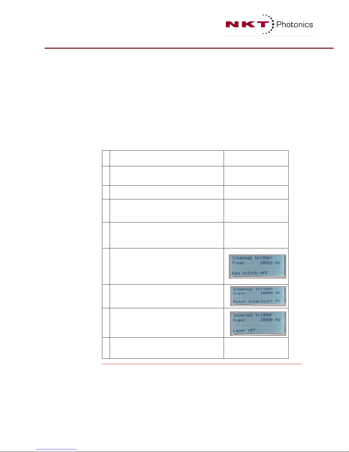
6
Turn on the Power by means of the main power
switch on the front panel.
The LED for “POWER” will turn ON (green) and
the display will show the message: “Key switch
off”.
7
Turn the key switch clockwise.
The display will show the message :
“Reset interlock : []“
8
Press the Return button [].
The display will show the message : “Laser off”.
The laser is now ready for operation.
9
Turn on emission by pressing the emission button.
The emission LED will turn on (Red). Light is
emitted from the laser.
Table 4.1: Step-by-step procedure for turning on the system.

P a g e | 14
The SuperK COMPACT may be operated in different modes. Table 4.2; 4.3; 4.4 and
4.5 describes the operating procedures for the different operating modes.
The laser can run with internal trigger mode. The resolution of the different modes
is dependent on the maximum frequency available and the hardware. If a more
precise setting of frequency/repetition rate is wanted, the laser must be run in
external trigger mode. To operate the laser using the internal trigger mode use the
following procedure:
1
Follow steps 1-8 in table 4.1.
The laser emission is off and the
display shows the message ‘laser off’.
2
Press enter to enter the system menu,
then select “operating mode”.
3
From the operating mode menu select
“internal trigger”.
4
From the operating mode menu select
“frequency” and set the frequency
using the selection wheel and enter
button.
5 Leave the system menu by pressing
the Return button [].
6
Turn on emission by pressing the
emission button. The emission LED will
turn on (Red). Light is emitted from
the laser.
7
To turn off emission press the
emission button.
8
It is also possible to change the
repition rate during emission.
Table 4.2: Operating in internal trigger mode.

P a g e | 15
Use the following procedure to operate the SuperK COMPACT using the external
trigger:
1
Check that the external trigger source delivers a trigger signal
between 0-4 volt with a frequency less or equal to the
maximum laser frequency.
2
Connect the external trigger source to the “COAX TRIG INPUT”
(see figure 8).
3
Follow steps 1-8 in table 4.1. The laser emission is off and the
display shows the message ‘laser off’.
4
Press enter to enter the system menu, then select “operating
mode”.
5
From the operating mode menu select “external trigger”.
6
From the system menu select “Coax trig level” and set the
trigger level.
7
Leave the system menu by pressing the Return button [].
8
Turn on emission by pressing the emission button. The
emission LED will turn on (Red). Light is emitted from the
laser.
Table 4.3: Operating in external trigger mode.
Use the following procedure to operate the SuperK COMPACT using the external
trigger burst mode:
1
Check that the external trigger source delivers a trigger signal
between 0-4 volt.
2
Connect the external trigger source to the “COAX TRIG INPUT”
(see figure 3.2).
3
Follow steps 1-8 in table 4.1. The laser emission is off and the
display shows the message ‘laser off’.
4
Press enter to enter the system menu, then select “operating
mode”.
5
From the operating mode menu select “external trigged burst”.
6
From the system menu select “Coax trig level” and set the
trigger level.
7
From the system menu select “Burst pulses” and set the
number of pulses.
8
From the operating mode menu select “frequency” and set the
frequency using the selection wheel and enter button.
9
Leave the system menu by pressing the Return button [].
10
Turn on emission by pressing the emission button. The
emission LED will turn on (Red). Light is emitted from the laser
when a trigger is delivered by the external trigger source.
Table 4.4: Operating in external trigger burst mode.

P a g e | 16
Use the following procedure to operate the SuperK COMPACT using the external
gate mode:
1
Check that the external trigger source supplies a trigger signal
between 0-4 volt.
2
Connect the external trigger source to the “COAX TRIG INPUT”
(see figure 8).
3
Follow steps 1-8 in table 4.1. The laser emission is off and the
display shows the message ‘laser off’.
4
Press enter to enter the system menu, then select “operating
mode”.
5
From the operating mode menu select “external gate on” or
“external gate off”
6
From the system menu select “Coax trig level” and set the
trigger level.
7
From the operating mode menu select “frequency” and set the
frequency using the selection wheel and enter button.
8
Leave the system menu by pressing the Return button []. The
display will show the selected frequency and number of pulses
in the burst.
9
Turn on emission by pressing the EMISSION button. The
emission LED will turn on (Red). Light is emitted from the laser
when the trigger level is high (low).
Table 4.5: Operating in external gate mode.
Please refer to section 6.1 for further information on the different operating
trigger modes like software burst mode etc.
Warning When operating at low repetition rate changing to a higher repetition rate a “Pulse
Overrun” situation may occur. E.g. changing from 1 kHz to 20 kHz could
momentarily trigger a “Pulse Overrun” situation due to the sudden change in pulse
acquisition. If this is observed, it is recommended to increase the repetition rate in
smaller steps of e.g. 5 kHz. In generally if a “Pulse Overrun” situation is encountered
it is recommended to turn down the repetition rate until the “Pulse Overrun” warning
disappears.
This can also happen in some variation of burst mode settings. We recommend to
lower the number of pulses or lower the rep rate.
Continuously “Pulse Overrun” warning in internal trigger mode will require service
from NKTP HQ.

P a g e | 17
4.3 SuperK COMPACT with FC output connector
Connector Handling and connecting the fiber output connector (FC/PC or FC/APC).
The FC/(A)PC connector is provided as a convenient means of terminating the fiber
and allowing the use of standard receptacles or holders to launch the light via free
space into other optical components/equipment.
Warning It is emphasized that if the SuperK connectorized fiber is mated to
another connectorized component, then there is an increased risk of
damage to the connector. This is because the SuperK COMPACT will
deliver significant peak power from the fiber and any loss, dirt or stress in
the connector due to mating, can promote damage.
The exit fiber and the connector is NOT covered by the warranty.
It is not guaranteed that this damage can be avoided, if connector mating is used,
but one can reduce the risk by adhering to the following:
Cleaning facet Before connecting the output, please ensure that the fiber facet is clean and free
of dust particles. A dirty fiber facet, may result in severe damage to the fiber facet
resulting in a significantly distorted beam profile. Dust from the fiber facet may be
removed be a number of approved fiber cleaning methods. Lens cleaning tissue
(lint free wipes) or similar appropriate material may be applied.
4.4 SuperK COMPACT with collimated output
The SuperK COMPACT can also be supplied with an armored fiber delivery,
terminated by a collimator, see figure below. The collimator consists of two
parts:
Collimator housing: outer diameter 28 mm
Collimator tube: outer diameter 12 mm
Figure 4.3: The optical output with collimator.
Warning
Do not open the collimator. This might destroy the entire laser system.
The warranty is void if the collimator is opened.
Warranty Sign
The output collimator is equipped with a “Warranty Void if removed” sign (figure
4-4). The sign indicates that the collimator should under no circumstances be
attempted to be taken apart. There are no serviceable parts inside the collimator.
Figure 4.4: Warranty Void sign on collimator

P a g e | 18
Beam Properties
The output beam is collimated with an achromatic lens to maximize coupling of
light into a single mode fiber. However, with a single lens it is impossible to
simultaneously maximize the coupling at all wavelengths of the output spectrum.
Per default the coupling is optimized for maximum average coupling across the
visible spectrum. Consequently, the beam is slightly larger for the infrared than
for the visible wavelengths; see table below for details.
Wavelength
Beam size at
collimator
Distance from collimator to where
beam has expanded to 1 cm
600 nm
Approx. 1 mm
Approx. 4 m
1500 nm
Approx. 3 mm
Approx. 6 m
Table 4.6 : Beam size after collimator for two wavelengths
Fixation of
collimator
During operation the collimator must be fixed for safety. For best performance,
we recommend the SuperK collimator holder (part no. A000-000-002) shown
below. If using other holders, we recommend gentle fixation on the collimator
tube using plastic screws instead of metal screws to minimize risk of scratches on
the collimator.
Figure 4.5: NKT Photonics collimator holder, part no. A000-000-002
Warnings
If the collimator is scratched it might not fit into the collimator input in
the SuperK accessories.
A small fraction of the beam power is absorbed in the collimator by stray light. If
the thermal contact between the collimator and the surroundings is poor, the
collimator can become significantly warmer than the surroundings. Thus, it is
recommended to enable firm thermal contact between the collimator and the
surroundings.

P a g e | 19
Section
5:
Display
messages
5.1 Warning and error messages
Before and during operation, the SuperK COMPACT laser will show various
messages in the display. Some of these indicate errors or other circumstances
that prevent the unit from functioning - others are merely information to the
operator. The warnings, alarms and messages are explained below.
Messages
Message
Description
Emission
Emission is on. Emission LED activated (red).
Laser off
Emission is off. Emission LED off.
Door interlock
Emission is not possible, because the
external interlock loop is open. Check the
external interlock loop connected by the
LEMO connector at the interlock socket (see
Figure 3.2).
External interlock
Emission is not possible, because the
external interlock loop through the external
bus port is open.
Check the Bus Termination.
If an Accessory is connected to the bus, it
can be an opening in the interlock circuit on
the Accessory.
Check the external bus interlock loop.
Key switch off
Emission is not possible, because the key
switch is set to ‘OFF’.
Interlock opened
while emission is on
Emission stopped, because the interlock
opened while emission is on. This can be
caused be either of the above.
Table 5.1: List of common display messages

P a g e | 20
Section
6:
Trigger input and remote connection
6.1 Trigger operating modes
The selected operating mode determines when and how often the light source
generates an optical pulse. The operating mode can be selected in the front panel
menu or via the USB/RS-232 port.
Most operating modes use some additional settings: Frequency (repetition rate)
and/or Burst count. These can be altered in the front panel menu or via the
USB/RS-232 interface.
Internal trigger
The light source emits pulses at the user selected repetition rate. The resolution of
the different modes is dependent on the maximum frequency available and the
hardware. Trigger inputs are not used.
External trigger
One of the trigger inputs are used for triggering optical pulses. One optical pulse
is generated for each electrical trig pulse.
Software burst
The light source emits a specified number of pulses (Burst count) at the specified
repetition rate only when ordered to do so by an external host via the USB or RS232 interface.
Externally trigged burst
When the light source senses a positive edge on one of the trig inputs, the light
source emits a specified number of pulses (Burst count) at the specified repetition
rate.
External gate on
When one of the trig inputs receives a logic "high" signal, the light source emits
pulses continuously at the specified repetition rate, until the trig signal goes low.
The light source may emit one extra pulse after the trig signal has gone low.
External gate off
When both of the trigger inputs receives a logic "low" signal, the light source
emits pulses continuously at the specified repetition rate, until one trigger signal
goes high. The light source may emit one extra pulse after the trig signal has
gone high.
Note:
Although most of the operating modes can be used to keep pulses from being
generated, the light source must still be regarded as having emission on. Stopping
pulses by using the trig signals in a certain way, is not considered a safe way to keep
emission off.

P a g e | 21
6.2 Remote interface connection
Remote connection A USB and an RS-232 interface is located on the backside of the SuperK
COMPACT unit for communication with the unit through a computer.
The serial communications port on the SuperK COMPACT is a standard USB port,
designed for connecting to a standard PC USB-port. In order to connect the
SuperK COMPACT to a computer for remote operation please use a standard USB
cable with A to B connectors as indicated in figure 6.1. For RS-232 operation use
a D-Sub9 connector with standard RS232 pin out.
Figure 6.1: USB Cable A to B
SuperK CONTROL If you are interested in communicating with the laser system using as computer,
we recommend the NKT Photonics CONTROL software. CONTROL is compatible
with all latest generation NKT Photonics lasers and accessories. The software can
be located on our webpage for download.
SDK If you are interested in communicating with the laser system using the remote
interface, a special software development kit (SDK) is available. The software can
be located on our webpage for download.
6.3 External Trigger input
External trigger The trigger inputs are used for all modes except the Internal Trigger and Software
Burst modes. The function of the trigger signal depends on the mode that is used.
In order to accommodate most applications, there are two different kinds of
inputs. The operator selects which input to use by applying a trig signal to one
input, and nothing to the other. Signal is trigged on rising edge.
Warning Do not attempt to trigger with a signal above 200 kHz as this may slow down
performance of the SuperK COMPACT due to firmware limitations. The output
repetition rate will also be limited by the maximum repetition rate of the system.
6.4 Coax trigger input
Analogue input The coax trig input is a logic input with a 50 Ω impedance. The actual trig level
(the voltage level at which the light source is trigged) is adjustable from the front
panel menu (or the SuperK CONTROL), from 0 to +4 V. There is a hysteresis of
approximately 1 %, to reduce noise sensitivity.
Input impedance: Nom. 50 Ω
Input voltage (peak): Min. −7 V; max. 7 V
Input power (RMS): Max. 0.8 W / 29 dBm

P a g e | 22
Pulse width: Min. 200 ns
Trig level (adjustable): Min. 0 V; max. 4 V
Hysteresis: Approx. 1 %
Connector type: BNC
Max trigger frequency: 200 kHz
6.5 Industrial trigger input
This input is isolated electrically from the light source, which allows the operator
to connect the input to a wide variety of equipment. The input voltage range is
high, and the input impedance is considerably higher than the coax trig input
impedance. However, this input is not as fast as the coax trig input. The trig
voltage level is fixed (not adjustable).
Minimum pulse width: 5 µs
Max. input voltage (RMS): ± 30 V
"On" signal threshold (max): + 3.9 V
"Off" signal threshold (min): + 1.18 V
Input impedance @ 5 V: ≈ 1.7 kΩ
Input impedance @ 24 V: ≈ 1.45 kΩ
Isolation voltage: 350 V
Connector type: 5.08 mm terminal connector
6.6 Logic and analogue pulse output
Two types of output trigger are available: an analogue trigger output signal and a
logic trigger output signal.
Analogue output The analog pulse output is an amplified representation of the optical signal, while
the logic pulse is a digital representation of the analogue signal generated
subsequently. This may be used for detection of optical pulses, with minimum
timing jitter, i.e. for timing critical purposes.
Pulse width: ≈ 10 ns
Pulse voltage: System dependant (max. 2 V)
Output impedance: 50 Ω
Connector type: BNC
Logic output The logic pulse output generates a positive logic signal whenever the light source
emits an optical pulse. This can be used for triggering and pulse counting.
Pulse width (min): 1 µs
Pulse voltage (nom): ≈ 2.5 V @ 50 Ω load
Low-level output voltage (nom): 0 V
Output impedance: 50 Ω
Connector type: BNC

P a g e | 23
Section
7: Service & Support
7.1
Service and storage
General service There are no user serviceable components inside the SuperK. In case of malfunction,
NKT Photonics should be consulted.
The unit is sealed with a label “WARRANTY VOID IF
REMOVED”. There is a
potential risk of damage to the unit and/or personnel if this is compromised. It is
therefore strictly prohibited to remove the chassis cover.
A SuperK COMPACT should be returned to NKTP for service in its original casing
or similar. When in doubt, contact Technical Support prior to packaging.
Cleaning of t h e
Chassis
If cleaning of the SuperK unit is required the chassis may be cleaned with a damp
cloth. Do not use solvents for cleaning the chassis.
Storage If required the SuperK COMPACT should be stored in a dry and cool place. The
optical output should be protected using supplied caps. Avoid exposing the unit
to any vibrations or mechanical shocks.
7.2 Fiber tip cleaning
Fiber tip
cleaning
Only use cleaning tools that are specifically designed to be used with optical fibers.
Always use extreme caution when cleaning fibers.
Examples of appropriate cleaning tools are lens cleaning tissue (lint free wipes) as
shown in figure 7.1 or an Optical Fiber Cleaning Tool as shown in figure 7.2.
Figure 7.1: Lens cleaning tissue (lint free wipes).
Figure 7.2: Example of an Optical Fiber Cleaning Tool.
Signs of damage Signs of a damaged fiber facet may be one of the following:
Power suddenly decreases (from e.g. 100 mW to 60-70 mW)
The spectrum (as recorded from an Optical Spectrum Analyzer) is

P a g e | 24
significantly degraded compared to the original spectrum found in the
measurement report.
Light from the facet is not emitted in the usually hexagonal pattern but
rather in a random pattern with a large variation in colors (see Figure
7.3).
Figure 7.3: Left: Correct beam profile. The emitted beam has a noticeable hexagonal shape.
Right: Incorrect beam profile as a result of a damaged fiber facet. Emitted beam is random
in direction and colors.
If the fiber facet is damaged the connector must be re-polished before operation of
the SuperK COMPACT can continue. Failing to do so could result in incorrect
measurements/usage or even damage to the laser unit itself.
Warning Please note that the fiber from the SuperK COMPACT is a Photonic
Crystal Fiber
(PCF). Thus the connector should NOT be removed, as
special equipment and procedures are required to mount a new
connector onto the fiber.
Polishing The end of the fiber is collapsed at a length of 150-200 micron. Thus, there is
room to polish the fiber end, but one has to be careful not to over polish and we
recommend to send the unit for repair to do this. The procedure is:
1) Clean the connector and carefully polish the connector end shortly.
2) Clean the connector and then switch the source on. Observe the exit beam on a
screen. If it is not a nice single mode emission, re-polish another short time.
3) Continue this "quick polish, check beam" process until a nice beam is
obtained.
If one does not obtain a nice beam regardless, then the connector might be
damaged. In this case, the unit should be returned to NKT Photonics for repair.
Please note that this type of repair is not covered by warranty.
7.3 Technical s
upport
NKT Photonics can be contacted for technical information regarding issues with use
of the SuperK COMPACT or associated accessories.
Contact information:
NKT Photonics A/S
Blokken 84
DK-3460 Birkerød, Denmark
Phone (general): +45 4348 3900
Fax (general): +45 4348 3901
E-mail: mailto:support@nktphotonics.com

P a g e | 25
Section 8
:
Specifications
of the
SuperK
COMPACT
8.1 Electro-mechanical Specifications
Environmental
Temperature, operating
15-30 °C
Temperature, storage, non condensing
5-50 °C
Humidity, non condensing
20-80 % RH
Power
Power consumption, nominal with no accessories
connected
40 W
Power consumption, maximum
150 W
Line
100 – 240 VAC
Frequency
50-60 Hz
Fuses (5 × 20 mm)
Type: T 2A, 250 V
Weight
3,5 kg
Table 8.1: Electro-mechanical specifications
8.2 Optical Specifications
Min. Total Output Power
> 110 mW
Min. Visible Output Power (450-850 nm)
> 25 mW
Wavelength range
450 – 2400 nm
Spectral Stability (600-1040 nm)
< 0.12 db/hr
Spectral Stability (1100-1500 nm)
< 0.14 dB/hr
Max. Repetition rate
> 20 kHz
Output Pulse Length
< 2 ns
Length of out fiber cable
1.6 ± 0.1 m
Table 8.2: Optical specifications

P a g e | 26
8.3 System dimensions
Dimensions: All dimensions in mm

Section 9: Accessories for the SuperK COMPACT
SuperK SPLIT allows the SuperK spectrum to be divided into two spectral outputs.
In its standard form, the SuperK SPLIT provides two outputs: Visible and nIR.
However, the choice of the split in the spectrum can be user-defined to be
anywhere in the SuperK spectrum. Additionally, standard mounts within the SPLIT
allow the insertion of narrow band filters, polarisers or attenuators at each output
exit for further flexibility.
SuperK CONNECT is a high performance fiber delivery system complete with
broadband fibers and a range of termination options such as FC/PC connectors or
collimators. Interfacing is handled by the CONNECT fiber coupling unit that ensure
easy and stable single-mode coupling that can be disconnected and reconnected
without alignment.
SuperK VARIA is a cost effective and flexible alternative to a monochromator,
effectively turning the SuperK into a powerful single-line laser with a 440 nm
tuning range and variable bandwidth. The center wavelength of the pass band can
be tuned between 400 and 840 nm and the bandwidth is variable between 10 and
100 nm, making the VARIA the most flexible filter solution on the market.
Increasing the bandwidth of the filter increases power throughput and reduces
speckle in imaging applications. Moreover, a high out-of-band suppression of 50dB
makes the SuperK VARIA ideal for FLIM and other applications using high
sensitivity detectors.
SuperK SELECT is a tunable wavelength filter based on acusto-optic tunable filter
technology (AOTF). AOTFs tune over one octave of optical frequency and the
SuperK SELECT allows the integration of two AOTF crystals to provide wide
spectral coverage. Together with a range of unique features, the SuperK SELECT
provides an easy to use, flexible and accurate tuning accessory to access any
wavelength in the SuperK spectrum.
LLTF Tunable High Contrast Filter is a continuously tunable high-resolution
bandpass filter that effectively converts a NKT Photonics’s supercontinuum source
into a widely tunable picosecond laser. The filter transmits, with high efficiency, a
single laser line while blocking unwanted lines with excellent out-of-band
suppression.
The SuperK EXTEND-UV is a deep-UV supercontinuum spectral extension unit for
our SuperK EXTREME and COMPACT supercontinuum lasers. Get tunable UV light
from a robust fiber laser source with 270-480 nm range and 2-80 µW output
power.

P a g e | 28
User Notes

NKT Photonics
Blokken 84
3460 Birkerød
Denmark
Phone: +45 43483900
Fax: +45 43483901
www.nktphotonics.com
 Loading...