

IS-Dev Kit-8 User Manual
7850 East Gelding Drive • Scottsdale, AZ 85260-3420
IS-Dev Kit-8 User Manual
Revision A
IS-Dev Kit-8 Version 1.0
NKK SWITCHES
7850 E. Gelding Drive
Scottsdale, AZ 85260
Toll Free 1-877-2BUYNKK (877-228-9655)
Phone 480-991-0942
Fax 480-998-1435
e-mail <engineering@nkkswitches.com>
All Rights Reserved Worldwide
NKK Switches makes no warranty for the use of these products and assumes no responsibility for any errors,
which may appear in this document, nor does it make a commitment to update the information contained herein.
Smart Switch is trademark of NKK Switches.
IS-Dev Kit 8 Users Manual A.doc
Toll Free 1.877.2BUYNKK (877.228.9655) • Phone 480.991.0942 • Fax 480.998.1435
www.nkkswitches.com • Email engineering@nkkswitches.com 1209
Page 1 of 31

IS-Dev Kit-8 User Manual
7850 East Gelding Drive • Scottsdale, AZ 85260-3420
TABLE OF CONTENTS
Table of Contents.............................................................................................................2
1. General Controller Features.........................................................................................3
2. Thank you for purchasing NKK Switches’ IS-Dev Kit-8............................................4
3. Preface..........................................................................................................................5
4. Operational Overview..................................................................................................6
5. Programming the IS-Dev Kit-8....................................................................................8
6. Communication Protocol .............................................................................................14
7. Commands ...................................................................................................................15
8. Hardware......................................................................................................................23
9. Key Terms & Definitions.............................................................................................24
10. Firmware problems ....................................................................................................26
A. Appendix.....................................................................................................................27
IS-Dev Kit 8 Users Manual A.doc
Toll Free 1.877.2BUYNKK (877.228.9655) • Phone 480.991.0942 • Fax 480.998.1435
www.nkkswitches.com • Email engineering@nkkswitches.com 1209
Page 2 of 31

IS-Dev Kit-8 User Manual
7850 East Gelding Drive • Scottsdale, AZ 85260-3420
1. General Features
The IS-Dev Kit-8 Version 1.1 controls one monochromatic OLED Rocker with a resolution of 96x64 pixels.
Below are current features:
• Controls one OLED Rocker.
1. Three button rocker; top, middle, and bottom.
2. White monochrome OLED display with a resolution of 96x64 pixels.
3. IP64 dust protected & splashproof.
4. Snap-in mount.
• On board selection between 9V battery and AC power supply.
• On board microSD Flash that can hold up to 65,536 images.
• Adjustable audio feedback when a switch is pressed.
• 16 level of brightness settings to extend OLED life.
• User programmable for images, attributes and set-ups.
• Stand alone operation or real-time control by host.
1. Available command to direct the controller to display images in real-time.
2. Programmable to change the displayed image based on a switch actuation and user defined
timers for stand alone operation.
• Serial communication via RS232 (57.6K, 1 start bit, 8 bit, 1 stop bit).
• Reports switch activity and timer expiration via serial port.
• Set the type of activity reports from the controller to host.
• Controller board firmware can be customized based on customer requirements.
IS-Dev Kit 8 Users Manual A.doc
Toll Free 1.877.2BUYNKK (877.228.9655) • Phone 480.991.0942 • Fax 480.998.1435
www.nkkswitches.com • Email engineering@nkkswitches.com 1209
Page 3 of 31

IS-Dev Kit-8 User Manual
7850 East Gelding Drive • Scottsdale, AZ 85260-3420
2. Thank you for purchasing NKK Switches’ IS-Dev Kit-8
By purchasing this kit a new horizon of design is expanding before your eyes. The OLED Rocker can be the
distinguishing feature within your application that sets your product apart from the competition. This kit
contains all the necessary components to get you started using, testing and ultimately incorporating NKK
Switches’ OLED Rocker into your designs.
At NKK Switches’ SmartSwitch web site, http://www.nkksmartswitch.com/, free software, Universal
Communicator, is available for downloading both images and attributes to the Dev Kit-8.
This kit includes:
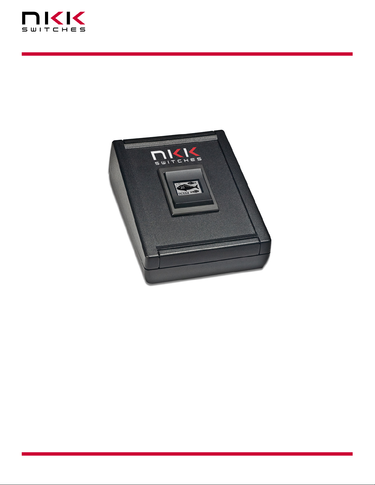
• Display unit with OLED Rocker and control board. (instruction card included)
• Serial port to RS232 adapter cable.
• Power supply.
IS-Dev Kit-8
IS-Dev Kit 8 Users Manual A.doc
Toll Free 1.877.2BUYNKK (877.228.9655) • Phone 480.991.0942 • Fax 480.998.1435
www.nkkswitches.com • Email engineering@nkkswitches.com 1209
Page 4 of 31

IS-Dev Kit-8 User Manual
7850 East Gelding Drive • Scottsdale, AZ 85260-3420
3. Preface
The IS-Dev Kit-8 is a development kit designed to demonstrate the features of the SmartSwitch OLED rocker
as well as facilitate the incorporation of the rocker into new application designs. The OLED Rocker is best used
for displaying and navigating through a menu or for setting a level or a quantity.
This user manual will go through general features and rudimentary commands, like how to download images
and attributes, and then go into the more technical details of how the Dev Kit-8 operates.
Section 4 and 5 briefly describe the basic Dev Kit operations and provide a starter guide for programming the
Dev Kit with the most popular commands using the Universal Communicator program. These sections were
designed for those who wish to simply start using the Dev Kit without getting into the technical details.
Section 6, 7, and 8 covers communication and commands between the host computer and the Dev Kit
controller. Section 9 is the hardware and the schematic and section 10 and 11 are definitions and firmware
issues. There is also an appendix for understanding hexadecimal.
Universal Communicator
Universal Communicator version 1.4.2, and up is a free program provided by NKK Switches to help download
images and attributes to the Dev Kit controllers. It is available at engineering@nkkswitches.com or at NKK
Switches’ SmartSwitch web site, http://www.nkksmartswitch.com/. The program is designed to work with the
family of SmartSwitch Dev Kits. It can import bitmaps, convert them to the proper switch format, and then
download them to the controller. It can also handle attribute downloads. It can handle single or batch downloads
and has the most common commands as easy button interfaces. On the NKK SmartSwitch website documents
can be found for creating images as well as the manual for Universal Communicator that shows how to
download images and attributes. They can be found at: http://www.nkksmartswitch.com/support/docs.asp.
IS-Dev Kit 8 Users Manual A.doc
Toll Free 1.877.2BUYNKK (877.228.9655) • Phone 480.991.0942 • Fax 480.998.1435
www.nkkswitches.com • Email engineering@nkkswitches.com 1209
Page 5 of 31

IS-Dev Kit-8 User Manual
7850 East Gelding Drive • Scottsdale, AZ 85260-3420
4. Operational Overview
Power-up and Brightness Adjustment:
When the power is turned on, the OLED displays the image below and allows for brightness adjustment.
There are 16 level of brightness 0,1,2,3,4,5,6,7,8,9,A,B,C,D,E and F where F is the maximum brightness. The
level of brightness is displayed in the middle of image. After power up, the display is at the maximum
brightness level (F). Pressing the bottom switch will make the display dimmer. Pressing the top switch will
make the display brighter. The OLED rated life of 52,000 hours is based on the maximum brightness. The
dimmer the level is set the longer the life of the OLED. Any switch activity will keep the unit in this mode.
After 2.6 seconds of user inactivity the controller will move into the main operations mode.
Main Operational Mode
The IS-DEV KIT-8 is programmed with factory default images. The user can change the images and
programming through the use of attributes. The images are pictures to be displayed. The attributes are user
defined information on what image to display based on the switch activity and when the timer expires. After the
brightness adjustment mode the OLED Rocker displays the image at address 1 and uses the attribute
information of address 1. There is room for 65,535 images and attributes (address 1 to 65535) in memory.
The controller associates one address to each image and the display shows the image at the associated address.
Each address has a group of seven attributes which together is called an Attribute Block. The function of the
Attribute Block is to tell the controller what image to display next either when the switch associated with that
particular address is pressed or when the timer expires. These are called actions.
IS-Dev Kit 8 Users Manual A.doc
Toll Free 1.877.2BUYNKK (877.228.9655) • Phone 480.991.0942 • Fax 480.998.1435
www.nkkswitches.com • Email engineering@nkkswitches.com 1209
Page 6 of 31

IS-Dev Kit-8 User Manual
7850 East Gelding Drive • Scottsdale, AZ 85260-3420
For visual illustration, through out the document blue is used to show a top switch action, green is a middle
switch action, a red is the bottom switch action, and a dotted violet line is the timer action.
Illustration 1, Switch and timer actions as described by the attributes.
The Hex number shown is the address of an image that is displayed.
Attribute Information (Attribute Block)
There are seven attributes per image.
1. Top Switch Address. The address of the image to be displayed if the top switch is pressed.
When the top switch is pressed:
A. If the address is set to zero there will be no change.
B. If the address is set to a positive number the image at the address is displayed and the
attributes at the address become active.
2. Middle Switch Address. The address of the image to be displayed if the middle switch is pressed.
When the middle switch is pressed:
A. If the address is set to zero there will be no change.
B. If the address is set to a positive number the image at the address is displayed and the
attributes at the address become active.
3. Bottom Switch Address. The address of the image to be displayed if the bottom switch is pressed.
When the bottom switch is pressed:
A. If the address is set to zero there will be no change.
B. If the address is set to a positive number the image at the address is displayed and the
attributes at the address become active.
4. End Address. The address of the last image to be displayed in an image sequence starting at the
current address and ending at the end address where the speed of the sequence is based on the timer
value.
A. If the timer is set to zero this is attribute is ignored.
IS-Dev Kit 8 Users Manual A.doc
Toll Free 1.877.2BUYNKK (877.228.9655) • Phone 480.991.0942 • Fax 480.998.1435
www.nkkswitches.com • Email engineering@nkkswitches.com 1209
Page 7 of 31

IS-Dev Kit-8 User Manual
7850 East Gelding Drive • Scottsdale, AZ 85260-3420
5. Timer. The timer controls how fast to cycle through displaying the images sequentially. The timer
can be up to 65 seconds. The images change sequentially from the beginning address (the active
attribute address) to the end address (4)
A. If the timer is set to zero there will be no changes based on the timer.
B. If the timer is set to a positive number the timer starts running. If any of the switches are
pressed, the timer gets reset. If a switch press causes a new image to be displayed the
attributes associated with the new image become active.
When the timer expires:
For each timer expire:
- If the address of the image displayed is not equal to the End address (4):
i. Then the next image is displayed. (The Attribute Block of the new image is
ignored.)
ii. And the timer is reset and starts running again.
- If the address of the image being displayed is equal to the End address (4) then the
Middle address (2) of the End address (4) attribute block is checked.
i. If the Middle address (2) is zero the image from the beginning address is
displayed. This will create a loop of the images from beginning address to end
address to be displayed until the a switch press causes a change
ii. If the Middle address (2) is a positive number the image at the address is
displayed and the attributes at the address become active.
6 & 7 Reserved for future use and must be set to zero.
5. Programming the IS-Dev Kit-8
The IS-Dev Kit-8 communicates via RS232 with any communication software. The commands and protocol
will be explained in the sections 6 and 7.
This section covers programming the Dev Kit using the Universal Communicator.
The Universal Communicator handles all the communication protocol. Once the images are created, they can be
imported to the universal Communicator. The universal communicator allows attributes information to be
inputted. Once the images and attribute information are created, they can be downloaded to the Dev Kit. The
Dev Kit will function as programmed after the next power up or reset.
For how to use the software please refer to Universal Communicator documentation.
Creating OLED Rocker Images for Universal Communicator
The OLED Rocker display is 96x64 pixel monochrome. Images can be created graphically or by cropping from
a picture using graphic software such as Paint, Photoshop, etc. The images must be saved as 96x64
monochromatic bitmap files. The image files should be saved in a single folder. Universal Communicator
imports the files from the folder in alphanumeric order according to the file names. The file names should be
selected so the order of images will be as desired.
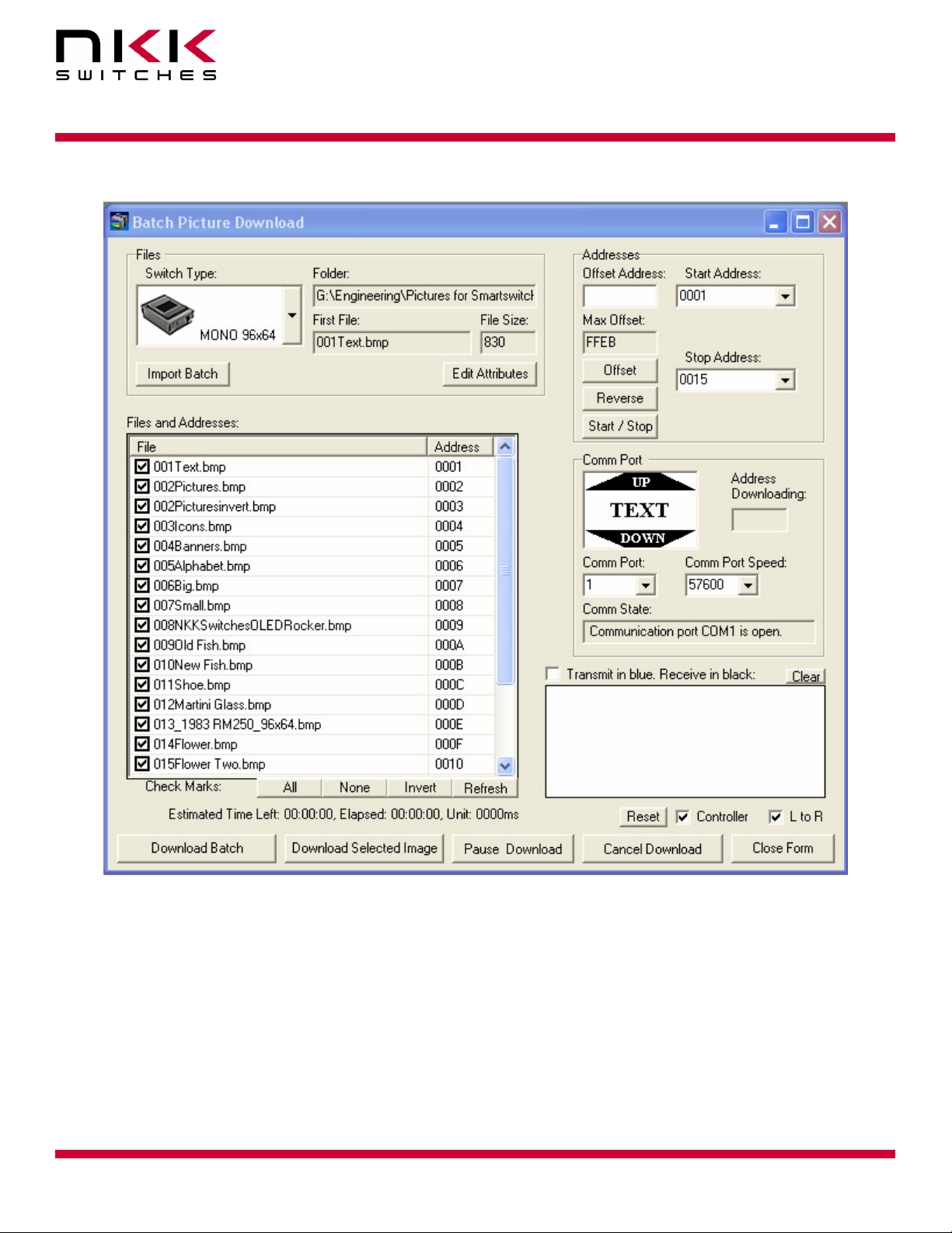
The Universal Communicator displays the image file names and assigned addresses for the controller. (Screen
shot 1)
These files can be downloaded to the controller.
IS-Dev Kit 8 Users Manual A.doc
Toll Free 1.877.2BUYNKK (877.228.9655) • Phone 480.991.0942 • Fax 480.998.1435
www.nkkswitches.com • Email engineering@nkkswitches.com 1209
Page 8 of 31
IS-Dev Kit-8 User Manual
7850 East Gelding Drive • Scottsdale, AZ 85260-3420
Screen Shot 1, Universal Communicator Batch Picture Download Window
Input/programming the Attribute information
After importing the images into the Universal Communicator (Screen shot 1), Make sure the order of the images
are as desired so all the loops for sequential changes based on timer are sequential.
You can select “Edit Attributes” from Batch Picture Download screen (Screen shot 1).Universal Communicator
display “Batch Attributes Download screen and allows input of the attributes information. (Screen shot 1)
All the numeric inputs only allow HEX format. The addresses are four digit long HEX values from 0001H to
FFFFH (1 to 65,535 decimal). The Universal Communicator lists the addresses in HEX format. These
addresses can be used for attribute information without knowing HEX numbering. For HEX numbering and
conversion between HEX and decimal please refer to the appendix.
IS-Dev Kit 8 Users Manual A.doc
Toll Free 1.877.2BUYNKK (877.228.9655) • Phone 480.991.0942 • Fax 480.998.1435
www.nkkswitches.com • Email engineering@nkkswitches.com 1209
Page 9 of 31
IS-Dev Kit-8 User Manual
7850 East Gelding Drive • Scottsdale, AZ 85260-3420
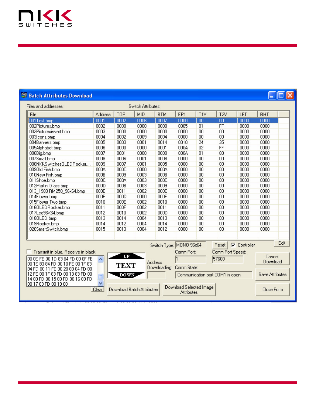
The image name and the address as well as attribute information are displayed. There are two additional
information inputs which are reserved and should be 0000. The attribute information can be modified by the
user.
Screen Shot 2, Universal Communicator Batch Attribute Download Window
Timer
The timer controls the number of milliseconds to display an image before switching to the next in the sequence.
The timer consists of two numbers called Timer1 and Timer2. Each timer is a two digit hex number between
00H and FFH (1 to 255 decimal). If Timer1 is set to zero the timer does not run. If Timer2 is set to 0 it will
count as 256.
The amount of time in millisecond = (Timer1) x (Timer2)
The maximum timer is when the Timer1 = FFH and Timer2 = 00H :
The maximum timer value = 255x256= 65280 ms = 65.28 Seconds.
IS-Dev Kit 8 Users Manual A.doc
Toll Free 1.877.2BUYNKK (877.228.9655) • Phone 480.991.0942 • Fax 480.998.1435
www.nkkswitches.com • Email engineering@nkkswitches.com 1209
Page 10 of 31

IS-Dev Kit-8 User Manual
7850 East Gelding Drive • Scottsdale, AZ 85260-3420
The timer for 25 frame/s video is 40 ms so some possible Timer1 and Timer2 values can be as followed:
Timer1 = 01H and Timer2= 28H or Timer1=05H and Timer2=08H.
For HEX numbering and conversion between HEX and decimal please refer to the appendix.
An Example of How Attributes Work
The following demonstrate the way attributes of Screen shot 2 (above) works. The Illustration 2 (below)
visually demonstrates the way these attributes work.
The blue is the top switch action, the green is the middle switch action, the red is the bottom switch action, and
the dotted violet line is the timer action.
Illustration 2, Examples of various loops
Illustration only shows switch and timer actions that result in an image change on the
display. All other attributes are ignored by the controller and are not shown.
When the Dev Kit enters the Main Operational Mode the image at the address 0001H is displayed. The
Attribute Block at address 0001H becomes active.
IS-Dev Kit 8 Users Manual A.doc
Toll Free 1.877.2BUYNKK (877.228.9655) • Phone 480.991.0942 • Fax 480.998.1435
www.nkkswitches.com • Email engineering@nkkswitches.com 1209
Page 11 of 31
IS-Dev Kit-8 User Manual
7850 East Gelding Drive • Scottsdale, AZ 85260-3420
Attribute Block at address 0001H
Top
Current
Address
0001H 0002H 0006H 0007H 0000H 00H 00H
Since the Timer1 is zero the timer does not run so there will be no changes based on the timer.
The image at the address 0001H is displayed until any of the switches are pressed:
Pressing the Top Switch
Attribute Block at address 0001H
Current
Address
0001H 0002H 0006H 0007H 0000H 00H 00H
If the top switch is pressed, the image at address 0002H is displayed and the Attribute Block of address 0002H
becomes active.
Attribute Block at address 0002H
Current
Address
0002H 0000H 0000H 0000H 0005H 01H FFH
Since all the switch addresses are zero there will be no changes if a switch gets pressed. The timer is 255ms. If
there is no switch activity for 255ms the timer expires causing the next image, 0003H, to be displayed. This
continues until images 0004H and 0005H are also displayed. When the timer expires at address 0005H the
address is equal to the End Address. The Middle Switch Address from the Attribute Block of 0005H is then
checked. Please note the attribute information of addresses 0003H and 0004H are not used.
Attribute Block at address 0005H
Current
Address
0005H 0002H 0001H 0014H 0010H 24H 35H
The image at address 0001H is displayed and the Attribute Block of address 0001H becomes active. Notice that
the other attributes within the Attribute Block of address 0005H are ignored.
Switch
Address
Top
Switch
Address
Top
Switch
Address
Top
Switch
Address
Middle
Switch
Address
Middle
Switch
Address
Middle
Switch
Address
Middle
Switch
Address
Bottom
Switch
Address
Bottom
Switch
Address
Bottom
Switch
Address
Bottom
Switch
Address
End
Address Timer1 Timer2
End
Address Timer1 Timer2
End
Address
End
Address Timer1 Timer2
Timer1 Timer2
IS-Dev Kit 8 Users Manual A.doc
Toll Free 1.877.2BUYNKK (877.228.9655) • Phone 480.991.0942 • Fax 480.998.1435
www.nkkswitches.com • Email engineering@nkkswitches.com 1209
Page 12 of 31

IS-Dev Kit-8 User Manual
7850 East Gelding Drive • Scottsdale, AZ 85260-3420
Pressing the Middle Switch
Attribute Block at address 0001H
Top
Current
Address
0001H 0002H 0006H 0007H 0000H 00H 00H
If the middle switch, the image at the address 0006H is displayed and the Attribute Block of the address 0006H
becomes active.
Attribute Block at address 0006H
Current
Address
0006H 0000H 0000H 0001H 000AH 02H FFH
The timer is 510ms. If there is no switch activity for 510ms the timer expires causing the next image, 0007H, to
be displayed. This continues until images 0008H, 0009H, and 000AH are also displayed. When the timer
expires at address 000AH the address is equal to the End Address. The Middle Switch Address from the
Attribute Block of 000AH is then checked.
Attribute Block at address 000AH
Current
Address
000AH 000CH 0000H 000AH 0000H 00H 00H
Since the Middle Switch Address is zero then the image at address 0006H is displayed and the Attribute Block
of address 0006H stay active.
If the bottom switch is pressed in any address from 0006H to 000AH then the image at address 0001H is
displayed and the Attribute Block of address 0001H become active.
Pressing the Bottom Switch
Switch
Address
Top
Switch
Address
Top
Switch
Address
Middle
Switch
Address
Middle
Switch
Address
Middle
Switch
Address
Bottom
Switch
Address
Bottom
Switch
Address
Bottom
Switch
Address
End
Address Timer1 Timer2
End
Address Timer1 Timer2
End
Address
Timer1 Timer2
Attribute Block at address 0001H
Top
Current
Address
0001H 0002H 0006H 0007H 0000H 00H 00H
If the bottom switch is pressed, the image at the address 0007H is displayed and the Attribute Block of the
address 0007H becomes active.
Switch
Address
Middle
Switch
Address
Bottom
Switch
Address
End
Address Timer1 Timer2
IS-Dev Kit 8 Users Manual A.doc
Toll Free 1.877.2BUYNKK (877.228.9655) • Phone 480.991.0942 • Fax 480.998.1435
www.nkkswitches.com • Email engineering@nkkswitches.com 1209
Page 13 of 31

IS-Dev Kit-8 User Manual
7850 East Gelding Drive • Scottsdale, AZ 85260-3420
Attribute Block at address 0007H
Top
Current
Address
0007H 0001H 0000H 0000H 000AH 01H 80H
The timer is 128ms. If there is no switch activity for 128ms the timer expires causing the next image, 0008H, to
be displayed. This continues until images 0009H and 000AH are also displayed. When the timer expires at
address 000AH the address is equal to the End Address. The Middle Switch Address from the Attribute Block
of 000AH is then checked.
Attribute Block at address 000AH
Current
Address
000AH 000CH 0000H 000AH 0000H 00H 00H
Since the Middle Switch Address is zero then the image at address 0007H is displayed and the Attribute Block
of address 0007H becomes active.
If the top switch is pressed in any address from 0007H to 000AH then the image at address 0001H is displayed
and the Attribute Block of address 0001H become active. Notice that the other attributes within the Attribute
Block are ignored. Notice that the loop starting at address 0007H overlaps the loop starting at address 0006H
and both end at the same End Address without interfering with each other.
Please note when the timer causes a new image to be displayed the Attribute Block of the beginning
image stays active. All other Attribute Blocks within the loop are ignored except the Middle Switch
Address of the End Address.
Switch
Address
Top
Switch
Address
Middle
Switch
Address
Middle
Switch
Address
Bottom
Switch
Address
Bottom
Switch
Address
End
Address Timer1 Timer2
End
Address Timer1 Timer2
6. Communication Protocol
Communication initiated by Host
The controller communicates with the host via RS232 serial communication (57.6K, 1 start bit, 8 bit, 1 stop
bit). The controller receives the data via an interrupt routine that places the data on the circular receive buffer.
When the controller detects data in the circular receive buffer, the controller reads one byte and executes the
following:
A. If the byte is a command, the controller transmits a 61H and executes the subroutine for the command
and upon completion of command the controller transmits 79H.
B. If the byte is not a command, it is ignored.
When the controller executes a subroutine and expects additional information:
IS-Dev Kit 8 Users Manual A.doc
Toll Free 1.877.2BUYNKK (877.228.9655) • Phone 480.991.0942 • Fax 480.998.1435
www.nkkswitches.com • Email engineering@nkkswitches.com 1209
Page 14 of 31

IS-Dev Kit-8 User Manual
7850 East Gelding Drive • Scottsdale, AZ 85260-3420
A. A timer is set. If the expected data byte is not received in 64ms, the controller transmits 6CH 6EH and
terminates the routine.
B. If the byte value is not acceptable (invalid range, option, etc.), the controller transmits 6EH and
terminates the routine.
Commands are one byte in the range of 20H to 2FH and 01H and are transmitted in hex format. The proper
format for all command options and data is specified for each command. See Section 7.
Communication initiated by the IS-Dev Kit-8
The Dev Kit transmits codes to host via RS232 based on activities stated below. Many of these reporting can
be enable/disabled by the flag setup.
A. Top switch press is reported as 91H
B. Top switch Release is reported as C1H
C. Middle switch press is reported as 92H
D. Middle switch Release is reported as C2H
E. Bottom switch press is reported as 93H
F. Bottom switch Release is reported as C3H
G. Timer Expire is reported as 94H
H. Upon changing the image, the image address is reported as FCH followed by the address in HEX so
total of 3 bytes transmitted for each image change.
I. If there is a communication problem between microcontroller and the microSD flash, the controller
will transmit 6FH to host for each communication failure.
7. Commands
Command to reboot the controller
The command reboots the controller to power-up state.
command format:
transmit format: (xxH)
The controller resets itself and transmits 11H when it is ready for operation. Please note there may be other
bytes transmitted before 11H, depending on the state of the controller at the reset time.
Command to check communication
The command is used to check if the controller is on-line.
command format:
transmit format: (xxH)
The controller transmits back 61H to the host. This command does not effect the controller operation.
24H
01H
IS-Dev Kit 8 Users Manual A.doc
Toll Free 1.877.2BUYNKK (877.228.9655) • Phone 480.991.0942 • Fax 480.998.1435
www.nkkswitches.com • Email engineering@nkkswitches.com 1209
Page 15 of 31

IS-Dev Kit-8 User Manual
7850 East Gelding Drive • Scottsdale, AZ 85260-3420
Command to display image at the requested address
This command displays an image at the requested address on the OLED display. The timer and operations are
stopped.
command format:
transmit format: (xxH) (xxH) (xxAH)
[address] is two bytes with value of 0001H to FFFFH sent as ASCII HEX format.
Example: 2D 51 30303445 displays the image stored at address 004EH. The attribute block of the address
004EH will be used.
Command to update the display
This command resends the picture from current address to the OLED Rocker. The controller transmits back
61H to the host.
command format:
transmit format: (xxH)
Command to query controller for mode, controller, and firmware version
This command queries the controller for the mode as set by the Mode Select Switch, the controller name, and
the firmware version installed.
command format:
transmit format: (xxH) (xxH) (xxH)
Example: The command is sent. The controller responds with the following:
61H [mode] [controller name] [version] 79H
61 33 43 4C 30 31 12 79
[mode] one byte. 33H indicating OLED switch mode or 34H indicating OLED display mode.
[controller name] 4 bytes. 43H 4CH 30H 31H (CL04)
[version] one byte. 11H (version 1.1)
2DH
26H
55H
2CH
52H 58H
[address]
IS-Dev Kit 8 Users Manual A.doc
Toll Free 1.877.2BUYNKK (877.228.9655) • Phone 480.991.0942 • Fax 480.998.1435
www.nkkswitches.com • Email engineering@nkkswitches.com 1209
Page 16 of 31

IS-Dev Kit-8 User Manual
7850 East Gelding Drive • Scottsdale, AZ 85260-3420
Command to query controller for firmware version
This command queries the controller for the firmware version installed.
command format:
transmit format: (xxH) (xxH)
Example: The command is sent. The controller responds with the following:
61H [version] 79H
61 11 79
[version] one byte. 11H (version 1.1)
Command for temporarily setting the timers
This command sets both the left and right switch timers.
command format:
transmit format: (xxH) (xxH) (xxH) (xxH) (xxH)
[timer 1] timer 1. One byte send in HEX format.
[timer 2] timer 2. One byte send in HEX format.
The command sets the timers with the given values and activates them. If a switch is pressed or the timer
expires causes a new attribute become active these values are over written.
This command is useful for determining the best values for animations/movies or slide show.
Command to disable the timer and switch execution
This command disables the timer and switch execution.
command format:
transmit format: (xxH) (xxH) (xxH)
The controller disables the timer and switch execution upon receiving this command. However, the switches are
still scanned and reported. They are enabled upon reboot/power up or by command from host.
Command to enable the timer and switch execution
This command enables the timer and switch execution.
command format:
transmit format: (xxH) (xxH) (xxH)
The controller enables the timer and switch execution upon receiving this command.
26H
26H
26H
26H
15H
51H 56H [timer1] [timer2]
51H 5AH
51H 65H
IS-Dev Kit 8 Users Manual A.doc
Toll Free 1.877.2BUYNKK (877.228.9655) • Phone 480.991.0942 • Fax 480.998.1435
www.nkkswitches.com • Email engineering@nkkswitches.com 1209
Page 17 of 31

IS-Dev Kit-8 User Manual
7850 East Gelding Drive • Scottsdale, AZ 85260-3420
Command to turn the switch display off
This command turns off the OLED display.
command format:
transmit format: (xxH) (xxH) (xxH)
Command to turn the switch display on
This command turns on the OLED display.
command format:
transmit format: (xxH) (xxH) (xxH)
Command to turn the OLED voltage off
This command turns off the 16V supply to the OLED display.
command format:
transmit format: (xxH) (xxH) (xxH)
Command to turn the OLED voltage on
This command turns on the 16V supply to the OLED display.
command format:
transmit format: (xxH) (xxH) (xxH)
Note: This command should only be used when the OLED displays are in the off mode.
26H
26H
26H
26H
51H 69H
51H 66H
51H 74H
51H 75H
IS-Dev Kit 8 Users Manual A.doc
Toll Free 1.877.2BUYNKK (877.228.9655) • Phone 480.991.0942 • Fax 480.998.1435
www.nkkswitches.com • Email engineering@nkkswitches.com 1209
Page 18 of 31

IS-Dev Kit-8 User Manual
7850 East Gelding Drive • Scottsdale, AZ 85260-3420
Commands that disable switch and timer execution
Upon transmitting any of the following commands, the timer stop running and attributes for the switches
activity do not execute. The switches are still scanned and reported. The attributes execution is enabled upon
reboot/power up or by command from host.
The reason for disabling attribute execution is for faster download of images and attribute as well as command
to check the image at any address.
Command to download setup data
The command downloads the flags and other setup values. This information are stored on the MicroSD flash.
command format:
2AH
transmit format: (xxH) (xxAH) (xxAH) (xxAH) (xxAH) (xxAH) (xxAH) (xxAH)
[flag] is one byte sent in ASCII HEX format. (Detail below)
[reserved] is two bytes sent in ASCII HEX format. These byte should be 00H. This is for future use. Customer
could use the last byte for storing the data version.
All other byte must be transmitted with the stated values.
Flag Byte Default value=80H
Bit Enable
Value
B0 0 Buzzer Beeper sound for switch press
B1 0 61H flag 61H is transmitted in response to command.
B2 0 79H flag 79H is transmitted upon completion of
B3 0 Switch release report flag Switch release are reported
B4 0 6EH flag 6CH/6EH is transmitted if there is any error
B5 0 Timer expire report flag Timer expiration is reported
B6 0 Switch press report flag Switch presses are reported
B7 0 Address change report flag Whenever a new image is displayed, the two
Example: 2A30303030 3535 3030 30303031 30303031 30303130 sets all the flags ON and set the data
version to 10.The flag takes affect when the controller is reset.
Command to upload the setup data
This command uploads the flags and other setup values to the host.
command format:
transmit format: (xxH) (xxAH)
The controller transmits 10 bytes in HEX. The first two bytes are always 00H.
[00H] [00H] [55H] [flag] [0001H] [0001H] [reserved]
Flag Controller action when flag is set
command.
during communication to host.
bytes address, preceding by FCH, are
transmitted via RS232.
2BH
0000H
IS-Dev Kit 8 Users Manual A.doc
Toll Free 1.877.2BUYNKK (877.228.9655) • Phone 480.991.0942 • Fax 480.998.1435
www.nkkswitches.com • Email engineering@nkkswitches.com 1209
Page 19 of 31

IS-Dev Kit-8 User Manual
7850 East Gelding Drive • Scottsdale, AZ 85260-3420
Example: The command is sent. The controller responds with the following:
[address]
61H
61 0000 55 00 00 01 00 01 00 10 79
[address] is two bytes with value of 0001H to FFFFH sent as ASCII HEX format.
[setup data] is ten bytes in HEX.
Command to download an image
This command downloads an image from the host to the EEPROM location.
command format:
transmit format: (xxH) (xxH) (xxAH) (xxAH)
[address] is two bytes with value of 0001H to FFFFH sent as ASCII HEX format.
[image] is 768 bytes transmitted in ASCII HEX format.
An image is handled as a block of 768 bytes. Each pixel requires one bit with eight pixels to a byte.
Command to upload an image
This command uploads an image from the microSD location to the host.
command format:
transmit format: (xxH) (xxH) (xxAH)
[address] is two bytes with value of 0001H to FFFFH sent as ASCII HEX format.
The controller transmits back the image (768 bytes) in HEX format.
Command to download attribute block
This command downloads an attribute block from the host to the EEPROM location.
command format:
transmit format: (xxH) (xxH) (xxAH) (xxAH)
[setup data]
28H
29H
2AH
55H
Byte Description
1-12 First line of image
13-24 Second line of image
•
•
•
745-756 63th line of image
757-768 64th line of image
55H
55H
[address]
[address]
[address]
79H
[image data]
[attribute block]
IS-Dev Kit 8 Users Manual A.doc
Toll Free 1.877.2BUYNKK (877.228.9655) • Phone 480.991.0942 • Fax 480.998.1435
www.nkkswitches.com • Email engineering@nkkswitches.com 1209
Page 20 of 31

IS-Dev Kit-8 User Manual
7850 East Gelding Drive • Scottsdale, AZ 85260-3420
[address] is two bytes with value of 0001H to FFFFH sent as ASCII HEX format.
[attribute block] is fourteen bytes transmit in ASCII HEX format.
The address and attribute block are saved at this address. When the controller reads the attribute block it
compares the requested address to the saved address and if they do not match controller knows that the
attribute block is not programmed and ignores it.
Image and Attribute block
Attribute Block:
An attribute is handled as a block of 14 bytes. Table below show the transmit order of the data.
Byte Description
1 High byte of action address for
Top Switch.
2 Low byte of action address for
Top Switch.
3 High byte of action address for
Middle Switch.
4 Low byte of action address for
Middle Switch.
5 High byte of action address for
Bottom Switch.
6 Low byte of action address for
Bottom Switch.
7 High byte of end address.
8 Low byte of end address.
9 Timer 1
10 Timer 2
11 High byte of action address for
Left Switch. Reserved. (0000)
12 Low byte of action address for
Left Switch. Reserved. (0000)
13 High byte of action address for
Right Switch. Reserved. (0000)
14 Low byte of action address for
Right Switch. Reserved. (0000)
Command to upload an attribute block
This command uploads an attribute block from the EEPROM location to the host.
command format:
transmit format: (xxH) (xxH) (xxAH)
2BH
55H
[address]
IS-Dev Kit 8 Users Manual A.doc
Toll Free 1.877.2BUYNKK (877.228.9655) • Phone 480.991.0942 • Fax 480.998.1435
www.nkkswitches.com • Email engineering@nkkswitches.com 1209
Page 21 of 31

IS-Dev Kit-8 User Manual
7850 East Gelding Drive • Scottsdale, AZ 85260-3420
[address] is two bytes with value of 0001H to FFFFH sent as ASCII HEX format.
The controller transmits back the saved address and [Attribute block] in hex format (16 bytes).
Command to display image at the requested address
This command displays an image at the requested address on the OLED display. Stops timer and operation.
command format:
transmit format: (xxH) (xxH) (xxAH)
[address] is two bytes with value of 0001H to FFFFH sent as ASCII HEX format.
Example: 2E 51 30303445 displays the image stored at address 004EH.
Command to increment address and display it
This command increments the pointer to the next address and displays the image. Stops timer and operation.
command format:
transmit format: (xxH) (xxH)
Example: Start at address 00A1H. Send 2E 53 and the OLED display displays the image stored at address
00A2H. Send 2E 53 again and the OLED display displays the image stored at address 00A3H.
Command to decrement address and display it
This command decrements the pointer to the next address and displays the image. Stops timer and operation.
command format:
transmit format: (xxH) (xxH)
Example: Start at address 1004H. Send 2E 52 and the OLED display displays the image stored at address
1003H. Send 2E 52 again and the OLED display displays the image stored at address 1002H.
2EH
2EH
2EH
51H
53H
52H
[address]
Commands to download information directly to OLED Rocker
Note: Care must be taken using these commands. The OLED Rocker could get damaged if it is
initialized with a value exceeding the specifications. Please check the OLED Rocker data sheet and
application notes before using this command.
Command to download data directly to OLED Rocker
This command downloads data directly from the host to the OLED Rocker.
command format:
transmit format: (xxH) (xxH) (xxAH) (xxAH)
2FH
55H
[number]
[data]
IS-Dev Kit 8 Users Manual A.doc
Toll Free 1.877.2BUYNKK (877.228.9655) • Phone 480.991.0942 • Fax 480.998.1435
www.nkkswitches.com • Email engineering@nkkswitches.com 1209
Page 22 of 31

IS-Dev Kit-8 User Manual
7850 East Gelding Drive • Scottsdale, AZ 85260-3420
[number] is one byte sent in ASCII HEX format (02H to 80H). This is the number of data bytes (2 to 128
bytes).
[data] is 2 to 128 bytes sent in ASCII HEX format. The controller sends the first byte as command and the rest
as data to OLED Rocker.
This command is provided for checking all the features of the OLED Rocker. It is possible to change the set up,
exceed specifications and cause damage to the OLED Rocker. Please follow the specification when using this
command.
IS-Dev Kit 8 Users Manual A.doc
Toll Free 1.877.2BUYNKK (877.228.9655) • Phone 480.991.0942 • Fax 480.998.1435
www.nkkswitches.com • Email engineering@nkkswitches.com 1209
Page 23 of 31

IS-Dev Kit-8 User Manual
7850 East Gelding Drive • Scottsdale, AZ 85260-3420
8. Hardware
Controls Overview
IS-Dev Kit-8 Battery Compartment
Operation Controls:
The OLED Rocker has a monochromatic 96x64 OLED display and top, middle, and bottom buttons.
The Battery Compartment is for an optional 9V battery.
The Operation Controls are as follows:
The Batt/PWR switch has three positions: battery, off, line power.
Buzzer Volume adjusts the volume of the buzzer that activates when a button is pushed.
The 9V DC Power jack mates with a 2.5mm cylinder power connector with a center positive.
The RS232 Connector links the controller to the host.
1 2 3 4 5 6
RS232 GND TX RX GND
IS-Dev Kit 8 Users Manual A.doc
Toll Free 1.877.2BUYNKK (877.228.9655) • Phone 480.991.0942 • Fax 480.998.1435
www.nkkswitches.com • Email engineering@nkkswitches.com 1209
Page 24 of 31

IS-Dev Kit-8 User Manual
7850 East Gelding Drive • Scottsdale, AZ 85260-3420
Controller Schematic
IS-Dev Kit 8 Users Manual A.doc
Toll Free 1.877.2BUYNKK (877.228.9655) • Phone 480.991.0942 • Fax 480.998.1435
www.nkkswitches.com • Email engineering@nkkswitches.com 1209
Page 25 of 31
IS-Dev Kit-8 User Manual
7850 East Gelding Drive • Scottsdale, AZ 85260-3420
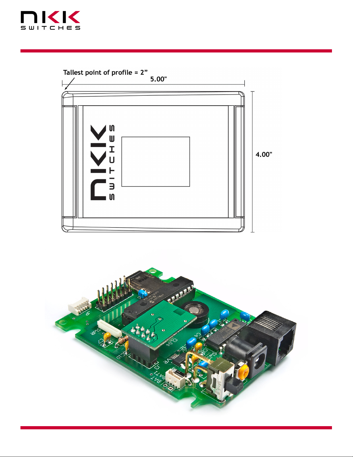
Container size
CL04 Board photo
IS-Dev Kit 8 Users Manual A.doc
Toll Free 1.877.2BUYNKK (877.228.9655) • Phone 480.991.0942 • Fax 480.998.1435
www.nkkswitches.com • Email engineering@nkkswitches.com 1209
Page 26 of 31

IS-Dev Kit-8 User Manual
7850 East Gelding Drive • Scottsdale, AZ 85260-3420
9. Key Terms & Definitions
OLED module NKK Switches’ OLED SmartSwitches and SmartDisplays.
Host Any computer, terminal, or other device that can communicate over the
RS232 line.
Controller A PCB assembly that controls one or more logic boards and the switches
associated with them. It communicates with a host over the RS232 line.
Logic Board A PCB assembly with “glue logic” for mounting switches. It is controlled by a
controller.
Byte An eight bit hex value ranging from 00H to FFH (Decimal 0 to 255). The bit
format of a byte is: (B7 B6 B5 B4 B3 B2 B1 B0) where B7 is most significant
and bit B0 is least significant bit.
Nibble/Hex digit A four bit value ranging from 0H to FH. A byte consists of two nibbles.
ASCII A byte value representing a symbol.
Communication There are two formats to transmit a byte:
Format
1. Hex format - A hex byte is transmitted without any change to it. [xxH] will
be used to denote this.
All commands and some data are sent by using this format.
2. ASCII HEX format - Each nibble of the byte is converted to ASCII code
and sent as a byte. [xxAH] will be used to denote this.
For example, the hex byte 5AH is transmitted in two bytes, 35H and 41H.
The ASCII value for 5 is 35H and the ASCII value for A is 41H.
All addresses and most data are sent using this format.
Address A two byte value ranging from 0001H to FFFFH representing the 65536
memory locations for pictures and attributes on microSD flash.
10. Firmware issues
The problems found in the most current version are listed below and get resolved in the following version.
Version V1.1 No firmware issues at this time.
IS-Dev Kit 8 Users Manual A.doc
Toll Free 1.877.2BUYNKK (877.228.9655) • Phone 480.991.0942 • Fax 480.998.1435
www.nkkswitches.com • Email engineering@nkkswitches.com 1209
Page 27 of 31
IS-Dev Kit-8 User Manual
7850 East Gelding Drive • Scottsdale, AZ 85260-3420
Appendix
Understanding Decimal, Hexadecimal and Binary Numbers
Decimal is the numbering system we use. It is called base-10. Every digit can be between 0 to 9.
The value of each digit is equal to the digit with ((Digit order) -1) zero in front.
Table 1, Base-10
Value in base-10
Digit x
Multiplication
for converting to
decimal
Digit order Nth
Example: The value of each digit of the Base-10 number 7605 is as follow:
Fourth digit: 7 with (4-1) zero = 7000
Third digit: 6 with (3-1) zero = 600
Second digit: 0 with (2-1) zero = 0
First digit: 5 with (1-1) zero = 5
Numbering system
A numbering system can be based on any number (base-N). However it has to follow the rules:
1. Each digit has to be between 0 to (Base minus one). For example:
---Each digit for Base-2 numbering system can be 0 or 1
---Each digit for Base-5 numbering system can be 0 to 4
---Each digit for base-8 numbering system can be 0 to 7
2. The value of each digit is equal to the digit with ((Digit order) -1) zeros in front.
All the operations that we use on base 10 numbering system such as addition, subtraction, multiplication,
division… works the same for all the numbering systems. The difference is the carry over will be based on the
base-number of the numbering system instead of 10.
Why do we need other base numbering systems?
Computers logic is based on two states:
Yes or No
False or True
High voltage or low voltage
10000 1000 100 10 1
(N-1)
10
digit
… … 104 103 102 101 100
…. …. Fifth
digit
Fourth
digit
Third
digit
Second
digit
First
digit
IS-Dev Kit 8 Users Manual A.doc
Toll Free 1.877.2BUYNKK (877.228.9655) • Phone 480.991.0942 • Fax 480.998.1435
www.nkkswitches.com • Email engineering@nkkswitches.com 1209
Page 28 of 31

IS-Dev Kit-8 User Manual
7850 East Gelding Drive • Scottsdale, AZ 85260-3420
Base-2 numbering system (binary)
The numbering system to accommodate the computer logic is called binary or base 2. Each digit of binary can
be 0 or 1.
Table 2, Base-2
Value in base-2
10000 1000 100 10 1
Digit x
Multiplication
(N-1)
2
… … 24 =16 23 =8 22 =4 21 =2 20 =1
for converting to
decimal
Digit order Nth
digit
…. …. Fifth
digit
Fourth
digit
Third
digit
Second
digit
First
digit
Example: The value of each digit of the Base-2 number 1010 is as follow:
Fourth digit: 1 with (4-1) zero = 1000
Third digit: 0 with (3-1) zero = 0
Second digit: 1 with (2-1) zero = 10
First digit: 0 with (1-1) zero = 0
To convert a base-2 number to decimal, multiply each digit by multiplier and add them together:
Example: converting base-2 number 1010 to decimal is as follow:
(1 x 8) + (0 x 4) + (1 x 2) + (0 x 1) = 10
To convert a decimal number to base-2 number
---divide the decimal number by 2, the remainder is the first digit of the base-2 number
--- continue dividing quotient by 2 and put the remainder as the next digit until the quotient is equal 0.
Example: Convert the decimal number 21 to base-2
21 divide by 2 = 10 with 1 remainder First digit = 1
10 divide by 2 = 5 with 0 remainder Second digit = 0
5 divide by 2 = 2 with 1 remainder Third digit = 1
2 divide by 2 = 1 with 0 remainder Fourth digit = 0
1 divide by 2 = 0 with 1 remainder Fifth digit = 1
21 decimal = 101001 base-2 or binary
The base-2 number 101001 reads as one zero one zero zero one.
IS-Dev Kit 8 Users Manual A.doc
Toll Free 1.877.2BUYNKK (877.228.9655) • Phone 480.991.0942 • Fax 480.998.1435
www.nkkswitches.com • Email engineering@nkkswitches.com 1209
Page 29 of 31
Hexadecimal
Decimal
0 0
1 1
2 10
3 11
4
5
6
7
8
9
10
11
12
13
14
15
16
17
IS-Dev Kit-8 User Manual
7850 East Gelding Drive • Scottsdale, AZ 85260-3420
Base-16 numbering system
Communicating base-2 numbers is difficult for human because of all zero’s and one’s. To make it easier to
present computer data, hexadecimal or base-16 numbering system is used. Four digit of base-2 numbering
system convert to one digit of base-16 numbering system. Since we did not have digits for 10, 11, 12, 13, 14
and 15, they were assigned letters A, B, C, D, E and F respectively.
Table 3, Number base conversion
Binary base-2
base-16
base-10
0
1
2
3
A
C
D
10
11
etc
4
5
6
7
8
9
B
E
F
etc
100
101
110
111
1000
1001
1010
1011
1100
1101
1110
1111
10000
10001
etc
Table 4, Base-16
Value in base-16
10000 1000 100 10 1
Digit x
Multiplication
for converting to
(N-1)
16
… … 164
=65536
163
=4096
162
=256
161
=16
160 =1
decimal
Digit order Nth
digit
…. …. Fifth
digit
Fourth
digit
Third
digit
Second
digit
First
digit
IS-Dev Kit 8 Users Manual A.doc
Page 30 of 31
Toll Free 1.877.2BUYNKK (877.228.9655) • Phone 480.991.0942 • Fax 480.998.1435
www.nkkswitches.com • Email engineering@nkkswitches.com 1209

IS-Dev Kit-8 User Manual
7850 East Gelding Drive • Scottsdale, AZ 85260-3420
Example: Convert 2A7 hex to decimal
Digit 3: 2 x 256 = 512
Digit 2: (10) x 16 = 160
Digit 1: 7x1 = 7
--------- 679
2A7 hex = 679 decimal
Example: Convert 925 decimal to hex
925 divide by 16 = 57 with 13 remainder First digit =D
57 divide by 16 = 3 with 9 remainder Second digit = 9
3 divide by 16 = 0 with 3 remainder Third digit = 3
925 decimal = 39D hex
Converting between hex and binary is as easy as replacing each digit of hex with equivalent 4 digit of binary.
Example: convert A5B hex to binary
A = 1010
5 = 0101
B = 1011
A5B hex = 1010 0101 1011 binary
Converting binary to hex is as easy as replacing each 4 digit of binary to equivalent digit of hex. If the binary
digits are not multiple of 4 for grouping, add enough zero to the left to make them multiple of 4.
Example: Convert 0111 1010 1111 binary to hex
1111 = F
1010= A
0111 = 7
0111 1010 1111 binary = 7AF hex
Common terms:
Bit = binary digit
Nibble = 4 binary digits
Byte = 8 binary digits = 2 nibbles = 2 HEX digits
IS-Dev Kit 8 Users Manual A.doc
Toll Free 1.877.2BUYNKK (877.228.9655) • Phone 480.991.0942 • Fax 480.998.1435
www.nkkswitches.com • Email engineering@nkkswitches.com 1209
Page 31 of 31

Mouser Electronics
Authorized Distributor
Click to View Pricing, Inventory, Delivery & Lifecycle Information:
NKK Switches:
IS-DEV KIT-8
 Loading...