

Page 1

SMARTPLUG
USER GUIDE
Page 2

SmartPlug User Guide
All Rights Reserved – nke Watteco® SmartPlug User Guide
Page 2 of 12
NOTICE
Nke Watteco reserves the right to make changes to specifications and product descriptions or to discontinue
any product or service without notice. Except as provided in Nke Watteco's Standard Terms and Conditions of
Sale for products, Nke Watteco makes no warranty, representation or guarantee regarding the suitability of its
products for any particular application nor does Nke Watteco assume any liability arising out of the application
or use of any product and specifically disclaims any and all liability, including consequential or incidental
damages.
Certain applications using semiconductor products may involve potential risks of death, personal injury or
severe property or environmental damage. Nke Watteco products are not designed, authorized or warranted
to be suitable for use in life saving or life support devices or systems. Inclusion of Nke Watteco products in such
applications is understood to be fully at the Customer's risk.
In order to minimize risks associated with the customer's application, adequate design and operating
safeguards must be provided by the customer to minimize inherent or procedural hazards.
Nke Watteco assumes no liability for applications assistance or customer product design. Nke Watteco does
not warrant or represent that any license, either express or implied, is granted un der any patent right,
copyright, mask work right, or other intellectual property right of Nke Watteco covering or relating to any
combination, machine or process in which such semiconductor products or services might be or are used. Nke
Watteco's publication of information regarding any third party's products or services does not constitute Nke
Watteco's approval, warranty and endorsement thereof.
Resale of Nke Watteco's products with statements of functionality different from or beyond the parameters
stated by Nke Watteco for that product as defined by Nke Watteco's unique part number, voids all express and
any implied warranties for that product, is considered by Nke Watteco to be an unfair and deceptive business
practice and Nke Watteco is not responsible nor liable for any such use.
Embedded software is based on Nke Watteco proprietary drivers and applicative code and operates on the
Contiki kernel from the SICS (Swedish Institute of Computer Science).
www.watteco.com
www.nke-electronics.com
© nke Watteco. All Rights Reserved
Page 3

SmartPlug User Guide
All Rights Reserved – nke Watteco® SmartPlug User Guide
Page 3 of 12
DOCUMENT HISTORY
Date
Revision
Modification Description
March 2016
1.0
First revision
Page 4

SmartPlug User Guide
All Rights Reserved – nke Watteco® SmartPlug User Guide
Page 4 of 12
CONTENTS
1 Introduction ................................................................................................................................. 5
2 Start-up ........................................................................................................................................ 5
3 Use cases ..................................................................................................................................... 7
3.1 First use: Controlling electric devices in On/Off ..............................................................................................................7
3.2 Second use: Watching the consumption of electric devices..........................................................................................7
3.3 Third use: Watching the quality of the electrical main ..................................................................................................8
4 Human Machine Interface ........................................................................................................... 9
5 Applicative Layer ....................................................................................................................... 10
5.1 Examples .......................................................................................................................................................................... 10
5.1.1 On/Off Command ....................................................................................................................................................... 10
5.1.2 Configure a standard report on the Power Quality Cluster .................................................................................... 10
5.1.3 Configure a batch report on the Simple Metering Like Cluster .............................................................................. 11
6 Appendix ................................................................................................................................... 12
6.1 SmartPlug FCC Label........................................................................................................................................................ 12
Page 5
SmartPlug User Guide
All Rights Reserved – nke Watteco® SmartPlug User Guide
Page 5 of 12
1 INTRODUCTION
This document describes the usage of the SmartPlug device. It is necessary to read the “LoRaWAN Sensors
Application Layer Description” for the applicative layer presentation and the “LoRaWAN Sensors Behavior on
Public LoRaWAN Networks” for the network layer in prerequisite for all generic information.
2 START-UP
The SmartPlug uses the main voltage as a power supply. In order to switch it on, plug it into a wall socket. The
SmartPlug will automatically start.
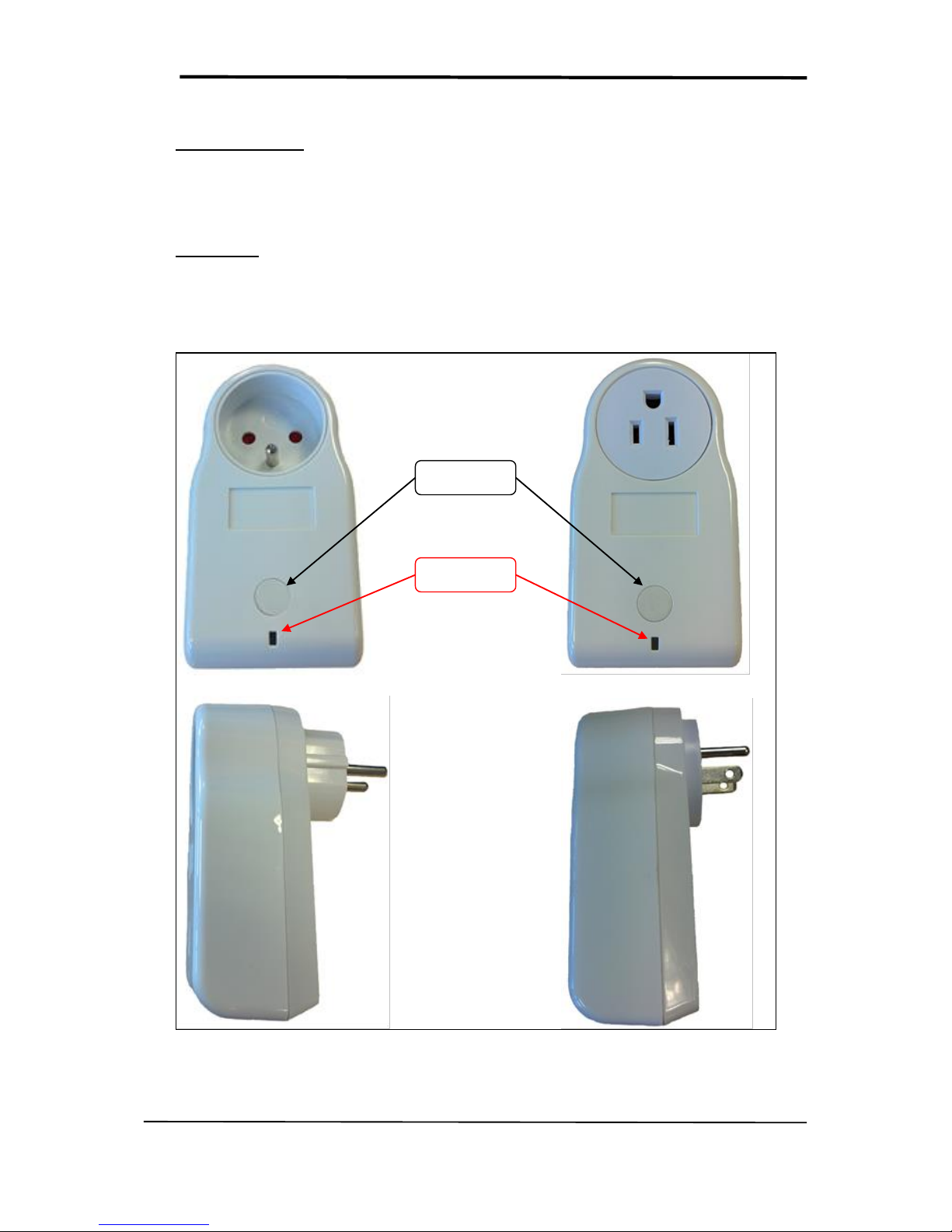
Here below can be seen illustrations of the SmartPlug in the Europe version and in the US version.
User Button
Led
FIGURE 1 - SMARTPLUG IN EU VERSION (LEFT) AND US VERSION (RIGHT)
Page 6
SmartPlug User Guide
All Rights Reserved – nke Watteco® SmartPlug User Guide
Page 6 of 12
CAUTION: This is a device connected to the mains power source, do not open the boxing while the
device is running
The SmartPlug remote is not waterproof. Thus, it has to be protected from the water splash and
cannot be used in bathrooms.
Once plugged, the SmartPlug led will flash green. As long as the SmartPlug is not paired with the LoRaWAN
network, the led will flash (cf. “LoRaWAN Sensors Behavior on Public LoRaWAN Networks” document). Once
the device is correctly paired, the led will stop flashing.
Page 7
SmartPlug User Guide
All Rights Reserved – nke Watteco® SmartPlug User Guide
Page 7 of 12
3 USE CASES
3.1 FIRST USE: CONTROLLING ELECTRIC DEVICES IN ON/OFF
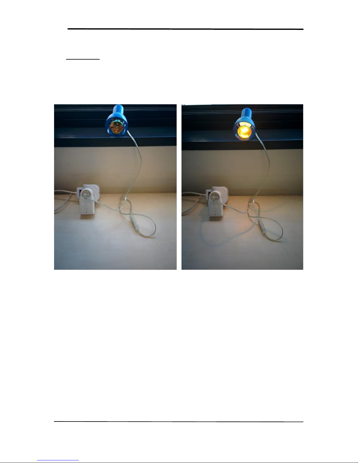
The direct application for the SmartPlug is to control electrical devices thanks to their electric supplies. Indeed
the SmartPlug is plugged inside a wall socket. Then the device to control has to be plugged on the SmartPlug’s
socket, as it can be seen on the picture here below.
Once this qu ick installation is done, the electric device can be controlled through the LoRaWAN network to be
either powered or not. This control is done thanks to the ZCL: the nke Watteco’s application layer. More
precisely, thanks to the On/Off cluster (cf. “LoRaWAN Sensors Application Layer Description” document p.22).
The exact frame to send can be found in the paragraph §5.
3.2 SECOND USE: WATCHING THE CONSUMPTION OF ELECTRIC DEVICES
Controlling an electric device in On/Off is, of course, not the only application for the SmartPlug. Indeed, this
latter integrate the necessary electronic to measure the power consumption of the electric device plugged on
it.
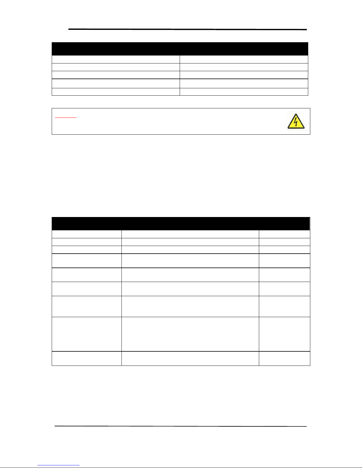
All the measured value can be found iniside the Simple-Metering Like Cluster (cf. “LoRaWAN Sensors
Application Layer Description” document p.29 and 30). Here below can be seen a table summarizing all the
value measured along with their unit.
FIGURE 2 - SMARTPLUG IN OFF AND ON STATE WITH AN ELECTRIC DEVICE
Page 8
SmartPlug User Guide
All Rights Reserved – nke Watteco® SmartPlug User Guide
Page 8 of 12
Measure
Unit
Active Energy
W.h
Reactive Energy
VAR.h
Accumulation duration
Number of sample
Active Power
W
Reactive Power
VAR
CAUTION: The maximum power that the SmartPlug can commute is 16 A for the European version
and 15 A for the US version. Please be careful to not exceed these limits.
3.3 THIRD USE: WATCHING THE QUALITY OF THE ELECTRICAL MAIN
Finally, the SmartPlug integrates as well the electronic necessary to measure and evaluate the quality of the
electrical main where it is plugged to.
In the array here below, are listed the available indicators provided by the SmartPlug to evaluate the quality of
the main. These measures are located inside the Power Quality cluster (cf. “LoRaWAN Sensors Application
Layer Description” document p.31 and 32).
Measure
Description
Unit
Frequency
Current frequency seen by the SmartPlug
(x+22232)(Hz/1000)
Frequency min.
Minimum frequency seen by the SmartPlug
(x+22232)(Hz/1000)
Frequency max.
Maximum frequency seen by the SmartPlug
(x+22232)(Hz/1000)
V
RMS
Current Root Mean Square Voltage of the main signal
seen by the SmartPlug
(V/10)
V
RMS
min.
Minimum Root Mean Square Voltage of the main signal
seen by the SmartPlug
(V/10)
V
RMS
max.
Maximum Root Mean Square Voltage of the main signal
seen by the SmartPlug
(V/10)
OverVoltageNumber
Counter incremented by the SmartPlug each time a
voltage peak exceed the value set by the “Over voltage
Threshold” in the Power Quality Cluster
Counter
SagNumber
Counter incremented by the SmartPlug each time the
main voltage is lower than the value set by the “Sag
voltage Threshold” for at least the number of half cycle
defined by the “Sag cycle Threshold” attribute in the
Power Quality Cluster
Counter
BrownoutNumber
Counter incremented by the SmartPlug each time this
latter reboot
Counter
Page 9

SmartPlug User Guide
All Rights Reserved – nke Watteco® SmartPlug User Guide
Page 9 of 12
4 HUMAN MACHINE INTERFACE
One led can be seen on the device (cf. picture in §2). This led can have 3 different colors
Green: blinking until the association to a network is don e.
Red: not used for the moment
Orange: blinking 3 time on a reset factory
A user button can be seen as well on the picture in the paragraph §2. When the utton is pressed for a long time
(7 to 8 second, until the orange led blink), the orange led will blink 3 times and a “Reset Factory” is done. To
complete the “Reset Factory” the device needs to be reboot (unplug and plug the SmartPlug will do a correct
reboot).
A “Reset Factory” allows to delete all the applicative configurations saved in the dev ice (report configuration,
batch configuration, etc.) and to delete some LoRaWAN configurations as the channel masks or the channels
added thanks to the NewChannelsReq Mac command.
Page 10
SmartPlug User Guide
All Rights Reserved – nke Watteco® SmartPlug User Guide
Page 10 of 12
5 APPLICATIVE LAYER
The SmartPlug device is an awake device. It implements the “On/Off” cluster associated with the output
controlled by relay, the “Power Quality” cluster and the “Simple-Metering-Like” cluster.
SmartPlug integrated clusters:
Cluster
Cluster name
Managed attributes
0x0000
Basic
All
0x0050
Configuration
All
0x0006
On/Off
All
0x0052
Simple Metering Like
All
0x8052
Power Quality
All
5.1 EXAMPLES
Herebelow are some examples of sending an On/Off order to the SmartPlug or configuring a report or a b atch
on either the “Simple Metering” Cluster or on the “Power Quality” cluster. If you want more informations
about the applicative layer, please refer to the “LoRaWAN Sensors Application Layer Description” document.
In the following example s, the 6lowpan header has been removed for an easier understanding. See
6LOWPAN LAYER OVER LORAWAN™ in the LoRaWAN Sensors Behavior on Public LoRaWAN Networks guide,
for more details.
5.1.1 ON/OFF COMMAND
Specification: Supply or unsupply the electric device plugged on the SmartPlug in electricity.
Solution: As there is only one On/Off output, the End Point is 0 and Cluster “On/Off” is 0x0006. The
frame to send to apply the On or the Off is a cluster command from the On/Off cluster.
Applicative payload are:
1150000600 Command OFF
1150000601 Command ON
1150000602 Command TOGGLE
5.1.2 CONFIGURE A STANDARD REPORT ON THE POWER QUALITY CLUSTER
Specification: Report all the measures allowing to evaluate the Power Quality (F, Fmin, Fmax, Vrms, Vrms
min., Vrms max., Vpeak, Vpeak min., Vpeak max., Over-Voltage Number, Sag. Number and Brownout Number).
These values has to be reported at less each 20 minutes and a minimum timing of 1 minute between 2 reports
has to be setted. Finally, an increase or a decrease of 10Vrms has to trigger a report. All other delta on the
values should not trigger a report.
Solution: As there is only one measurement input, the End Point is 0, cluster “Power Quality” is 0x8052
and attribut “Current” is 0x0000. The maximum field has to be 0x8014 to have a report all 20 minutes and the
minimum field has to be 0x8001 to have a minimal timing of 1 min between two reports. All the 0xpppp fields
have to be configured to 0x00 in order to not trigger a report except for the Vrms measure, where a delta of
10V should trigger a report, thus the value for dVrms will be 0x0064 (because the unit is V/10).
Applicative payload is:
11068052000000418001801418000000000000006400000000000000000000000000000000
Page 11

SmartPlug User Guide
All Rights Reserved – nke Watteco® SmartPlug User Guide
Page 11 of 12
5.1.3 CONFIGURE A BATCH REPORT ON THE SIMPLE METERING LIKE CLUSTER
Specification: Timestamp and record the Active Energy and the Active Power each time it decrease or
increase of respectively 10 W.h and 100 W. A batch has to be sent at least every 3h and at maximum every 10
min. The resolution needed for both of the measure is 1 W.h and 1 W.
Solution: As there is only one measurement input, the End Point is 0, cluster “Simple Metering-Like” is
0x0052 and attribut “Current Metering” is 0x0000. Here, there are two values to record in the batch, the tag
size can be 1 (label 0 and label 1 available). For the Active Energy, the delta will be 0x00000A and resolution will
be 0x000001. For the Active Power, the delta will be 0x0064 and resolution will be 0x0001.
For both of the measure, the maximum field has to be 0x80B4 to have a report at least every 3 hours and the
minimum field has to be 0x800A to have a minimal timing of 10 min between two reports.
Applicative payload is: 110600522D000000800A80B400000A0000010103800A80B40064000109
Page 12

SmartPlug User Guide
All Rights Reserved – nke Watteco® SmartPlug User Guide
Page 12 of 12
6 APPENDIX
6.1 SMARTPLUG FCC LABEL
Caution: Changes or modifications not expressly approved by the party responsible for FCC
compliance could void the user authority to operate the device. (Cf. FCC Part 15.21).
FCC ID: 2AGTV50-70-022
SmartPlug SENSOR
This device complies with Part 15 of the FCC Rules.
Operation is subject to the following two conditions: (1) this
device may not cause harmful interference and (2) this
device must accept any interference received, including
interference that may cause undesired operation.
 Loading...