

Page 1
nke
–
Marine electronics
Z.I. Kerandré – Rue Gutenberg – 56700 HENNEBONT- FRANCE
http://www.nke.fr – Customer Service tel +33 (0) 297365685
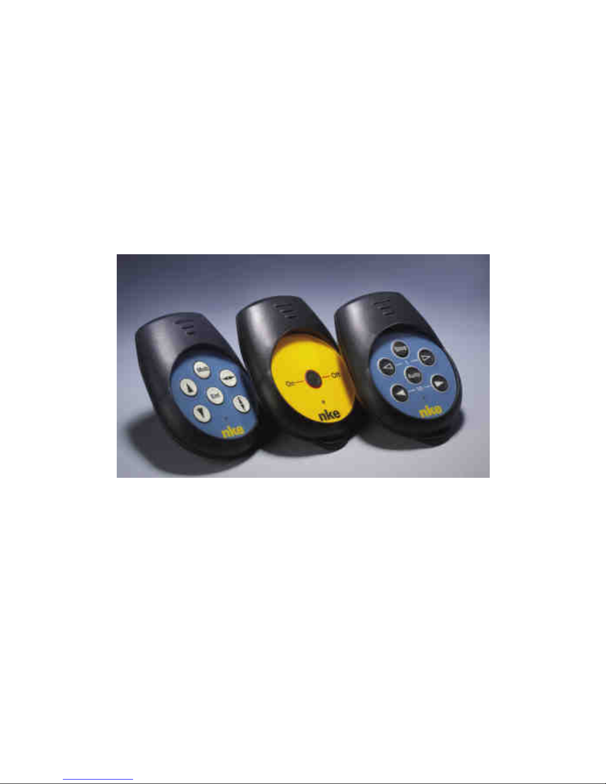
Radio Transmitter
Gyropilot transmitter 90-60-247
Multifunction display transmitter 90-60-248
Crew transmitter 90-60-251
USER GUIDE
Page 2

- 2 -
33-60-035-000-UTI_GB_Emetteurs radio
TABLE OF CONTENTS
1 PRESENTATION .................................................................................................................. 3
2 FUNCTIONS OF THE TRANSMITTERS KEYS .................................................................... 4
2.1 G
YROPILOT TRANSMITTER
..................................................................................................... 4
2.2 M
ULTIFUNCTION DISPLAY TRANSMITTER
.................................................................................. 5
2.3 C
REW TRANSMITTER
............................................................................................................. 6
3 « MAN OVER BOARD » SAFETY FUNCTION ..................................................................... 6
3.1 P
RINCIPLE OF OPERATION
...................................................................................................... 6
3.2 A
CTIVATING AND SWITCH OFF THE « MAN OVER BOARD » FUNCTION OF EACH TRANSMITTER
........ 7
3.3 A
UTOMATIC DEACTIVATION OF THE « MAN OVER BOARD » FUNCTION
.......................................... 8
3.4 A
CKNOWLEDGING AND SUSPENDING THE ALARM
...................................................................... 8
4 TECHNICAL SPECIFICATIONS ........................................................................................... 9
5 INITIALISATION AND PAIRING OF THE TRANSMITTERS ................................................ 9
Page 3
- 3 -
33-60-035-000-UTI_GB_Emetteurs radio
1 PRESENTATION
Light and ergonomic, the TOPLINE transmitters communicate with the Gyropilot and the
Multifunction displays, via the universal radio receiver which is connected to the TOPLINE
BUS. Each transmitter is paired with code, to prevent any interference with another system. It is
possible to assign 8 transmitters to the universal radio receiver of your boat. Thus, whether
you are at the helm, at the mast foot or at the bow of your boat, the transmitters allow you to
control the pilot and operate the displays. Moreover, each transmitter integrates a safety
function, which alerts the crew with an audible alarm when a man has fallen over board.
The TOPLINE range includes three types of transmitters :
- The Gyropilot transmitter allows to control the autopilot to change course, tack, change
pilot mode.
- The Multifunction display transmitter allows to control the TL25, SL50, DL18, and
Performance Multifunction displays.
- The crew transmitter integrates solely the « man over board » safety function.
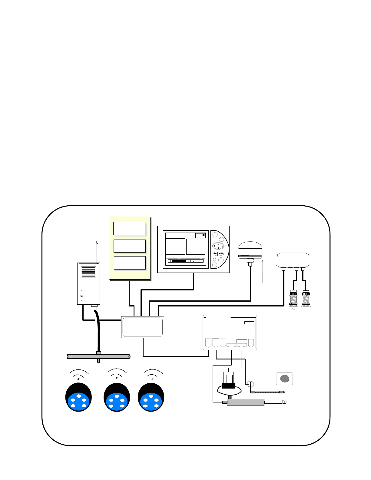
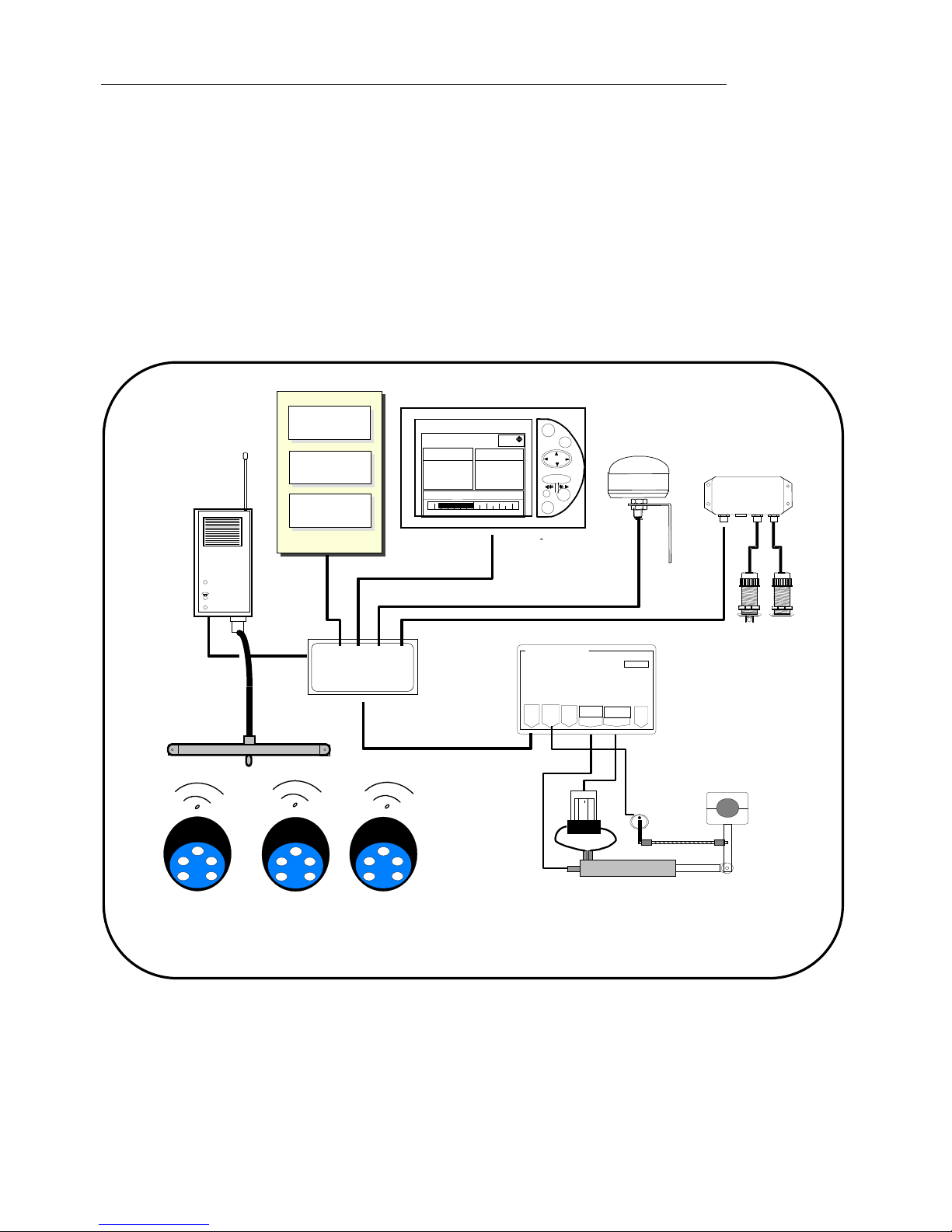
Architecture of the installation
The presence of the equipment in the following diagram is for information only, and does not
represent the equipment of your installation.
Figure 1
loch
speedo
depth
Connecting box
90-60-417
1
1
Auto
Stop
Pag
e
Ent
mode vent reel
G5
Consigne ang vent rl
Angle de
0
-10 10-20-30 30
-30°
-30°
Gyropilote Graphic
nke
M
nke Gyropilot 2
CRP
RVP
RVP
Calculateur Gyro2
Bus
Angle
Barre
Tiller
Embrayage
Alim
Pomp
réversible
nke
TL 25
16.85
VITES SURF
ANG VENT AP
105-
274°
CAP MAGNET
NOEUDS
DEGRES
DEGRES
nke
COMPAS
nke
Init
nke
Radio receiver
Outside Antenna
transmitter
Gyropilot
,
or Multifonction
Page 4
- 4 -
33-60-035-000-UTI_GB_Emetteurs radio
2 FUNCTIONS OF THE TRANSMITTERS KEYS
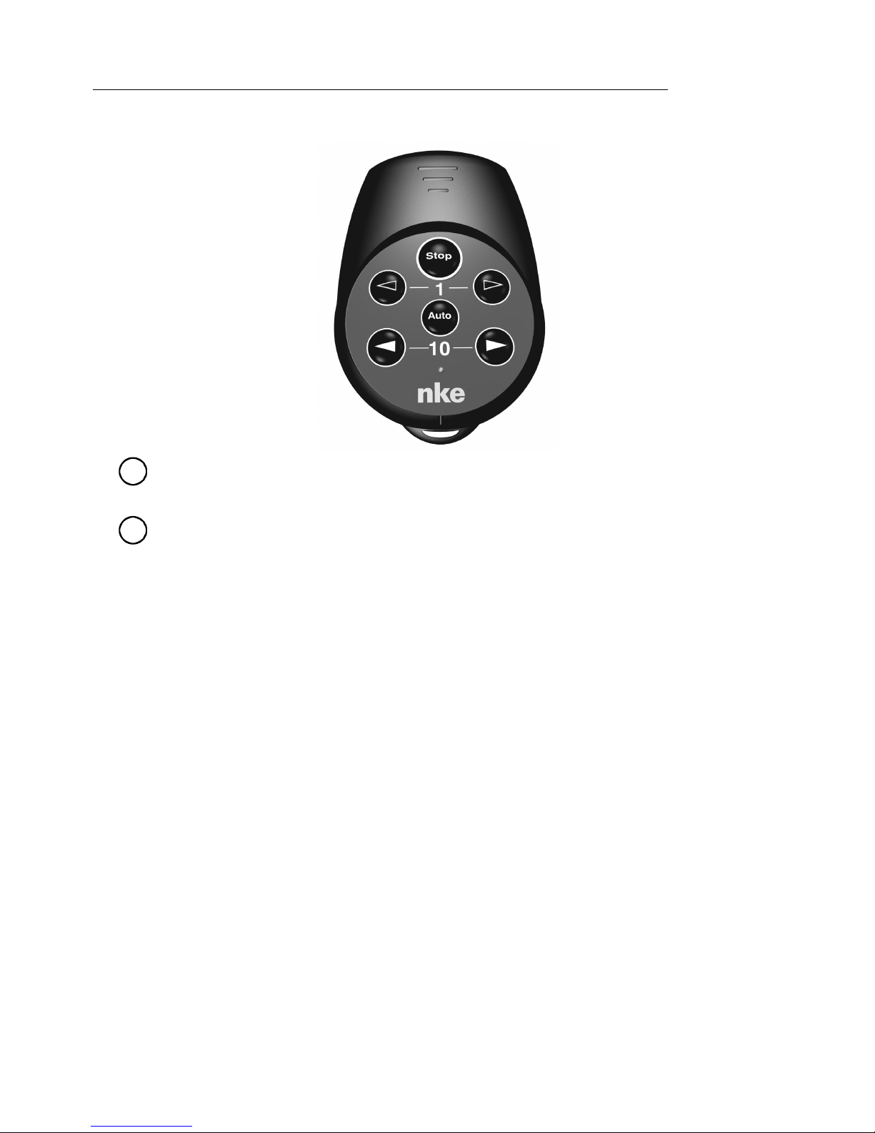
2.1 Gyropilot transmitter
-
Auto
key
Press this key to engage the Gyropilot.
-
Stop
key
Press this key to disengage the Gyropilot.
-
◄10
key
This key allows to decrease the set point by 10° on port side.
Port side tacking : press this key for 2 seconds.
-
10 ►
key
This key allows to increase the set point by 10° on starboard side.
Starboard side tacking : press this key for 2 seconds.
-
⊳
⊳ ⊳
⊳
1
key
This key allows to decrease the set point by 1° on port side.
-
1
▷▷▷▷
key
This key allows to increase the set point by 1° on starboard side.
- Activation of the « man over board » function
Press simultaneously the two keys
⊳
⊳ ⊳
⊳
and
▷▷▷▷
, for 5 seconds, and the « Man over board »
function is activated.
Page 5
- 5 -
33-60-035-000-UTI_GB_Emetteurs radio
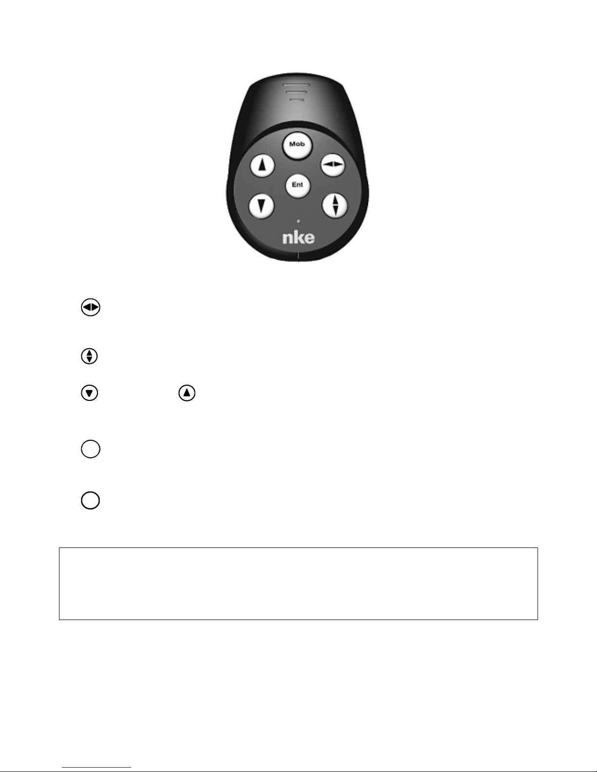
2.2 Multifunction display transmitter
- key
This key allows you to select the TOPLINE display you wish to operate.
- key
Press this key to select the display screen you wish to operate. The selected screen flickers.
- upper key and lower key
These keys allow to change the channel on display. They also allow to increment or decrement
a data which is in the process of being modified.
-
Ent
key
This key allows to access the sub-channels and to validate the settings you implement. Brief
pressure on this key also allows to set the level of lighting.
-
Mob
Man Over Board key
Press this key for 5 seconds, and the «Man Over Board» function is activated.
ATTENTION : for your multifunction display transmitter to work correctly the radio receiver must
have an address in the system that is higher than the display or displays you wish to control.
If your multifunction transmitter is not functioning this may be the problem. Please see the
installation guide for information on how to reset the radio receiver address.
Page 6
- 6 -
33-60-035-000-UTI_GB_Emetteurs radio
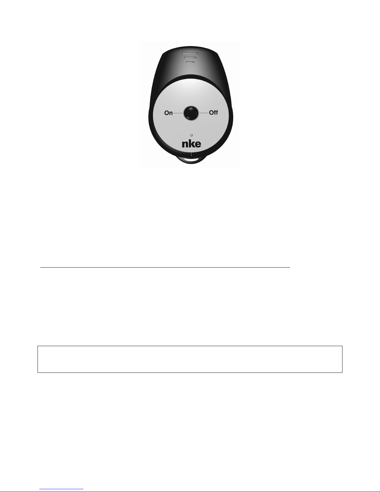
2.3 Crew transmitter
- On / Off key
Activate : press the On/Off key until the light signal stays on. When the radio receiver has
acknowledged the activation of the « man over board » function, it emits an audible beep.
When the « man over board » function is activated, the light signal flickers with a period of
approximately 2 seconds.
Deactivate : press the On/Off key until the light signal stays on. When the radio receiver has
acknowledged the deactivation of the « man over board » function, it emits 3 audible beeps.
When the « man over board » function is deactivated, the light signal is off.
3 « MAN OVER BOARD » SAFETY FUNCTION
3.1 Principle of operation
Each transmitter contains a « man over board » safety function. When a person carrying a
transmitter falls over board and the ship sails further than 50 meters away, the « man over
board » alarm will be triggered. The following five functions are activated :
− On display : the estimated heading and distance to reach the man over board are
displayed, when a speedometer and a compass are connected to the TOPLINE bus. If your
installation only contains a speedometer, then only the estimated distance will be displayed.
CAUTION : the calculation of the estimate, for the Man Over Board function, does not take into
account the drift of the boat caused by the current and the wind.
− The Gyropilot :
In crew mode : the activation of the « Man over board » function does not trigger any
action on the Gyropilot.
In alone mode :
If the boat is equipped with a masthead unit: the Gyropilot automatically switches to wind
mode, and applies a « 0°» reference in order to turn th e boat head to the wind.
If the ship is not equipped with a masthead unit : the Gyropilot automatically switches to
rudder mode, and positions the helm with a +/- 40° set point, de pending on the previous
position of the helm.
Page 7

- 7 -
33-60-035-000-UTI_GB_Emetteurs radio
− Audible alarm : the radio receiver sounds an audible alarm, until the « Man over board »
function is acknowledged.
− NMEA output
The standard 0183 NMEA frames, relative to the « Man over board » function, are transmitted
on the NMEA + output of your radio receiver :
- $ P M L R , 0 5 , 0 1 , 0 2 , 0 3 3 7 * 0 2 <cr>< lf> ; 150 ms standby
- $ T R W P L , , , , , M O B * 2 1 <cr>< lf> ; 150 ms standby
- $ P M L R , 0 5 , 0 1 , 0 2 , 0 3 3 7 * 0 2 <cr>< lf> ; 150 ms standby
- $ T R W P L , , , , , M O B * 2 1 <cr>< lf> ; 150 ms standby
- $ P M L R , 0 5 , 0 1 , 0 2 , 0 3 3 7 * 0 2 <cr>< lf>
− Connection to external relays
Two alarm outputs are available to be used by external relays :
- one of these will activate three minutes after the MOB is initiated.
- the other will activate ten minutes after the MOB is initiated.
These can be used for various alarms, e.g. to activate a loud horn, to activate a distress beacon
or to cut off the power supply to the engine.
3.2 Activating and switch off the « man over board » function of each transmitter
When powering up your installation, the « man over board » function must be activated
manually for each transmitter, since the radio receiver does not save the safety status of the
transmitters to memory.
3.2.1 Gyropilot transmitter
Activate : press the AUTO key until the light signal stays on. When the radio receiver has
acknowledged the activation of the « man over board » function, it emits an audible beep.
When the « man over board » function is activated, the light signal flickers with a period of
approximately 2 seconds.
Switch off : press the STOP key until the light signal stays on. When the radio receiver
has acknowledged the deactivation of the « man over board » function, it emits 3 audible
beeps. When the « man over board » function is deactivated, the light signal is off.
3.2.2 Multifunction display transmitter
Activate : press the
key until the light signal stays on. When the radio receiver has
acknowledged the activation of the « man over board » function, it emits an audible beep.
When the « man over board » function is activated, the light signal flickers with a period of
approximately 2 seconds.
Deactivate : press the
key until the light signal stays on. When the radio receiver has
acknowledged the deactivation of the « man over board » function, it emits 3 audible beeps.
When the « man over board » function is deactivated, the light signal is off.
Page 8
- 8 -
33-60-035-000-UTI_GB_Emetteurs radio
3.2.3 Crew transmitter
See chapter 2.3
CAUTION :
- Note that if you activate the « man over board » function of the transmitter when the radio
receiver is switched off, or out of the transmitter range, this function will not be taken into
account immediately : it will automatically be activated when the radio receiver is operating.
3.3 Automatic deactivation of the « man over board » function
In the event they are not used for a prolonged period of time, each transmitter will automatically
deactivate its own « man over board » function : one week without actuating any key. When the
transmitter deactivates its « man over board » function, the radio receiver emits a 2-beep
audible signal, to alert the user.
3.4 Acknowledging and suspending the alarm
To acknowledge the « Man over board » alarm, you must cut off the power supply of your
TOPLINE installation. This deactivation procedure is a little long, but allows to save the
information of heading and distance of the « man over board » to the memory, no matter what
actions are performed on your TOPLINE installation.
To suspend the audible alarm (during the recovery operation of the man over board, for
example), press any key on your transmitter. The estimated heading and distance to reach the
man over board remain on display.
CAUTION :
- When the « Man over Board » function is activated, the transmitter uses more battery
energy. To extend the battery life time, we recommend that you only activate this function
when you are sailing.
- If the transmitter is out of the radio receiver range, for example when you walk away from
your ship on the jetty, the « man over board » alarm will unpredictably be triggered.
Page 9

- 9 -
33-60-035-000-UTI_GB_Emetteurs radio
4 TECHNICAL SPECIFICATIONS
- Power supply : 3.6V lithium battery. Battery life time 1 to 3 years.
To replace the battery, please return the transmitter to your distributor.
- Tightness : IP68, submersible.
- Weight : 65g.
- Operating temperature : -10°C to +50°C
- Storage temperature : -20°C to +60°C
5 INITIALISATION AND PAIRING OF THE TRANSMITTERS
The initialisation of the transmitter(s) is performed at the same time as the initialisation of the
radio receiver. To do this, please refer to the installation guide of the radio receiver.
Page 10

- 10 -
33-60-035-000-UTI_GB_Emetteurs radio
NOTES
_____________________________________________________________________________________________________
_____________________________________________________________________________________________________
_____________________________________________________________________________________________________
_____________________________________________________________________________________________________
_____________________________________________________________________________________________________
_____________________________________________________________________________________________________
_____________________________________________________________________________________________________
_____________________________________________________________________________________________________
_____________________________________________________________________________________________________
_____________________________________________________________________________________________________
_____________________________________________________________________________________________________
Page 11

- 11 -
33-60-035-000-UTI_GB_Emetteurs radio
NOTES
_____________________________________________________________________________________________________
_____________________________________________________________________________________________________
_____________________________________________________________________________________________________
_____________________________________________________________________________________________________
_____________________________________________________________________________________________________
_____________________________________________________________________________________________________
_____________________________________________________________________________________________________
_____________________________________________________________________________________________________
_____________________________________________________________________________________________________
_____________________________________________________________________________________________________
_____________________________________________________________________________________________________
Page 12

- 12 -
33-60-035-000-UTI_GB_Emetteurs radio
NOTES
_____________________________________________________________________________________________________
_____________________________________________________________________________________________________
_____________________________________________________________________________________________________
_____________________________________________________________________________________________________
_____________________________________________________________________________________________________
_____________________________________________________________________________________________________
_____________________________________________________________________________________________________
_____________________________________________________________________________________________________
_____________________________________________________________________________________________________
_____________________________________________________________________________________________________
_____________________________________________________________________________________________________
Page 13
nke
–
Sailing competition
Z.I. Kerandré – Rue Gutenberg – 56700 HENNEBONT- FRANCE
http://www.nke.fr – After sale service n° 33 297 365 685
Universal radio receiver
Product reference : 90-60-250
INSTALLATION GUIDE
Page 14

- 2 - 33-60-034-001_INST_GB_ radio receiver
TABLE OF CONTENTS
1 PRESENTATION .................................................................................................................. 3
2 “MAN OVER BOARD” SAFETY FUNCTION ....................................................................... 4
2.1 G
YROPILOT BEHAVIOUR
......................................................................................................... 4
2.2 S
USPENDING AND DISABLING THE “MAN OVER BOARD” ALARM
, .................................................. 5
3 RECEIVER AND OFFSET ANTENNA INSTALLATION ....................................................... 5
3.1 P
ACKING LIST FOR THE RECEIVER
90-60-250.......................................................................... 5
3.2 L
IST OF ACCESSORIES
........................................................................................................... 5
3.3 S
PECIFIC PRECAUTIONS FOR THE INSTALLATION OF THE RADIO SYSTEM
..................................... 5
3.4 S
PECIFIC PRECAUTIONS FOR SHIPS MADE WITH METAL AND CARBON
......................................... 7
3.5 P
OSITION AND INSTALLATION OF THE RADIO RECEIVER HOUSING
............................................... 8
3.6 C
HECKING THE RADIO TRANSMISSION FROM THE TRANSMITTERS TO THE RADIO RECEIVER
........... 8
4 CONNECTION TO THE TOPLINE BUS AND TO THE NMEA BUS..................................... 9
4.1 C
ONNECTION OF EXTERNAL RELAYS
..................................................................................... 10
5 RECEIVER INITIALIZATION AND PAIRING OF THE TRANSMITTERS ........................... 11
5.1 D
ESCRIPTION OF THE RADIO RECEIVER
................................................................................ 11
5.2 A
BOUT THE PAIRING
………………………………………………………………………………. 12
5.3 I
NITIALIZATION OF THE RADIO RECEIVER
…………………………………………………………..12
5.4 P
AIRING THE GYROPILOT TRANSMITTER WITH THE RADIO RECEIVER
........................................ 12
5.5 P
AIRING THE MULTIFUNCTION TRANSMITTER WITH THE RADIO RECEIVER
.................................. 13
5.6 P
AIRING THE CREW TRANSMITTER WITH THE RADIO RECEIVER
................................................ 13
5.7 S
ET ANADDRESS TO THE RADIO RECEIVER
…………………………….................................. 13
6 DIAGNOSTIC FOR 1ST LEVEL TROUBLESHOOTING. ..................................................... 14
7 TECHNICAL SPECIFICATIONS ....................................................................................... 155
Page 15
- 3 - 33-60-034-001_INST_GB_ radio receiver
1
PRESENTATION
The universal radio receiver is an interface allowing the communication between TOPLINE
transmitters and the Gyropilot or the Multifunction displays.
Three types of TOPLINE transmitters communicate with the universal radio receiver :
- The Gyropilot transmitter.
- The Multifunction display transmitter.
- The crew transmitter.
The radio receiver is connected to the TOPLINE bus of your installation. It is designed to
communicate with 8 transmitters.
Figure 1
Interface loch sondeur
90-60-450
loch
speedo
depth
Connecting box
1
1
Auto
Stop
Pag
e
Ent
mode vent reel
G5
Consigne ang vent rl
Angle de
barre
0
-10 10
-20 -30
30
-30°
-30°
M
nke Gyrop
i
lot 2
CRP
RVP
RVP
Calculateur
Bus
Angle
Barre
Tiller
Embrayage
Alim
.
Pomp
e
réversible
nke
TL 25
16.85
VITES SURF
ANG VENT AP
105-
274°
CAP MAGNET
NOEUDS
DEGRES
DEGRES
nke
Fluxgate Compass
nke
Init
nke
Radio receiver
Gyropilot
Multifonction
Transmitter
Crew
External
Antenna
Page 16

- 4 - 33-60-034-001_INST_GB_ radio receiver
2 “MAN OVER BOARD” SAFETY FUNCTION
Each transmitter integrates a “man over board” safety function. When a person carrying a
transmitter falls over board and the ship sails further than 50 metres away, the “man over
board” alarm is triggered. The following functions are activated:
−
On display: the estimated heading and distance to reach the man over board are displayed
when a speedometer and a compass are connected to the TOPLINE bus. If your installation
only comprises a speedometer, then only the estimated distance will be displayed.
− The audible alarm: the radio receiver sounds an audible alarm, until the “man over board”
function is acknowledged (see chapter 2.1).
− The NMEA output
Two standard 0183 NMEA frames, relative to the “Man over board” function, are transmitted on the
NMEA + output 3 times per second (see chapter 4):
MLR frame
$ P M L R , 0 5 , 0 1 , 0 2 , 0 3 3 7 * 0 2 <cr>< lf>
| | | Checksum
| | Data bytes (here 02 = MOB key on the GPS)
| Number of data bytes (01 = only 1 data byte)
Type of phrase (05 = simulating key pressing on the keyboard)
This frame launches an “MOB” procedure on compatible MLR GPS.
WayPoint Location
$ T R W P L , , , , , M O B * 2 1 <cr>< lf>
I
WayPoint Name
Note that the parameters of these frames are constant. The radio receiver does not calculate
any parameter in these phrases.
2.1 Gyropilot behaviour
In alone mode:
the ship is equipped with a masthead unit and the gyropilot is set on “auto”: The
Gyropilot automatically switches to wind mode and applies a “0°” set point, in order to position
the ship into the wind.
The Gyropilot is set on “stop”: The Gyropilot automatically switches to “auto” and “rudder
mode”, and positions the helm with a +/- 40° set point in relation to the previous position of the
helm.
If the ship is not equipped with a masthead unit : the Gyropilot automatically switches to
“rudder mode”, and positions the helm with a +/- 40° set point in relation to the previous
position of the helm.
Page 17

- 5 - 33-60-034-001_INST_GB_ radio receiver
In crew mode: the activation of the “man over board” function does not trigger any
action on the Gyropilot.
(Reminder: The crew / alone mode selection can only be carried out with GPG V1.42 or above
and calculator V2.30 from 21/07/03 or a later version.)
2.2 Suspending and disabling the “Man over board” alarm,
To suspend the audible alarm (during the recovery operation of the man over board, for
example), press any key on your transmitter. The estimated heading and distance to reach the
man over board remain on display.
To disable the “Man over board” alarm, you must cut off the power supply of your TOPLINE
installation.
Note that if you do not cut off the power supply, the information on heading and distance to the
“man over board” are saved to the memory, no matter what commands are performed on your
TOPLINE installation.
3
RECEIVER AND OFFSET ANTENNA INSTALLATION
3.1 Packing list for the receiver 90-60-250
− One radio receiver equipped with 3 metres of cable.
− One mounting bracket.
− One outside receiving antenna equipped with 5 metres of cable.
− One guide.
3.2 List of accessories
− Outside antenna : 90-60-277
− Gyropilot transmitter : 90-60-247
− Multifunction transmitter : 90-60-248
− Crew transmitter : 90-60-251
− TOPLINE terminal box : 90-60-121 or 90-60-417 (with NMEA input).
− TOPLINE bus cable 20-61-001.
3.3 Specific precautions for the installation of the radio system
On the ship, the nke radio system comprises :
− One receiver equipped with a small antenna.
− One outside antenna.
− One or more TOPLINE radio transmitters.
The propagation of radio waves, emitted by the transmitters to the receiver antennas, can be
more or less disrupted by the boat and its equipment. In order to achieve good radio
transmission, it is thus important to position the offset antenna and that of the radio receiver
Page 18
- 6 - 33-60-034-001_INST_GB_ radio receiver
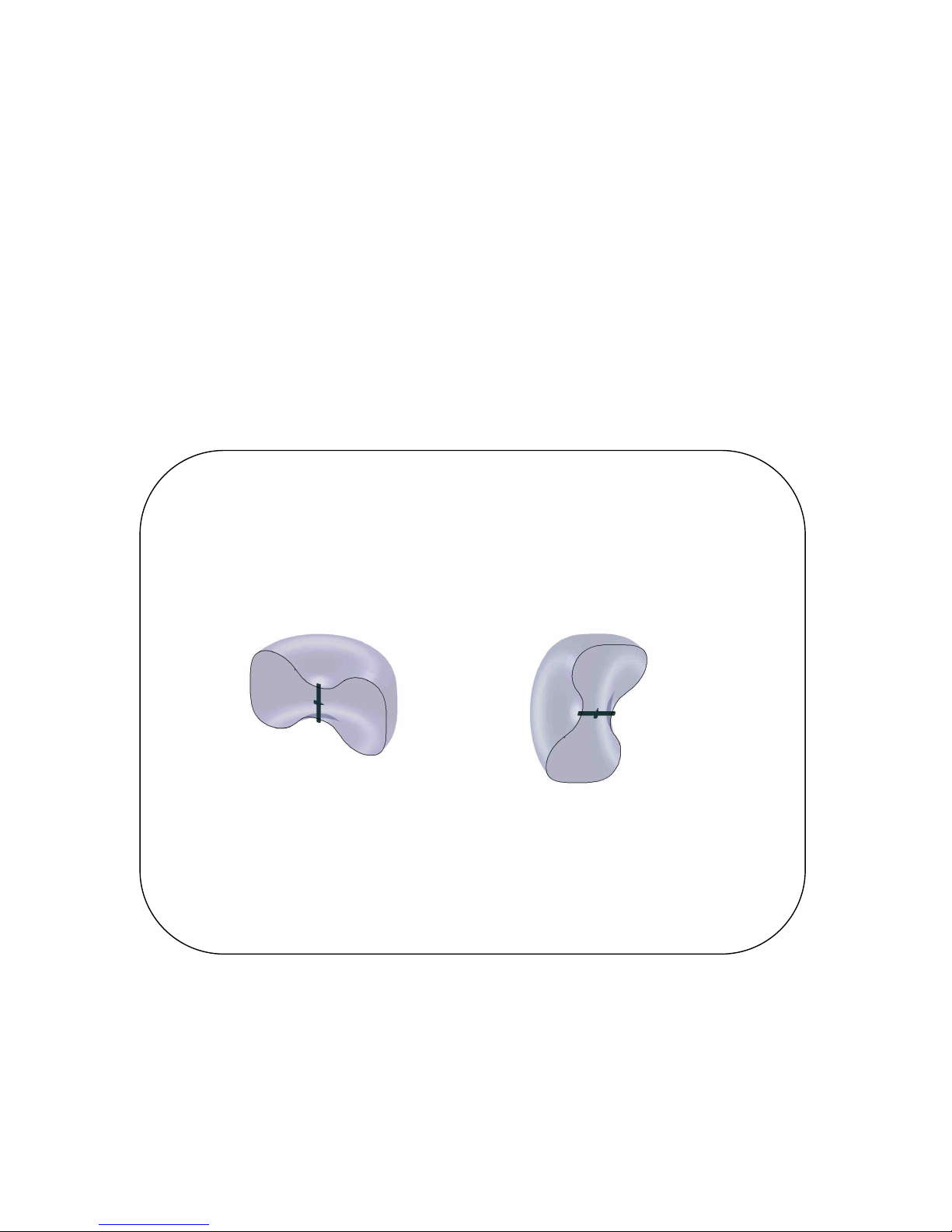
judiciously. Figure 2 below describes the radio spectrum of the offset antenna. We observe that
wave reception is at its maximum perpendicular to the antenna, and lower towards the
extremities. Position the outside antenna so that the spectrum covers the deck of your ship as
much as possible.
We recommend the optimum configuration of installation below :
− The offset antenna is positioned horizontally and perpendicular to the axis of the boat.
− The offset antenna is placed at the centre of the area where the transmitters are used.
− The cable outlet of the offset antenna must run perpendicular to the antenna, over a length
of at least 30cm.
− The receiver housing and its antenna are positioned vertically.
Reception of the
antenna in vertical
position
Reception of the
antenna in horizontal
position
Figure 2
Note that scale of the radiation diagram is not representative ; it
only provides the shape of the spectrum.
866MHz radio spectrum of the offset antenna
Page 19
- 7 - 33-60-034-001_INST_GB_ radio receiver
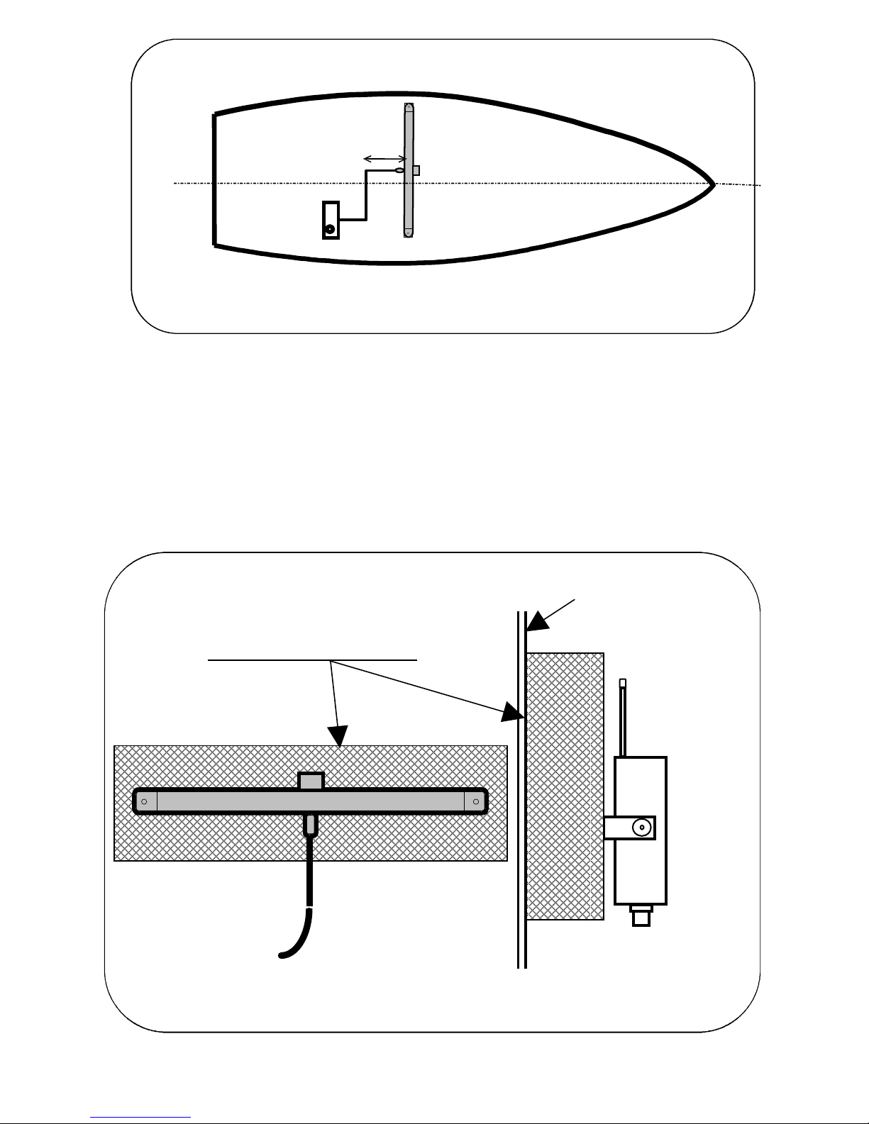
3.4 Specific precautions for boats made with metal and carbon
Boats made with metal (steel, aluminium, etc.) and carbon, are sometimes impervious to radio
waves. Thus we recommend that you install the offset antenna outside the hull of the boat. The
radio receiver must be installed inside.
Moreover, when the mounting wall is made out of metal or carbon, it is necessary to fit an
insulant (wood or plastic), at least five centimetre thick, between the antennas, and the
mounting wall (see figure 4).
nke
Metal wall or
Made of carbon
Figure 4 :move away antenna from en metal or carbon wall
Isolating material thickness 5cm
antenn
Receiver antenna
nk
e
Figure 3
Receiver radio
Antenna
30cm
Page 20

- 8 - 33-60-034-001_INST_GB_ radio receiver
3.5 Position and installation of the radio receiver housing
The receiver housing is non waterproof, and must therefore be placed inside the boat, in a dry
and protected place. The receiver is delivered with a mounting bracket. Attach the bracket on
the bulkhead with 2 screws of 5 mm diameter (screws not included).
The radio receiver, equipped with a small antenna, must be mounted vertically.
3.6 Checking the radio transmission from the transmitters to the radio receiver
You have determined the locations of the radio receiver and offset antenna. Before fitting them
definitively, check the quality of radio reception of your installation. In order to do that, use a
TOPLINE radio transmitter and check that it controls your instruments, everywhere on the deck
of the boat.
Page 21
- 9 - 33-60-034-001_INST_GB_ radio receiver
4
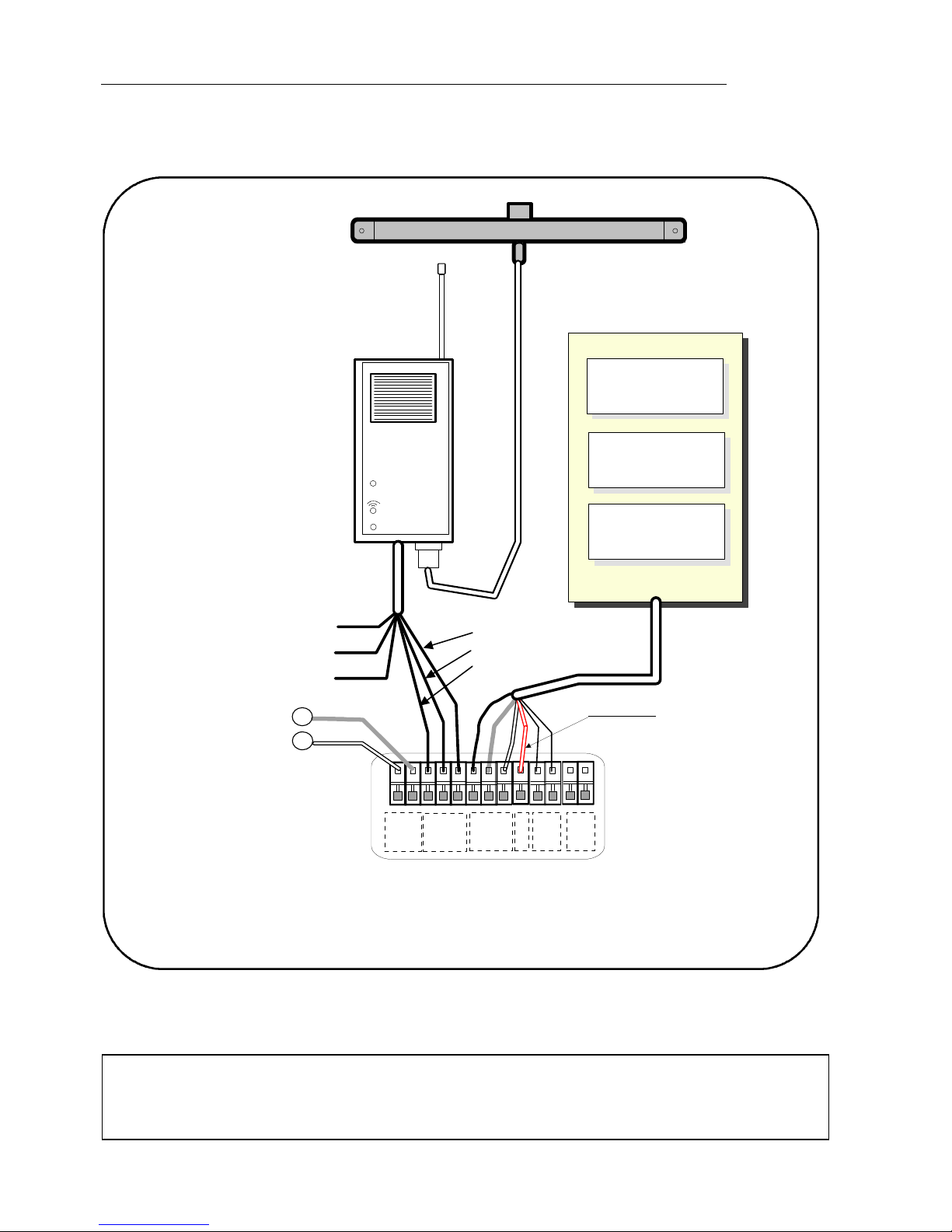
CONNECTION TO THE TOPLINE BUS AND TO THE NMEA BUS
1.
Make the receiver bus cable run to the TOPLINE terminal box of your installation.
2. Connect the bus cable inside the terminal box.
If you reduce the length of the bus cable, strip and galvanise the wires before connecting them
inside the terminal box.
CAUTION :
-
The connection of the radio receiver must be carried out with the installation power
switched off.
BLANC
GND
NOIR
BLANC
GND
NOIR
1
2
V
G
N
D
NMEA-
NMEA+
NMEA-
NMEA+
init
12Vdc supply
connecting box
90-60-417
-
GND shield
DATA black
12VDC white
Figure 5 : connecting to Topline bus
+
init wire TL25
nke
TL 25
16.85
VITES SURF
ANG VENT AP
105-
274°
CAP MAGNET
NOEUDS
DEGRES
DEGRES
nke
Init
nke
Yellow: output NMEA +
Red: MOB relay
Green: relay
Black: data
Braid+blue: GND
White: 12V
Radio receiver
Outside Antenna
Page 22
- 10 - 33-60-034-001_INST_GB_ radio receiver
Identification of the cable wires
Identification of the receiver cable wires Topline bus
Coupled braid
and blue
Earth common to the Topline bus, the
NMEA bus and relay contacts.
Braid
White wire +12V White
Black wire
Topline data
Black
Yellow wire NMEA + output
Red wire relay contact man over board alarm
Green wire relay contact beacon activation
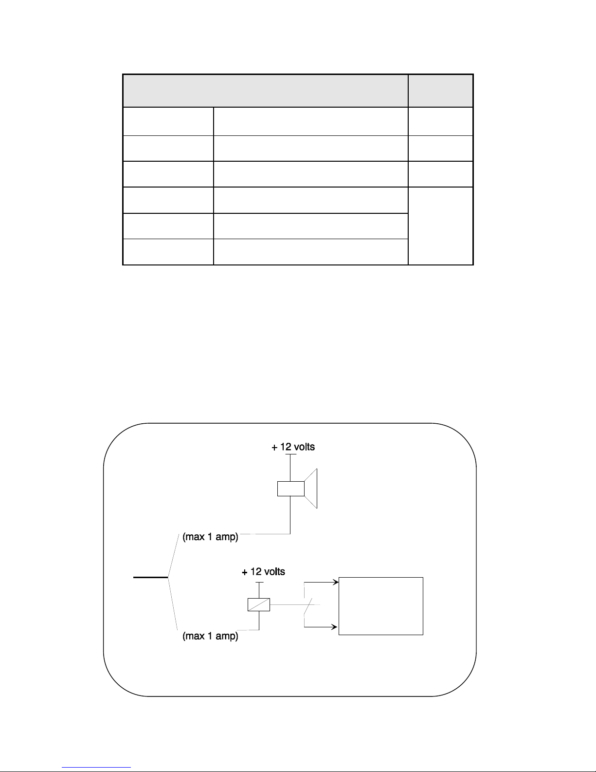
4.1 Connection of external relays
Two alarm outputs are available to be used by external relays:
- one of these will activate three minutes after the MOB is initiated
- the other will activate ten minutes after the MOB is initiated
These can be used for various alarms, e.g. to activate a loud horn, to activate a distress beacon
or to cut off the power supple to the engine.
The maximum current carrying capacity of the relay is 1A.
Red
Beacon or
other
equipment
Page 23
- 11 - 33-60-034-001_INST_GB_ radio receiver
5
RECEIVER INITIALIZATION AND PAIRING OF THE TRANSMITTERS
For the initialization of the radio receiver and transmitter(s) (Gyropilot, Multifunction and
crew) at first power-up, you must pair up the transmitter(s) with the radio receiver. It will take
an address on the bus at this time.
The radio receiver is delivered with the address set as 0. During the initialization, it will
automatically insert itself in the list of instruments of the TOPLINE bus of your installation, at
first free address comprised between 2 and 20.
5.1 Description of the radio receiver
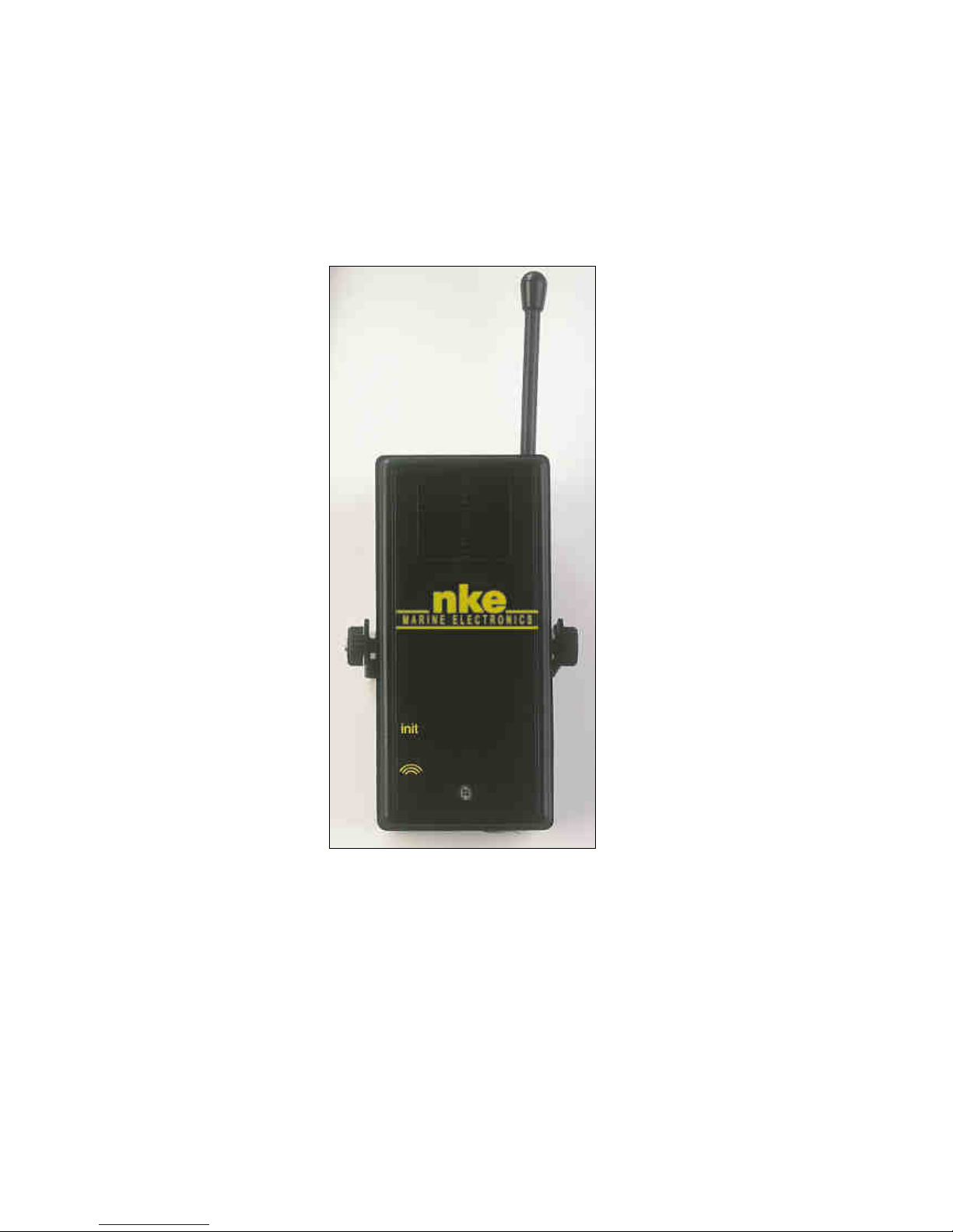
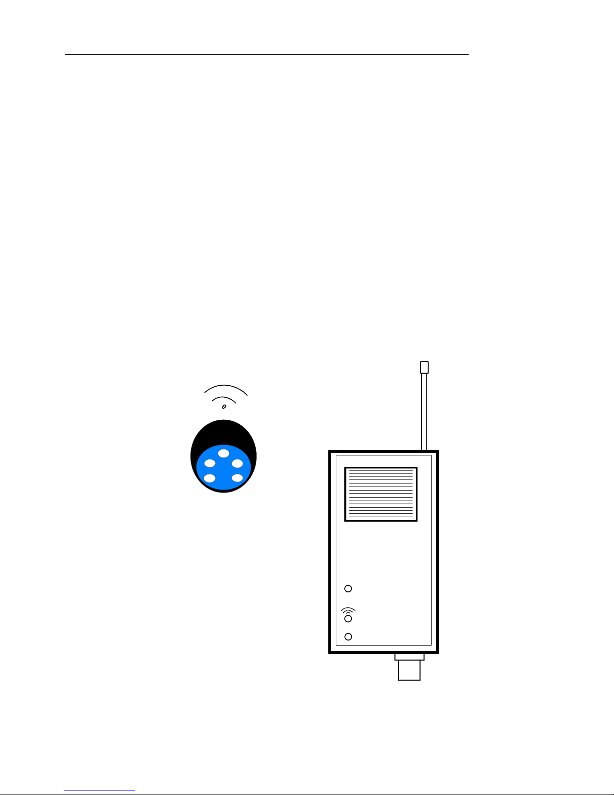
On the front panel of the radio receiver, you will find the « Init » push-button. Use a small
diameter screwdriver to actuate this push-button.
Underneath, two signal lights indicate the radio receiver status :
− The upper red signal light flickers when the transmitters communicate with the antenna
integrated with the receiver. This signal light is permanently on, during the transmitter pairing
procedure.
− The bottom red signal light flickers when the transmitters communicate with the outside
antenna.
nke
Init
Initialisation switch
Led of receiving of the integrated antenna
Led of outside antenna
Figure 7 :Radio receiver
Transmitter
Page 24

- 12 - 33-60-034-001_INST_GB_ radio receiver
5.2 About the pairing
Caution before you continue !
You must disable the MOB function on the remote radio devices before entering the pairing
procedure because the transmission of MOB messages to the receiver can disrupt the pairings.
For the Gyropilot Remote you must press on the STOP key of the transmitter until the signal
light stays on. When you release the STOP key the light will go out and the MOB is disabled.
For the Multifunction Remote you must press on the ◄► key until the signal light stays on.
When you release the ◄► key the light will go out and the MOB is disabled.
With the Crew MOB Transmitter, if the light is blinking you must press the ON button until the
signal light stays on. When you release the ON button the light will go out and the MOB is
disabled. If the light is blinking the unit is activated.
5.3 Initialization of the radio receiver
Press the init button until the red light signal stays on, release the button and the receiver will
start to beep at 1 second intervals.
You now have one minute to start the pairing procedure, at completion of each pairing cycle the
receiver will continue to beep for one minute to allow you to pair the next unit.
5.4 Pairing the Gyropilot transmitter with the receiver
1- Hold down the STOP key for three beeps, release the STOP key
2- Press and release the STOP key once
3- Hold down the STOP key for approximately three beeps, you will hear a long beep if the
pairing is successful. You will hear three short beeps if there is a problem with the pairing
and you must attempt the pairing again.
To exit the pairing procedure
The pairing procedure will automatically end one minute after the last device is paired or you
may press the init button to end the procedure at any time.
Important :
− All Gyropilot, Multifunction and Crew MOB devices used with an individual radio Receiver
must be paired at the same time. The pairing of any single device subsequent to the
initial pairings will delete older pairings and they must all be redone.
−
The maximum number of devices for a radio receiver to be paired is 8.
−
Once you enter the initialization procedure you will need to have all your devices at hand
to complete the process.
−
Below the procedures for pairing the Gyropilot, Multifunction and Crew MOB devices are
detailed.
Page 25

- 13 - 33-60-034-001_INST_GB_ radio receiver
5.5 Pairing of a Multifunction transmitter with the receiver
1- Hold down the ENT key for three beeps, release the ENTER key
2- Press and release the ENT key once
3- Hold down the ENT key for approximately three beeps, you will hear a long beep if the
pairing is successful. You will hear three short beeps if there is a problem with the pairing
and you must attempt the pairing again.
To exit the pairing procedure
The pairing procedure will automatically end one minute after the last device is paired or you
may press the init button to end the procedure at any time.
5.6 Pairing of a Crew transmitter with the receiver
1- Hold down the ON/OFF key for three beeps, release the ON/OFF key
2- Press and release the ON/OFF key once
3- Hold down the ON/OFF key for approximately three beeps, you will hear a long beep if
the pairing is successful. You will hear three short beeps if there is a problem with the
pairing and you must attempt the pairing again
To exit the pairing procedure
The pairing procedure will automatically end one minute after the last device is paired or you
may press the init button to end the procedure at any time.
5.7 Set an address to the radio receiver
This operation allows the radio receiver to take an address on the TOPLINE bus :
− After pairing up the transmitter(s), press one of the keys of a transmitter,
− The master display then indicates « Creating list » (the other multifunction displays indicate
«List»).
−
an address is assigned to the radio receiver, and this address is saved to the memory.
Page 26

- 14 - 33-60-034-001_INST_GB_ radio receiver
6
DIAGNOSTIC FOR 1ST LEVEL TROUBLESHOOTING.
This chapter can help you rapidly resolve minor problems which do not require the intervention
of a specialist. Before contacting technical support, please check the troubleshooting table
below.
Problem Possible causes and solutions
The Topline bus does not detect the radio receiver.
The bus cable is not or is badly connected to the terminal box : check the
plugging and the connection inside the terminal box. Check the state of
the cables : they must not show any sign of wear or cut.
The radio receiver emits an intermittent audible signal every 5
seconds.
The radio receiver stopped receiving the Topline Bus signal for more
than 10 seconds : the bus cable is not or is badly connected to the
terminal box : check the plugging and the connection inside the terminal
box.
The Multifonction transmitter no longer acts on your displays.
The Gyropilot transmitter no longer controls the pilot. The radio
system is no longer operating.
The crew transmitter does not trigger the « man over board »
alarm.
- The radio transmitter is powered by a battery. The life time of the battery
is 1 to 3 years. It may need to be replaced.
- The transmitter is not paired with the radio receiver : perform the
pairing of the transmitter ( see chapter on initialisation).
- The radio receiver and its antenna do not receive the messages from
the transmitter. Check that the offset antenna is properly connected to
the receiver. Check that the antenna is not located near an object made
with metal or carbon.
Page 27
- 15 - 33-60-034-001_INST_GB_ radio receiver
7
TECHNICAL SPECIFICATIONS
Radio receiver
- Range of the radio system : 25 metre radius.
- Frequency: 868,300 MHz
- Sensibility: -100dBm
- Tightness of the housing : IP20. Non waterproof housing.
- 3 metre cable.
- Weight : 260 g
- Operating temperature : -10°C to +50°C
- Storage temperature : -20°C to +60°C
Offset antenna
- Tightness : IP68
- 6 metre cable fitted with a BNC connector.
- Weight : 270 g
-
Operating temperature : -10°C to +50°C
-
Storage temperature : -20°C to +60°C
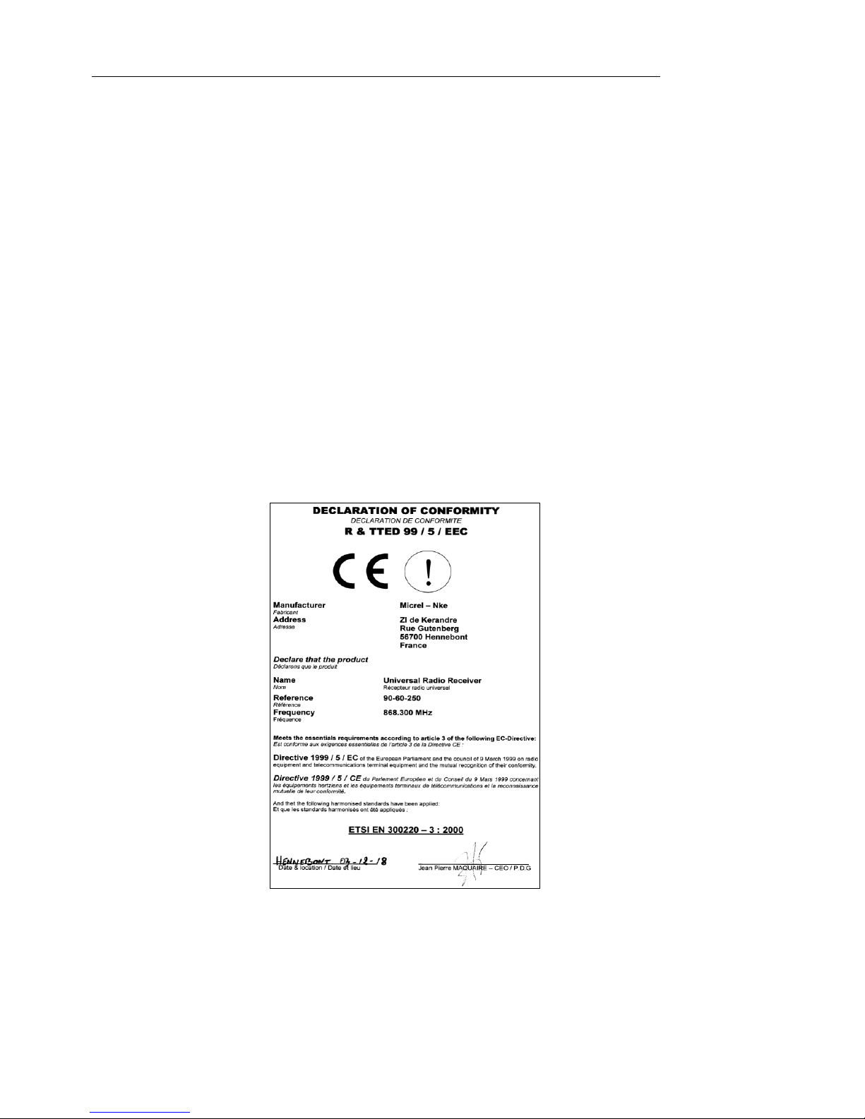
The radio receiver is in compliance with the EMC standards.
Page 28

- 16 - 33-60-034-001_INST_GB_ radio receiver
NOTES
_________________________________________________________________
_________________________________________________________________
_________________________________________________________________
_________________________________________________________________
_________________________________________________________________
_________________________________________________________________
_________________________________________________________________
_________________________________________________________________
_________________________________________________________________
_________________________________________________________________
_________________________________________________________________
_________________________________________________________________
_________________________________________________________________
_________________________________________________________________
_________________________________________________________________
_________________________________________________________________
_________________________________________________________________
_____________________________________________________
 Loading...