

Page 1

NJS052
DJX1800U
2U MIXER with USB
Page 2

SRS Audio effect
Professional 2-channel DJ mixer
Super-smooth ULTRAGLIDE fades with up to 3500,000 life cycles
Gain and 2-band kill EQ (-32dB) per channel
Extremely precise assignable level meter with peak hold function
Extremely low-noise ULN (Ultra Low-Noise) design, like those on
professional studio consoles
Gold plated cinch phono sockets for excellent audio qualities
Super-rugged construction ensures long life, even under the most
demanding condition
Page 3

1. INTRODUCTION
With the PRO MIXER, you have purchased an absolutely state-of-the-art DJ
mixer. Its extensive features open the door to new and creative ways of working,
while making it suitable for a variety of professional applications. At the same
time, the unit is extremely easy to operate, allowing you to completely unfold
creativity.
Time waits for no one, and neither you nor we want to be left behind. That’s why
we invested months of research and development in creating a DJ mixer that
offers up-to date features and technology to give you a true cutting edge for your
performances. Fully optimized for dance club applications and DJ systems, the
UNIT promises full-blown DJ’ing fun-and success.
Let’s be honest: nobody likes reading users’ manuals. We know you want to plug
in and get jammin, but please take the time to read the following instructions.
We’ve kept them as short as possible, and it will be well worth the few minutes it
takes you. Armed with a thorough understanding of the UNIT’s features and
functions, you’ll be able to get the most out of this exciting product.
The following instructions will give you a brief run-down on the
terminology and functions of the unit. After reading, please store this
manual in a safe place for future reference.
Your PRO MIXER was carefully packed in the factory and the packaging is
designed to protect the unit against rough handing. Nevertheless, we recommend
that you carefully examine packaging and contents for any signs of physical
damage which may have occurred during transit.
Never let unsupervised children play with the unit or with its packaging.
Please dispose of all packaging materials in an environmentally
friendly fashion
Page 4
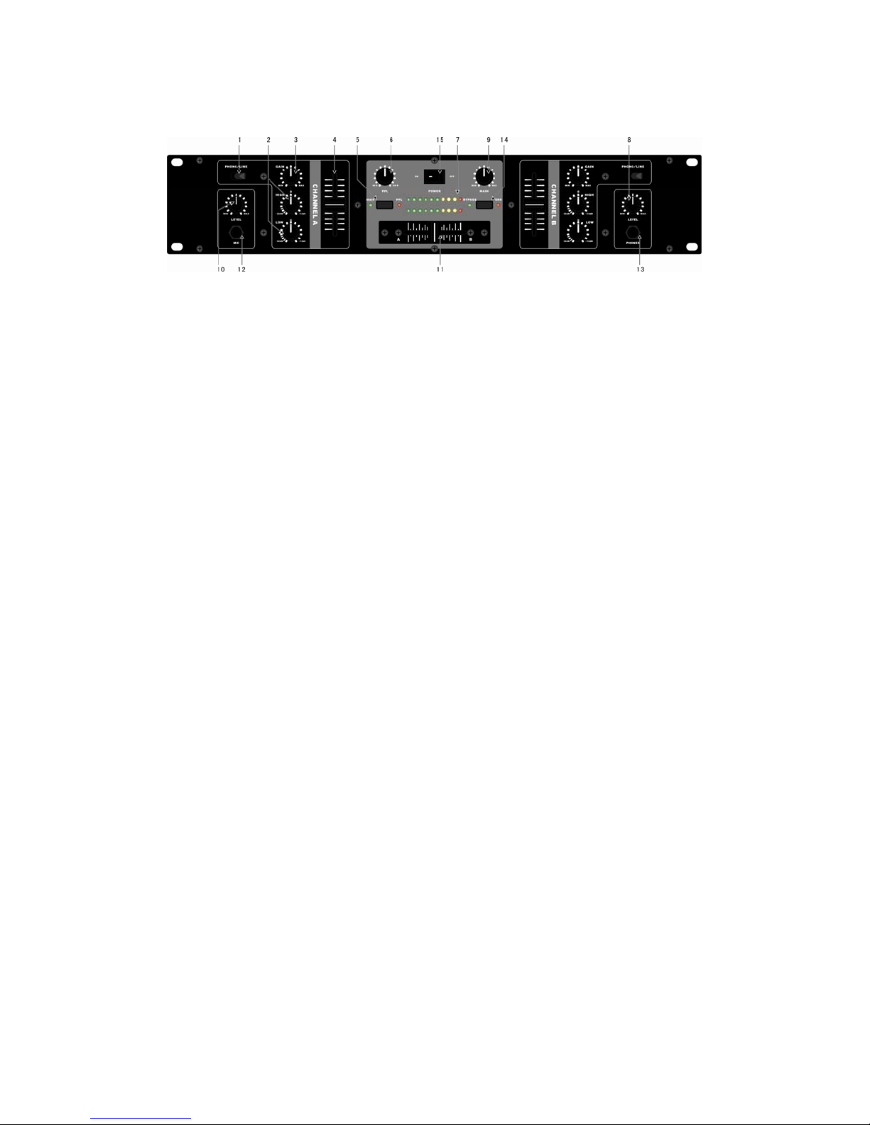
2. FRONT PANEL
The PHONO/LINE switch selects one of the input pairs on the respective channel.
1.
The “PHONO” setting (and inputs) is intended for turntables; for all other signal
sources, i.e. a CD or MD player, use the “LINE” setting and inputs.
Never connect line-level equipment to the highly sensitive PHONO
inputs! The output levels of PHONO cartridge systems are in the
millivolt range, whereas CD and MD players, as well as tape decks,
provide outputs levels in the volt range. In other words, the level of line
signals is up to 100 times higher than PHONO output levels.
Do not turn up the volume when there is no turntable connected to the
PHONO input terminals. Doing so will cause humming or noise. When
not connecting a turntable, keeps the “LINE” setting.
2. Each of the two input channels is equipped with a 2-BAND EQUALIZER with kill
characteristic. The maximum amount of attenuation (-32dB) is much higher than
the maximum boost (+12dB), allowing entire frequency spectrums to be “removed”
from a track.
3. The GAIN control is used to adjust the input signal level.
The overall level of your signal is also affected by the EQ settings. It’s a
good idea to adjust the equalizer before you set the level with the GAIN
control.
4. The CHANNEL fader adjusts the final channel volume.
The PFL signal is a pre-fader headphones signal, enabling you to
pre-listen to a signal source without affecting the main signal.
Page 5

5. The MAIN/PFL button allows you to route either the MAIN or PFL signal to the
display Remember. “PFL” is your pre-listening or headphone signal and “MAIN” is
the signal assigned to the outputs of the unit.
6. The PFL control lets you fade between channels A and B.
7. The displays the level of the signal selected via the MAIN/PFL button.
8. The LEVEL control determines the volume of the headphones signal.
In PFL mode, the channel A signal is displayed on the TOP side of the
LEVEL METER, and channel B on the BOTTOM.
9. The MAIN knob controls the overall output volume.
10. The MIC LEVEL cont rol adjusts the volume of the microphone signal.
11. The CROSSFADER is used to fade between channels A and B.
12. The MIC INPUT connector is a balanced 1/4” TRS socket for microphone
connection.
We strongly recommend the use of high-grade cables and connectors
for the transmission of audio signals. Inferior quality materials cannot
supply acceptable audio quality or corrosion protection.
13. The HEADPHONES socket allows you to connect your headphones for
pre-listening (PFL signal). For best results, use headphones with an impedance
rating of at least 32 Ohms.
14. The BYPASS/SRS button allows you to route either the BYPASS or SRS
EFFECT.
SRS, SRS and
symbol are trademarks of SRS Labs, Inc. SRS
technology is incorporated under license from SRS Labs, Inc.
15. The POWER ON switch turns on the MIXER
Page 6
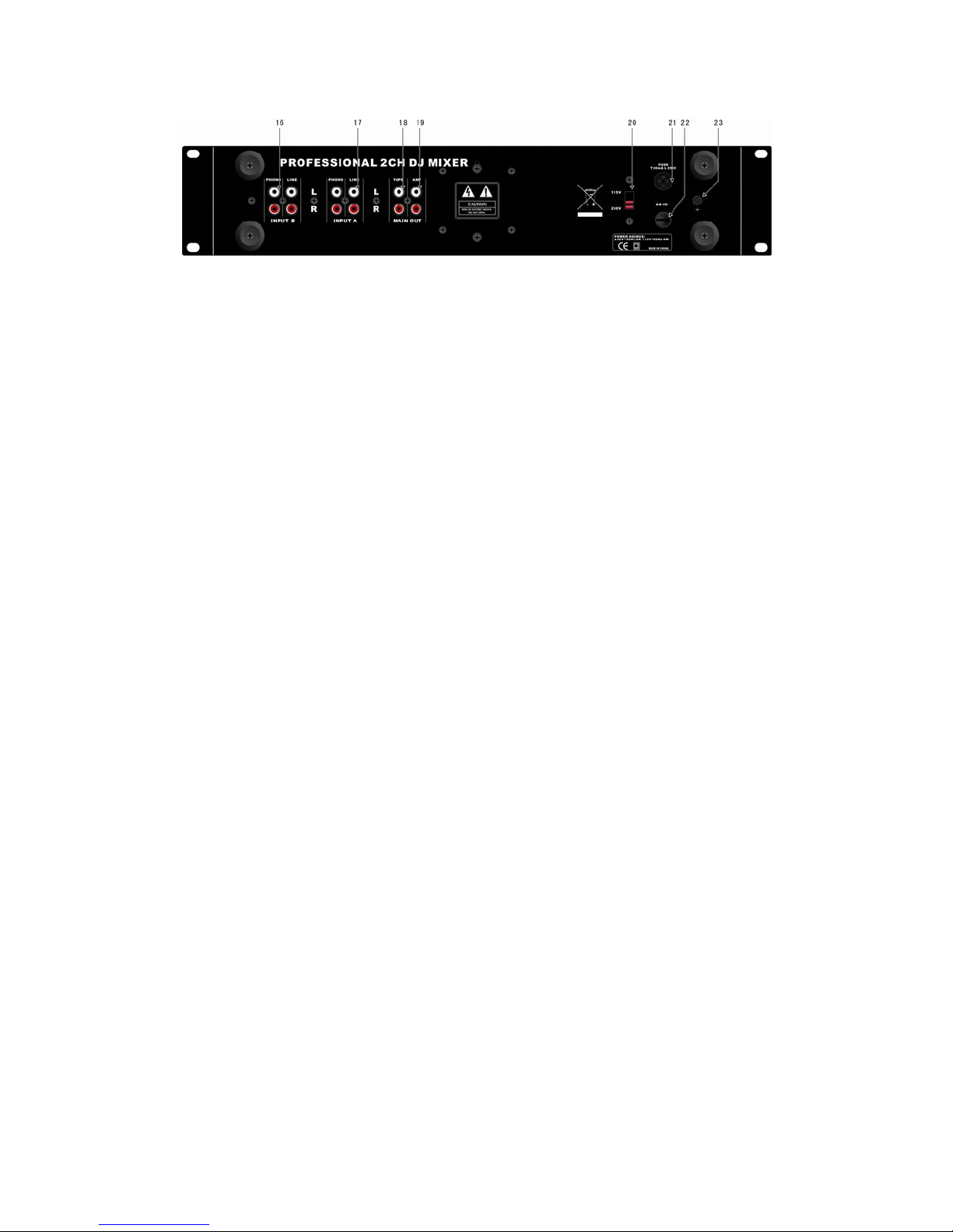
3. REAR PANEL
With the exception of MIC INPUT and HEADPONES, all of the unit’s audio
connections are located on the rear panel and suppl i ed as RCA connectors.
16. The PHONO inputs for channel 1 and 2 an d are only for turntable.
17. The LINE inputs may be used for connecting tape decks, CD or MD players.
18. The TAPE output enables you to record your performance by connecting a tape
deck, DAT recorder etc. Unlike the AMP output, the T APE level is fixed, so that
you have to adjust the input level on the recorder .
19. Use the AMP output to connect the unit to an amplifier. The level is controlled by
the MAIN knob.
In order to avoid power-up thumps, which can damage your loudspeakers,
please power up your amplifier last. There should be no signal present,
e.g. no music playing, when you turn on your amp. In addition, we
suggest that you set all volume-related controls to “zero” (down) before
powering up your system.
20. VOLTAGE SELECTOR. Used this selector to choose the correct Power supply,
(230V~50Hz or 115V~60Hz)
Before you connect the equipment to an AC outlet, please be sure that
the voltage displayed corresponds with your local AC voltage.
21. FUSE HOLDER. If you should need to replace the fuse, be sure to replace it
with one of the same type and value
To operate the unit at 230 V, you must install a fuse with T80mA. If operate
the unit at 115 V, you must install a fuse with T160mA
22. The power cable input
23. The GND connection is for grounding of a turnt able.
Page 7

4. SPECIFICATIONS
AUDIO INPUTS
Mic input ……………..…………………..…..…...53 dB gain, servo-balanced
Phono inputs 1 and 2 ……………..… ….40 dB gain @ 1kHz, unbalanced
Line inputs 1 and 2 ……………….……..…. 0 dB gain, unbalanced
AUDIO OUTPUTS
Main Out …………………………..…..max. +21 dBu @ +15 dBu (LINE IN)
Tape Out…………………………………………….………….typically 0 dBu
Headphones ………………….………………..typically 125mW @ 1% THD
EQUALIZER
Stereo Low…………………………………………..+ 12 dB/-32dB @ 50Hz
Stereo High…………………………………………+ 12 dB/-32dB @ 10kHz
GENERAL
Signal-to-noise ration (S/N) ………………………………………> 88dB
Crosstalk…………………………………………………………….> 67dB
Distortion (THD)………………………………………………….< 0.025%
Frequency response………………………………………..20Hz - 20kHz
Input gain adjustment………………………………………..-20dB - +9Db
POWER SUPPLY
Mains voltages………………………………………………..230V ~, 50Hz
Power consumption……………………………………………..max. 10 W
Fuse……………………………..…………200 – 240 V ~: T 80Ma 250V
DIMENSIONS AND WEIGHT
Dimensions (H x W x D)……………………………….. 482 x 88 x 115mm
Weight …………………………………………………………………..2.5kg
Page 8

NEW JERSEY SOUND CORP
Products are Distributed Exclusively by
Electrovision Ltd
ELECTROVISION Ltd
Lancots Lane
Sutton Oak
St Helens
Merseyside
WA9 3EX
WWW.ELECTROVISION.CO.UK
Tel: 01744 745000
Fax: 01744 745001
 Loading...