

Page 1

MOD-SIX
Nixie Clock System
Updating Instructions
August 2015
This manual provides instructions for updating the firmware of the
MOD-SIX Nixie Clock System firmware as well as a brief firmware
revision summary.
Revision/Update Information: This is a revised manual
Clock Firmware: V08-08
GPS Repeater-Next Firmware: V36
Keyfob Firmware: V14
http://www.badnixie.com
Page 2

26 August 2015
This document may be freely copied provided it is not modified. For permission to
distribute modified versions of this document, contact the author.
Apple, Mac, and Mac OS are registered trademarks of Apple, Inc.
FreeBSD is a registered trademark of The FreeBSD Foundation.
Linux is a registered trademark of Linus Torvalds.
Windows is a registered trademark of Microsoft.
CAUTION: This clock makes use of high voltages within the case. Use extreme care
when operating the clock with the cover removed.
The information in this document is subject to change without notice and should not
be construed as a commitment by the authors. The authors make no representations
or warranties with respect to the contents or function of this document and specifically
disclaim any implied warranties of merchantability or fitness for any particular purpose.
Copyright © 2012-2015 Terry Kennedy
Page 3

Preface
This manual provides instructions for performing firmware updates as
well as a brief firmware version summary for the MOD-SIX Nixie Clock
System.
Intended Audience
This manual is intended for all MOD-SIX Nixie Clock System owners.
Important Cautions
Hazardous voltages are present at some locations on the circuit boards
when the clock is operating. Avoid touching any components other than
the updating dongle while power is applied.
Never install or remove the updating dongle or the RF-Link mezzanine
board while power is applied.
Like all electronic devices, the clock system components can be damaged
by static electricity. When updating the firmware, always touch the
aluminum base plate first to discharge any static.
The tubes are extremely fragile and expensive. Take care to avoid
damaging them when removing and reinstalling the acrylic cover and
when updating the clock firmware.
iii
Page 4

1
Identifying the installed firmware
In order to determine if there is a newer version of firmware available for
any of your clock components, you will need to first determine the current
versions. This chapter provides instructions for identifying the firmware
version of each clock system component.
1.1 Identifying clock firmware
Unplug the power cable from the left rear of the clock. Wait a moment and
then plug it back in. As part of the clock’s startup messages, it will display
the firmware version as "Vxx-xx" where xx-xx is the current firmware
version.
1.2 Identifying GPS repeater firmware
Disconnect the power from the GPS repeater, either by unplugging the AC
adapter from the wall outlet or by unplugging the other end of the power
cord from the GPS repeater, whichever will give you a better view of the
clock. Wait a few moments and reconnect the GPS repeater’s power. The
clock display will show a series of messages, one of which will be "NEX xx"
where xx indicates the GPS repeater’s current firmware version.
Note: The clock must be running firmware V08-01 or newer AND the GPS
repeater must be a next-generation model (V31 or newer) in order
to display this information. Failure to display messages from the
repeater does not identify which of the clock, GPS repeater, or
both is out of date.
Note: The repeater firmware also displays the version on the repeater’s
IND LED at power-on. For example, three red blinks followed by
six green blinks would indicate firmware V36.
1.3 Identifying keyfob firmware
Press and hold both the up and down buttons on the keyfob simultaneously
until the clock reports the keyfob version. This will happen within 10
seconds. The clock will display a message of the form "F# x-x" where #
indicates the keyfob’s current address (0-7) and x-x indicates the keyfob’s
firmware version.
Note: The clock must be running firmware V08-01 or newer in order to
perform this function.
Note: The same up + down procedure will also display the keyfob version
number on the keyfob LED. For example, one red blink followed
by four green blinks would indicate version V14.
1–1
Page 5
2
Firmware updating procedures
2.1 Clock updating procedure
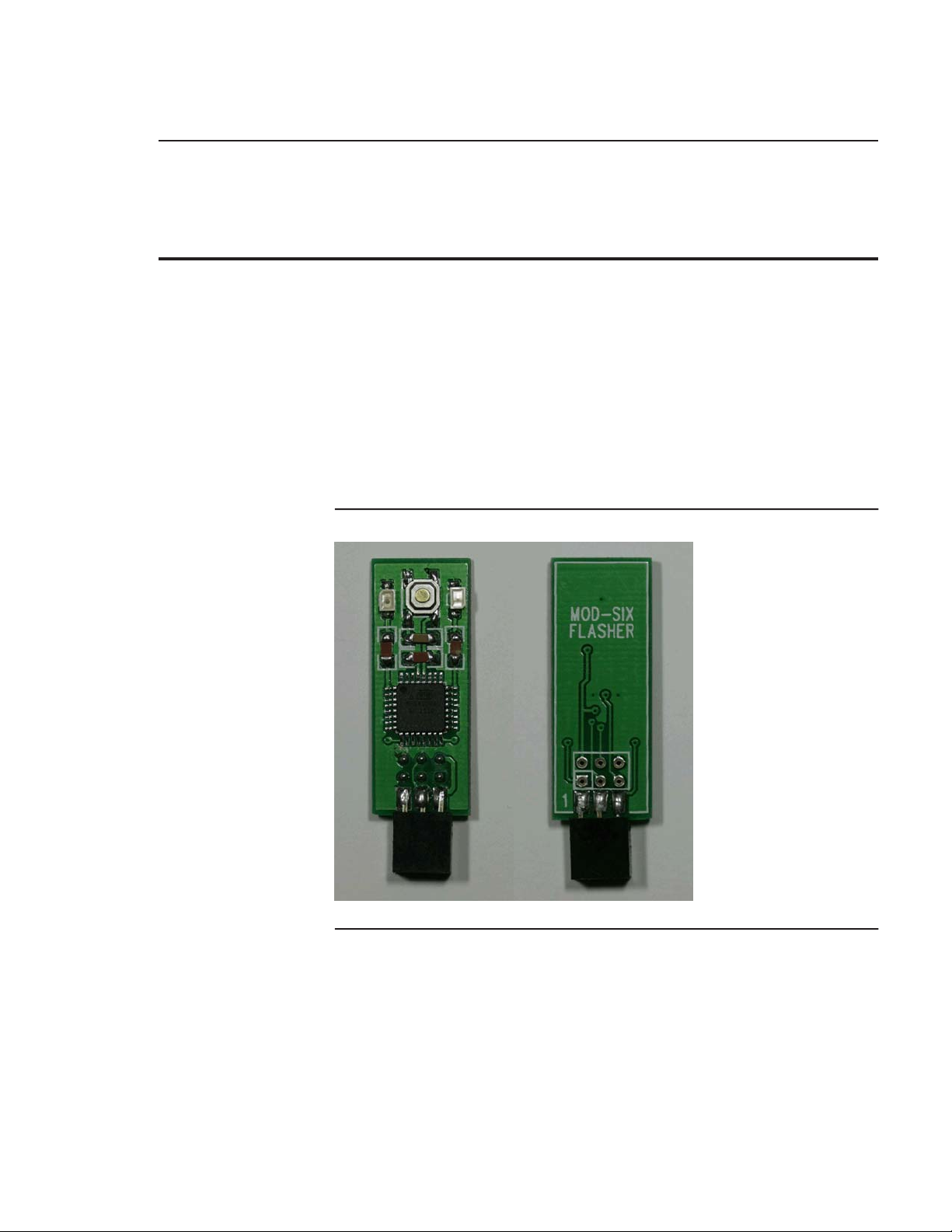
Clock firmware updates are performed with a small updating dongle. The
dongle installs the new firmware onto the clock CPU and is removed once
the update is completed.
Note: Depending on your current clock firmware version, you may or
may not receive a clock updating dongle.
Note: The dongle checks to make sure it contains appropriate firmware
for the device being updated and will not install the update if it is
for the wrong device.
Figure 2–1 Updating Dongle (front and back views)
Note: You may want to write down your clock configuration settings
before proceeding, as the update process resets the clock to default
values.
To perform the update, disconnect the power cord from the clock. Remove
the acrylic cover (you may want to use cotton gloves or some similar
method to avoid getting fingerprints on the cover) and set it aside. Locate
the programming connector on the CPU board, labeled "ISP J4". Note that
if you have a GEN I CPU (labeled "CPU 1.0") with an RF-Link mezzanine
2–1
Page 6
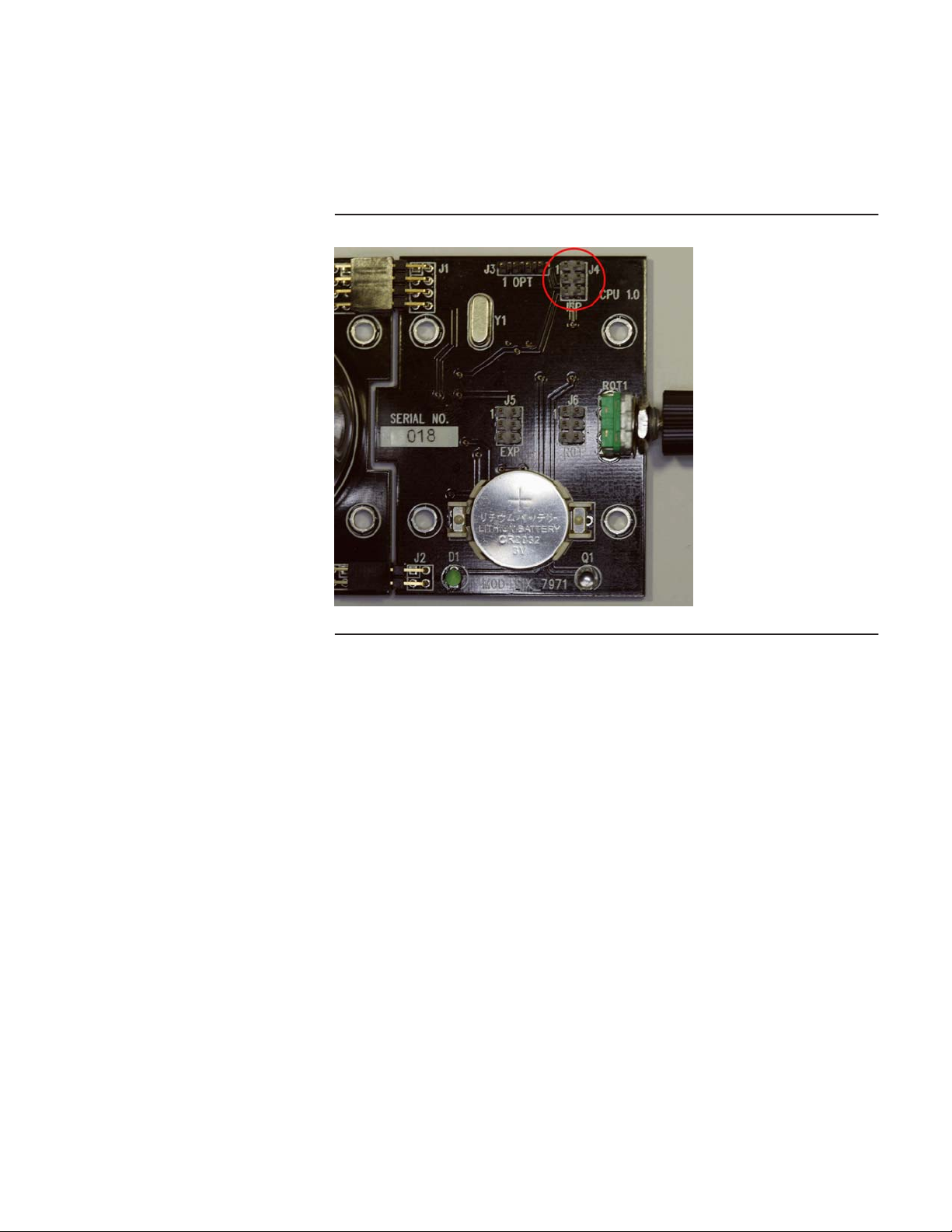
Firmware updating procedures
board installed, you will need to remove the mezzanine board in order to
access the ISP connector.
Figure 2–2 Location of ISP connector on CPU
Note: The above picture shows a GEN I CPU. While the layout of the
GEN II CPU is somewhat different, the ISP connector is in the
same location and orientation.
Install the updating dongle on the CPU with the dongle components facing
away from the tubes. Make sure that all 6 pins on the dongle are on the
matching pins on the CPU, not offset by one pin.
Note: The clock generates and uses high voltages to operate the tubes.
Use caution to not touch any clock components other than the
updating dongle when performing the update procedure.
2–2
Page 7
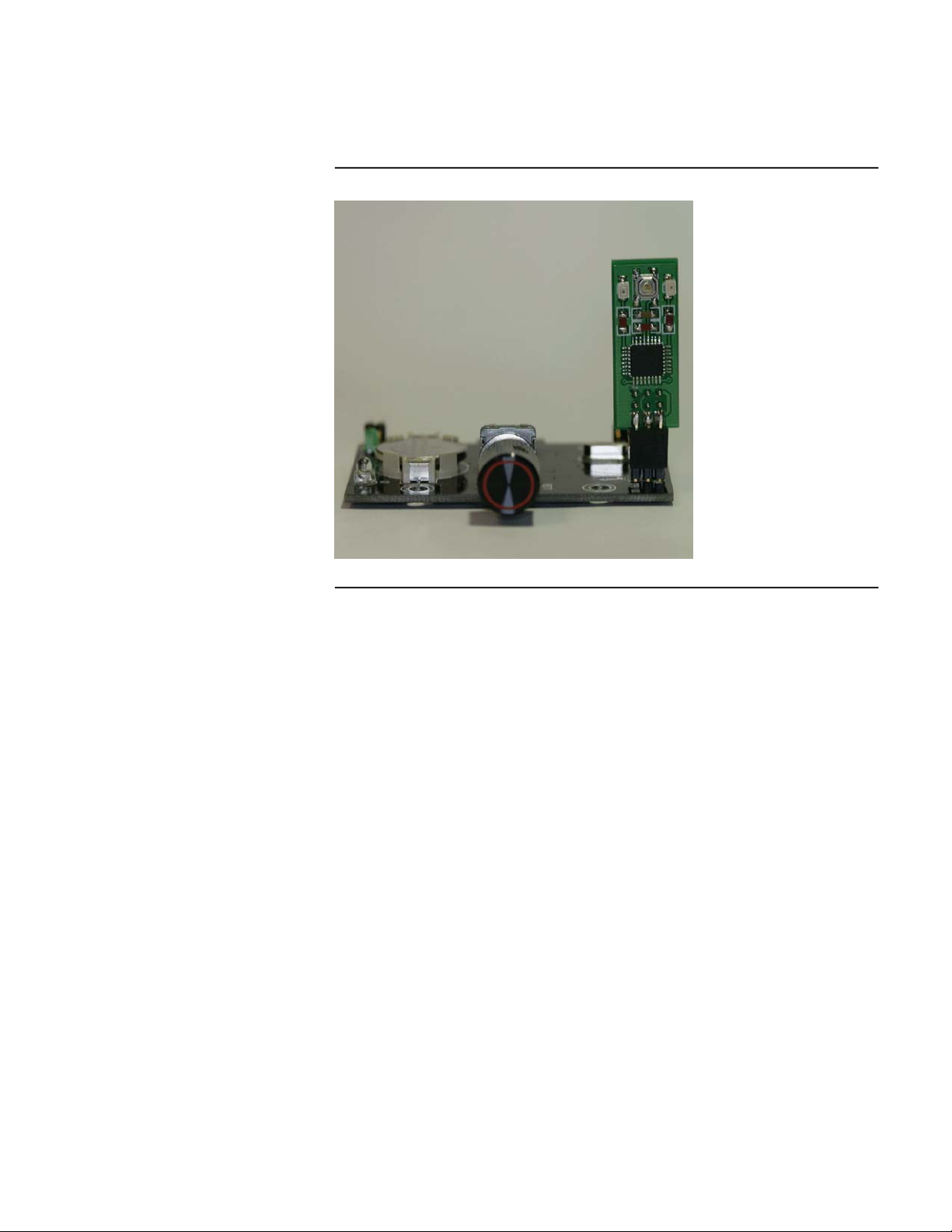
Figure 2–3 Dongle installed on CPU
Firmware updating procedures
Apply power to the clock and wait for it to proceed through its normal
startup. If the clock does not power on and display the normal startup
messages, immediately disconnect the power and check your installation of
the updating dongle.
Press the button on the top center of the updating dongle. It is rather
small, and you may have trouble pressing it if you have large fingers.
There should be an obvious tactile "pop" when it is successfully pressed.
The red and green LEDs on the dongle will light while updating is in
progress. This normally completes within a few seconds. After the update
completes, the green LED will remain lit to show a successful update and
the clock will reset and display the new firmware version. If the red LED
is lit instead, the firmware update was unsuccessful and you should press
the button again to repeat the update procedure.
Note: During the updating process, the tubes may go blank or freeze
while displaying a message. This display may be brighter or
dimmer than normal operation and does not indicate a problem
with the update process.
Once updating is complete, disconnect power from the clock and remove
the updating dongle. If you removed the RF-Link mezzanine board,
reinstall it, being careful to align all the connectors properly. Place the
dongle back into its antistatic bag and reinstall the acrylic cover on the
clock.
Apply power to the clock and set your desired configuration options. You
may wish to review the new features in the latest User’s Guide to see if
there are any new options you’d like to explore.
2–3
Page 8

Firmware updating procedures
2.1.1 Return of the updating dongle
Once you have confirmed that the firmware has been updated and all
components are operating normally, please email badnixie@badnixie.com
for the address to return the dongle to.
Note: A single dongle and its packaging can be mailed in a regular
envelope and should be under 1 ounce.
Note: Returning the dongle lets us send it to another clock owner and
keep costs down.
2.2 GPS repeater updating procedure
The GPS repeater firmware and lexicon (random word dictionary) may be
updated using a Windows® PC, an Apple® Mac® (running OS X®), or any
other system that supports USB Mass Storage devices such as systems
running FreeBSD® or Linux®.
You will need the following in order to update the GPS repeater firmware:
• A computer of one of the types shown above and general familiarity
with command line operations on that computer
• GPS repeater
• Updated firmware and lex_make utility (available from
http://www.badnixie.com/MOD-SIX_Info_Page.html)
• USB cable with mini-B (not micro-B) connector on one end and a
connector appropriate for your computer (normally full-size A, but this
can vary) on the other end
The following figure shows the top of the USB repeater.
2–4
Page 9

Figure 2–4 GPS repeater top view
Firmware updating procedures
Unplug the USB power cable from the GPS repeater’s USB connector
(shown on the right side of the figure above). If necessary, unscrew the
GPS antenna connector from the repeater (left side, lower). You may leave
the radio antenna attached. Attach one end of the USB cable to your
computer and while pressing and holding the button (top side, toward left)
on the repeater, plug the other end of the USB cable into the mini-USB
connector on the repeater.
At this point, no LEDs should be lit on the GPS repeater. If any LEDs are
lit, it indicates that the repeater is not in updating mode. Disconnect the
USB cable from the repeater, ensure that the button is pressed firmly, and
repeat the operation.
Once the GPS repeater powers up in updating mode, your computer may
or may not display a "Found new hardware" (or similar) message. The
computer should automatically install any necessary driver software. If
you are prompted to provide driver software, allow the computer to search
the appropriate places for it. For example, Windows Update when using a
Windows computer.
Note: The GPS repeater (when in updating mode) acts as a standard
USB Mass Storage device and no unusual drivers are needed. The
same drivers that handle (for example) USB flash drives will work
with the GPS repeater.
If the GPS repeater does not illuminate any LEDs but the computer does
not detect it, you may have a bad USB cable or perhaps the USB port
you are using on the computer has been disabled. Some systems allow
disabling groups of USB ports (although this is normally only done in
2–5
Page 10

Firmware updating procedures
corporate environments). Try a port in a different group (for example, try
a port on the back of the computer if you were using one on the front). You
can also try using a different USB cable and / or a different computer.
Once you have the GPS repeater in updating mode and detected by the
computer with any necessary drivers installed, it should appear as an
additional disk drive. The method used to display this new disk drive
will vary depending on the operating system used, but the computer will
normally display some type of message indicating the name that was
assigned, and / or add a new icon to the desktop. The "volume label" of
the drive will be CRP DISABLD and the type of drive (possibly not shown)
will be LPC1XXX IFLASH.
2.2.1 The firmware update file
One or more standard firmware files are provided in the update package
(available from http://www.badnixie.com/MOD-SIX_Info_Page.html). You
can use either one of the pre-built firmware files, you can modify the
supplied lexicons and build your own firmware file, or you can create
entirely new lexicons from scratch. Building customized lexicons is covered
in Appendix A. The examples in this chapter assume you are using the
provided firmware file named RPTR-NEX_V36_LEX-BASIC.bin, although
the procedure is the same with a customized lexicon.
2.2.2 Updating procedure for Microsoft Windows
Open a command prompt window on the computer. This is normally done
with the Start / Run menu sequence followed by typing cmd and pressing
Enter, but can vary depending on the version of Windows installed. This
should open a new window on the desktop. Use the mouse to click on that
window to start using the command line. In the following example, we will
assume that the drive letter assigned to the GPS repeater is I: although
this will vary depending on the computer being used. We will also assume
that the new firmware file is located in the tmp directory on drive C: and
is named RPTR-NEX_V36_LEX-BASIC.bin.
• Type dir i: and press the Enter key to make sure you are on the
correct drive
• Type del i:firmware.bin and press Enter to delete the old firmware file
• Type xcopy c:\tmp\RPTR-NEX_V36_LEX-BASIC.bin i:\ and press
Enter to copy the file to the GPS repeater
Note: If you receive an "Insufficient disk space" or similar error it
means that you did not delete the firmware file in the previous
step, or (unlikely) that the firmware file you are attempting to
copy is damaged or too large.
• Type dir i: and press Enter to verify that the file was copied to the
repeater
2–6
Page 11

Firmware updating procedures
C:\tmp>dir i:
Volume in drive I is CRP DISABLD
Directory of I:\
02/06/2009 10:10 AM 131,072 firmware.bin
C:\tmp>del i:firmware.bin
C:\tmp>xcopy c:\tmp\RPTR-NEX_V36_LEX-BASIC.bin i:\
C:\tmp\RPTR-NEX_V36_LEX-BASIC.bin
1 File(s) copied
C:\tmp>dir i:
Volume in drive I is CRP DISABLD
Directory of I:\
08/24/2015 08:23 AM 103,934 RPTR-NEX_V36_LEX-BASIC.bin
Note: If you disconnect the repeater from the computer and reconnect
it, the name of the firmware file as well as its size and date/time
will revert to firmware.bin, etc. This is to be expected.
1 File(s) 131,072 bytes
0 Dir(s) 0 bytes free
1 File(s) 103,934 bytes
0 Dir(s) 26,624 bytes free
You should now close the terminal window. Use one of the supported
Windows methods to "eject" the GPS repeater’s drive letter. This can be
done by clicking on the "Safely remove hardware" icon in the tray and then
clicking on the drive letter associated with the GPS repeater’s device. The
remove hardware menu will normally also show the volume label (CRP
DISABLD). You may also perform an eject function by double-clicking
on the Computer (or My Computer in some versions of Windows) icon,
normally near the top left of the Windows desktop. Then right-click on
the drive letter of the GPS repeater and select Eject from the drop-down
menu.
Note: If the computer responds with some form of "Drive in use" error
message, it is possible that you did not close the command line
window you used to perform the firmware update or other activity
on the computer (such as an anti-virus program) may be using the
drive. In cases where Windows refuses to "let go" of the drive and
allow you to eject it, you may just wait several minutes for any I/O
operations to complete and then just unplug the USB cable from
the GPS repeater.
2.2.3 Updating procedure for Mac OS X
After you plugged the USB cable into the GPS repeater as described
above, you should have an icon on your desktop labeled CRP DISABLD.
If not, perform the checks described above to make sure the button on the
repeater was pressed and that the USB cable and computer’s USB port
are working.
• Open the Terminal program, which is located in Utilities
• Click on the CRP DISABLD icon on the desktop to view the file(s) on
the drive
• Type the command rm and press the spacebar
2–7
Page 12

Firmware updating procedures
• Drag and drop the old repeater firmware file from the CRP DISABLED
drive onto the terminal window
• Its path will be added to the end of the rm command, for example:
MyComputer:~ myname$ rm /Volumes/CRP\ DISABLD/firmware.bin
• Confirm that the command line is correct and refers to the proper file
and the GPS repeater drive, then press Return
Note: Once a file is deleted with the rm command, the file is truly
deleted and not recoverable. Make sure you are deleting the
correct file!
• Type the command cp -av and press the spacebar
• Locate the folder containing the new firmware file (we will assume it
is located on the desktop in a folder named NEWFILE)
• Drag and drop the NEWFILE folder from the desktop into the terminal
window to add the full path to the command line
• Press the Delete key once to remove the trailing space
• Type /*
• At this point the command should look similar to this:
MyComputer:~ myname$ cp -av /Users/myname/Desktop/NEWFILE/*
• Press the spacebar
• Drag and drop the CRP DISABLD folder from the desktop onto the
terminal window
• Type /
• The command line should now look similar to this:
MyComputer:~ myname$ cp -av /Users/myname/Desktop/NEWFILE/*
,
!
/Volumes/CRP\ DISABLD/
Note: The
• After confirming that your command line looks like the above, press
• The computer should display something similar to this:
• Right-click on the CRP DISABLD icon on the desktop and select Eject
,
!
symbol indicates that this is part of the previous line,
but split to fit the format of this manual.
Return to copy the new firmware file to the repeater
/Users/myname/Desktop/NEWFILE/RPTR-NEX_V36_LEX-BASIC.bin
,
!
-> /Volumes/CRP DISABLD/RPTR-NEX_V36_LEX-BASIC.bin
to "eject" the GPS repeater from the computer
2–8
Note: If you disconnect the repeater from the computer and reconnect
it, the name of the firmware file as well as its size and date/time
will revert to firmware.bin, etc. This is to be expected.
Note: The above procedure MUST be used on Mac OS X systems. A
simple drag-and-drop operation will NOT work. This is due to
the Mac’s use of resource forks - a drag-and-drop copy will cause
the repeater to try to load the resource fork instead of the actual
firmware file.
Page 13

Firmware updating procedures
2.2.4 Updating procedure for other operating systems
It is not possible to enumerate methods for all of the possible operating
systems that users may have. Review the Windows and Mac OS X
procedures above for some background information. You will then need to
perform the following general steps, in order:
• Mount the GPS repeater device
• Perform a directory operation on the device to make sure you are
accessing the proper device
• Delete the firmware.bin file from the device
• Copy the new firmware file to the device
• Perform another directory operation to confirm that the new firmware
file was properly copied
• Dismount the device
2.2.5 Reinstall repeater on clock
Unplug the GPS repeater from the computer’s USB cable. Return the
repeater to its previous location and reconnect the GPS antenna cable (if
previously disconnected). The antenna cable only needs to be tightened
finger tight.
Plug the USB power cable into the GPS repeater. The repeater should
power up and display its firmware version via blink codes. For example,
three red blinks followed by six green blinks would indicate firmware V36.
The repeater will then send various pieces of information to the clock,
which will display them. The following is a list of typical display items in
order.
NEX 36
CH 77
BAR/RH
LEXCON
MYWRDS
21083
WORDS
This example shows GPS repeater firmware V36, radio channel 77,
optional installed barometric pressure and relative humidity sensors,
and a lexicon (random word dictionary) named MYWRDS ("my words")
which contains 21,083 words.
Note: Updating the repeater firmware does not change any previously
configured LNKMNU / RFCHAN and LNKMNU / BAUD settings
(in other words, you do not need to re-pair the repeater to the
clock). The LED display mode is also unchanged from the previous
setting.
2–9
Page 14

Firmware updating procedures
2.3 Keyfob updating procedure
Due to the small size of the keyfob circuit board and enclosure, it is
not practical for most users to upgrade the keyfob firmware. Firmware
updates will be handled by a "return for update" procedure if it becomes
necessary to update the keyfob firmware.
2–10
Page 15

3
Version history
Note: Gaps in version numbers indicate unreleased development
versions.
3.1 Clock version history
• V06-06 - Version shipped with original GEN I clocks
• V07-07 - Version shipped with GEN II clock kits
• V07-09 - Version shipped with assembled GEN II clocks
• V07-53 - Version shipped with GEN IIv7 clocks
• V08-08 - Version shipped with GEN IIv8 (SLW) clocks, latest version
3.2 GPS repeater version history
• V10 - Version shipped with GEN II clocks and GEN I upgrade kits
• V26 - Version shipped with GEN IIv7 clocks
• V27 - Version shipped as an update for GEN IIv7 clocks
• V36 - Version shipped with GEN IIv8 (SLW) clocks with word
dictionary, latest version
3.3 Keyfob version history
• V12 - Version for prototype (Sparkfun) hardware
• V14 - Version shipped with GEN IIv8 (SLW) clocks, latest version
3–1
Page 16

A
Building custom lexicons
A.1 Lexicon build procedure
A pre-built version of the lex_make utility for Windows systems is provided
as part of the firmware update kit. The source code is provided and should
compile and run on any system with a modern C compiler and runtime
library.
Note: Normally you will use the pre-built lex_make utility. The source
code is provided in case you do not have a Windows system
available. Instructions for compiling the utility are outside the
scope of this document; refer to your operating system or compiler
documentation for more information.
The lex_make utility reads a configuration file and creates a custom
firmware image based on the supplied configuration. Here is a sample
config file named lex_basic.cfg:
rptr-nex_3.6.blob
RPTR-NEX_V36_LEX-BASIC.bin
BASIC
words/flw_dirty.txt
words/slw_dirty.txt
words/flw_basic.txt
words/slw_basic.txt
The first line contains the filename of the actual GPS repeater code "blob".
The second line is the name of the firmware file to create. The third line is
the display name of the lexicon which will be displayed on the clock when
the GPS repeater powers up or is paired to the clock. The following lines,
which can be as few as one or as many as you’d like, list the filenames
of lexicons to be incorporated into the firmware. This example includes
both the 4- and 6-letter "dirty" lexicons as well as the 4- and 6-letter basic
lexicons. Additional lexicons can be found in the "words" subdirectory and
example config files which use them are also provided.
The lexicons are stored in a special compressed format in order to increase
the number of words which will fit in the repeater. The lex_make utility
attempts to verify that the created firmware image will be small enough
to fit in the repeater, however it does not guarantee that this is the case.
If you add a very large number of words, you may exceed the storage
capacity of the GPS repeater.
The following example shows the procedure to create firmware with the
BASIC lexicon:
C:\tmp>dir/s
Volume in drive C has no label.
Volume Serial Number is 7A06-DFCD
Directory of C:\tmp
A–1
Page 17

Building custom lexicons
08/25/2015 01:34 AM <DIR> .
08/25/2015 01:34 AM <DIR> ..
08/25/2015 01:34 AM <DIR> code_source
08/24/2015 08:22 AM 138 lex_basic.cfg
08/24/2015 08:22 AM 103 lex_clean_only.cfg
08/24/2015 08:22 AM 103 lex_dirty_only.cfg
08/24/2015 08:22 AM 140 lex_large.cfg
07/29/2015 04:14 PM 118,796 lex_make.exe
08/24/2015 08:37 AM 2,835 readme.txt
07/27/2015 10:29 AM 28,696 rptr-nex_3.6.blob
08/24/2015 08:23 AM 103,934 RPTR-NEX_V36_LEX-BASIC.bin
08/23/2015 10:31 AM 24 windows users can drop cfg file here.bat
08/25/2015 01:34 AM <DIR> words
Directory of C:\tmp\code_source
08/25/2015 01:34 AM <DIR> .
08/25/2015 01:34 AM <DIR> ..
07/29/2015 04:14 PM 9,797 lex_make.c
Directory of C:\tmp\words
08/25/2015 01:34 AM <DIR> .
08/25/2015 01:34 AM <DIR> ..
07/27/2015 10:07 AM 20,395 flw_basic.txt
07/29/2015 10:06 AM 145 flw_dirty.txt
03/15/2014 12:43 PM 27,051 flw_large.txt
07/27/2015 10:10 AM 112,058 slw_basic.txt
07/29/2015 10:50 AM 138 slw_dirty.txt
07/06/2015 09:43 AM 126,164 slw_large.txt
C:\tmp>type lex_basic.cfg
rptr-nex_3.6.blob
RPTR-NEX_V36_LEX-BASIC.bin
BASIC
words/flw_dirty.txt
words/slw_dirty.txt
words/flw_basic.txt
words/slw_basic.txt
C:\tmp>lex_make.exe lex_basic.cfg
LEXICON MAKE UTIL 1.4, August 2015
Processed "words/flw_dirty.txt", 25 total words were processed from text file.
Processed "words/slw_dirty.txt", 16 total words were processed from text file.
Processed "words/flw_basic.txt", 4022 total words were processed from text file.
Processed "words/slw_basic.txt", 15783 total words were processed from text file.
Total lines processed = 1872
Total regular four letter words = 4022
Total regular six letter words = 15783
Total four letter dirty words = 25
Total six letter dirty words = 16
Total words = 19846
Now generating output bin file.
Lexicon "BASIC" output to file:"RPTR-NEX_V36_LEX-BASIC.bin".
Looks good to me. 103934 bytes were written to file.
9 File(s) 254,769 bytes
1 File(s) 9,797 bytes
6 File(s) 285,951 bytes
Total Files Listed:
16 File(s) 550,517 bytes
8 Dir(s) 102,133,772,288 bytes free
A–2
Note: The above example assumes the Windows command-line
environment. Operation will be similar under other operating
systems.
Page 18

A.2 Lexicon file format
The word files used by the lex_make utility have a simple format: 4 or
6 letters followed by either a space or the end of a line. The following
sample shows the first few lines of the flw_basic.txt file:
aahs aals abas abba abbe abed abet able ably abos abri abut abye abys
aced aces ache achy acid acme acne acre acta acts acyl adds adit ados
adze aeon aero aery afar agar agas aged agee ager ages agha agin agio
Similarly, this sample shows the first few lines of the slw_basic.txt file:
aahing aaliis aarrgh abacas abacus abakas abamps abased abaser abases
abasia abated abater abates abatis abator abayas abbacy abbess abbeys
abbots abduce abduct abeles abelia abhors abided abider abides abject
To mark a word as "dirty", simply capitalize one or more letters of the
word. For example, to mark the word abacus as dirty, simply change the
first line of the above sample to:
aahing aaliis aarrgh abacas abaCus abakas abamps abased abaser abases
You could use ABACUS, Abacus, aBaCuS or any other combination of
capital and lowercase letters - as long as there is at least one capital letter,
the word will be marked as dirty.
Building custom lexicons
Note: There is no reason (other than convenience) that the dirty word
lists are stored in separate files. You can merge them into a single
file if you prefer.
A.2.1 Suggestions for managing custom lexicons
We suggest that you create a new .cfg file using one of the existing ones
as a template and that you also add your words to a separate lexicon
file. Future updates to the GPS repeater firmware utility may overwrite
the existing configuration and lexicon files. Using your own names for
these files will ensure that your changes are preserved across updates.
For example, you could create a file named lex_mywords.cfg with these
contents:
rptr-nex_3.6.blob
RPTR-NEX_V36_LEX-MYWRDS.bin
MYWRDS
words/flw_dirty.txt
words/slw_dirty.txt
words/flw_basic.txt
words/slw_basic.txt
words/my_words.txt
You would then add your words to the words/my_words.txt file.
You may add foreign words to the lexicon files if you so desire. However,
those words should be modified (if necessary) to contain only the English
letters A through Z as the tubes in the clock can only display English
letters.
Note: When you receive a new firmware update package, you should
check to see if the version of the code blob has changed, and make
the corresponding change to your .cfg file (the first and second
A–3
Page 19

Building custom lexicons
lines). This ensures that your custom firmware has the lastest GPS
repeater code included.
A–4
Page 20

B
Advanced updating techniques
The above clock updating procedure presumes that you are using the
supplied updating dongle when updating the firmware. Firmware
updates are also available (upon request) as .hex files for those who
have their own programming capability. In this case, the firmware is
directly installed onto the clock without using an updating dongle as
an intermediary. As a minimum, you will need updating software such
as AVRDUDE (http://www.nongnu.org/avrdude) or eXtreme Burner
(http://extremeelectronics.co.in/software/BurnerAVR) as well as a
compatible programmer such as the USBasp (http://www.fischl.de/usbasp).
The choice of programming hardware and software is up to you. However,
not all combinations (in fact, very few) have been tested by us so some
experimentation may be needed. Here are some pointers which may be
useful:
• The CPU on the clock is an ATMEGA168A and should be programmed
at 5V.
• Many USBasp devices come with a 10-pin programming connector. In
that case, you will need a 10-pin to 6-pin adapter for programming the
MOD-SIX clock.
• On some programmers / adapters, the 6-pin connector has a large
keying tab which may interfere with seating the adapter on the ISP
connector.
• The dongle’s checks for appropriate firmware type do not apply when
directly programming the MOD-SIX clock. Therefore, it is definitely
possible to flash something that doesn’t work. As long as you do NOT
reprogram the fuses, you should be able to recover by flashing a valid
firmware image.
• If you are at all uncertain about the correct orientation / pinout of the
ISP connectors on the clock, refer to the schematic and board artwork
package provided with the clock.
B–1
 Loading...