

Page 1
Assembly Manual Miniature USB powered Nixie Clocks • Mainboard Rev.11-2013
Congratulations for purchasing this Nixie clock kit “Lars“ or “Laura”.
For successful assembly of this kit please read the following helpful hints.
• This kit is designed for someone who has advanced experience with assembling electronics.
• If you believe that the kit is too complicated for your skill level please do not try to assemble it - this
generally ends up with a device that is not repairable and results in you being very frustrated.
Please contact the provider and they can offer you other options that will end in a more fulfilling
result!
• Take your time - this kit should take 2 hours to complete if uninterrupted. Assembling the kit in a
hurry will lead to frustration and troubleshooting takes three times as long.
• Ensure your work area is well lit (daylight preferred) and clean.
• Electronic tools, such as pliers, small side-cutters or tweezers will be handy. You will also need a
T10 (Torx) Allen screwdriver for the housing assembly.
• A soldering iron station with a 1 mm round tip (maximum) and a 0.5 mm (maximum) fine electronic
solder (lead-free) is required. For lead-free solder we’ve had good experience with type Iso-Core
EL Sn95,5 Ag3,8 Cu0,7 with 0,5 mm Ø and 3,5% Flux from Felder Löttechnik and a 400°C soldering
tip temperature.
• For the intermediary function test you need a multimeter with at least 200 VDC range.
• A loupe (magnifying glass) to read the small device markings is often helpful.
• Assemble the board in the order as stated in the instructions - this has been proven and will
minimise mistakes.
• It is assumed that you understand that semiconductors (diodes, ICs, transistors) or electrolytic
capacitors are polarized components. Appropriate markings are silk-screened on the PCB and
shown on the board schematic.
Together with this construction guide there are some other usefull documents for
download
• The owners manual for this Nixie clock kit
• The owners manual for the BR-355 wired or “Wireless GPS Connection” system
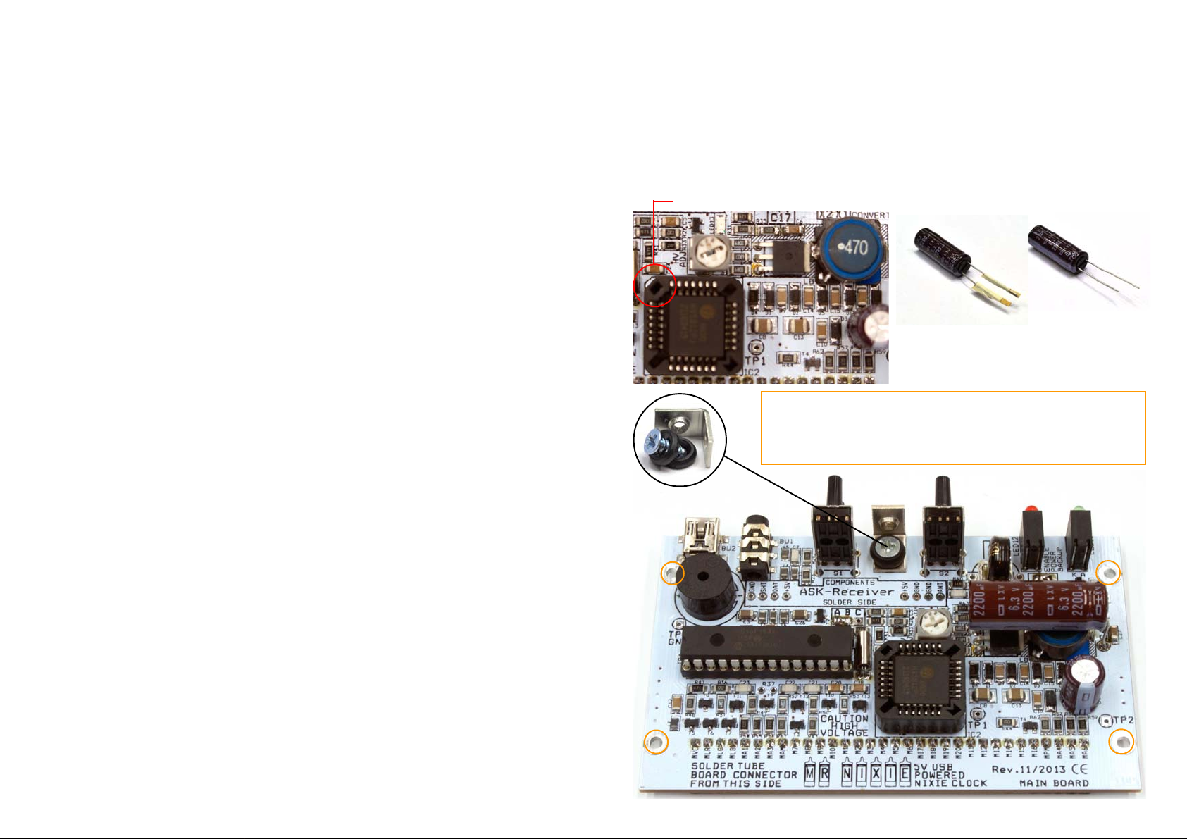
Start with soldering the 32-pol. female header, fitted from the solder (!) side.
Following fit and solder both 28-pol. IC sockets (pay attention for the notches as shown on the silk
screen, the crystal, the potentiometer, the Super Capacitor and the buzzer. The polarity marking on the
buzzer is negligable but keep care for the correct allignment of the Super Cap (arrows on the part
package and the silk screen). Do not insert the ICs at this stage !
Next solder the 47uH shielded inductor, than bend the leads of the RFD3055L MosFet and solder them.
Take special care as this is an ESD device, so it is a good idea before handling this part that you decharge yourself on a metallic part of your desktop. The heatsink can have contact to the left hand’s
inductor pad; this doesn’t matter at all. Finally add the remaining parts like the 2u2 / 350V capacitor , both
dual LEDs (take care for the colour), both dual switches and the mounting bracket.
Notch on socket and HV5812
Finally cut and remove the tape from the 2.200µF
capacitor. Please do not simple cut the wires at
the top of the tape as the remaining lenght will be
too short.
The following task must only be done when assembling a Laura
Nixie clock
Pick up the 4 x M3 x 8 self tapping screws and the 4 x 3 mm plastic spacers
and threat them to the drilling holes at the edges of the main board. The
spacers are a self fixing type.
Safety precautions:
During assembly, operation, measurements and maintenance extra precautions must be taken. The
generated high voltage of 160 V is dangerous. Assemble the circuit at your own risk.
The clock’s functionality cannot be guaranteed when assembled by the customer.
No responsibility can be taken for any personal claims and damages during assembly and
commission, especially for damages based on insufficient technical knowledge.
The Nixie clock may only be operated in a solid and moisture-proof enclosure.
The person who completes the kit and assembles this board into an enclosure for operation is
considered by the German directive VDE 0869 as a manufacturer and is required to indicate their
name and address including all documents when selling the clock.
Ready-to-go devices, which are assembled from kits, are counted as a safety-related industrial
made product.
Okay, and now, Ladies and Gentlemen – start your soldering iron...
As you might notice, most of the electrical parts are just pre-assembled and soldered.
However, we recommend to check these SMT assembly for assembly faults and cold solder pads
before assembling the through hole components.
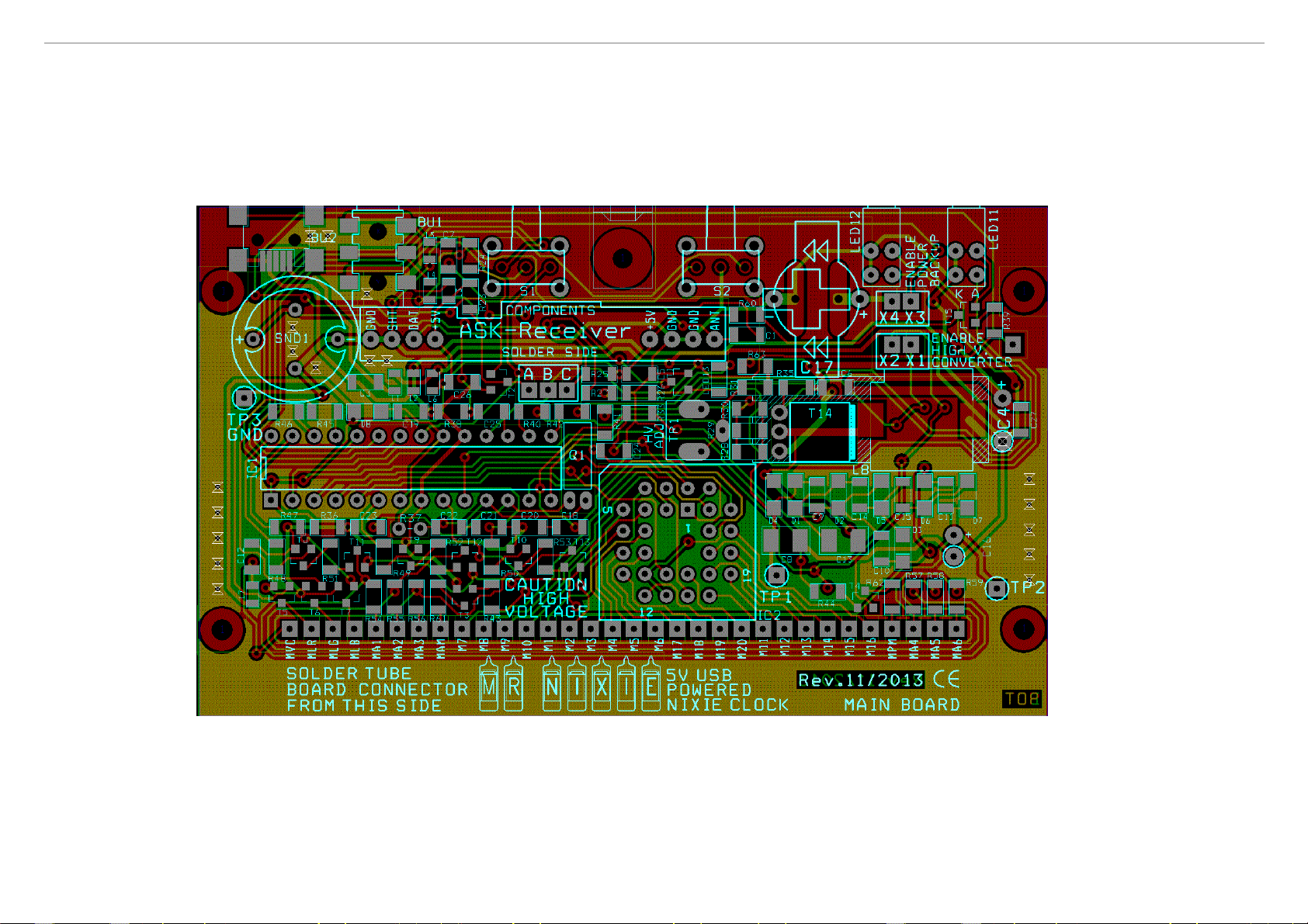
You’ll find at the end of the manual a detailed assembly silk screen for reference.
red
yellow
green
green
Page 2
Assembly Manual Miniature USB powered Nixie Clocks • Mainboard Rev.11-2013
Now connect the PCB to an USB power supply and check if something strange will happen; e.g. a
parts runs hot. If everything is allright we will do follwing some voltage checkings:
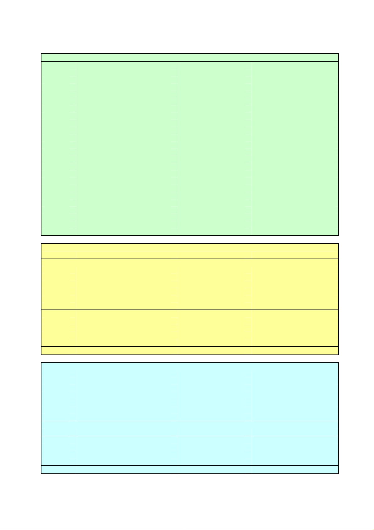
Please check the voltages on the PIC’s socket pins with a multimeter. Put the negative probe
(black) on TP3; left hand from the buzzer. Put the positive probe (red) on the socket pins.
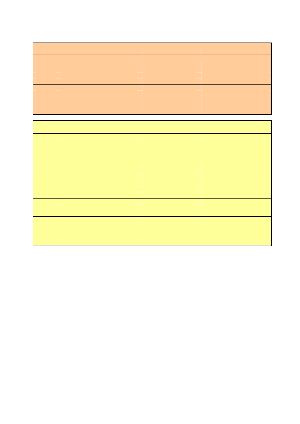
Measured Voltages
red = ca. 5 V • blue = 0...3 V • amber = ca. 0,3 V • green = ca. 0...-2 V • black = 0 V
Pin 1 • Pin 2 • Pin 3 • Pin 4 • Pin 5 • Pin 6 • Pin 7 • Pin 8 • Pin 9 • Pin 10 • Pin 11 • Pin 12 • Pin 13
Pin 14 • Pin 15 • Pin 16 • Pin 17 • Pin 18 • Pin 19 • Pin 20 • Pin 21 • Pin 22 • Pin 23 • Pin 24
Pin 25 • Pin 26 • Pin 27 • Pin 28
Check following the voltages on the other testpoints: TP1 (around 4.8 V) • TP2 (around 4.5 V)
Please do not proceed until all voltages are within their range and check for the fault.
If everything is ok, unplug the clock from the power supply.
Solder now jumper ENABLE HIGH V. CONVERTER X1/X2, direct above the inductor and insert ONLY
(!) the PIC, but not the HV5812 driver. Keep care for correct orientation. Turn on the clock again.
Caution! Now the HV converter is working. Please check again, if something strange happens;
e.g. if a part will run hot. Pick up now a screwdriver and do again a measurement of the voltage on
TP1 It should be in the range of 40 V. Adjust now the voltage with the potentiometer to 41 V.
Do following a voltage check on TP2. It should be in the range of 165 V.
Push now button SET. The clock must make a short bleep.
Unplug the clock again from power and wait 10 secs. until the capacitors are discharged.
Now insert the remaining HV5812 driver IC into its PLCC28 socket.
Stop here and flip the page. You need now assemble the tube board according to your
clock. When ready assembled come back for a quick test of the tube board.
Now fit the tube board onto the main board and turn the clock on again.
The tubes should start with a „digit test routine“; which counts all digits. Also the (RGB) LEDs are
checked within this routine with the following scheme:
digit 1 = red • digit 2 = green • digit 3 = blue • digit 4 = none • digit 5 = green/orange
digit 6 = none • digit 7 = violett • digit 8 = none • digit 9 = cyan • digit 0 = none
The amber column LEDs should continuously light up.
If everything is ok, unplug the clock again from power and wait 10 seconds.
Solder now jumper ENABLE POWER BACKUP X3/X4 direct below the dual LEDs.
Solder jumper A-B-C direct below the ASK module connections to position A-B.
Now flip the page again and assemble the enclosure to finish your clock.
Connecting GPS receivers (internal / external) or DCF receiver
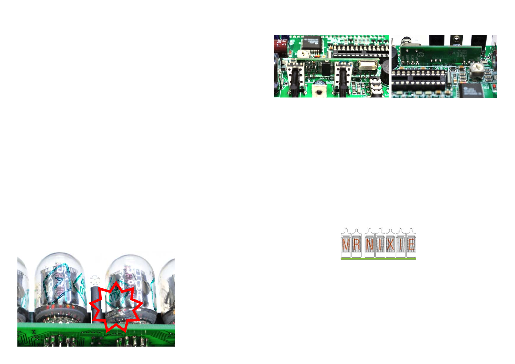
When using the ASK module from the Wireless GPS Set 3, simply fit the module onto the mainboard and
solder the 8 pins. Pay attention for correct orientation (see pictures).
The clock has a build in antenna. However, due to the RF shielding of the aluminium profiles the reception
range is very limited. If the reception is too poor you can connect the supplied external antenna to the
TIME DATA connector. Don’t forget to set option #12 to value 4 (for GPS reception) option #13 to the
baud rate and option #14...16 to correct the time offset according to your location; this offset is based
on standard time (not day saving).
The green LED below the module will show the received data as well as the DATA LED on rear.
Please note that it is not possible to connect any extra external receiver to the TIME DATA
connector when an ASK module is fitted, only the supplied antenna can be fitted.
Please check again, if the solder jumper A-B-C (direct below the module) is soldered in position A-B
when using the internal ASK module. For setting up the „Wireless GPS Connection“ system proceed as
stated in the appropriate owners manual
When connecting the wired extrenal MicroGPS / NWTS receiver from PVelectronics set the
jumpers A-B-C to position B-C set option #12 to value 4 and check for correct baud rate settings.
When connecting the wired external GPS BR-355 receiver from GlobalSat set the jumpers
A-B-C to position A-B and check for 4800 baud rate settings (option #13 to value 0).
When connecting the wired external DCF receiver from Mr.Nixie you’ll need to set the
jumpers A-B-C to position A-B and set option #12 to value 1 and omit option #13
Crack
The following task must only be done when assembling a
Laura Nixie clock
Pick up the 4 x M3 x 8 self tapping screws and the 4 x 3 mm plastic
spacers and threat them to the drilling holes at the edges of the main
board. The spacers are a self fixing type.
A note for handling the
IN-2 Nixie tubes
Please be very carefully by
handling the IN-2 tubes.
The glass bottom is very
fragile and will brake when
applying hard force,
specially when inserting
into the socket or by
aligning the tubes. You
need not to press down
the tubes fully into their
sockets. Only the half is
much enough.
Anbieterkennzeichung • Vendor
Jürgen Grau • Ortsstraße 13 • 07429 Rohrbach • Germany • Fon: 036730 / 3155-90 • Fax: 036730 / 3155-89
Subject change without notice – Issue 3.3 – Version from 08.06.2017
Date
05.08.2012
08.08.2012
26.08.2012
27.09.2012
11.11.2012
17.02.2014
17.04.2015
27.12.2016
08.06.2017
E-Mail: [email protected] • www.Nixiekits.eu
Description
Initial Release
Error correction / added replacing diodes procedure
Error correction / parts value of resistor-arrays changed
Changed the range of the voltage measuring values
Added assembly of Lena Nixie clock
New issue for the new main board version Rev.11-2013
Error correction and additions in GPS receiver settings
Corrected value of the measured voltages on PIC socket
Adding settings for DCF / NWTS receivers
Page 3

Assembly Manual Miniature USB powered Nixie Clocks • Mainboard Rev.11-2013
Assembling the Lars IN-17 tube board and enclosure
Please crack carefully both PCB’s.
Assemble now the male headers (1 x 32-pol. and 3 x 2-pol.) and the 4 resistors on the tube board.
Flip the board and assemble the four LED’s. Slight over the LED’s wires 2 x 8 mm spacers each
(8 in total). Pay attention that the anode of the LED is the longer wire and it is marked on the silk
screen with an „A“. Solder at the beginning only one pad, than adjust the LED’s exact upright and
solder the remaining pad.
Pick up now an IN-17 tube. Please
note that one wire is missing on
each tube as marking for the correct
mounting direction. This missing wire
has also no Star Milling pad on the
PCB.
See the red markings on the picture.
Thread all tube wires carefully through the
Star Milling cut out.
Bend all wires into the slots of the Star Milling
pads. Keep care not to cross any wires.
Cut the wires. Now solder only one pad.
Align the tube carefully for correct adjustment
by re-heating the soldered pad.
If you are satisfied, solder the remaining pads.
Please take care not to make any short circuits
between the pads.
Continue this task for the remaining 5 tubes.
Pick up now the LED board and solder the 3 x 2-pol. female headers and the 6 resistor arrays.
The „polarity“ of the arrays is negligable.
Page 4

Assembly Manual Miniature USB powered Nixie Clocks • Mainboard Rev.11-2013
Assemble now the 6 RGB LEDs
but do not solder them yet.
The longest (thrid) wire is the
Anode, marked with an „A“ on the
silk screen
Attach now the front to the tubes. From rear align the column LEDs that their lens will fit into the drill
Fit the LED board on the tube board.
Align now all LEDs is that way, that
their lens will touch the drill hole in
the tubes plastic socket.
Solder carefully all LEDs. Take
special care not to make any
short ciruits between the LED
pads as the spacing is very
small. Take as less solder tin
as possible.
holes of the front cover.
Pick up one enclosure aluminium profile and slide the main board into the lowest nut of the profile.
Attach following the second aluminium profile
After soldering cut all leads.
Stop here: Turn back to the
assembly of the main board for
a quick function check of the
tube board.
Pick up one rubber surround.
Please take care for the correct
side. Remove from the front cover
the protective film on the copper
coloured side and insert the front
cover carefully into the rubber
surround
wrong side
Finally fix - starting with the front - the covers with the supplied screws (you’ll need a Torx Tx10
screwdriver). Don’t twist the screws by force and keep care not to cam out with your screwdriver
as this will scratch the cover or even damage the tubes
Finished assembling. Congratulations and have a lot of fun with your new
Lars Nixie Clock
Page 5

Assembly Manual Miniature USB powered Nixie Clocks • Mainboard Rev.11-2013
Assembling the Laura IN-2 tube board and enclosure
Pick up the tube board and assemble first the 32-pol. male header. Solder first only one pad and
check for proper rectangular alignement of the header. When satisfied solder the remaining pads.
2.5 mm spacing
Now threat over every tube pin a supplied tube
socket pin.
Sometimes the tube pins needs to be bend a little
bit. Do this very carefully as the glass bottom is
very fragile.
Now assemble the four LED’s. Slight
over the LED’s wires 2 x 8 mm spacers
each (8 in total). Pay attention that the
anode of the LED is the longer wire and
it is marked on the silk screen with an
„A“. Solder at the beginning only one
pad, than adjust the LED’s exact upright
and solder the remaining pad.
Please note not to forget to give
around 2.5 mm extra spacing for
the LEDs as shown in the picture.
Please pull out carefully (!) all
tubes in that way that they are
only fitted around the half of their
socket pins lenght in the soldered
female PCB sockets.
Attach now the front cover to the
tubes, but do not remove the
protective films at this stage.
From rear align the column LEDs
that their lens will fit into the drill
holes of the front cover.
Remove both protective films from
the bottom cover and fix the board
on it with the 4 x M2.5 x 8 screws.
Insert following all six tubes with the tube socket
pins into their socket drill holes in the PCB.
Do not solder them yet. After inserting all tubes
align them carefully for equal spacing and tube’s
height. When you are satisfied solder now the tube
socket pins. Take care not to make any solder
bridges as the spacing between the pins is very
small. Do not trim the pins after soldering!
Stop here: Turn back to the assembly of the main board for a quick function check of
the tube board.
Remove both protective films from the first transparent distance holder. Remove the protective film
from the brass coloured side of the front cover and than from the rear side, which is self-adhesive.
Affix now the front cover onto the distance holder. Check for symmetrical allignment.
Do the same task with both rear frames (the engraved
rear cover do not have any protective film).
Fix the rear side now with the supplied four 3 x 14 black
Allan screws (you’ll need a Torx Tx10 screwdriver) onto
the aluminium side frames
Page 6
Assembly Manual Miniature USB powered Nixie Clocks • Mainboard Rev.11-2013
Assembling the Lena tube board and enclosure
Slide now the bottom cover
into the lowest notches of
the side frames.
Pick up the tube board and assemble first the 32-pol. male header. Solder first only one pad and
check for proper rectangular alignement of the header. When satisfied solder the remaining pads.
After removing both
protective films from the
transparent top cover slight it
into the most upper notches
of the side frames.
Fix the PCB / bottom frame
with the supplied M3 x 6
Allan head screw on the
rear side.
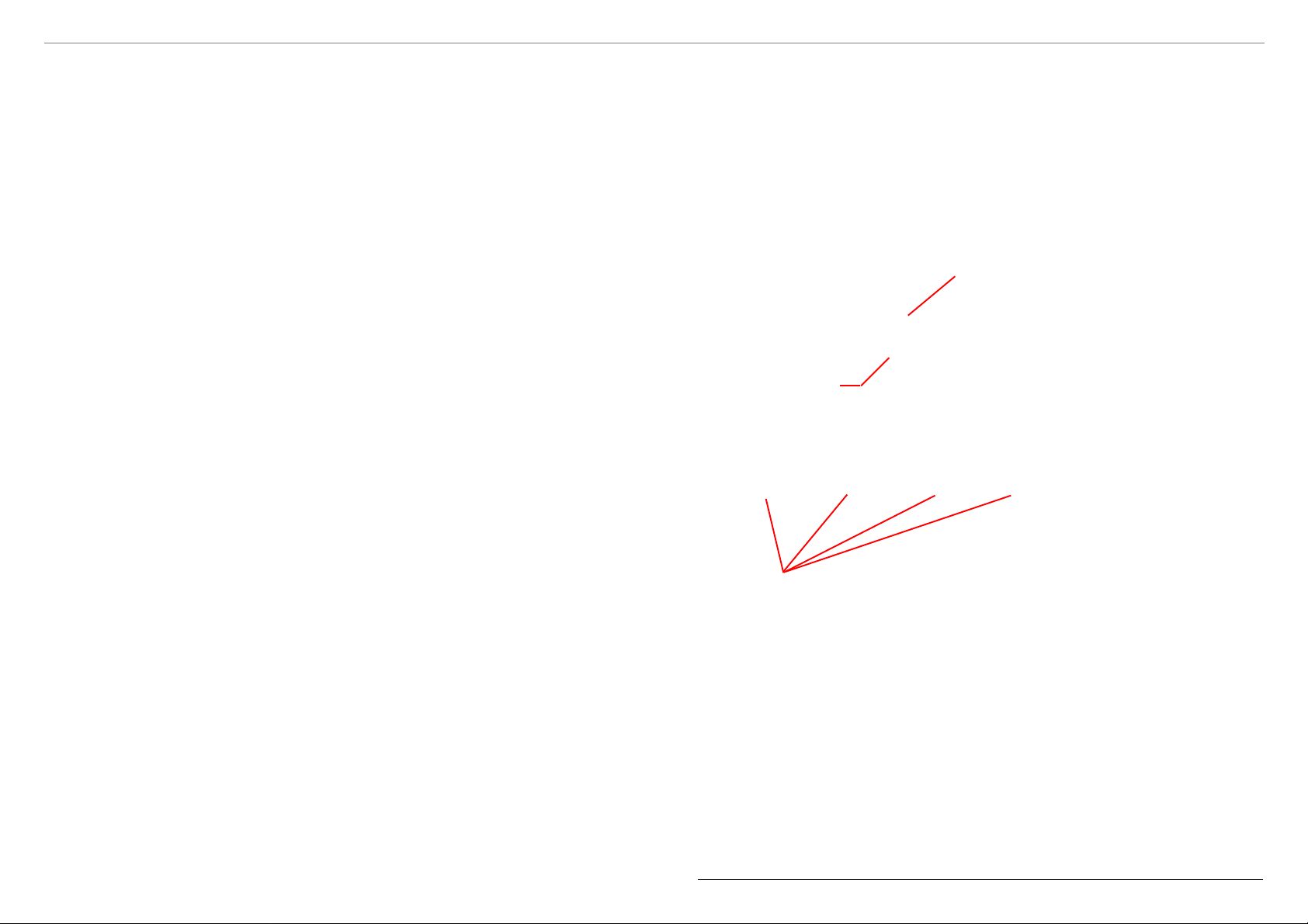
Anode pin
Do not fit a socket
on this pin #12
Anode pins
and tube’s height. When you are satisfied solder now the tube socket pins from the bottom side.
Do not trim the pins after soldering!
Now remove all tubes and solder the sockets also
from the top side. Be careful not to solder the
socket’s holes. Use as less solder tin as possible.
When finished attach the two 3 mm LEDs with two
8 mm plastic spacer each to their position. The longer
wire is the Anode of the LED and marked on the PCB
with an „A“; the shorter wire is the Cathode, marked
with a ring.
Now threat over every tube pin except
of pin # 12 (left hand from the Anode
pin) a supplied tube socket.
Sometimes the tube pins needs to be
bend a little bit. Do this very carefully as
the glass bottom is very fragile.
Insert following all four IN-12 tubes
with the tube socket pins into their
socket drill holes in the PCB. Take care
for correct orientation. Note the white
shrink tube inside the glas
bulb which marks the
Anode connection.
Do not solder
them yet. After
inserting all tubes
align them carefully
for equal spacing
Finally attach the front cover and fix it with the remaining 4 screws and add the 4 pcs. foam feed
onto the edges of the bottom cover.
Finished assembling. Congratulations and have a lot of fun with your new
Laura Nixie Clock
When finished solderin the LEDs re-attach
the IN-12 tubes into their sockets again.
Page 7

Assembly Manual Miniature USB powered Nixie Clocks • Mainboard Rev.11-2013
Pick up now both RGB LEDs
and bend them as shown in
the picture. The longest wire
is the Anode, marked on the
silkscreen with an „A“. Finally
attach the LEDs to the tube board and
solder carefully the connections. Be
aware that the pad spacing is very low,
so use as less tin as possible to
produce no short circuits between
these pins. Check also not to make a
short circuit to the added wire link.
Pick up now both IN-17 tubes and remove their
plastic spacers. Now cut the leads in a kind of
a „spiral staircase“ as shown in the picture.
This will help you to easy fit the tubes into their
drilling holes, which should be done following
this cutting.
Solder only one wire first and adjust the tube
for correct spacing and allignment as shown in
the pictures. Than solder and cut the remaining
wires.
Unfortunately on the first batch of the tubes
PCBs one track is missing which causes that
the digit „0“ will not shown on the 1st seconds
tube. So pick up a piece of wire and add the
missing connection from the 10th seconds to
the 1st seconds tube as shown on the picture.
Take care not to make any short circuits.
Wire link
Remove from the front cover the protective film from front- and rear side.
Note that the rear side is self-adhesive. Attach the front cover carefully at
the U aluminium frame and fix it with four of the supplied M3 x 14 black
screws.
Than slide the board from the rear into the enclosure.
Remove from the acrylic cover both protective
films and slide it into the most upper nut into
the U frame.
Remove from the rear cover the protective film on the self-
adhesive side and attach it at the U frame.
Fix the cover first with the M3 x 6 screw and following with the remaining
M3 x 14 black screws.
Finally attach on the bottom the supplied
transparent self-adhesive feeds.
Finished assembling. Congratulations
and have a lot of fun with your new
Lena Nixie Clock.
Stop here: Turn back to
the assembly of the
main board for a quick
function check of the
tube board.
Page 8
Part List Rev.11-2013
USB powered Nixie Clocks
Through hole components Main PCB Rev.11-13 for all clock versions
Qty Part description Value Position / Code
1 Duo-LED green / green LED11
1 Duo-LED red / yellow LED12
4 LED spacer 8 mm Tube Board
2 Dual push button switch S1, S2
1 Buzzer SND1
1 Super Capacitor 0.1F, 0.33F or 1F 5V5 C17
1 Electrolytic capacitor 2200uF 6V3 C4
1 Electrolytic capacitor 2u2 350V C16
1 Potentiometer 47k TR1
1 Crystal 32.756 kHz Q1
1 IC-Socket 28-pol. IC1
1 16F1938 Processor 16F1938 IC1
1 IC-Socket 28-pol. PLCC IC2
1 HV5812 HV-Driver 28-pol. PLCC IC2
1 Shielded Inductor 47uH L8
1 MosFet Transistor RFD3055L T14
1 Female Connector 90° 32-pol. 32-pol.
1 Male Connector 180° 32-pol. 32-pol.
1 Mounting Bracket M3 / 3.2
1 Sheet metal screw 2.9 x 9.5
1 Allan flat hat screw M3 x 6
1 Rosette 10.5 mm diameter Plastic black
1 Main Board SMT preassembled white
Electrical Parts for Laura Nixie Clock Tube Board
Ca. 70 Tube socket pins H1…H6
Mechanical Parts for Laura Nixie Clock
4 LED 1,8mm Amber clear Tube Board
4 LED spacer 8 mm Tube Board
4 Screw self tapping M2.5 x 8
8 Alan flat hat screw self tapping 3 x 14
4 Spacers 2.7 inner x 3 plastic
4 Foam feeds 12 x 12 mm
1 Front cover 1.6 mm brass col.
1 Rear cover 1.6 mm brass col.
1 Top cover 2 mm transparent
1 Bottom cover 3 mm black
2 Aluminium side frames Black anodized
1 IN-2 Tube Board Board preassembled
Electrical Parts for Lars Nixie Clock Tube/LED Board
4 LED 1,8mm Amber clear Tube Board
4 LED spacer 8 mm Tube Board
6 Resistor-Array SIL6-3 560R RN1…RN6 on LED board
6 LED 5mm RGB comm. Anode LED1…LED6 on LED board
3 Female Connector 180° 2-pol. for LED board
3 Male Connector 180° 2-pol. for tube board
4 Resistors 0204 330R R7,R8,R15,R16
Mechanical Parts for Lars Nixie Clock
8 Alan flat hat screw self tapping 3 x 14 / 3 x 10
2 Aluminium enclosure frames Black anodized AKG D 105 30 80 SA
2 Rubber enclosure surrounds blue
1 Front cover 1.6 mm copper col.
1 Rear cover 1.6 mm copper col.
1 IN-17 Tube/LED Board Duo-Board with V-cut
Page 9
Part List Rev.11-2013
USB powered Nixie Clocks
Electrical Parts for Lena Nixie Clock Tube Board
44 Harwin tube socket pins H1…H6
Mechanical Parts for Lena Nixie Clock
8 Alan flat hat screw self tapping 3 x 14 / 3 x 10
2 LED 3mm Amber diffused LED7,LED8
2 LED 5mm RGB comm. Anode LED5,LED6
4+1 Transparent plastic feeds 7 mm diameter
1 Front cover 1.6 mm copper col.
1 Rear cover 1.6 mm copper col.
1 Top cover 2 mm transparent
1 Aluminium U frame Black anodized GB 83 83 SA
1 White Lena Tube Board Board preassembled
Electrical and Mechanical Parts for Leon Nixie Clock Tube Board
Ca. 70 Tube socket pins H1…H6
8 Alan flat hat screw self tapping M3 x 14
4 Alan flat hat screw self tapping M3 x 20
4 Roads Red pl astic
6 RGB-LEDs 5mm diffus LED1…LED6
2 Neons H7,H8
2 Resistors 510k R1,R2
6 Resistor Arrays 1k RN1…RN6
2 Aluminium side profiles
1 Rubber grommet
1 5/8” to 3/8” adapter
1 Nut for adapter
4 “Ears” Red plastic
4 Aluminium reinforcement frames
1 Leon Tube Board
1 Front cover 1,6 mm silvery
1 Rear cover 1,6 mm silvery engraved
1 Top cover 1,6 mm silvery
1 Bottom cover 1,6 mm silvery with drill hole for adapter
2 Reinforcement frames 3 mm acrylic transparent with drill hole
Page 10
5
C27
C27
10u
10u
C8
10uC810u
63V 63V
D4
R29
R29
680k
680k
SS16LD4SS16L
R28
R28
680k
680k
X1X1
X2X2
VCC
D8
SS16LD8SS16L
IC1
IC1
1
MCLR
2
HV SENSE
13
HV PWM
18
DCF/GPS
21
SET
22
ADJ
23
ALARM
24
DST
11
XTAL1/TCXO
PIC16F1938_IN-2
PIC16F1938_IN-2
12
XTAL2
17
SOUNDER
C25
C25
10u
10u
SND1
SND1
R38
R38
Sounder
Sounder
12k
12k
5
R37
R37
n.c.
n.c.
DCF
C3
10uC310u
S2S2
L1L1
C4
2200uC42200u
6V3
L2L2
C6
10uC610u
L8
47uHL847uH
BU2BU2
1
2
3
4
5
D D
T14
T14
RFD3055L
RFD3055L
R35
R35
12k
12k
C C
B B
HV ENABLE
R36
R36
12k
12k
C21
C21
33p
33p
C22
C22
33p
33p
Q1
32kQ132k
C23
C23
33p
33p
S1S1
A A
Title
Title
Title
USB powered Nixie Clock
USB powered Nixie Clock
USB powered Nixie Clock
Size Document Number Rev
Size Document Number Rev
Size Document Number Rev
A4
A4
A4
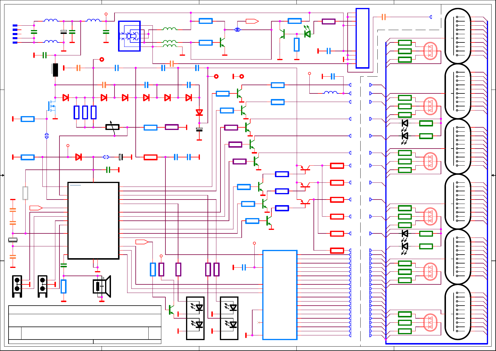
Main Board with IN-2 Laura Tube Board / Main board Rev.11-2013
Main Board with IN-2 Laura Tube Board / Main board Rev.11-2013
Main Board with IN-2 Laura Tube Board / Main board Rev.11-2013
Date: Sheet
Date: Sheet
Date: Sheet
VCC
L6L6
C26
C26
10u
10u
TP1TP1
C13
C13
10u
10u
D1
SS16LD1SS16L
R30
R30
680k
680k
HV ADJUST
-+
-+
BACKUP
ENABLE
X3X3
X4X4
C19
C19
10u
10u
20
LED AM
LED PM
VDD
LED DST
LED ALARM
LED DCF/GPS
LED R
LED G
LED B
DTA
CLK
STR
VSS
VSS
8
19
C91uC9
1u
TR122k
TR122k
0.1/1F
0.1/1F
A1
A2
A3
11Saturday, February 15, 2014
11Saturday, February 15, 2014
11Saturday, February 15, 2014
BU1
BU1
DCF/GPS
DCF/GPS
D2
SS16LD2SS16L
C17
C17
9
10
14
15
16
25
26
27
28
6
7
3
4
5
of
of
of
SS16LD5SS16L
DCF
R39
R39
12k
12k
C141uC14
1u
D5
R31
R31
12k
12k
R33
R33
2k7
2k7
4
11/2013
11/2013
11/2013
4
VCC
L3L3
L4L4
L5L5
C101uC10
1u
D3
SS16LD3SS16L
R63
R63
470R
470R
R60
R60
470R
470R
T151DT15
1D
C7
33pC733p
C181uC18
1u
C151uC15
1u
D6
SS16LD6SS16L
D7
SS16LD7SS16L
C201uC20
1u
R40
R40
470R
470R
LED11LED11
R23
R23
12k
12k
R24
R24
12k
12k
C111uC11
1u
R41
R41
470R
470R
C16
C16
2u2
2u2
R43
R43
12k
12k
POLARITY
TP2TP2
R44
R44
12k
12k
R45
R45
470R
470R
R42
R42
470R
470R
LED12LED12
AA
T21DT2
1D
R46
R46
470R
470R
R47
R47
470R
470R
BB CC
R48
R48
12k
12k
T31DT3
1D
R49
R49
12k
12k
C241uC24
1u
3
DCF
TP3TP3
T41DT4
1D
R50
R50
12k
12k
3
T51DT5
1D
VCC
T61DT6
1D
T71DT7
1D
1
28
27
15
13
2
14
T11DT1
1D
R61
R61
12k
12k
R62
R62
12k
12k
R51
R51
680k
680k
T81DT8
R52
R52
1D
680k
680k
R53
R53
T91DT9
1D
680k
680k
T101DT10
1D
IC2
IC2
HV5812
HV5812
VHV
VDD
DATA
CLK
STROBE16HV11
HV20
HV19
HV18
HV17
HV16
HV15
HV14
HV13
HV12
HV10
BLANK
DOUT
GND
R25
R25
12k
12k
HV9
HV8
HV7
HV6
HV5
HV4
HV3
HV2
HV1
3
4
5
6
7
8
9
10
11
12
17
18
19
20
21
22
23
24
25
26
R26
R26
12k
12k
T112DT11
2D
T122DT12
2D
T132DT13
2D
LED13LED13
VCC
R27
R27
470R
470R
C51uC5
1u
L7L7
C121uC12
1u
R54
R54
2k7
2k7
R55
R55
2k7
2k7
R56
R56
2k7
2k7
R57
R57
2k7
2k7
R58
R58
2k7
2k7
R59
R59
2k7
2k7
2
GND
SHT
DAT
5V
OPTIONAL1
OPTIONAL1
5V
GND
GND
ANT
C1
33pC133p
IN-2 Laura Tube Board
ASK-RXB2
ASK-RXB2
Track 17,4 cm
A1
LR
R1R1
LG
R2R2
LB
R3R3
VC
LED1LED1
R
G
B
22 x 560R 0603
AM
NAMNAM
MAMMAM
VC
MVCMVC
NVCNVC
NPMNPM
MPMMPM
MLRMLR
NLRNLR
MLGMLG
NLGNLG
NLBNLB
MLBMLB
MA1MA1
NA1NA1
MA2MA2
NA2NA2
MA3MA3
NA3NA3
MA4MA4
NA4NA4
MA5MA5
NA5NA5
MA6MA6
NA6NA6
N10N10
M10M10
N1N1
M1M1
N2N2
M2M2
M3M3
N3N3
N4N4
M4M4
M5M5
N5N5
M6M6
N6N6
N17N17
M17M17
N18N18
M18M18
M19M19
N19N19
N20N20
M20M20
N11N11
M11M11
M12M12
N12N12
N13N13
M13M13
M14M14
N14N14
N15N15
M15M15
M16M16
N16N16
N7N7
M7M7
N8N8
M8M8
M9M9
N9N9
2
A2
PM
LR
LG
LB
A1
LR
LG
LB
VC
AM
AM
A3
LR
LG
LB
VC
R4R4
R5R5
R6R6
R9R9
R10R10
R11R11
LED7LED7
LED8LED8
LED2LED2
R
G
B
R7R7
R8R8
LED3LED3
R
G
B
A2
A3
A4
LR
R12R12
A4
LG
R13R13
LB
R14R14
VC
A5
PM
PM KK8
A6
K10
A5
K1
K2
LR
LG
LB
VC
A6
LR
LG
LB
VC
R17R17
R18R18
R19R19
R20R20
R21R21
R22R22
K3
K4
K5
K6
KK7
KK8
KK9
KK10
KK1
KK2
KK3
KK4
KK5
KK6
K7
K8
K9
LED9LED9
LED10LED10
LED4LED4
R
G
B
R15R15
R16R16
LED5LED5
R
G
B
LED6LED6
R
G
B
1
H1H1
Z1Z1
A
A
A
A
A
A
A
A
A
A
A
A
1
K10
0
K9
9
K8
8
K7
7
K6
6
K5
5
K4
4
K3
3
K2
2
K1
1
H2H2
K10
0
K9
9
K8
8
K7
7
K6
6
K5
5
K4
4
K3
3
K2
2
K1
1
H3H3
K10
0
K9
9
K8
8
K7
7
K6
6
K5
5
K4
4
K3
3
K2
2
K1
1
H4H4
KK10
0
KK9
9
KK8
8
KK7
7
KK6
6
KK5
5
KK4
4
KK3
3
KK2
2
KK1
1
H5H5
KK10
0
KK9
9
8
KK7
7
KK6
6
KK5
5
KK4
4
KK3
3
KK2
2
KK1
1
H6H6
KK10
0
KK9
9
KK8
8
KK7
7
KK6
6
KK5
5
KK4
4
KK3
3
KK2
2
KK1
1
Page 11
5
4
3
2
1
RN1...6 = 3 x 560R/680R Array
R7,R8,R15,R16 = 330R
MC
D D
VC
A1
MR
MG
MB
MC
X7X7
RN1ARN1A
RN1BRN1B
RN1CRN1C
X8X8
LED1LED1
R
G
B
A
A
MR
LR
AM
NAMNAM
VC
PM
LR
LG
LB
A1
A2
A2
MR
MG
MB
VC
AM
AM
A3
MR
MG
MB
MC
MG
NVCNVC
NPMNPM
NLRNLR
NLGNLG
C C
NLBNLB
NA1NA1
NA2NA2
LG
A3
NA3NA3
NA4NA4
NA5NA5
NA6NA6
N10N10
N1N1
N2N2
N3N3
B B
N4N4
N5N5
N6N6
N17N17
N18N18
N19N19
N20N20
N11N11
N12N12
N13N13
N14N14
N15N15
N16N16
N7N7
N8N8
N9N9
A4
A5
A6
K10
K1
K2
K3
K4
K5
K6
KK7
KK8
KK9
KK10
KK1
KK2
KK3
KK4
KK5
KK6
K7
K8
K9
A4
MR
MG
MB
VC
PM
PM
A5
MR
MG
MB
MC
MB
LB
A6
MR
MG
MB
MC
X1X1
RN2ARN2A
RN2BRN2B
RN2CRN2C
RN3ARN3A
RN3BRN3B
RN3CRN3C
X3X3
RN4ARN4A
RN4BRN4B
RN4CRN4C
RN5ARN5A
RN5BRN5B
RN5CRN5C
X5X5
RN6ARN6A
RN6BRN6B
RN6CRN6C
X2X2
LED7LED7
LED8LED8
X4X4
LED9LED9
LED10LED10
X6X6
LED2LED2
R
G
B
A
A
R7R7
R8R8
LED3LED3
R
G
B
LED4LED4
R
G
B
A
A
A
A
R15R15
R16R16
LED5LED5
R
G
B
LED6LED6
R
G
B
A
A
A
A
H1H1
K10
0
K9
9
K8
8
K7
7
K6
6
K5
5
K4
4
K3
3
K2
2
K1
1
H2H2
K10
0
K9
9
K8
8
K7
7
K6
6
K5
5
K4
4
K3
3
K2
2
K1
1
H3H3
K10
0
K9
9
K8
8
K7
7
K6
6
K5
5
K4
4
K3
3
K2
2
K1
1
H4H4
KK10
0
KK9
9
KK8
8
KK7
7
KK6
6
KK5
5
KK4
4
KK3
3
KK2
2
KK1
1
H5H5
KK10
0
KK9
9
KK8
8
KK7
7
KK6
6
KK5
5
KK4
4
KK3
3
KK2
2
KK1
1
H6H6
KK10
0
KK9
9
KK8
8
KK7
7
KK6
6
KK5
5
KK4
4
KK3
3
KK2
2
KK1
1
A A
Title
Title
Title
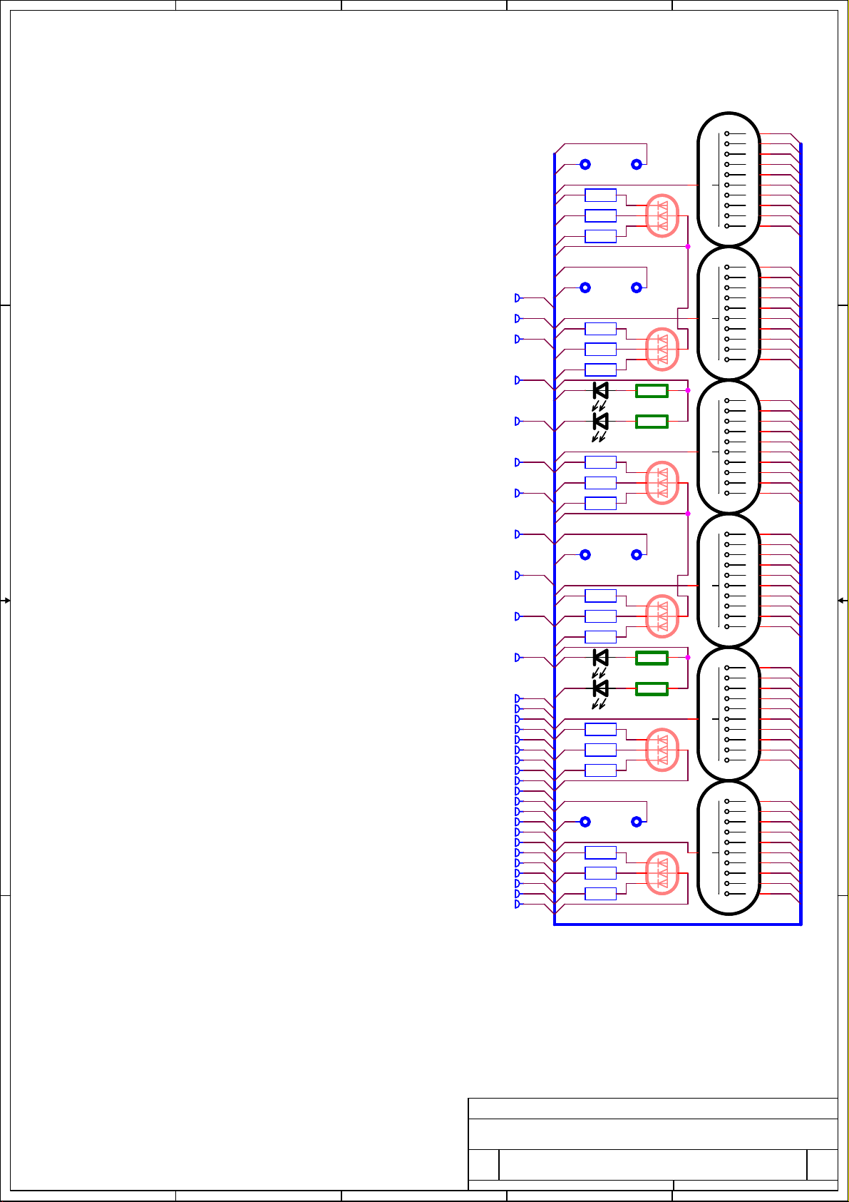
Lars Tube/LED Board
Lars Tube/LED Board
Lars Tube/LED Board
Size Document Number Rev
Size Document Number Rev
Size Document Number Rev
for USB Nixie Clock Main Board 0
for USB Nixie Clock Main Board 0
for USB Nixie Clock Main Board 0
Date: Sheet
Date: Sheet
5
4
3
Date: Sheet
2
of
11Sunday, November 11, 2012
of
11Sunday, November 11, 2012
of
11Sunday, November 11, 2012
1
Page 12
5
4
3
2
1
VC
LR
D D
NAMNAM
NVCNVC
NPMNPM
NLRNLR
NLGNLG
NLBNLB
LG
LB
VC K7
PM
A1
LR K3
LG K1
LR
LB
LG
LB
R171kR17
1k
R181kR18
1k
A1
A2
A3
A4
A5
A6
K0
K1
K2
K3
K4
K5
K6
KS7
KS8
KS9
KS0
KS1
AM
A2
PM
LR
LG
LB
A3
LR
LG
LB
A4
LR
NA1NA1
NA2NA2
NA3NA3
NA4NA4
NA5NA5
NA6NA6
R151kR15
1k
R161kR16
1k
N10N10
C C
N1N1
N2N2
N3N3
N4N4
N5N5
N6N6
N17N17
N18N18
N19N19
N20N20
B B
N11N11
LG
KS2
KS3
KS4
LB
A5
N12N12
N13N13
N14N14
LR
KS5
N15N15
LG
LB
N16N16
N7N7
N8N8
A A
N9N9
KS6
K7
K8
K9
A6
R71
R71
470R
470R
R41
R41
470R
470R
R51
R51
470R
470R
R61
R61
470R
470R
R72
R72
470R
470R
R42
R42
470R
470R
R52
R52
470R
470R
R62
R62
470R
470R
R7
470RR7470R
R8
470RR8470R
R73
R73
470R
470R
R43
R43
470R
470R
R53
R53
470R
470R
R63
R63
470R
470R
R74
R74
470R
470R
R44
R44
470R
470R
R54
R54
470R
470R
R64
R64
470R
470R
R451kR45
1k
R551kR55
1k
R651kR65
1k
R461kR46
1k
R561kR56
1k
R661kR66
1k
LED1
LED1
RGB
RGB
R
G
B
LED2
LED2
RGB
RGB
R
G
B
LED7AMLED7
AM
LED8PMLED8
PM
LED3
LED3
RGB
RGB
R
G
B
LED4
LED4
RGB
RGB
R
G
B
LED5
LED5
RGB
RGB
R
G
B
LED6
LED6
RGB
RGB
R
G
B
H1
IN-12H1IN-12
A
1
A
A
H2
IN-12H2IN-12
1
A
H3
A
IN-12H3IN-12
1
A
H4
A
IN-12H4IN-12
1
A
H5
IN-17H5IN-17
A
A
H6
IN-17H6IN-17
A
A
DP
DP
DP
DP
0
9
8
7
6
5
4
3
2
1
0
9
8
7
6
5
4
3
2
1
0
9
8
7
6
5
4
3
2
1
0
9
8
7
6
5
4
3
2
1
0
9
8
7
6
5
4
3
2
1
0
9
8
7
6
5
4
3
2
1
K0
2
K9AM
3
K8
4
5
K6
6
K5
7
K4
8
9
K2
10
11
12
K0
2
K9
3
K8
4
K7
5
K6
6
K5
7
K4
8
K3
9
K2
10
K1
11
12
K0
2
K9
3
K8
4
K7
5
K6
6
K5
7
K4
8
K3
9
K2
10
K1
11
12
KS0
2
KS9
3
KS8
4
KS7
5
KS6
6
KS5
7
KS4
8
KS3
9
KS2
10
KS1
11
12
KS0
KS9
KS8
KS7
KS6
KS5
KS4
KS3
KS2
KS1
KS0
KS9
KS8
KS7
KS6
KS5
KS4
KS3
KS2
KS1
Title
Title
Title
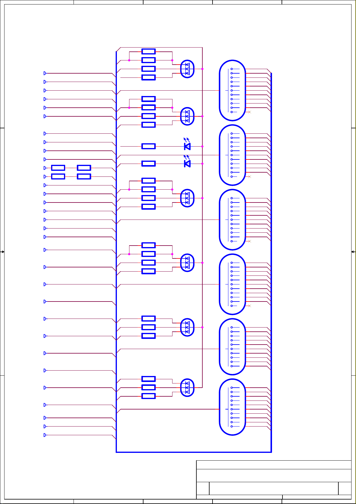
Lena Nixie Clock Tube Board
Lena Nixie Clock Tube Board
Lena Nixie Clock Tube Board
Size Document Number Rev
Size Document Number Rev
Size Document Number Rev
for USB Nixie Clock Main Board 0
for USB Nixie Clock Main Board 0
for USB Nixie Clock Main Board 0
Date: Sheet
Date: Sheet
5
4
3
Date: Sheet
2
of
11Sunday, November 11, 2012
of
11Sunday, November 11, 2012
of
11Sunday, November 11, 2012
1
Page 13
Assembly Manual Miniature USB powered Nixie Clocks • Mainboard Rev.11-2013
 Loading...