


User manual
NivuLog Easy
User Manual for the GPRS Data Logger NivuLog
Easy
(Original Instruction Manual - German)
Rev. 05 valid from:
l Firmware version: 02v003
l Modem version: 02v003 and 3v002
l Hardware version: 2.1
NIVUS GmbH
Im Taele 2
75031 Eppingen, Germany
Phone: +49 (0)7262 9191-0
Fax: +49 (0)7262 9191-999
E-mail: info@nivus.com
Internet: www.nivus.de
NivuLog Easy - Rev. 05 as of 02.07.2012 1 of 73


Chapter 1 Table of contents
Chapter 1 Table of contents
User Manual for the GPRS Data Logger NivuLog Easy 1
Chapter 1 Table of contents 3
Chapter 2 Declaration of conformity 7
Chapter 3 Specifications 9
Chapter 4 General specifications 11
4.1 Translation 11
4.2 Copyright 11
4.3 General descriptive names 11
4.4 Safety instructions 11
4.4.1 Use of the hazard warnings 12
4.4.2 Safety and preventative measures for handling GSM/GPRS modems 12
4.4.2.1 Safety and precautionarymeasures for the GSM/GPRS modem installation 12
4.4.2.2 Safety measuresfor installing the antenna 13
4.5 Overview 13
4.6 Intended use 14
4.7 General product information 14
4.8 Device labelling 15
4.9 Installation of replacement and wear parts 16
4.10 Storage of the product 16
4.11 Obligation of the operator 16
Chapter 5 Functional Principle 17
5.1 ALOHA transmission mode 17
Chapter 6 Storage, delivery and transport 19
6.1 Inspection of incoming deliveries 19
6.2 Scope of delivery 19
6.3 Storage 19
6.4 Transportation 20
6.5 Return 20
Chapter 7 Installation 21
7.1 Dimensions 21
7.2 Installing the NivuLog Easy 21
NivuLog Easy - Rev. 05 as of 02.07.2012 3 of 73

7.2.1 Wall mounting 22
7.3 Safety instructions for the cabling 23
7.4 Electrical installation 24
7.4.1 Connecting the sensors, actuators and supply 24
7.4.2 Connecting the GSM antenna 27
7.4.3 Technical details regarding the universal inputs 28
7.4.3.1 0/4 to 20mA mode 28
7.4.3.2 0 to 2V mode 28
7.4.3.3 0 to 10V mode 28
7.4.3.4 Standard digital modes(PWM, frequency, digital, day counter, impulse counter) 28
7.4.3.5 Low power digital mode (LP digital) 28
7.4.4 Technical details regarding the outputs 29
7.4.4.1 Output 1: Switchable sensor supply (Vout) 29
7.4.4.2 Output 2: Isolated switch contract (NO, CC) 29
7.4.4.3 Direct accu or battery voltage output (Vbatt) 29
7.4.5 Technical details regarding energy management 30
Chapter 8 Initial Start-Up 31
8.1 User information 31
8.2 General principles 31
8.3 Placing the system into operation 31
8.4 Testing the communication with the device 32
Chapter 9 User interfaces 35
9.1 User interface on the NivuLog Easy 35
9.1.1 Operating elements 35
9.1.1.1 Status LED 35
9.1.1.2 Buttons 36
9.1.1.3 Solenoid switch 37
9.2 User interface on the Device to Web-Server 37
9.2.1 Site configuration 37
9.2.1.1 Site 37
9.2.1.2 Comments 37
9.2.1.3 Measurement channels 37
9.2.1.3.1Basis 37
4 of 73 NivuLog Easy - Rev. 05 as of 02.07.2012

Chapter 1 Table of contents
9.2.1.3.2Config 40
9.2.1.3.3Alarms 52
9.2.1.3.4Trigger 52
9.2.1.4 Calculated channels 53
9.2.1.4.1Basis 53
9.2.1.4.2Calculation 54
9.2.1.4.3Alarm 54
9.2.1.5 Output channels 54
9.2.1.5.1Basis 54
9.2.1.5.2Config 56
9.2.1.6 Internal channels 56
9.2.1.6.1Basis 56
9.2.1.6.2Alarms 56
9.2.1.6.3Trigger 57
9.2.1.7 Alarm settings 57
9.2.1.8 Basic settings 58
9.2.1.9 FTP export settings 59
9.2.2 Device configuration 59
9.2.2.1 Comments 60
9.2.2.2 Measurement instrument 60
9.2.2.3 Device-specific settings 62
9.2.2.4 GPRS 62
Chapter 10 Maintenance 63
10.1 General maintenance 63
10.2 Replacing the accu or battery pack 63
10.2.1 Charging the accu pack 65
10.3 Accu or battery pack 66
Chapter 11 Removal/disposal 67
Chapter 12 Troubleshooting and repair 69
12.1 General problems 69
12.2 Evaluating the device log 70
12.2.1 Evaluating the device log on the Device to Web server 70
12.2.2 Evaluating the device log using DeviceConfig 70
NivuLog Easy - Rev. 05 as of 02.07.2012 5 of 73

Chapter 13 Spare parts and accessories 71
13.1 Internal expansions 71
13.2 Assemblysets 71
13.3 Antennas 71
13.4 Accu and battery packs 71
13.5 Sensors 72
13.6 Other accessories 72
Chapter 14 Branch offices 73
6 of 73 NivuLog Easy - Rev. 05 as of 02.07.2012

DE / EN / FR
EU Konformitätserklärung
EU Declaration of Conformity
Déclaration de conformité UE
Für das folgend bezeichnete Erzeugnis:
For the following product:
Le produit désigné ci-dessous:
NIVUS GmbH
Im Täle 2
75031 Eppingen
Telefon: +49 07262 9191-0
Telefax: +49 07262 9191-999
E-Mail: info@nivus.com
Internet: www.nivus.de
Bezeichnung:
Description:
Désignation:
GPRS Datenlogger
GPRS Data logger
Enregistreur de données GPRS
Typ / Type: NivuLog 4, NivuLog PCM, NivuLog Easy
erklären wir in alleiniger Verantwortung, dass die auf dem Unionsmarkt ab dem Zeitpunkt der Unterzeichnung
bereitgestellten Geräte die folgenden einschlägigen Harmonisierungsvorschriften der Union erfüllen:
we declare under our sole responsibility that the equipment made available on the Union market as of the date of signature of
this document meets the standards of the following applicable Union harmonisation legislation:
nous déclarons, sous notre seule responsabilité, à la date de la présente signature, la conformité du produit pour le marché de
l’Union, aux directives d'harmonisation de la législation au sein de l’Union:
• 2014/30/EU • 2014/35/EU • 2015/53/EU • 2011/65/EU
Bei der Bewertung wurden folgende einschlägige harmonisierte Normen zugrunde gelegt bzw. wird die Konformität
erklärt in Bezug die nachfolgend genannten anderen technischen Spezifikationen:
The evaluation assessed the following applicable harmonised standards or the conformity is declared in relation to other
technical specifications listed below:
L’évaluation est effectuée à partir des normes harmonisées applicable ou la conformité est déclarée en relation aux autres
spécifications techniques désignées ci-dessous:
• EN 61326-1:2013 • EN 61010-1:2010 • EN 301489-1 V1.9.2:2011
• EN 301489-7 V1.3.1:2005 • EN 301511 V9.0.2:2003
Diese Erklärung wird verantwortlich für den Hersteller:
This declaration is submitted on behalf of the manufacturer:
Le fabricant assume la responsabilité de cette déclaration:
NIVUS GmbH
Im Taele 2
75031 Eppingen
Allemagne
abgegeben durch / represented by / faite par:
Marcus Fischer (Geschäftsführer / Managing Director / Directeur général)
Eppingen, den 20.04.2016
Gez. Marcus Fischer


Chapter 3 Specifications
Chapter 3 Specifications
Voltage supply Battery pack BP434R: 2 x Li-SOCl2-Cells fullyfabricated with 26Ah
Accu pack AP413D+: 2 x Li-ion - Accu cell fully fabricated with 13,6Ah
Charging voltage
7...30VDC (typically 170mA@12V)
(only when using an
accu pack)
Housing Material: Luran
Weight: 400g (without accu or battery)
Protection class: IP66
Dimensions (WHD): 86 x 165 x 64mm (without antenna)
Operating
-20...+60°C, 15...90%rH non-condensing
temperature
Storage
-30...+85°C
temperature
Display LED for indicating the operating mode and error code. (Only visible when the housing
cover is open)
Operation Button (with the housing cover open) or solenoidswitch (with the housingcover
closed) to initiate the ALOHA transmission mode
Antenna connection FME
Universalinputs 4 x analogue or digital
Modes:
l 0 to 20mA: Resolution 6µA, max. 22,5mA, load 100Ω
l 4 to 20mA: Resolution 6µA, max. 22,5mA, load 100Ω
l 0 to 2V: Resolution 610µV, max. 2,5V, load 220k1
l 0 to 10V: Resolution 8,3mV, max. 32V, load 8k9
l PWM: 1...99%, max. 100Hz, min. impulse length 1ms, load 8k9
l Frequency: 1...1000Hz, 8k9
l Digital: max. 32V, low <1,36V, high >2,73V, load 8k9
l Digital LP: max. V
l Day counter: min. impulse length 20ms, load 8k9
l Intervalcounter: min. impulse length 20ms, load 8k9
, low <100mV, high >200mV, load 220k1
Batt
Additional information is providedin "Technical detailsregarding the universal inputs"
on page 28.
External
1 x Cable temperature sensor 3m(todo) (Optional equipment)
temperature sensor
NivuLog Easy - Rev. 05 as of 02.07.2012 9 of 73

Outputs 1 x switchable sensor supply
l Standard: 15...19,5VDC, max. 66mA
l Order option: 24...31VDC, max. 41mA
1 x isolated switch contact
l I
l U
l R
l f
max
max
on
max
: 130mA
: 32V
: 35Ω
: 500Hz
Additional information is providedin "Technical detailsregarding the outputs " on page
29.
Data memory Internal flash memoryfor up to 25.580 measurement cycles
Data type f32 (32 Bit floating point)
Data transmission By means of GSM/GPRS quad-band modem to the relevant Device to Web server
SIM The NivuLog Easy is equipped with an integrated SIM chip.
Monthly data volume <4MB for two minute measurement cycle and 120 minute transmission cycle
10 of 73 NivuLog Easy - Rev. 05 as of 02.07.2012

Chapter 4 General specifications
Chapter 4 General specifications
The information in this manual has been compiled with great care and to the best of our knowledge. The manufacturer, however, assumes no liability for any incorrect specifications that may possibly occur in this manual
The manufacturer is not responsible for direct, indirect, accidental or consequential damages which arise
from errors or omissions in this manual even if advised of the possibility of such damages. In the process of
continuous product development, the manufacturer reserves the right to make improvements to this manual
and the products describedin it at any time and without prior notification or obligation.
Note: The specifications of this manual are valid as of the versions listed on the title page. Revised specifications of this manual, as well as software and driver updates are available in the service area of the Device
to Web-Server.
4.1 Translation
For deliveries in the countries of the European Economic Area, the manual is to be translated into the respective language of the country of the user. Should discrepancies occur in the translated text, the original manual
(German) is to be referred to for clarification or the manufacturer is to be contacted.
4.2 Copyright
The copying, distribution and utilisation of this document as well as the communication of its contents to
others without expressed authorisation is prohibited. Contraventions are liable to compensation. All rights
reserved.
4.3 General descriptive names
The use of general descriptive names, trade names, trademarksand the like in this manualdoes not entitle
the reader to assume they may be used freely by everyone. They are often protected registered trademarks
even if not marked as such.
4.4 Safety instructions
For the connection, commissioning and operation of the NivuLog Easy , the following information and higher
legal regulations of the country (e.g. ÖVE), such as valid EX regulations as well as the applicable safety and
accident prevention regulations for the respective application case must be observed.
Please read this manual completely before unpacking, setting up or operating this device. Observe all hazard,
danger and warning information. Non-observance can lead to serious injuries to the operator and/or damage
to the device.
Ensure that the safety equipment of this measurement device is not impaired. Install and use the measuring
system only in the manner and methoddescribed in this manual.
NivuLog Easy - Rev. 05 as of 02.07.2012 11 of 73

Important note: The manufacturer's products that are designed for use outside have extensive protection against penetrating moisture and dirt. If these products are connected by cables with connectors rather than permanently installed cables to the power supply or sensors, the susceptibility of
the connector and socket to moisture and dirt penetration are significantly higher. The operator is
responsible for protecting the connector and socket against penetrating moisture and dirt in a suitable
way and complying with local safety regulations.
4.4.1 Use of the hazard warnings
DANGER:
Indicates a potential or threatening hazardous situation that will result in death or serious
injuries if not avoided.
WARNING:
Indicates a potential or threatening hazardous situation that can result in death or serious
injuries if not avoided.
CAUTION:
Indicates a potential hazardous situation that can result in minor or moderate injury.
Note: Indicates a situation that does not result in any injury to persons.
Important note: Indicates a situation that can result in damages to this instrument if it is not avoided.
Information that must be particularly emphasised.
Note: Information that supplements the specifications in the main text.
4.4.2 Safety and preventative measures for handling GSM/GPRS modems
Observe the following safety and preventative measures during all phases of installation, operation, maintenance or repair of a GSM/GPRS modem. The manufacturer shallnot be held liable if the customer disregards these preventative measures.
CAUTION:
The GSM/GPRS modem connection may not be used in hazardous environments.
No guarantee of any kind, whether implicit or explicit, is given by the manufacturer and its suppliers
for the use with high risk activities.
In addition to the following safety considerations, all directives of the country in which the device is installed
must be compliedwith.
Important note: No liability shall be assumed at any time and under no condition for the connection
via a GSM/GPRS modem for whose use radio signals and networks are utilized, The GSM/GPRS
modem must be switched on and be operated in an area where sufficient signal strength is present.
4.4.2.1 Safety and precautionary measures for the GSM/GPRS modem installation
l This device may onlybe installed by a trained technician who applies the recognised installation prac-
ticesfor a radio frequency transmitter including the of external antennas.
l The device may not be operated in hospitalsand/or near medical equipment such as heart pacemakers
or hearing aids.
l The device may not be operated in highly flammable areas such as petrol filling stations, fuel storage
sites, chemicalfactories and explosion sites.
l Do not operate the device in the vicinity of flammable gases, vapours or dusts.
12 of 73 NivuLog Easy - Rev. 05 as of 02.07.2012

Chapter 4 General specifications
l Do not subject the device to strong vibrations or impacts.
l The GSM/GPRS modem can cause interference if it is located near television equipment, radios or
computers.
l Do not open the GSM/GPRS modem. Any modification to the equipment is prohibited and shalllead to
lossof the operating licence.
l The use of GSM services (SMS messages/data communication/GPRS etc.) may lead to additional
costs. The user alone is responsiblefor any damages and costs resulting through this.
l Do not install the device in any other manner than the one described in the operating instructions. An
improper use will invalidate the warranty.
4.4.2.2 Safety measures for installing the antenna
l Onlyuse antennas that are recommended or supplied by the manufacturer.
l The antenna must be installed at a distanceof at least 20 cm from individuals.
l The antenna must not be extended outside protected buildings and must be protected against lightning
strikes.
l The voltage supplymust be switched off before replacing the antenna.
4.5 Overview
Overview NivuLog Easy
NivuLog Easy - Rev. 05 as of 02.07.2012 13 of 73

1 Antenna connection 4 Pressure compensation
2 Housing cover 5 M20x1.5 cable screw connection (cable diameter
of 5 to 10mm)
3 M12x1.5 cable screw connection (cable diameter
of 3.5 to 7 mm)
4.6 Intended use
The portable measurement instrument is used to collect analogue and digital signals. The device can operate
without mains power. The measured and recorded data is stored in a non-volatile memory medium. This
stored data is sent to a central server for further processing via the mobile network. The device is equipped
with an integrated SIM chip for this purpose. The maximum permissible limit values set out in chapter "Specifications" on page 9 must be observed. The manufacturer shall not be liable for any operational casesthat
deviate from these limit values and have not been approved by the manufacturer in writing .
Note: This device is exclusively intended to be used for the purposes as described above. Any other
use or use beyond what is specified or a modification of the device shall be deemed to be not for the
intended purpose and is not permitted without the express written consent of the manufacturer. The
manufacturer shall not be held liable for any damages that may result from such unauthorised use or
modification. The operator alone bears the associated risk.
Note: The manufacturer is not liable for data loss of any kind if the device is damaged and data is not
able to be stored correctly.
Note: The integrated SIM chip provides a mobile communications connection to a variety of international service providers. In order to be able to utilise all functions of the device, you must ensure that
the device is located in the service area of one of these service providers. You can find a list of all supported countries and associated service providers under www.nivus.com. A Managed Service contract with NIVUS GmbH is required for use of the mobile data transmission (see www.nivus.com).
This includes the provisioning of the mobile communications connection via the network of the service
provider included in the above-mentioned list.
4.7 General product information
The device is a compact, portable instrument for recording and transmitting analogue and digital signals.
There are 4 universal inputs available, which can be operated in various analogue and digital modes. Additionally, an one wire bus is available for connecting an external temperature sensor. 2 output channelsare
also available. One of the two directlyswitches the sensor supply. The other is a galvanised isolated switch
contact. Both output channels can be configured independently so that they can each be switched by the
device prior to a measurement (to supply the sensor) or they can be switched wirelessly from a central location. All of the input measurement data is temporarily saved to an internal data memory along with the output
statuses and are then wirelessly transmitted to a centrallocation at freely selected intervals. The device is
also configured via this connection. The device is equipped with an integrated SIM chip. If the optional
SIM/USB option is available, the device can also be configured via the USB interface.
14 of 73 NivuLog Easy - Rev. 05 as of 02.07.2012

Chapter 4 General specifications
4.8 Device labelling
The specifications in this manual applyexclusively to the device type NivuLog Easy . The type plate is located
on the right side of the device and includes the following specifications:
l Name and addressof manufacturer
l CE marking
l Protection class
l Environmental conditions during operation
l Electrical parameters for the installed switchable sensor supply
l Hardware revision
l Order number
l Serial number
The correct specification of the Order number and serialnumber is important for all queriesand spare part
orders. Only then can we process requestspromptly and properly.
NivuLog Easy type plate
Note: This symbol indicates that the NivuLog Easy is equipped with an integrated SIM chip.
Note: These operating instructions are part of the device and must be available for the user at all
times. The safety instructions included therein must be observed.
DANGER:
It is strictly prohibited to disable the safety equipment or modify its mode of operation.
NivuLog Easy - Rev. 05 as of 02.07.2012 15 of 73

4.9 Installation of replacement and wear parts
Please be advised that replacement and accessory parts that have not been supplied by the manufacturer
have also not been inspected or approved by it. Installing or using such products and similar can constructivelymodify the specified propertiesof the device in a negative way. The manufacturer shall not be liable
for any damages that arise from the use of non-original parts and non-original accessory parts.
4.10 Storage of the product
Ensure that all of the relevant data has been transmitted to the Device to Web server before storing the NivuLog Easy . If necessary initiate the ALOHA transmission mode using the magnetic contact (see "ALOHA
transmission mode" on page 17) and then check again that all relevant data has been transmitted. If you are
using an external charging voltage to charge the accu pack of the NivuLog Easy , disconnect this from the
device before removing the accuor battery pack. The remaining cables and antenna can then be removed.
Store the NivuLog Easy and accuor battery pack in the compartments provided in the original packaging.
The configuration and most recently determined data are retained. However, the systemclock will not continue to work without an energy supply. This means that following recommissioning, the time must be synchronised to ensure that measurement and log data timestamps are correct. This occurs automatically either
when the first connection is established with the Device to Web server or when the NivuLog Easy is connectedto the PC. For this purpose, the optional SIM/USB option and DeviceConfig configuration program
are required.
4.11 Obligation of the operator
WARNING:
In the EEA (European Economic Area), the national implementation of the framework direc-
tive (89/391/EEC) as well as the associated specific directives and from these in particular,
the directive (89/655/EEC) about the minimum safety and health requirements for use of
work equipment by workers at work, each in their respective version are to be complied
with.
The operator must obtainthe local operating licence and the associated documents.
In addition, the operator must comply with the local legal requirements for
l the safety of the personnel(accident prevention measures)
l the safety of the equipment (protective equipment and maintenance)
l the product disposal (waste disposal law)
l the material disposal (waste disposal law)
l the cleaning (cleaning agents and disposal)
l and the environmental protection amendments.
Before commissioning, the operator must ensure that the installation and commissioning – providedthese
were performed by the operator himself – are in compliance with the local regulations.
16 of 73 NivuLog Easy - Rev. 05 as of 02.07.2012

Chapter 5 Functional Principle
Chapter 5 Functional Principle
5.1 ALOHA transmission mode
ALOHA transmission mode is a special connection mode whereby the NivuLog Easy creates a connection to
the Device to Web server for a period of time configured using the "Basic settings" configuration section (see
"Aloha/wake-up duration" in chapter "Basicsettings" on page 58).
There are two optionsfor initiating the ALOHA transmission mode:
l Directly on the device by meansof the solenoid switch (see "Solenoid switch" on page 37) or button
(see "Buttons" on page 36).
l Via the Device to Web sever if the "Interval & Wakeup" connection type has been selected (see "Basic
settings" on page 58).
A speech bubble in the measurement device list (see "Device to Web Server Manual " - upon request) with
the title "Aloha" indicates that a device is in ALOHA transmission mode.
Clicking on the speech bubble with the "Aloha" title opens the ALOHA data window (see "Device to Web
Server Manual " - upon request). It includes the internal"voltage", "GSM level"and "battery" measurement
values, as well as the measurement values of the 4 universal inputs. The measurement values for the last
thirty minutesare always shown in the ALOHA data window, this can mean that data from a previous ALOHA
transmission is included. The ALOHA data is generated every three seconds independentlyof the normal
measurement valuesthat are generated and is thus not saved with the standard measurement data.
If a measurement dataset is recorded during ALOHA transmission mode, it is immediately transmittedto the
Device to Web server and saved in the standard measurement data.
NivuLog Easy - Rev. 05 as of 02.07.2012 17 of 73


Chapter 6 Storage, delivery and transport
Chapter 6 Storage, delivery and transport
6.1 Inspection of incoming deliveries
Please check the shipment immediately after receiving for completeness and intactness. Immediately report
any discovered transport damagesto the delivering carrier. Also notify the manufacturer in writing about this
without delay. Report any incompleteness in the delivery to the responsible representative or directly to the
company headquarters of the manufacturer within 2 weeks (see "Branch offices " on page 73).
Note: Any claims received thereafter will not be acknowledged!
6.2 Scope of delivery
Note: The accu or battery pack required for operation, (see "Accu and battery packs" on page 71) is
not part of the standard scope of delivery and must be ordered separately.
The standard scope of delivery of the NivuLog Easy (206.210) includes:
l NivuLog Easy
l Tool Pen (NLM0TOOLPEN)
l 10-pole connector plug
l Magnet for device activation (NLM5MAGNET)
l Quick guide
Additional equipment suchas internal extensions, assemblysets, antennas, accu or battery pack, sensors,
power supply, charger, etc., depending on the order. Please check this against the delivery slip.
6.3 Storage
The following storage conditions must be observed:
NivuLog Easy Storage temperature -30...+85°C
Humidity 15...90%rH
BP434R Operating temperature -20...+50°C
Storage temperature 0...+35°C
AP413D+ Operating temperature -50...+60°C
Charging temperature -20...+60°C
Storage temperature 0... +30°C
Note: The table above only includes the storage conditions for the two energy sources used most frequently for
the NivuLog Easy . Please consult the appropriate factsheet for information about the storage conditions of
other accu or battery packs.
Important note: Remove the accu or battery pack from the NivuLog Easy prior to storage.
Store the measurement technology so that it is protected against corrosive or organic solvent vapours, radioactive emissions and strong electromagnetic radiation.
NivuLog Easy - Rev. 05 as of 02.07.2012 19 of 73

6.4 Transportation
The NivuLog Easy is designed for rough industrial applications. Nevertheless, it should not be subjected to
heavyshocks, bumps, impacts or vibrations. The original packaging must always be used for transport.
6.5 Return
Every return must be accompanied by a fully field-out return form. This return form is available in the service
area of the Device to Web-Server. An RMA number is mandatory for any returns and can be obtained from
the Support & Service Centre (see "Branch offices " on page 73). The return shipment of the NivuLog Easy
must occur in the original packaging and with freight and insurance paid to NIVUS GmbH (see "Branch
offices " on page 73). Insufficiently cleared return shipments will otherwise not be accepted!
20 of 73 NivuLog Easy - Rev. 05 as of 02.07.2012

Chapter 7 Installation
Important note: The work described in this section of these instructions must only be performed by
qualified personnel to prevent any damage to the device.
7.1 Dimensions
Chapter 7 Installation
Dimensions: Width and height Dimensions: Depth
7.2 Installing the NivuLog Easy
Important note:
l Ensure the installation is completed properly.
l Comply with the existing legal and/or operational directives.
l Improper handling can cause injuries and/or damage to the devices.
NivuLog Easy - Rev. 05 as of 02.07.2012 21 of 73

The installation site must be selected according to specific criteria. The following conditions must be avoided
in any case:
l Direct sunlight
l Objects that radiate intense heat (maximum ambient temperature: -20...+60°C)
l Objects with a strong electromagnetic field (frequency converter or similar)
l Corrosive chemicals or gases
l Mechanicalimpacts
l Direct installation on foot or road ways
l Vibrations
l Radioactive emissions
Note: Leave sufficient space at the upper end to mount the antenna. The space required depends on the
antenna used. Approx. 15 cm of space must be left beneath the device for the cable connections. Further
information about the installation dimensions can be found in the relevant sub-chapter.
7.2.1 Wall mounting
For wall mounting the optional "Universal bracket for housing NivuLog Easy 86x126(NLM0HALEASY)"
equipment is required.
Step 1 of the wall mounting Step 2 of the wall mounting
1 NivuLog Easy 3 Assembly loop (included in the delivery scope of
NLM0HALEASY)
2 Delta PT M3.5x8 Torx 15 (included in the delivery
scope of NLM0HALEASY)
4 Raised head tapping screw 3.5x32 (included in
the delivery scope of NLM0HALEASY)
1. First attach the assembly loop (3) using the screws (2) included in the "Universalbracket for housing
NivuLog Easy 86x126 (NLM0HALEASY)" equipment set to the NivuLog Easy (see "Step 1 of the wall
mounting" on page 22).
22 of 73 NivuLog Easy - Rev. 05 as of 02.07.2012

2. Drilling the holes for mounting:
If you want to use the tapping screws (4) included in the equipment set to secure the assembly loop
(3) to the wall, drill four 6-mm holes in the wall using the drill template as a guide in accordance with
the dimensions in the diagram "Step 2 of the wall mounting" on page 22.
If you want to use your own fastening screws you can use the drill guide provided in the equipment
set to determine the position of the holes. The diameters are then determined by the screws that are
being used and any wall plugs that may be required.
3. Securing the NivuLog Easy to the wall:
If you want to use the tapping screws (4) included in the equipment set, first of all insert the supplied
wall plugs into each of the four drill holes before screwing the NivuLog Easy with the attached
assembly loop (3) to the wall (see "Step 2 of the wall mounting" on page 22).
If you are using your own screws, you must also insert the wall plugs into the holes before mounting
the NivuLog Easy with the attached assembly loop (3) to the wall (see "Step 2 of the wall mounting"
on page 22).
7.3 Safety instructions for the cabling
Chapter 7 Installation
Important note: To avoid any damage, always switch off the voltage supply to the device when
performing electrical connections.
When connections are made to the NivuLog Easy , the following warningsand information must be observed,
in addition to the warnings and information found in the individual chapters on the installation. Further safety
information is included in "Safety instructions" on page 11.
If present, disconnect the external charging voltage from the device and removethe accu or battery pack
before completing any wiring work.
Removing the accu or battery pack
NivuLog Easy - Rev. 05 as of 02.07.2012 23 of 73

1 Housing cover 3 Accu or battery pack
2 Supplyconnector
7.4 Electrical installation
Important note: Only qualified personnel should undertake the installation described in this chapter
of the operating instructions to avoid any damage to the device.
7.4.1 Connecting the sensors, actuators and supply
Important note:
l All cabling work must be performed in the de-energised state.
l Ensure a proper installation.
l Comply with the existing legal and/or operational directives.
l Improper handling can cause injuries and/or damage to the devices.
l Run all data and power cables so that they do not pose a stumbling risk and ensure that the
cables do not have any sharp bends.
l The NivuLog Easy must not be operated in the field with the lid open.
l The NivuLog Easy cannot be operated without an internal power supply (accu or battery pack).
l Ensure the polarity of the connector is correct when replacing the accu or battery pack.
l An external charging (V
is used.
l To ensure the housing is properly sealed, each of the two cable screw connections must only
hold a single cable.
) voltage must not be connected to the NivuLog Easy if a battery pack
in
24 of 73 NivuLog Easy - Rev. 05 as of 02.07.2012

Chapter 7 Installation
Connection of the sensors and supply
1 Housing cover 7 Pressure compensation
2 Supplyconnector 8 M16x1.5 cable screw connection (cable diameter
of 4.5 to 10 mm)
3 Accu or battery pack 9 Main terminal blockX12
4 Antenna connection 10 Mounting for the accu or battery pack
5 connector X4 for the external temperature sensor 11 Status LED
6 M12x1.5 cable screw connection (cable diameter
12 Button
of 3.5 to 7 mm)
NivuLog Easy - Rev. 05 as of 02.07.2012 25 of 73

Allocation of the main terminal block X12
1 V
in
External charging voltage
2 GND Earthing
3 V
out
Output 1: Switchable sensor
supply
4 V
batt
Direct accu or battery voltage
output
5 Input 1 Universalinput 1
6 Input 2 Universalinput 2
7 Input 3 Universalinput 3
8 Input 4 Universalinput 4
9 NO Output 2: Isolated switch contact
10 CC
1. Remove the four screws that secure the housing cover. Then open the NivuLog Easy .
Important note: In the event of adverse weather conditions including rain or in a location
where water can penetrate from above, suitable measures must be implemented to protect the
device from penetrating moisture when the housing cover is open.
2. Connection of the external temperature sensor:
If the external temperature sensor was ordered at the same time as the NivuLog Easy , it should
alreadybe connected correctly.
If you ordered an external temperature sensor at a later date as an accessory, the following steps
must be completed:
Important note: Please note that not every type of external temperature sensor can be
installed by the customer (see "Sensors" on page 72).
1. Remove the main terminal block. Ensure that the external charging voltage is switched off if it is
alreadyconnected to the main terminal block.
2. Remove the accu or battery pack.
3. Thread the sensor and its cable internally through the M12 cable screw connection.
4. Connect the connector of the externaltemperature sensor to the connector X4 for the external
temperature sensor .
5. Tighten the M12 cable screw connection to secure the sensor cable.
6. Install the accu or battery pack before fitting the main terminal block.
3. Then connect your sensors and actuators with the universal inputs and outputs. If you are using an
accu packto supply the NivuLog Easy , connect the external charging voltage to Vinand the GND.
Ensure that no current is present!
Important note: Only a single cable must be threaded through the cable screw connections to
ensure the seal of the housing is not damaged.
4. Tighten the cable screw connections to secure the cables.
26 of 73 NivuLog Easy - Rev. 05 as of 02.07.2012

Chapter 7 Installation
5. Affix blind plugs to all of the cable screw connectionsthat are not required.
Important note: All unused cable screw connections on the NivuLog Easy must be sealed
watertightly using the blind plugs supplied. Otherwise the degree of protection for the entire
device is not guaranteed and the manufacturer's warranty is void.
6. Insert the accu or battery pack into the NivuLog Easy and secure it with the appropriate mounting.
7. Connect the antenna (see "Connecting the GSM antenna" on page 27). The antenna is not included in
the scope of delivery and must be ordered separately.
8. Connect the accu or battery pack to the supply connector. The status LED should then start to flicker
(see "Status LED" on page 35), indicating that a connection is being established.
The following step is not mandatory.
9. Check whether the connection to the Device to Web has functioned correctly (see "Testing the
communication with the device" on page 32).
10. Close the housing cover. The best option is to tighten all four of the screws crosswise so that the
housing cover is positioned evenly.
Important note: Ensure that the seals are clean and intact before closing the housing cover.
Remove any foreign bodies and/or dirt. The manufacturer will not be liable for any damage to
the device caused by leaky or faulty seals.
The following step is onlynecessary if you are using an external charging voltage for the accu pack:
11. Now switch on the external charging voltage.
7.4.2 Connecting the GSM antenna
Important note: To ensure the correct functionality, only use antennas that are supplied by the
manufacturer.
The standard antenna is directly attached to the antenna connector (see "Overview" on page 13) of the
NivuLog Easy . In the event of a low radio signal strength, you can use the Flat antenna Smart Disc FME-F ( upon request).
If the distance between the antenna position and the NivuLog Easy is too great, you can use a 5 m Extension
for ANT900 FME (NLM0ANTVER05).
1. Ensure that the NivuLog Easy is de-energised.
2. If you need an antenna extension, connect this to the antenna first.
3. Connect the antenna extension or antenna directly to the antenna connection of the NivuLogEasy (see
"Overview" on page 13)
Important note: Do not apply too much force when tightening the antenna. Do not use any
tools to tighten the antenna or antenna extension; only tighten it manually.
4. Switch the power supply of the NivuLog Easy back on.
The following step is not mandatory.
5. Check whether the connection to the Device to Web has functioned correctly (see "Testing the
communication with the device" on page 32).
NivuLog Easy - Rev. 05 as of 02.07.2012 27 of 73

7.4.3 Technical details regarding the universal inputs
7.4.3.1 0/4 to 20mA mode
Note: Above 22,5mA, the affected input becomes highly resistive (safety shutdown to prevent damage to the
universal input).
Resolution 6µA
I
max
22,5mA
Load 100Ω
7.4.3.2 0 to 2V mode
Resolution 610µV
U
max
2,5V
Load 220k1
7.4.3.3 0 to 10V mode
Resolution 8,3mV
U
max
32V
Load 8k9
7.4.3.4 Standard digital modes (PWM, frequency, digital, day counter, impulse counter)
General U
max
32V
Low <1,36V
High >2,73V
Load 8k9
PWM Measurement
1...99%
range
f
max
Minimum pulse
100Hz
1ms
length
Frequency Measurement
1...1000Hz
range
Day and pulse
counter
Minimum pulse
length
20ms
7.4.3.5 Low power digital mode (LP digital)
Important note: If a universal input is in "LP digital", a switch contact must onlybe supplied by V
batt
.
Attaching an external voltage will cause damage to the universal input. In comparison to "digital" mode, the
energy consumption during "LP digital" mode with a closed switch contact is thus reduced by a factor of 13.
28 of 73 NivuLog Easy - Rev. 05 as of 02.07.2012
Chapter 7 Installation
U
max
V
batt
Low <100mV
High >200mV
Load 220k1
7.4.4 Technical details regarding the outputs
7.4.4.1 Output 1: Switchable sensor supply (V
Note: The switchable sensor supply output is short-circuit-proof.
P
I
max
max
1W
66mA
@15V
41mA
@24V
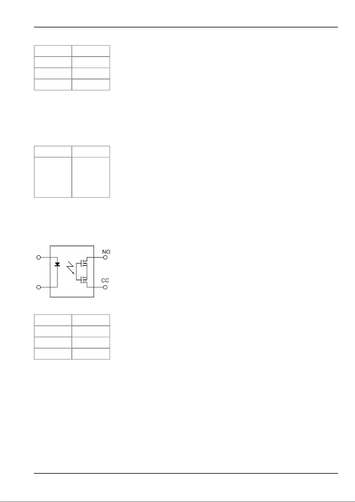
7.4.4.2 Output 2: Isolated switch contract (NO, CC)
out
)
Important note: The user must ensure that the current does not exceed 130mA via the isolated
switch contact.
Replacement circuit diagram for the isolated switch contact
I
max
U
max
R
on
f
max
7.4.4.3 Direct accu or battery voltage output (V
The accu or battery voltage is supplied directly to the voltage output V
130mA
32V
35Ω
500Hz
batt
)
protected by a PTC (I
batt
max
200mA).
The voltage available at this output is therefore directly dependent on the charging condition of the accu or
battery pack.
NivuLog Easy - Rev. 05 as of 02.07.2012 29 of 73

7.4.5 Technical details regarding energy management
The device will work until 3,1V, if the NivuLog Easy is operated without an external charging voltage (Vin). It
then switches to energy-saving mode in which only the charge controller is active. If an external charging
voltage (Vin) is supplied in this mode, the accu pack can be charged up again. Otherwise the NivuLog Easy
remainsin energy-saving mode until the accu pack is completely discharged.
When an externalcharging voltage (Vin) is used, the charge controller ensures that the accu pack is charged.
It is therefore necessary to select the type of accu used in the input screen of the device configuration (see
"Device-specific settings" on page 62). If a type of accu packis selected that is also assigned the title "solar",
the accu pack is constantly charged (recommended if a solar field is used to charge the accu pack). For all of
the other accu pack type settings, the accu pack is always charged to the maximum voltage, after which
charging is switched off and only reactivated when V
reached (used to optimise the service life of the accu pack).
All types of accu packs are only recharged if the ambient temperature does not have an impact on the
permissible range of the charging temperature. The permissible charging temperature is specified in the
factsheet for the relevant accu pack. Chapter "Accu and battery packs" on page 71 contains an overview of
the temperature ranges for several accu packs.
Note: Please be aware that some of the compatible accu packs cannot be charged at sub-zero temperatures.
Select an appropriate accu pack if you are expecting low temperatures during operation.
(see "Device-specific settings" on page 62) is
low
30 of 73 NivuLog Easy - Rev. 05 as of 02.07.2012

Chapter 8 Initial Start-Up
Chapter 8 Initial Start-Up
8.1 User information
Before you connect the NivuLog Easy and place it into operation, you must observe and complywith the following user information!
This manual contains all information that is required for using the device.
Is intended for technically qualified personnel who have the relevant knowledge and experience in the area of
measurement technology.
Read this manual carefully and completely in order to ensure the proper functioning of the NivuLog Easy .
Please contact our technical department if anything is unclear or if you encounter difficulties with regard to
installation, connection or configuration (see "Branch offices " on page 73).
If necessary, please also refer to the manuals of the accessory parts when commissioning the complete system. These manuals are includedin the scope of delivery of the accessory parts.
8.2 General principles
The entire measurement system may only be placed into operation after completion and inspection of the
installation. Study the manual thoroughlybefore placing into operation to prevent faulty or incorrect configuration.
Utilise the manual to familiariseyourself with the operation of the NivuLog Easy and the input screens of the
Device to Web-Server before you begin with the configuration.
8.3 Placing the system into operation
Note: It is recommended that the NivuLog Easy is first placed into operation in the office before permanently
mounting the device at the place of use. In doing so you should set a site for the later operation on the Device to
Web server (see "Device to Web Server Manual " - upon request) and determine a site configuration (see "Site
configuration" on page 37). Take the opportunity to get to know the functions of the device in a stable environment. You can also use suitable test signals to simulate the sensors to establish the optimum configuration
of the NivuLog Easy prior to its actual first use. This will reduce the time needed for on-site installation to a minimum.
1. Once you have completed all of the steps described in the section "Connecting the sensors, actuators
and supply" on page 24, the NivuLog Easy is ready for operation and should have already made its first
connection to the Device to Web server.
2. Create a site for the operation on the Device to Web server (see "Device to Web Server Manual " upon request).
3. Configure the created site accordingto your requirements (see "Site configuration" on page 37).
4. Linkthe NivuLog Easy with the createdsite (see "Site" on page 37).
5. Check whether the type of accu packset in the device configuration (see "Device-specific settings" on
page 62) matches the accu or battery pack that is being used.
NivuLog Easy - Rev. 05 as of 02.07.2012 31 of 73

Important note: The accu pack type must be configured correctly, otherwise the charging
curve will not be correct.
6. Activate the ALOHA transmissionmode (see "ALOHA transmission mode" on page 17) so that the site
configuration is transmitted to the NivuLog Easy .
8.4 Testing the communication with the device
1. Create a site for the operation on the Device to Web server (see "Device to Web Server Manual " upon request).
2. Configure the created site accordingto your requirements (see "Site configuration" on page 37).
3. Linkthe NivuLog Easy with the createdsite (see "Site" on page 37).
4. Initiate the ALOHA transmission mode (see "ALOHA transmission mode" on page 17) so that the configuration of the site is transmitted to the NivuLog Easy .
5. Wait until the list of measurement instrumentsindicates that the unit is in ALOHA transmission mode.
This is indicated by a speech bubble with the "Aloha" inscription.
The following steps are only required if you also want to test the measurement value acquisition and data
transmission.
6. Terminate the ALOHA transmission mode by clicking the crossin the speech bubble with the "Aloha"
inscription or wait for the duration of the ALOHA transmission mode. This period can be determined in
the basic settings (see "Basicsettings" on page 58) of the site configuration. The default setting is ten
minutes.
7. Then wire up the sensors (see "Connecting the sensors, actuators and supply"on page 24) and restart
the ALOHA transmission mode
Important note: All wiring work must be performed in the de-energised state.
8. Check the incoming data in ALOHA data window of the Device to Web server, which can be accessed
by clicking on the speech bubble with the "Aloha" inscription (see "Device to Web Server Manual " upon request). Particular attentionmust be paid to the internal "GSM level" and "battery" measurement
values.
32 of 73 NivuLog Easy - Rev. 05 as of 02.07.2012

Note: Additional explanation about evaluating the "GSM level":
"GSM level"
>-64dBm
-64 to -73dBm
-74 to -83dBm
-84 to -93dBm
-94 to -107dBm
<= -108dBm
Note: Additional explanation about evaluating the "battery":
"Battery"
> 3.81V
Chapter 8 Initial Start-Up
3,81V...3,70V
3,71V...3,63V
3,64V...3,59V
3,6V...3,19V
<= 3.2 V or invalid value
NivuLog Easy - Rev. 05 as of 02.07.2012 33 of 73


Chapter 9 User interfaces
Chapter 9 User interfaces
The configuration of the NivuLog Easy is carried out via the web interface on the Device to Web server (see
"User interface on the Device to Web-Server" on page 37), which your responsible sales partner will provide
to you.
9.1 User interface on the NivuLog Easy
9.1.1 Operating elements
A differentiation must be made between the operating elements of the NivuLog Easy that are only accessible
when the housing cover is open, and those that are also accessible when the housing is closed.
Operating elements that areaccessible when the housing
cover is open
1 Status LED 3 Solenoid switch
2 Buttons
9.1.1.1 Status LED
The status LED is used both to display the error/status codes and to indicate the current operating status. If
the ALOHA transmission mode was activated or the accu or battery pack was connected (PowerOn), the
statusLED shows the current operating status for 10 minutes. During these ten minutes, the error/status
codesare transmitted every three seconds.
Operating elements that areaccessible when the housing is
closed
NivuLog Easy - Rev. 05 as of 02.07.2012 35 of 73

Error/status codes
Blink code Description Solution/cause
0x Transport lock (GPRS OFF, measurement
OFF)
If the ALOHA transmission mode is initiatedby
the button or solenoid switch, the NivuLog
Easy switches back into "RUN" mode (GPRS
ON, measurement ON).
1x Last connection OK
2x Last transmission faulty Try again later
4x Standby (GPRS ON, measurement OFF) See "transport lock"
6x Offline (GPRS OFF, measurement ON) See "transport lock"
7x Network block/no matching provider l Improve position of the antenna
l Check whether the device is located in
the coverage area of a service provider
that is supported by the integrated SIM
chip (www.nivus.com)
l Lift the network block (see
"DeviceConfig Manual" - upon request)
8x No GSM network l Try again later
l Improve position of the antenna
10x No GPRS connection Improve position of the antenna
11x No myDatanet server accessible l Check whether port 51241 is enabled on
the Device to Web server
l Try again later
12x Faulty SIM chip Contact support
Operating statuses
Status
LED
Description
Flickering Establishing connection
Lightsup GPRS connection established or button/solenoid switch actuates
Off Normal measuring operation according to configuration until the next transmission
9.1.1.2 Buttons
The button can also be used to initiate the ALOHA transmission mode or to instruct the NivuLog Easy to
immediatelygive out the error/status code.
User action Device response Operation after releasing the button
Press briefly for
approx. one second
Status LED illuminates Error/status code is displayed (see "Status
LED" on page 35)
Press and hold for
five seconds
Status LED flashes three times and then
remainson
ALOHA transmission mode
36 of 73 NivuLog Easy - Rev. 05 as of 02.07.2012

Chapter 9 User interfaces
9.1.1.3 Solenoid switch
The solenoid switch initiates the same actions as the button. However, it can also be used with the housing
closed thanks to the Magnet for device activation (NLM5MAGNET) included in the scope of delivery.
9.2 User interface on the Device to Web-Server
9.2.1 Site configuration
Note: Several of the configuration fields in the following sub chapters may possibly be hidden depending on the
respective user level. In this case, please contact the Device to Web-Server administrator.
Click on the name of the site in the list of sitesto get to the input screen for configuring the site (see "Device to
Web Server Manual " - upon request).
9.2.1.1 Site
Customer
Specifies to which customer the site is assigned.
icon
Assign site to another customer
Name
Site designation (not relevant for the device or data assignment)
Instrument S/N
Serial number of the device that is linked to the site (device assignment!)
9.2.1.2 Comments
Comments
Empty comment field (is also displayed below the device type in the site list)
9.2.1.3 Measurement channels
9.2.1.3.1 Basis
Title 1-4
Freely selectable channel title for the universal inputs
Title 1Wire
Freely selectable channel title for the external temperature sensor
NivuLog Easy - Rev. 05 as of 02.07.2012 37 of 73

Mode
Basic settings for the measurement channel
Universal inputs
Off --- Measurement channel deactivated
(digital modes)
Digital Invert Inverts the input signal
Digital LP Invert Inverts the input signal
Cnt.Day Impulse Count value of an impulse in the measuring unit
Max Defines the upper scale end of the pointer instruments
Unit String, which is used as the measurement unit by all of the
server display elements
Decimal
places
Cnt.Intervl. Impulse Count value of an impulse in the measuring unit
Max Defines the upper scale end of the pointer instruments
Unit String, which is used as the measurement unit by all of the
Decimal
places
Freq Factor Factor by which the input signal is multiplied
Min Defines the lower scale end of the pointer instruments
Max Defines the upper scale end of the pointer instruments
Number of decimal places that are used by all of the server
display elements
server display elements
Number of decimal places that are used by all of the server
display elements
Unit String, which is used as the measurement unit by all of the
server display elements
Decimal
places
PWM 0% Start of measurement range in the measurement unit
100% End of measurement range in the measurement unit
Unit String, which is used as the measurement unit by all of the
Decimal
places
Number of decimal places that are used by all of the server
display elements
server display elements
Number of decimal places that are used by all of the server
display elements
38 of 73 NivuLog Easy - Rev. 05 as of 02.07.2012

Chapter 9 User interfaces
Universal inputs
(analogue
modes)
0-20mA 0% Start of measurement range in the measurement unit
100% End of measurement range in the measurement unit
Unit String, which is used as the measurement unit by all of the
server display elements
Decimal
places
Number of decimal places that are used by all of the server
display elements
4-20mA 0% Start of measurement range in the measurement unit
100% End of measurement range in the measurement unit
Unit String, which is used as the measurement unit by all of the
server display elements
Decimal
places
Number of decimal places that are used by all of the server
display elements
0-2V 0% Start of measurement range in the measurement unit
100% End of measurement range in the measurement unit
Unit String, which is used as the measurement unit by all of the
server display elements
Decimal
places
Number of decimal places that are used by all of the server
display elements
Ext. temperature
sensor
0-10V 0% Start of measurement range in the measurement unit
100% End of measurement range in the measurement unit
Unit String, which is used as the measurement unit by all of the
server display elements
Decimal
places
Number of decimal places that are used by all of the server
display elements
Off --- Measurement channel deactivated
On Min Defines the lower scale end of the pointer instruments
Max Defines the upper scale end of the pointer instruments
Unit Selection of the temperature unit that is used by all of the
server display elements
Decimal
places
Number of decimal places that are used by all of the server
display elements
NivuLog Easy - Rev. 05 as of 02.07.2012 39 of 73

9.2.1.3.2 Config
Universalinputs
(digital modes)
Off --- --Digital Filter time Minimum signal length for signal detection
Decay Temporalfunction in the measurement cycle
Up Minimum signal length for x seconds on rising
edge
Down Minimumsignal length for x seconds on
falling edge
Up & down Minimum signal length for x seconds on both
edges
Time Time x, for which the decay modes "up" "down", and "up &
down" are used
Digital LP Filter time Minimum signallength for signal detection
Decay Temporalfunction in the measurement cycle
Up Minimum signal length for x seconds on rising
edge
Down Minimumsignal length for x seconds on
falling edge
Up & down Minimum signal length for x seconds on both
edges
Time Time x, for which the decay modes "up" "down", and "up &
down" are used
40 of 73 NivuLog Easy - Rev. 05 as of 02.07.2012

Chapter 9 User interfaces
Universalinputs
(Counter modes)
Cnt.Day Filter time Minimum signal length for signal detection
Reset at Reset time of the day counter
Cnt.Intervl. Filter time Minimum signal length for signaldetection
Decay Temporalfunction in the measurement cycle
Off Decay deactivated
Min The minimum of the last x measurement
values is recorded.
Max The maximum of the last x measurement
values is recorded.
Avg The arithmetic mean of the last x
measurement valuesis recorded.
Med The median of the last x measurement
values is recorded.
Rms The root mean square of the last x
measurement valuesis recorded.
Time Time window for the decay. Up to max. 60 measurement
values can be used for the calculation (e.g. 1 channel: 60
measurement values; 4 channels: per 15 measurement
values). To calculate the number of considered
measurement valuessee "Example for explaining the
recording, measuring and burst cycles (in conjunction with
the decay)" on page 59.
NivuLog Easy - Rev. 05 as of 02.07.2012 41 of 73

Universalinputs
Freq
Filter time Minimum signal length for signal detection
(Frequencymode
1/2)
(1/2)
Decay Temporalfunction in the measurement cycle
Off Decay deactivated
Min The minimum of the last x measurement
values is recorded.
Max The maximum of the last x measurement
values is recorded.
Avg The arithmetic mean of the last x
measurement valuesis recorded.
Med The median of the last x measurement
values is recorded.
Rms The root mean square of the last x
measurement valuesis recorded.
Time Time window for the decay. Up to max. 60 measurement
values can be used for the calculation (e.g. 1 channel: 60
measurement values; 4 channels: per 15 measurement
values). To calculate the number of considered
measurement valuessee "Example for explaining the
recording, measuring and burst cycles (in conjunction with
the decay)" on page 59.
Hold Maintain the last valid measurement value for x
measurement cycles
Off Function deactivated
1-5 Number of measurement cyclesfor which
the measured value is maintained until the
error value is issued
On In the event of an error, the last valid
measurement value is maintained until a new
valid measurement value is present.
42 of 73 NivuLog Easy - Rev. 05 as of 02.07.2012

Chapter 9 User interfaces
Universalinputs
(Frequencymode
2/2)
Freq
(2/2)
Overflow Handling measurement range violations
Ignore The measured value is calculated beyond the
range limits.
Silent cutoff The measured value is cutoff at the range
limits.
Overflow l If the measurement value is below the
lower limit, the error value "UF"
(underflow) is issued.
l If the measurement value is above the
upper limit, the error value "OF"
(overflow) is issued.
NAMUR
borders
l If the measurement value is below the
lower limit, the error value "UF"
(underflow) is issued.
l If the measurement value is above the
upper limit, the error value "OF"
(overflow) is issued.
NivuLog Easy - Rev. 05 as of 02.07.2012 43 of 73

Universalinputs
PWM
Filter time Minimum signal length for signal detection
(PWM mode 1/2)
(1/2)
Decay Temporalfunction in the measurement cycle
Off Decay deactivated
Min The minimum of the last x measurement
values is recorded.
Max The maximum of the last x measurement
values is recorded.
Avg The arithmetic mean of the last x
measurement valuesis recorded.
Med The median of the last x measurement
values is recorded.
Rms The root mean square of the last x
measurement valuesis recorded.
Time Time window for the decay. Up to max. 60 measurement
values can be used for the calculation (e.g. 1 channel: 60
measurement values; 4 channels: per 15 measurement
values). To calculate the number of considered
measurement valuessee "Example for explaining the
recording, measuring and burst cycles (in conjunction with
the decay)" on page 59.
Hold Maintain the last valid measurement value for x
measurement cycles
Off Function deactivated
1-5 Number of measurement cyclesfor which
the measured value is maintained until the
error value is issued
On In the event of an error, the last valid
measurement value is maintained until a new
valid measurement value is present.
44 of 73 NivuLog Easy - Rev. 05 as of 02.07.2012

Chapter 9 User interfaces
Universalinputs
(PWM mode 2/2)
PWM
(2/2)
Overflow Handling
measurement
range
violations
Ignore
Silent cutoff The measured value is cutoff at the range
Overflow l If the measurement value is below the
NAMUR
borders
The measured value is calculated beyond the
range limits.
limits.
lower limit, the error value "UF"
(underflow) is issued.
l If the measurement value is above the
upper limit, the error value "OF"
(overflow) is issued.
l If the measurement value is below the
lower limit, the error value "UF"
(underflow) is issued.
l If the measurement value is above the
upper limit, the error value "OF"
(overflow) is issued.
NivuLog Easy - Rev. 05 as of 02.07.2012 45 of 73

Universalinputs
0-20mA
Filter time Temporal averaging for signal smoothing
(0-20mA mode 1/2)
(1/2)
Decay Temporalfunction in the measurement cycle
Off Decay deactivated
Min The minimum of the last x measurement
values is recorded.
Max The maximum of the last x measurement
values is recorded.
Avg The arithmetic mean of the last x
measurement valuesis recorded.
Med The median of the last x measurement
values is recorded.
Rms The root mean square of the last x
measurement valuesis recorded.
Time Time window for the decay. Up to max. 60 measurement
values can be used for the calculation (e.g. 1 channel: 60
measurement values; 4 channels: per 15 measurement
values). To calculate the number of considered
measurement valuessee "Example for explaining the
recording, measuring and burst cycles (in conjunction with
the decay)" on page 59.
Hold Maintain the last valid measurement value for x
measurement cycles
Off Function deactivated
1-5 Number of measurement cyclesfor which
the measured value is maintained until the
error value is issued
On In the event of an error, the last valid
measurement value is maintained until a new
valid measurement value is present.
46 of 73 NivuLog Easy - Rev. 05 as of 02.07.2012

Chapter 9 User interfaces
Universalinputs
(0-20mA mode 2/2)
0-20mA
(2/2)
Overflow Handling
measurement
range
violations
Ignore
Silent cutoff The measured value is cutoff at the range
Overflow l If the measured value is above
NAMUR
borders
The measured value is calculated beyond the
range limits.
limits.
20.1mA, the error value "SC" (short
cut) is issued.
l If the measuredvalue is above
20.1mA, the error value "OF"
(overflow) is issued.
l If the measuredvalue is above 21mA,
the error value "SC" (short cut) is
issued.
NivuLog Easy - Rev. 05 as of 02.07.2012 47 of 73

Universalinputs
4-20mA
Filter time Temporal averaging for signal smoothing
(4-20mA mode 1/2)
(1/2)
Decay Temporalfunction in the measurement cycle
Off Decay deactivated
Min The minimum of the last x measurement
values is recorded.
Max The maximum of the last x measurement
values is recorded.
Avg The arithmetic mean of the last x
measurement valuesis recorded.
Med The median of the last x measurement
values is recorded.
Rms The root mean square of the last x
measurement valuesis recorded.
Time Time window for the decay. Up to max. 60 measurement
values can be used for the calculation (e.g. 1 channel: 60
measurement values; 4 channels: per 15 measurement
values). To calculate the number of considered
measurement valuessee "Example for explaining the
recording, measuring and burst cycles (in conjunction with
the decay)" on page 59.
Hold Maintain the last valid measurement value for x
measurement cycles
Off Function deactivated
1-5 Number of measurement cyclesfor which
the measured value is maintained until the
error value is issued
On In the event of an error, the last valid
measurement value is maintained until a new
valid measurement value is present.
48 of 73 NivuLog Easy - Rev. 05 as of 02.07.2012

Chapter 9 User interfaces
Universalinputs
(4-20mA mode 2/2)
4-20mA
(2/2)
Overflow Handling
measurement
range
violations
Ignore
Silent cutoff The measured value is cutoff at the range
Overflow l If the measured value is below 3.9mA,
NAMUR
borders
The measured value is calculated beyond the
range limits.
limits.
the error value "OL" (open loop) is
issued.
l If the measuredvalue is above
20.1mA, the error value "SC" (short
cut) is issued.
l If the measuredvalue is below 3.6mA,
the error value "OL" (open loop) is
issued.
l If the measuredvalue is below 3.9mA,
the error value "UF" (under flow) is
issued.
l If the measuredvalue is above
20.1mA, the error value "OF"
(overflow) is issued.
l If the measuredvalue is above 21mA,
the error value "SC" (short cut) is
issued.
NivuLog Easy - Rev. 05 as of 02.07.2012 49 of 73

Universalinputs
0-2V
Filter time Temporal averaging for signal smoothing
(0-2V mode 1/2)
(1/2)
Decay Temporalfunction in the measurement cycle
Off Decay deactivated
Min The minimum of the last x measurement
values is recorded.
Max The maximum of the last x measurement
values is recorded.
Avg The arithmetic mean of the last x
measurement valuesis recorded.
Med The median of the last x measurement
values is recorded.
Rms The root mean square of the last x
measurement valuesis recorded.
Time Time window for the decay. Up to max. 60 measurement
values can be used for the calculation (e.g. 1 channel: 60
measurement values; 4 channels: per 15 measurement
values). To calculate the number of considered
measurement valuessee "Example for explaining the
recording, measuring and burst cycles (in conjunction with
the decay)" on page 59.
Universalinputs
(0-2V mode 2/2)
0-2V
(2/2)
Hold Maintain the last valid measurement value for x
measurement cycles
Off Function deactivated
1-5 Number of measurement cyclesfor which
the measured value is maintained until the
error value is issued
On In the event of an error, the last valid
measurement value is maintained until a new
valid measurement value is present.
Overflow Handling
measurement
range
violations
Ignore
The measured value is calculated beyond the
range limits.
Silent cutoff The measured value is cutoff at the range
limits.
Overflow If the measured value is above 2.01V, the
error value "OF" (overflow) is issued.
NAMUR
borders
If the measuredvalue is above 2.01V, the
error value "OF" (overflow) is issued.
50 of 73 NivuLog Easy - Rev. 05 as of 02.07.2012

Chapter 9 User interfaces
Universalinputs
(0-10V mode 1/2)
0-10V
(1/2)
Filter time Temporal averaging for signal smoothing
Decay Temporalfunction in the measurement cycle
Off Decay deactivated
Min The minimum of the last x measurement
values is recorded.
Max The maximum of the last x measurement
values is recorded.
Avg The arithmetic mean of the last x
measurement valuesis recorded.
Med The median of the last x measurement
values is recorded.
Rms The root mean square of the last x
measurement valuesis recorded.
Time Time window for the decay. Up to max. 60 measurement
values can be used for the calculation (e.g. 1 channel: 60
measurement values; 4 channels: per 15 measurement
values). To calculate the number of considered
measurement valuessee "Example for explaining the
recording, measuring and burst cycles (in conjunction with
the decay)" on page 59.
Universalinputs
(0-10V mode 2/2)
0-10V
(2/2)
Hold Maintain the last valid measurement value for x
measurement cycles
Off Function deactivated
1-5 Number of measurement cyclesfor which
the measured value is maintained until the
error value is issued
On In the event of an error, the last valid
measurement value is maintained until a new
valid measurement value is present.
Overflow Handling
measurement
range
violations
Ignore
The measured value is calculated beyond the
range limits.
Silent cutoff The measured value is cutoff at the range
limits.
Overflow If the measured value is above 10.05V, the
error value "OF" (overflow) is issued.
NAMUR
borders
If the measuredvalue is above 10.05V, the
error value "OF" (overflow) is issued.
NivuLog Easy - Rev. 05 as of 02.07.2012 51 of 73

Ext. temperature
sensor
9.2.1.3.3 Alarms
Off --- Measurement channel deactivated
On Hold Maintain the last valid measurement value for x
measurement cycles
Off Function deactivated
1-5 Number of measurement cyclesfor which
the measured value is maintained until the
error value is issued
On In the event of an error, the last valid
measurement value is maintained until a new
valid measurement value is present.
"Digital" or "Digital LP"
mode
All other modes Warning
9.2.1.3.4 Trigger
"Digital" or "Digital LP"
mode
WA A "high" at the universal input initiates a "warning"
AL A "high"at the universal input initiates an "alarm"
SW A "high" at the universal input initiates a "fault warning"
SA A "high" at the universal input initiates a "fault alarm"
Alarm
Hyst % Hysteresis for all-clear (e.g. hyst = 5%, alarm or warning at 100 -> all-
QU Fastrecording (recording cycle = recording cycle / factor)
SL Slow recording (recording cycle = recording cycle * factor)
Value low A warning is initiated if the measurement value drops to or
below this value.
Value high A warning is initiated if the measurement value meets or
exceeds this value.
Value low An alarm is initiated if the measurement value drops to or
below this value.
Value high An alarm is initiated if the measurement value meets or
exceeds this value.
clear at 95)
MS Start measuring cycle immediately
XM Initiate transmission
ON Activate online mode
Edge Selection of the edge at which the trigger should be initiated
Rising Rising edge initiates trigger.
Falling Falling edge initiatestrigger.
Both Both edges initiatetrigger.
52 of 73 NivuLog Easy - Rev. 05 as of 02.07.2012

Chapter 9 User interfaces
All other modes QU Fastrecording (recording cycle = recording cycle / factor)
SL Slow recording (recording cycle = recording cycle * factor)
RO Switch on recording
RF Switch off recording
XM Initiate transmission
ON Activate online mode
Level Levels for initiating the trigger
Greater or
equal
Less or equal The measurement value must be less than or equal to
9.2.1.4 Calculated channels
Note: The values of the calculated channels are calculated directly for the data output (display on Device to
Web server or download from Device to Web server). They are not saved in the server database.
9.2.1.4.1 Basis
Title 1-5
Freely selectable channel title for the calculated channels
Mode
Possible calculation modes for the calculated channels
Off --- Calculated channel deactivated
Table Min Defines the lower scale end of the pointer instruments
Max Defines the upper scale end of the pointer instruments
The measurement value must be greater than or equal
to the levelto initiate the trigger.
the level to initiate the trigger.
Unit String, which is used as the measurement unit by all of the server display
elements
Decimal
places
Number of decimal places which are used by all of the server display
elements
Digital Invert Inverts the input signal
+, -, x, / Min Defines the lower scale end of the pointer instruments
Max Defines the upper scale end of the pointer instruments
Unit String, which is used as the measurement unit by all of the server display
elements
Decimal
places
Number of decimal places which are used by all of the server display
elements
Shifts element down
Shifts element up
NivuLog Easy - Rev. 05 as of 02.07.2012 53 of 73

9.2.1.4.2 Calculation
Off --- Calculated channel deactivated
Table
Source Selection of the channel from which the input data is used
Opensthe screen for entering the values table (between the table rows is
interpolated linearly, values outside of the defined table are extrapolated
linearly.)
Digital
Source Selection of the channel from which the input data is used
High level Signalrecognition level
+, -, x, /
Source Selection of the channel from which the input data is used
+, -, x, /
Source Selection of the channel from which the input data is used
9.2.1.4.3 Alarm
Note: The alarm levels for calculated channels can only be evaluated once the device has transmitted the
measurement data to the Device to Web server.
Alarm low An alarm is initiated if the measurement value drops to or below this value.
Alarm high An alarm is initiated if the measurement value meets or exceedsthis value.
Hyst % Hysteresis for all-clear (e.g. hyst = 5%, alarm or warning at 100 -> all-clear at 95)
9.2.1.5 Output channels
9.2.1.5.1 Basis
Ext warmup time
Indicates the amount of time that an output channel is switched on in "Ext warmup time" mode before
the measurement.
Title 1
Freely selectable channel title for the switchable sensor supply
Title 2
Freely selectable channel title for the isolated switch contact
54 of 73 NivuLog Easy - Rev. 05 as of 02.07.2012

Mode
Basic setting for the output channel
Off --- Output channel deactivated
Chapter 9 User interfaces
Ext warmup
time
Digital Invert Inverts the level issued by the device (see "Additional explanation of
Frequency Factor The frequency in Hertz is determined by multiplying the setpoint by
PWM 0% Start of measurement range in the measurement unit
The output channel is switched on "ext warmup time" seconds prior the to
measurement. If the value is "0", the output channel is not switched on at all.
"Digital" mode" on page 56).
Setpoint Setpoint (on/off) that should be issued
the factor.
Min Defines the lower scale end of the pointer instruments
Max Defines the upper scale end of the pointer instruments
Setpoint The frequency in Hertz is determined by multiplying the setpoint by
the factor.
Unit String, which is used as the measurement unit by all of the server
display elements
Decimal places Number of decimal places that are used by all of the server display
elements
100% End of measurement range in the measurement unit
Setpoint Output value in the measured unit
Unit String, which is used as the measurement unit by all of the server
display elements
Decimal places Number of decimal places that are used by all of the server display
elements
Impulse Factor The impulse/min is determined by multiplying the setpoint by the
factor.
Min Defines the lower scale end of the pointer instruments
Max Defines the upper scale end of the pointer instruments
Setpoint The impulse/min is determined by multiplying the setpoint by the
factor.
Unit String, which is used as the measurement unit by all of the server
display elements
Decimal places Number of decimal places that are used by all of the server display
elements
NivuLog Easy - Rev. 05 as of 02.07.2012 55 of 73

Note:
Additional explanation of "Digital" mode
Invert Setpoint Output on device
Off Off = Off (low)
Off On = On (high)
On Off = On (high)
On On = Off (low)
9.2.1.5.2 Config
Off --Ext warmup time --Frequency --PWM --Impulse Duration Duration of an output impulse
9.2.1.6 Internal channels
9.2.1.6.1 Basis
Voltage title Freely selectable channel title for Vin(externalcharging voltage)
Unit String, which is used as the measurement unit by all of the server display
elements
Battery title Freely selectable channel title for the internal battery or accu voltage
Unit String, which is used as the measurement unit by all of the server display
elements
GSM level title Freely selectable channel title for the GSM level
Unit String, which is used as the measurement unit by all of the server display
elements
Int. temperature
title
Freely selectable channel title for the internal device temperature
Unit Selection of the temperature unit that is used by all of the server display
elements
9.2.1.6.2 Alarms
Warning Value low A warning is initiated if the measurement value drops to or below this value.
Value high A warning is initiated if the measurement value meets or exceeds this value.
Alarm Value low An alarm is initiated if the measurement value drops to or below this value.
Value high An alarm is initiated if the measurement value meetsor exceeds this value.
Hyst % Hysteresis for all-clear (e.g. hyst = 5%, alarm or warning at 100 -> all-clear at 95)
56 of 73 NivuLog Easy - Rev. 05 as of 02.07.2012

9.2.1.6.3 Trigger
QU Fastrecording (recording cycle = recording cycle / factor)
SL Slow recording (recording cycle = recording cycle * factor)
RO Switch on recording
RF Switch off recording
XM Initiate transmission
ON Activate onlinemode
Level Levelsfor initiating the trigger
Chapter 9 User interfaces
Greater or
equal
Less or equal The measurement value must be less than or equal to the level to initiate
9.2.1.7 Alarm settings
Acknowledgement Standard The global server setting is used (see "Device to Web
Automatic Alarms are acknowledged automaticallyas soon as all of the
Manual Alarms must be acknowledged by the user.
Offline alarm Alarm in the event that the device does not respond for longer than the set transmission
cycles
Transfer volumes Standard The configuration for the transfer volume alarm is adopted
The measurement value must be greater than or equal to the level to initiate
the trigger.
the trigger.
Server Manual " - upon request) to determine whether to
acknowledge alarms automatically or manually.
messages have been sent. If SMS that have a tariff with a
delivery confirmation function have also been sent,
acknowledgement is provided after delivery confirmation.
from the global server setting (see "Device to Web Server
Manual" - upon request).
Off The transfer volume alarm is deactivated.
Individual The level at which the transfer volume alarm should be
triggered can be entered in the adjacent field in KB.
On alarm A The alarm is recorded in the alarm list.
Ü An immediate transmission is initiated.
On warning A The alarm is recorded in the alarm list.
Ü An immediate transmission is initiated.
On fault alarm A The alarm is recorded in the alarm list.
Ü An immediate transmission is initiated.
On fault warning A The alarm is recorded in the alarm list.
Ü An immediate transmission is initiated.
Test alarm A test message is sent to all recipients ("parallel" alarm call plan type) and/or the first
recipient ("serial" alarm call plan type) as soon as this page is saved. The checkbox is
subsequently reset automatically.
NivuLog Easy - Rev. 05 as of 02.07.2012 57 of 73

9.2.1.8 Basic settings
Connection type Cycle The device registers in the transmission cycle
Cycle & wakeup The device registers in the transmission cycle and can be
placed into the ALOHA transmission mode via the server.
Online The device does not disconnect the connection and
continuously transmits the measurement data.
Aloha/wakeup duration Aloha/wakeup duration connection
Transmission cycle Time between transmissions
Recoding cycle Time between measurement data recordings
Measure quick divisor Recoding cycle = recording cycle / factor (from triggering)
Measure slow factor Recoding cycle = recording cycle * factor (from triggering)
Measurement cycle Time between measurements (00:00 same as recoding cycle)
Burst cycle Period of time, during which measurement intervals are used for measuring,
before recording begins. (00:00 measurement cycle is permanently activated)
Time zone Regional setting (not relevant for raw measurement data as this is stored in the
UTC)
Daylight saving time Configuration for automatic time adjustment
Standard The configuration for the time adjustment is adopted by the
global server setting (see "Device to Web Server Manual "
- upon request).
Off Automatic time adjustment deactivated
USA Predefined setting for the American area
EU Predefined setting for the European area
Position cycle Time between position update
Default view Report, which is loaded into the map by clicking on the device link
58 of 73 NivuLog Easy - Rev. 05 as of 02.07.2012

Chapter 9 User interfaces
Note:
Example for explaining the recording, measuring and burst cycles (in conjunction with the decay)
Basic setting Recoding cycle 5 min.
Burst cycle 1 min.
Measurement cycle 15 sec.
Measurement channels ->
Config.
Measured value formation: The last four measurement values are used to determine the median and recorded
as the measurement value.
Note: Additional explanation of the connection types
Connection type Energy consumption Data volumes Response time
Online
Cycle & wakeup
Decay Med
Time 60 sec.
Cycle
9.2.1.9 FTP export settings
Note: This configuration section is only visible if the "FTP Agent Extended" licence for the Device to WebServer has been enabled.
FTP export profile off FTP export deactivated
Settings of the
"Name of an
FTP export
profile"
shows an overview of the most important parameters of the selected FTP export profile
List with the FTP export profiles that were created on the Device to
Web-Server (for creating an FTP export profile, see "Device to Web
Server Manual " - upon request).
selected profile
FTP directory makes overwriting the standard directory of the selected FTP export profile possible
9.2.2 Device configuration
Note: Several of the configuration fields in the following sub chapters may possibly be hidden depending on the
respective user level. In this case, please contact the Device to Web-Server administrator.
NivuLog Easy - Rev. 05 as of 02.07.2012 59 of 73

You can reach the input screen for configuring the device by clicking on the serial number in the site list (see
"Device to Web Server Manual " - upon request) or by clicking on the device name in the device name list
(see "Device to Web Server Manual " - upon request).
9.2.2.1 Comments
Comments
Empty comment field (is also displayed below the site name in the measurement instrument list)
9.2.2.2 Measurement instrument
Customer Name of the customer to whom the measurement instrument is assigned
IMSI IMSI of the used SIM chip or SIM card
Serial
number
Instrument
class
Telephone
number
Instrument
flags
Firmware
version
Modem
version
OS version OS version of the modem
Last
connection
Last wakeup
Last
disconnection
Serial number of the instrument
The instrument class of the site and instrument must match for an instrument to be able to be
connected to a site.
Telephone number of the SIM card. The control SMS messages (e.g. wakeup) are sent to
this number. Format: +43555837465
Additional information on the instrument class (for internal use)
Current software version installed on the measurement controller
Current software version installed on the modem controller
In each case, the last time stamp of the affected operation
Last
transmission
error
Last Aloha
connection
60 of 73 NivuLog Easy - Rev. 05 as of 02.07.2012

Chapter 9 User interfaces
Firmware
update
Firmware
type
Off Firmware update is deactivated
On As soon as a new version of the selected firmware type is
available, this is installed immediately.
Even if tag is missing Firmware is also transmitted to the device if the device has not
transmitted the current firmware version to the server. (NOT
RECOMMENDED!)
Allow downgrade Facilitates the installation of an older firmware version than the one
on the device. (NOT RECOMMENDED!)
Once Performs a single firmware update. If no new firmware is available
or the firmware was installed successfully, the firmware update is
automatically switched to "OFF".
Released Only firmware versions that have successfully undergone internal
and field testing are installed (this practically eliminates
malfunctions).
Release candidate Only firmware versions that have successfully undergone internal
testing are installed (malfunctions cannot be excluded).
Beta release Even firmware versionsthat have not successfullyundergone all of
the internal tests are installed (malfunctionsmay occur).
NivuLog Easy - Rev. 05 as of 02.07.2012 61 of 73

9.2.2.3 Device-specific settings
Operating
type
HOLD Measurement: OFF, transmission: ON
RUN Measurement: ON, transmission: ON
OFF Measurement: OFF, transmission: OFF
OFFLINE Measurement: ON, transmission: OFF
Aloha Reserved for internal use
Accu type Charging rule for the accu packused (temp...charging conditions, V
Battery Charge regulator deactivated
Li-ion Temp.:0°C to +45°C, V
NiMH Temp.:-10°C to +60°C, V
low
:3,7V
low
:3,9V
Solar Temp.:0°C to +45°C, always charging
AP404D Temp.:0°C to +45°C, V
low
:3,7V
AP404D solar Temp.:0°C to +45°C, always charging
AP413D Temp.:0°C to +45°C, V
low
:3,7V
AP413D solar Temp.:0°C to +45°C, always charging
AP406D+ Temp.:-30°C to +60°C, V
low
:3,7V
AP406D+ solar Temp.:-30°C to +60°C, always charging
... charge level)
low
9.2.2.4 GPRS
SIM tariff
Selected SIM tariff
AP413D+ Temp.:-30°C to +60°C, V
low
:3,7V
AP413D+ solar Temp.:-30°C to +60°C, always charging
AP403D Temp.:-40°C to +80°C, V
low
:3,7V
AP403D solar Temp.:-40°C to +80°C, always charging
LiPo backup Temp.:0°C to +45°C, V
low
:3,7V
BP434R Charge regulator deactivated
62 of 73 NivuLog Easy - Rev. 05 as of 02.07.2012

Chapter 10 Maintenance
Chapter 10 Maintenance
Important note: The work described in this section of these instructions may only be performed by
qualified personnel to prevent damage to the instrument.
Before maintenance, cleaning and/or repair work, the device must absolutely be deenergised (zero
potential).
10.1 General maintenance
l Regularly check the NivuLog Easy for mechanicaldamage.
l Check all of the connections for leaks or corrosion on a regular basis.
l Check all of the cables for mechanical damage at regular intervals.
l Clean the NivuLog Easy with a soft, moist cloth. Use a mild cleaning agent, if necessary.
10.2 Replacing the accu or battery pack
Important note: When replacing the accu or battery pack under adverse weather conditions or site
locations where water can enter from above, find a suitable dry location for replacing the accu or battery pack. If this is not possible, protect the opened device against penetrating moisture using suitable
means.
NivuLog Easy - Rev. 05 as of 02.07.2012 63 of 73

Replacingthe accu or battery pack
1 Housing cover 7 Pressure compensation
2 Supplyconnector 8 M16x1.5 cable screw connection (cable diameter
of 4.5 to 10 mm )
3 Accu or battery pack 9 Main terminal blockX12
4 Antenna connection 10 Mounting for the accu or battery pack
5 connector X4 for the external temperature sensor 11 Status LED
6 M12x1.5 cable screw connection (cable diameter
12 Buttons
of 3.5 to 7 mm)
64 of 73 NivuLog Easy - Rev. 05 as of 02.07.2012

Chapter 10 Maintenance
1. Ensure that all of the relevant data was transmitted to the Device to Web server. If necessary initiate
the ALOHA transmission mode using the solenoid contact (see "ALOHA transmission mode" on page
17) and then check again that all of the relevant data has been transmitted.
2. If you are using an external charging voltage to charge the accu pack of the NivuLog Easy , disconnect
this from the device before opening the housing cover.
3. Disconnect the connector of the accu or battery packfrom the device's supplyconnector.
4. Remove the accu or battery pack mount and replace the existing accu or battery pack with a new one.
Note: Ensure that accu and battery packs are disposed of in line with environmental requirements. Used accu or battery packs can be returned to the manufacturer or handed in at suitable collection points.
5. Install the new accu or battery pack and connect it to the supply connector of the NivuLog Easy .
The following step is not mandatory.
6. Check whether the connection to the Device to Web functions correctly (see "Testing the communication with the device" on page 32).
7. Close the housing cover. The best option is to tighten all four of the screws crosswise so that the housing cover is positioned evenly.
Important note: Ensure that the seals are clean and intact before closing the housing cover.
Remove any foreign bodies and/or dirt. The manufacturer will not be liable for any damage to
the device caused by leaky or faulty seals.
The following step is onlynecessary if you are using an external charging voltage for the accu pack:
8. Now switch on the external charging voltage.
10.2.1 Charging the accu pack
The accu packs are delivered charged. If you use an external charging voltage (Vin) during operation, the
accu packis constantly charged by the charge controller integrated in the NivuLog Easy .
If no external charging voltage (Vin) is available during operation, it is recommended to recharge the accu
pack prior to first use for reasons of operational safety.
Instructions on removing the accu pack are provided in "Replacing the accu or battery pack" on page 63.
Important note: The accu or battery pack must only be replaced and/or charged in non-hazardous
areas and in dry conditions. Only use the Charger (NLM0LAD413D+) to charge the lithium ion accu
pack. The charger specifications must be observed. The use of atypical chargers can destroy the
accu pack, for example, causing the cells to leak or an explosion, etc.
NivuLog Easy - Rev. 05 as of 02.07.2012 65 of 73

Charger and accu pack
1 Charger (NLM0LAD413D+) 3 Charging plug
2 Status LED of the Charger
Flashing orange: Impulse charge (accu pack fully
discharged)
Orange: Accu pack is being charged
Green: Charging completed
Red: Accu pack damaged
The charging processstarts as soon as the accu pack is connected to the charger. The accu pack is fully discharged if the status LED on the charger flashes orange. The charging process will take considerably longer
in this case. If the status LED is orange, a normal charging processis started. The charging process is complete when the status LED turns green.
If the status LED turns red, the accu pack is faulty. Possible reasons for this include a broken cable, short circuit or defective cells. In this case, the used accu pack must be replaced by a new one.
Note: Accu packs are wear parts that lose capacity over time. The capacity is also reduced at high or low
ambient temperatures and under intensive use.
Important note: The use of spare and wear parts (e.g. accu or battery packs, etc.) which are not
approved by the manufacturer shall void the warranty. The housing cover must always be closed
tightly during operation.
4 Accu pack, for example,
AP413D+(NLM0AP413D+)
Note: Ensure that accu and battery packs are disposed of in line with environmental requirements.
Used accu or battery packs can be returned to the manufacturer or handed in at suitable collection
points.
10.3 Accu or battery pack
While battery packsare intended for single use and must be disposed of accordingly after depletion, accu
packs can be recharged and used again and again. However, the service time of accu packs is not indefinite.
In addition to regular servicing and maintenance, its service life is also dependent on the frequency of use and
the operating and storage conditions.
66 of 73 NivuLog Easy - Rev. 05 as of 02.07.2012

Chapter 11 Removal/disposal
Chapter 11 Removal/disposal
Dispose of the device in accordance with the locally valid environmental regulations for electronic products.
Rechargeable batteries and/or battery packs may not remain in the NivuLog Easy after discharging. Ensure
that the used rechargeable batteries and/or battery packsare disposed of in an environmentally proper way.
NivuLog Easy - Rev. 05 as of 02.07.2012 67 of 73


Chapter 12 Troubleshooting and repair
Chapter 12 Troubleshooting and repair
12.1 General problems
Problem Cause/solution
Device does not respond
(status LED always off)
Communication problems l Evaluate the status LED blink code (see "Status LED" on page 35).
Check the cable connections (see "Connecting the sensors, actuators and
supply" on page 24)
l Load the device log from the NivuLog Easy or the Device to Web
server and use DeviceConfig for the evaluation (see "Evaluating the
device log" on page 70).
l The accu or battery pack capacity is virtually depleted.
Not all or no data is available
on the server
Data at universal input is not
plausible
An analogue channel alarm
statuswas not identified
Alarm status was not
transmitted although the data
is present
Alarm message was not sent
although the alarm was
signalled
l The connection was interrupted during transmission, which is
indicated by a time-out entry in the connection list (see "Device to Web
Server Manual " - upon request). Solution: Initiate a ALOHA
transmission or wait for the next cyclical transmission.
l The assignment of device and site is not correct (see "Site" on page
37).
l Check whether the universal input configuration matches the sensor
output signal (see "Measurement channels" on page 37).
l Check the filter settings of the universal input (see "Measurement
channels" on page 37).
Increase the measurement cycle
l Check the alarm settings of the measurement channel
l The connection was interrupted during transmission, which is
indicated by a time-out entry in the connection list (see "Device to Web
Server Manual " - upon request). Solution: Initiate a ALOHA
transmission or wait for the next cyclical transmission.
l Check the settings of the alarm call plan (see "Device to Web Server
Manual" - upon request).
l Check the address data of the alarm call plan (see "Device to Web
Server Manual " - upon request).
Isolated switch contact is not
working
The value set via the input
l Disruption to the voltage that is conducted via the isolated switch
contact
l The site settings were overwritten by a server PLC.
The site settings were overwritten by a PLC server.
screenon the Device to Web
server is not issued at the
output channel.
NivuLog Easy - Rev. 05 as of 02.07.2012 69 of 73

12.2 Evaluating the device log
12.2.1 Evaluating the device log on the Device to Web server
The last 300 log entries on the Device to Web server can be called up via the button shown below that is
located in the measurement device list. As the log entries are sent to the server in the transmission cycle in the
same way as the measurement data, only the log entriesup to the last server connection are available.
The manual for the server ("Device to Web Server Manual " - upon request) includesa detailed description of
the evaluation of the device log on the Device to Web server.
12.2.2 Evaluating the device log using DeviceConfig
The optional equipment SIM/USB option (NLM0SIMUSB) is required to read the log entries directly from the
NivuLog Easy using the DeviceConfig. With this equipment, all of the log entriesstored in the device,
including those that have not yet been transmitted to the Device to Web server can be read.
A more detailed description about the evaluation of the device log using DeviceConfig is included in the
manualfor the DeviceConfig ("DeviceConfig Manual" - upon request).
70 of 73 NivuLog Easy - Rev. 05 as of 02.07.2012

Chapter 13 Spare parts and accessories
Chapter 13 Spare parts and accessories
13.1 Internal expansions
Note: The following components are order options. Order options cannot be ordered separately or
installed by the customer.
Description Quantity Order number
SIM/USB option 1 NLM0SIMUSB
13.2 Assembly sets
Description Quantity Order number
Universalbracket for housing NivuLog Easy 86x126 1 NLM0HALEASY
13.3 Antennas
Description Quantity Order number
ANT900 FME 1 NLM0ANT900FME
Extension for ANT900 FME 1 NLM0ANTVER05
Flat whip antenna with adapter SMA-FME 1 NLM0ANT900KUP
Flat antenna Smart Disc FME-F 1 - upon request
ANT OutSide GP 1 - upon request
Flat Antenna Smart Disc US FME-F 1 - upon request
Antenna 1800 FME 1 - upon request
Antenna adapter FME-F/SMA-F 1 - upon request
Flat antenna Smart Disc Plus FME-F 1 - upon request
Antenna extension SMA-F to FME-F 1 - upon request
Portable antenna multi band 1 - upon request
13.4 Accu and battery packs
Description Quantity Order number
Battery packs
BP434R (-20...+50°C operating temperature) 1 NLM0BP434R
Accu packs
AP403D (Pb; 2,5Ah; -40...+60°C operating temperature) 1 NLM0AP403D
AP413D+ (Li-ion; 13,6Ah; -50...+60°C operating, -20...+60°C charging
temperature)
NivuLog Easy - Rev. 05 as of 02.07.2012 71 of 73
1 NLM0AP413D+

13.5 Sensors
Description Quantity Order number
Cable temperature sensor 3m 1 todo
13.6 Other accessories
Description Quantity Order number
Tool Pen 1 NLM0TOOLPEN
Magnet for device activation 1 NLM5MAGNET
crossconnection box 1 NLM0ZUB0AZD
Charger 1 NLM0LAD413D+
power device 1 NLM0NETZG01
72 of 73 NivuLog Easy - Rev. 05 as of 02.07.2012

Branch offices
NIVUS GmbH
Im Täle 2
D – 75031 Eppingen
Tel. +49 (0) 72 62 / 91 91 - 0
Fax +49 (0) 72 62 / 91 91 - 999
E-Mail: info@nivus.com
Internet: www.nivus.de
NIVUS AG
Hauptstrasse 49
CH - 8750 Glarus
Tel.: +41 (0)55 6452066
Fax: +41 (0)55 6452014
E-Mail: swiss@nivus.com
Internet: www.nivus.de
NIVUS Austria
Mühlbergstraße 33B
A-3382 Loosdorf
Tel.: +43 (2754) 567 63 21
Fax: +43 (2754) 567 63 20
E-Mail: austria@nivus.com
Internet: www.nivus.de
NIVUS U.K.
1 Arisaig Close
Eaglescliffe
Stocktonon Tees
Cleveland, TS16 9EY
Tel.: +44 (0)1642 659294
E-Mail: info@nivus.com
Internet: www.nivus.com
NIVUS Sp. z o.o.
ul. Hutnicza 3 / B-18
PL - 81-212 Gdynia
Tel.: +48 (0) 58 7602015
Fax: +48 (0) 58 7602014
E-Mail: poland@nivus.com
Internet: www.nivus.pl
NIVUS Middle East (FZE)
Building Q 1-1 ap. 055
P.O. Box: 9217
Sharjah Airport International
Free Zone
Tel.: +971 6 55 78 224
Fax: +971 6 55 78 225
E-Mail: Middle-East@nivus.com
Internet: www.nivus.com
NIVUS U.K.
Wedgewood Rugby Road
Weston under Wetherley
Royal Leamington Spa
CV33 9BW, Warwickshire
Tel.: +44 (0)1926 632470
E-Mail: info@nivus.com
Internet: www.nivus.com
NIVUS France
14, rue de la Paix
F - 67770 Sessenheim
Tel.: +33 (0)3 88071696
Fax: +33 (0)3 88071697
E-Mail: france@nivus.com
Internet: www.nivus.com
NIVUS Korea Co. Ltd.
#411 EZEN Techno Zone,
1L EB Yangchon Industrial Complex,
Gimpo-Si
Gyeonggi-Do 415-843,
Tel. +82 31 999 5920
Fax. +82 31 999 5923
E-Mail: korea@nivus.com
Internet: www.nivus.com
NivuLog Easy - Rev. 05 as of 02.07.2012 73 of 73
 Loading...