


Instruction Manual
i-Series Sensors
Instruction Manual for
i-Series Intelligent Sensors
(Original Instruction Manual – English)
®
NIVUS GmbH
Im Taele 2
75031 Eppingen, Germany
Phone +49 (0)72 62 - 91 91 - 0
Fax +49 (0)72 62 - 91 91 - 999
E-mail: info@nivus.com
Internet: www.nivus.com
i-Series Sensors - Rev. 00 as of 28.09.2012 Page 1

®
Branch offices
Page 2
NIVUS AG
NIVUS Sp. z o.o.
Hauptstrasse 49
CH - 8750 Glarus
Tel.: +41 (0)55 6452066
Fax: +41 (0)55 6452014
E-Mail: swiss@nivus.com
Internet: www.nivus.de
NIVUS Austria
Mühlbergstraße 33B
A – 3382 Loosdorf
Tel.: +43 (0)2754 567 63 21
Fax: +43 (0)2754 567 63 20
E-Mail: austria@nivus.com
Internet: www.nivus.de
NIVUS France
14, rue de la Paix
F - 67770 Sessenheim
Tel.: +33 (0)3 88071696
Fax: +33 (0)3 88071697
E-Mail: france@nivus.com
Internet: www.nivus.com
NIVUS U.K.
Wedgewood Rugby Road
Weston under Wetherley
Royal Leamington Spa
CV33 9BW, Warwickshire
Tel.: +44 (0)1926 632470
E-mail: info@nivus.com
Internet: www.nivus.com
NIVUS U.K.
1 Arisaig Close
Eaglescliffe
Stockton on Tees
Cleveland, TS16 9EY
Phone: +44 (0)1642 659294
E-mail: info@nivus.com
Internet: www.nivus.com
ul. Hutnicza 3 / B-18
PL - 81-212 Gdynia
Tel.: +48 (0) 58 7602015
Fax: +48 (0) 58 7602014
E-Mail: poland@nivus.com
Internet: www.nivus.pl
NIVUS Middle East (FZE)
Building Q 1-1 ap. 055
P.O. Box: 9217
Sharjah Airport International
Free Zone
Tel.: +971 6 55 78 224
Fax: +971 6 55 78 225
E-Mail: Middle-East@nivus.com
Internet: www.nivus.com
NIVUS Korea Co. Ltd.
#411 EZEN Techno Zone,
1L EB Yangchon Industrial Complex,
Gimpo-Si
Gyeonggi-Do 415-843,
Tel. +82 31 999 5920
Fax. +82 31 999 5923
E-Mail: korea@nivus.com
Internet: www.nivus.com

Instruction Manual
i-Series Sensors
®
i-Series Sensors - Rev. 00 as of 28.09.2012 Page 3
Translation
If the device is sold to a c ountry in the European Econom ic Area (EEA)
this instruction handbook must be translated into the language of the
country in which the device is to be used.
Should the translated text be unclear, the original instruction handbook
(German) must be cons ulted or the manufacturer contacted for clarific ation.
Copyright
No part of this publication may be reproduced, transmitted, sold or disclosed without prior perm ission. Damages will be claimed for violations.
All rights reserved.
Names
The use of general descr iptive names, trade names, tradem arks and the
like in this handbook does not entitle the reader to assume they may be
used freely by everyone. The y are often protected registered tradem arks
even if not marked as such.

®
Instruction Manual
Page 4 i-Series Sensors - Rev. 00 as of 28.09.2012
1 Contents
1.1 Table of Contents
i-Series Sensors
1 Contents ............................................................................... 4
1.1 Table of Contents .......................................................................... 4
1.2 Ex-Approval sensors (option) ........................................................ 6
2 Overview and use in accordan ce with the r equ irem ent s . 8
2.1 Overview ....................................................................................... 8
2.2 Use in accordance with the requirements ..................................... 9
2.3 Specifications .............................................................................. 10
3 General Notes on Safety and Danger ............................... 11
3.1 Danger Notes .............................................................................. 11
3.1.1 General Danger Signs ................................................................. 11
3.1.2 Special Danger Notes ................................................................. 11
3.2 Device Identification .................................................................... 12
3.3 Installation of Spare Parts and Parts subject to wear and tear ... 13
3.3.1 List of Spare Parts ....................................................................... 13
3.4 Turn-off procedure ....................................................................... 13
3.5 User’s Responsibilities ................................................................ 13
4 Functional Principle .......................................................... 14
4.1 General ........................................................................................ 14
4.2 Sensor Versions .......................................................................... 14
5 Storing, Delivery and Transport ....................................... 16
5.1 Receipt ........................................................................................ 16
5.1.1 Delivery ....................................................................................... 16
5.2 Storing ......................................................................................... 16
5.3 Transport ..................................................................................... 16
5.4 Return .......................................................................................... 16
6 Installation .......................................................................... 17
6.1 Power Supply Requirements ....................................................... 17
6.2 Sensor Dimensions ..................................................................... 18
6.3 Installation and Connection of i-Series Sensors ......................... 20
6.3.1 General ........................................................................................ 20
6.3.2 Outdoor and Open Vessel Installation ........................................ 21
6.3.3 Closed Vessel Installation ........................................................... 21
6.3.4 Cable ........................................................................................... 23
6.3.5 Typical wiring for a Non-Hazardous location .............................. 23
6.3.6 Preparation for Operation ............................................................ 24
6.4 Maintenance ................................................................................ 24
6.5 Hazardous Area Installation ........................................................ 25
6.5.1 Information specific to Hazardous Area Installation .................... 25
6.5.2 Hazardous Area specific Power Sup. and barrier Requirements 26
7 How To Use Your i-Series Intelligent Sensor .................. 30
7.1 4-20 mA Device ........................................................................... 30
7.2 Accessing Parameters ................................................................ 31
7.3 Hart Commands .......................................................................... 31
7.3.1 Universal ..................................................................................... 31
7.3.2 Common practice ........................................................................ 31

Instruction Manual
i-Series Sensors
®
i-Series Sensors - Rev. 00 as of 28.09.2012 Page 5
7.4 i-Series Hart PC Lite.................................................................... 31
7.4.1 Connection .................................................................................. 33
7.4.2 Configuration ............................................................................... 34
7.4.3 Communication Port Configuration ............................................. 35
7.5 Parameter Defaults ..................................................................... 35
7.5.1 Factory Defaults .......................................................................... 35
8 Getting Results with Your i-S eries Intelligent Sensor .... 36
8.1 Setting up Your Application ......................................................... 36
8.1.1 Empty Distance ........................................................................... 36
8.1.2 Span ............................................................................................ 36
8.1.3 Near and Far Blanking ................................................................ 36
8.2 Using the 4-20 mA Output ........................................................... 36
8.3 Setting Security Passcodes ........................................................ 37
8.3.1 Changing the Passcode .............................................................. 37
8.4 Resetting Factory Defaults .......................................................... 37
8.5 Checking the Information Specific to i-Series Intelligent Sensor 37
8.5.1 Checking the Software Revision and Serial Number .................. 37
9 Parameter Guide ................................................................ 38
9.1 Parameter Listing ........................................................................ 38
9.2 Application ................................................................................... 38
9.2.1 Operation ..................................................................................... 38
9.2.2 Distances ..................................................................................... 38
9.2.3 Temperature ................................................................................ 39
9.2.4 Sensor Power Information ........................................................... 40
9.3 Volume ........................................................................................ 41
9.3.1 Conversion .................................................................................. 41
9.3.2 Breakpoints ................................................................................. 43
9.4 mA Output ................................................................................... 45
9.5 Compensation ............................................................................. 46
9.6 Stability ........................................................................................ 47
9.6.1 Damping ...................................................................................... 47
9.6.2 Filters ........................................................................................... 47
9.7 System ........................................................................................ 48
9.7.1 Password ..................................................................................... 48
9.7.2 System Information ..................................................................... 48
9.7.3 Date & Time ................................................................................ 48
9.7.4 LOE Save Trace .......................................................................... 49
9.8 DATEM ........................................................................................ 49
10 Troubleshooting ................................................................ 50
11 Parameter Record .............................................................. 51
12 Maintenance and Cleaning ............................................... 54
13 Emergency ......................................................................... 54
14 Dismantling/Disposal ........................................................ 54
15 Table of Pictures ................................................................ 55
16 Index .................................. Fehler! Textmarke nicht definiert.
17 Declaration of Conformity ................................................. 57

®
Instruction Manual
Page 6 i-Series Sensors - Rev. 00 as of 28.09.2012
1.2 Ex-Approval sensors (option)
i-Series Sensors

Instruction Manual
i-Series Sensors
®
i-Series Sensors - Rev. 00 as of 28.09.2012 Page 7
The approval is only valid in connection with the respective indication on
the sensor nameplate.
The complete EC-type examination certificate (incl. supplements) can be
downloaded from www.nivus.com.

®
Instruction Manual
i-Series Sensors
Page 8 i-Series Sensors - Rev. 00 as of 28.09.2012
2 Sensor surface
3 cable
2 Overview and use in accordance with the requirements
2.1 Overview
1 Sensor
Fig. 2-1 Overview
Instruction Manual
i-Series Sensors
2.2 Use in accordance with the requirements
The i-Series Intelligent Sensor is a highly developed ultrasonic level measurement system which provides non-contacting level measurement for a wide variety of applications in both liquids and solids. Its unique design gives unrivalled
performance in echo discrimination and accuracy in a loop powered device.
The device is exclusively intended to be used for purposes as described above.
Modifying or using the devices for other purposes without the written consent of
the manufacturer will not be considered as use in accordance with the requirements.
Damages resulting from this are left at user’s risk.
The device is designed for a lifetime of approx. 10 years. After that period an
inspection in addition with a general overhaul shall be made.
Ex-Protection
The Ex-version of the sensor is designed to be used in areas with explosive atmospheres (zone 1 or zone 0).
®
The transmitter always has to be installed outside of Ex-zones!
Approval (option)
Sensor:
The approval is only valid in connection with the respective indication on the
transmitter or the sensor nameplate.
For installation and initial start-up the conformity certificates and test certificates of the respective authorities must be followed.
II 2 G Ex mb IIC T4 GB
II 2 D Ex mb IIIC T130°C Db
II 1 G Ex ia IIC T4 Ga
II 1 D Ex ia IIIC T103°C Da
i-Series Sensors - Rev. 00 as of 28.09.2012 Page 9

®
Instruction Manual
i-Series Sensors
2.3 Specifications
Power Supply 10 - 28 V DC
Outputs HART – loop powered (2-wire) or 4-20 mA (3.8 – 22 mA)
Profibus PA
Operating temperature -40 to 80 °C
Material sensor body Valox 357 PBT
optional: PVDF
Ex Approval II 2 G Ex mb IIC T4 GB
II 2 D Ex mb IIIC T130°C Db
II 1 G Ex ia IIC T4 Ga
II 1 D Ex ia IIIC T103°C Da
Protection IP68
Startup time Typically 4 seconds (after 12h non- activity 9 seconds)
Parameter Access Signal via cable, for setup and data collection using HART protocol
(version 7)
Configuration Incl. programming software for parameter setting, echo evaluation,
linearization and agitator avoidance
Sensor type i-3 i-6 i-10 i-15
Measurement range 0.125 m – 3 m 0.3 m – 6 m 0.3 m – 10 m 0.5 m – 15 m
Sensor Frequency 125 KHz,
<10° beam
angle
Weight 1 kg 1,2 kg 1,3 kg 1,4 kg
Resolution 0,1 % or 2 mm (0.7 inch) whichever is greater
Measurement uncertainty 0.25 % or 6 mm (whichever is greater)
Mounting Standard
Mounting Option
Options
Flood protection head for all types without front thread
Flange version
1” NPT
i-3 and i-6 via 1.5" front thread
i-10 via 2" front thread
PC interface
All parameters can be accessed and changed via Hart Modem and i-Sensor
Hart Lite Communicator.
Trace viewing ability and parameter upload/download capability via Hart Modem
and i-Sensor Hart PC.
NIVUS GmbH operates a policy of constant development and improvement and
reserve the right to amend technical details as necessary.
75 KHz,
<10° beam
angle
50 KHz,
<10° beam
angle
41 KHz,
<8° beam angle
Page 10 i-Series Sensors - Rev. 00 as of 28.09.2012

Instruction Manual
i-Series Sensors
®
i-Series Sensors - Rev. 00 as of 28.09.2012 Page 11
3 General Notes on Safety and Danger
3.1 Danger Notes
3.1.1 General Danger Signs
Cautions
are framed and labelled with a warning triangle.
Notes
are framed and labelled with a “hand“.
Danger by electric voltage
is framed and labelled with the Symbol on the left.
Warnings
are framed and labelled with a “STOP“-sign.
For connection, initial start-up and operation of the NivuMaster UltrasonicSensors the following information and higher legal regulations (e.g. in Germany
VDE), such as Ex-regulations as well as safety requirements and regulations in
order to avoid accidents, must be observed.
All operations, which go beyond steps to install, to connect or to program the
device, must be carried out by NIVUS staff only due to reasons of safety and
guarantee.
3.1.2 Special Danger Notes
Please note that due to the operation in the waste water field, transmitter, sensors and cables may be loaded with dangerous disease germs. Respective
precautionary measures must be taken to avoid damage to one’s health.

®
Instruction Manual
Page 12 i-Series Sensors - Rev. 00 as of 28.09.2012
3.2 Device Identification
The instructions in this manual are valid only for the type of device indicated on
the title page.
The type ID label is wrapped around the sensor and contains the following
specifications:
- Name and phone number of manufacturer
- CE label
- Type and serial number
- Year of manufacture
- Ex-label (on Ex-version devices only) as mentioned in chapter 2.2.
It is important for enquiries and replacement part orders to specify article num-
ber as well as serial number of the respective transmitter or sensor. This ensures correct and quick processing.
i-Series Sensors
Fig. 3-1 Ex-label zone 0 i-sensors
Fig. 3-2 Ex-label zone 1 i-sensors
This instruction manual is a part of the device and must be available for the
user at any time.
The safety instructions contained within must be followed.
It is strictly prohibited to disable the safety contrivances or to change the way
they work.

Instruction Manual
i-Series Sensors
®
i-Series Sensors - Rev. 00 as of 28.09.2012 Page 13
3.3 Installation of Spare Parts and Parts subject to wear and tear
We herewith particularly emphasize that replacement parts or accessories,
which are not supplied by us, are not certified by us, too. Hence, the installation
and/or the use of such products may possibly be detrimental to the device’s ability to work.
Damages caused by using non-original parts and non-original accessories are
left at user’s risk.
3.3.1 List of Spare Parts
1. sensor complete
2. counter nut
3. holder bracket
3.4 Turn-off procedure
For maintenance, cleaning and repairs (authorised staff personnel only) the
device shall be disconnected from mains and shall be prevented from being
turned on again unintentionally .
3.5 User’s Responsibilities
In the EEA (European Economic Area) national implementation of the framework directive 89/391/EEC and corresponding individual directives, in particular
the directive 89/655/EEC concerning the minimum safety and health requirements for the use of work equipment by workers at work, as amended, are to be
observed and adhered to.
In Germany the Industrial Safety Ordinance must be observed.
The customer must (where necessary) obtain any local operating permits required and observe the provisions contained therein.
In addition to this, he must observe local laws and regulations on
- personnel safety (regulations on safety at work)
- safety of work materials and tools (safety equipment and maintenance)
- disposal of products (laws on wastes)
- disposal of materials (laws on wastes)
- cleaning (cleansing agents and disposal)
- environmental protection
Connections:
Before operating the device the user has to ensure, that the local regulations
(e.g. for operation in channels) on installation and initial start-up are taken into
account, if this is both carried out by the user.

®
Instruction Manual
Page 14 i-Series Sensors - Rev. 00 as of 28.09.2012
NMI- Type Measurement ran g e
03
0.125 to 3 m
06
0.3 to 6 m
10
0.3 to 10 m
15
0.5 to 15 m
Sensor cable length
05
5 m
10
10 m
20
20 m
30
30 m
50
50 m
99
100 m
xx
Special cable length upon request
Construction
0 Standard
000
Standard
1 SUB flood protection head
(not coated only)
000
Standard
2 Flange
(PTFE coating 0.25 mm )
002
2" ANSI
003
3" ANSI
004
4" ANSI
006
6" ANSI
008
8" ANSI
050
DN50
080
DN80
100
DN100
150
DN150
200
DN200
5 Front thread mount
015
Front thread 1,5" only for i-3 and i-6
020
Front thread 2" only for i-10
Sensor Body
0
not coated
1
foamed material
only for standard construction; i -6, i -10 and i -15
2
PTFE 0.25mm only for flange construction
4
PVDF-enclosure
ATEX Approvals
0
Ex "m" Zone 1
1
Ex "ia" Zone 0
Connection
H
HART / 4-20 mA
P
Profibus
NMI-
not for SUB and flange constructi on,
as well as i-3 standard construction
4 Functional Principl e
4.1 General
Easy calibration and maintenance free “fit and forget” performance mean that
you can install the i-Series Intelligent Sensor Level Monitoring S ystem rapidl y
and with confidence, with calibration being achieved either by the use of a HART
programmer/calibrator or via a PC utilising the NIVUS interface and software.
The i-Series Intelligent Sensor operates on the principle of timing the echo received from a measured pulse of sound transmitted in air and utilises “state of
the art” echo extraction technology.
4.2 Sensor Versions
i-Series Intelligent Sensor comes in four models:
i-Series Sensors
Fig. 4-1 Type key for i-Series Intelligent Sensors
All models can be mounted via a rear, 1” BSP/NPT, thread (Standard) with a
model with alternative front thread mounting being available, in addition flange
mount and PVDF options are also available. See Chapter 6 Installation for further details.

Instruction Manual
i-Series Sensors
®
i-Series Sensors - Rev. 00 as of 28.09.2012 Page 15
All model types are available for use in hazardous area installations with either
Ex mb (zone 1) or Ex ia (zone 0) ATEX certification.
The i-Series Intelligent Sensor has a 4 to 20 mA output which can be programmed to give an output proportional to level, space, distance or volume, dependant on the measurement mode selected and provides a ‘fault condition’
alarm of either 3.8 mA or 22 mA.

®
Instruction Manual
Page 16 i-Series Sensors - Rev. 00 as of 28.09.2012
i-Series Intelligent Sensor:
max. temperature: + 80 °C (176 °F)
5 Storing, Deliver y and Tra nsport
5.1 Receipt
Please check your delivery according to the delivery note for completeness and
intactness imm ediatel y after receipt. Any damage in transit must be instantly reported to the carrier. An immediate, written report must be sent to NIVUS GmbH
Eppingen as well.
Please report any delivery incompleteness in writing to your representative or directly to NIVUS Eppingen within two weeks.
Mistakes cannot be rectified later!
5.1.1 Delivery
The standard delivery of the i-Series Inte ll ige nt Sensor contains:
- the instruction manual with the certificate of conformity. Here, all necessary
steps to correctly install and to operate the measurement system are listed.
i-Series Sensors
5.2 Storing
5.3 Transport
- 1 Ultrasonic-Sensor
- 2 x screw nuts (G1“ PVC)
Additional accessories depend ing on order . Pleas e ch ec k by using the delivery
note.
The following storing conditions must be strictly adhered to:
min. temperature: - 40 °C (-40 °F)
The devices must be protected from corrosive or organic solvent vapours, radioactive radiation as well as strong electromagnetic radiation.
The Sensors are conceived for harsh industrial conditions. Despite this do not
expose them to heavy shocks or vibrations.
Transportation must be carried out in the original packaging.
5.4 Return
The units must be returned at customer cost to NIVUS Eppingen in the
original packaging.
Otherwise the return cannot be accepted!

Instruction Manual
i-Series Sensors
®
i-Series Sensors - Rev. 00 as of 28.09.2012 Page 17
6 Installation
6.1 Power Supply Requirements
For electric installation the local regulations in the respective countries
(e.g. VDE 0100 in Germany) must be referred to.
The i-Series Intelligent Sensor operates from a DC supply of 10 to 28V and will
typically draw less than 22mA.
All electronic products are susceptible to electrostatic shock, so follow proper
grounding procedures during installation.
The compact one-piece construction of the i-Series Intelligent Sensor can be
mounted easily using either the 1″BSP/NPT rear mounting thread or the integral
1.5" or 2" BSP/ NPT, front thread, dependent on model.
When choosing a location to mount the i-Series Intelligent Sensor, bear in mind
the following:
- The ultrasonic signal path should be free of falling material and obstructions
such as pipes, beams etc.
- The i-3 should be mounted at least 12.5 cm (0.41 feet) above the maximum
level of the material and be perpendicular to the surface. While the i-6 and
10 should be mounted at least 30cm (0.98 feet) above the maximum level of
the material and be perpendicular to the surface. And the i-15 should be
mounted at least 50cm (1.64 feet) above the maximum level of the material
and again should be perpendicular to the surface
- The ambient temperature is between -40 ºC and 80 ºC.
- There should be no high vo ltage cab les or electrical inverter wiring in close
proximity to the Sensor cabling.
Before feeding the rated voltage the sensor installation must be correctly completed. The installation should be carried out by qualified personnel only. Further
statutory standards, regulations and technical rulings have to be taken into account.
The sensor protection rating is IP68.
Please check if the power supply of the i-Series Intelligent Sensor must be integrated into the facility’s emergency shutdown conception.

®
Instruction Manual
Page 18 i-Series Sensors - Rev. 00 as of 28.09.2012
6.2 Sensor Dimensions
The dimensions of the i-Series Intelligent Sensor are as shown below.
Dimensions in mm (inch)
Rear Thread Mount
i-Series Sensors
Fig. 6-1 i-03 sensor dimensions
Fig. 6-2 i-06 and i-10 sensor dimensions

Instruction Manual
i-Series Sensors
®
i-Series Sensors - Rev. 00 as of 28.09.2012 Page 19
Fig. 6-3 i-15 sensor dimensions
Front Thread Mount
Fig. 6-4 Sensor dimensions i-03 and i-06, fr o n t tread mount

®
Instruction Manual
i-Series Sensors
Page 20 i-Series Sensors - Rev. 00 as of 28.09.2012
No
Fig. 6-5 Sensor dimensions i-10, front tread moun t
6.3 Installation and Connection of i-Series Sensors
6.3.1 General
The sensors mounting place has to be selected according to certain criteria.
Please strictly avoid:
- heat emitting objects (max. ambient temperature: +80 °C (176 °F))
- objects with strong electromagnetic fields (e.g. frequency converters, electric
motors with high power consumption or similar)
- corrosive chemicals or gas
- mechanical shocks
- vibrations
- radioactive radiation
- installation close to footpaths or travel ways
Removing or loosening cable glands results in leakage and causes a failure in
the measurement / the sensor.
sensor parts are allowed to be removed on principle!
To avoid disturbances from electrical interferences, the sensor cable must not
be laid close to (or parallel to) engine (motor) lines or main power lines.

Instruction Manual
i-Series Sensors
®
i-Series Sensors - Rev. 00 as of 28.09.2012 Page 21
Model
Range
L = Blanking
6.3.2 Outdoor and Open Vessel Installation
The i-Series Intelligent Sensor can be simply mounted on a bracket, suitable for
the application and secured using either the 1" NPT rear thread or via the 1½″ or
2″ front thread, dependant on model.
Care should be taken to ensure that the i-Series Intelligent Sensor is not installed in direct sunlight, in order to avoid errors in the measurement of ambient
temperature.
Attention should also be taken, when mounting the unit, to ensure that strong
windy conditions are avoided, wherever possible, to prevent abnormal operation.
i-3 3 metres (9.84 feet) 125mm (0.41 feet)
i-6 6 metres (19.69 feet) 300mm (0.98 feet)
i-10 10 metres (32.18 feet) 300mm (0.98 feet)
i-15 15 metres (49.21 feet) 500mm (1.64 feet)
‘L’ (Blanking) should as a minimum be at least that as detailed in the table
above, but can be greater if required.
6.3.3 Closed Vessel Installation
Mounted via Rear 1″ NPT Thread Mounted via optional Front Thread
“L” should as a minimum be at least that as detailed in the table above, but can
be greater if required. The i-Series Intelligent Sensor can be simply screwed into
a flange and secured using the rear 1" NPT rear thread or via the 1½″ or 2″ front
thread, dependant on model.
Where possible use a flange made of a synthetic material such as PVC, in cases
where a metal flange is used it is advisable to fit a suitable gasket between the
flange of the i-Series Intelligent Sensor and the connection to the vessel.
Stand Pipe Installations
When mounting the i-Series Intelligent Sensor to a standpipe care should be
taken to ensure that the standpipe is of sufficient diameter with reference to its
length, see the table below for details:

®
Instruction Manual
i-Series Sensors
Page 22 i-Series Sensors - Rev. 00 as of 28.09.2012
mm
inches
mm
inches
Stand Pipe Installations
When mounting the i-Series Intelligent Sensor to a standpipe care should be
taken to ensure that the standpipe is of sufficient diameter with reference to its
length, see the table below for details:
Dia. (D) Min Length (L)
80 3 220 8
100 4 300 12
150 6 420 16
200 8 560 22
Flange mounted via Front Thread Optional Flange Mounted
When using a standpipe, fixed to the top of a vessel, ensure that the open end of
the standpipe is clear of any obstructions such as weld seams, gaskets etc. in
order to avoid unwanted signal returns.
If using standpipes which extend in to the vessel, beyond the blanking distance,
but not as far as the empty level, then the open end of the standpipe should be
o
cut to an angle of 45
.
The maximum level
(100 % of Span) is inside
the Blanking Distance
Pipe should be free of
obstructions such as weld
seams
Correct standpipe instal-
lation
When using the i-Series Intelligent Sensor to measure ‘aggressive, materials
such as ‘alkaline’ and ‘acids’ it is recommended that either a PVDF or an optional PTFE faced Flanged Sensor is used. Please consult NIVUS for full availability
of options.

Instruction Manual
i-Series Sensors
®
i-Series Sensors - Rev. 00 as of 28.09.2012 Page 23
6.3.4 Cable
The i-Series Intelligent Sensor comes with a fitted integral cable; if this cable is
extended then the total capacitance must not exceed the limits for the voltage
applied.
Important Information
In the case of the Ex mb version the cable is fitted with an over current protec-
6.3.5 Typical wiring for a Non-Hazardous location
tion device in the form of a fuse, please note that under no circumstances
should this fuse be removed. The fuse must be fitted in the non-hazardous
area.
The HART modem and PC or HART programmer are used to set up the operation parameters for the i-Sensor. The output can either be as a 4-20 mA current
giving level or distance or as a digital signal via a HART master.
The i-Sensors cable is a twisted pair with overall cable screen. The twisted pair
are red and black, connect the red to +V and the black to -V. The screen should
go to signal ground.
Loop Resistance
For two wire operation the maximum cable resistance allowable can be calculated from the graph below. For example if an i-Series Intelligent Sensor was supplied from 24 V, the maximum total cable resistance is 600 ohms, for a typical
77 ohm /km cable this would mean a maximum cable length of 600/77 = 7.8 km,
remember this total cable resistance, so this figure has to be divided by 2 to give
3.9 km max distance.

®
Instruction Manual
i-Series Sensors
Page 24 i-Series Sensors - Rev. 00 as of 28.09.2012
Maximum cable resistance vs supply voltage.
Important Information
If the equipment is installed or used in a manner not specified in this manual,
then the protection provided by the equipment may be impaired.
6.3.6 Preparation for Operation
Before switching on, check the following:
- The i-Series Intelligent Sensor is mounted correctly.
- The power supply is correctly installed.
6.4 Maintenance
There is no user serviceable parts inside your i-Series Intell ige nt Sensor, if yo u
experience any problems with the unit, then please contact NIVUS GmbH for
advice.
To clean the equipment, wipe with a damp cloth. Do not use any solvents on the
enclosure.

Instruction Manual
i-Series Sensors
®
i-Series Sensors - Rev. 00 as of 28.09.2012 Page 25
6.5 Hazardous Area Installation
6.5.1 Information specific to Hazardous Area Installation
(Reference European ATEX Directive 94/9/EC, Annex II, 1.0.6.)
The following instructions apply to equipment covered by certificate number
SIRA TRAC 12ATEX0030X (Ex ia) & SIRA TRAC 12ATEX0031X (Ex mb)
1. The equipment may be used with flammable gases and vapours with
apparatus groups IIC, IIB, and IIA with temperature classes; T1, T2,
T3, T4 maximum ambient temperature range -40 °C to +80 °C.
2. The equipment is only certified for use in ambient temperatures in the
range -40 °C to +80 °C and should not be used outside this range
3. Installation shall be carried out in accordance with the applicable code
of practice by suitably-trained personnel
4. Repair of this equipment shall be carried out in accordance with the
applicable code of practice.
5. Certification marking as detailed in drawing number
D-804-0964-C (Ex ia) & D-804-0996-B (Ex mb).
If the equipment is likely to come into contact with aggressive substances, then it is the responsibility of the user to take suitable precautions that prevent it from being adversely affected, thus ensuring
that the type of protection is not compromised.
Aggressive Substances - e.g. acidic liquids or gases that may attack
metals or solvents that may affect polymeric materials. Suitable Precautions - e.g. regular checks as part of routine inspections or establishing from the material’s data sheet that it is resistant to specific
chemicals.
6. The certificate number has an ‘X’ suffix that indicates that the following special condition of certification applies;
In the case of i-Sensor range due to the housing and labels being
non-conductive plastic care needs to be taken with regards electrostatic charge. The equipment shall not be installed if the conditions
are conducive to the build-up of electrostatic charge. Additionally the
equipment should only be cleaned with a damp cloth.
With the i-Series Ex mb version a 100 mA, 1500 A breaking capacity
fuse must be fitted in the positive lead of the cable. The product is
shipped with this fuse in the cable, visible through the heat shrink at
the wire end of the cable
7. The manufacturer should note that, on bei ng put into service, the
equipment must be accompanied by a translation of the instructions in
the language or languages of the countr y in which the equipment is to
be used and by the instructions in the original language.

®
Instruction Manual
i-Series Sensors
Page 26 i-Series Sensors - Rev. 00 as of 28.09.2012
6.5.2 Hazardous Area specific Power Supply and barrier Requirements
The i-Sensor operates from a DC supply of 10-28 V and will typically draw less
than 22 mA.
In the case of the Ex ia version the unit must be powered from an approved i.s.
safety barrier or approved i.s. Power supply with the following limits:
Uo <= 28 V, Io <=162 mA, Po <= 1.00 W
In the case of the Ex mb version the unit must be powered from a power supply
and 100 mA fuse (1500 A breaking capacity) to give prospective short current of
1500 A. This fuse (100 mA leaded Littlefuse series 242) is fitted in the cable of
the Ex mb version of i-sensors. The power supply should have the following rating: Um = 28 V
The i-Sensors cable is a twisted pair with overall cable screen. The twisted pair
are red and black, connect the red to +V and the black to -V. The screen should
go to signal ground.
Typical wiring for the two types of i-Sensors:

Instruction Manual
i-Series Sensors
®
i-Series Sensors - Rev. 00 as of 28.09.2012 Page 27

®
Instruction Manual
i-Series Sensors
Page 28 i-Series Sensors - Rev. 00 as of 28.09.2012

Instruction Manual
i-Series Sensors
®
i-Series Sensors - Rev. 00 as of 28.09.2012 Page 29

®
Instruction Manual
Page 30 i-Series Sensors - Rev. 00 as of 28.09.2012
i-3
i-6
i-10
i-15
4 mA (Empty)
20 mA (Full)
7 How To Use Your i-Series Intelligent Sensor
7.1 4-20 mA Device
The i-Series Hart Intelligent Sensor can be used as an ‘out of the box’
4 – 20 mA device if this is the case then by default, when you switch the
i-Series Intelligent Sensor on, the 4 – 20 mA output will be proportional to the
level being seen, with respect to the maximum range and span of the i-Sensor
model being used as detailed in the table below.
0 % of Span
Distance from
Sensor Face
in metres
100 % of
Span Dis-
tance from
Sensor Face
in metres
3.0 6.0 10.0 15.0
0.125 0.300 0.300 0.500
i-Series Sensors
Note
Customised factory calibrat ion of Spa n is avai lab le; ple as e contac t NIVU S
GmbH for further details .
Important Information
When the i-Series Intelligent Sensor is operated below 8 mA then the speed of
response will decrease. See the following table for cycle times:
Loop Current Drawn
Type
i-3
i-6
i-10
i-15
3.8 4 5 6 7 8 9
5.6 3.8 1.5 1 1 1 1
7.5 4.8 2 1.2 1 1 1
9.8 6.6 2.7 1.7 1.3 1.05 1
10.9 7.5 3.2 2 1.4 1.1 1
Fig. 7-1 Time in seconds between firing
For example: if using an i-6 and the target is causing a current draw of 5 mA
then the cycle time (the time between measurements) is 2 seconds.
Any Sensor drawing 9 mA or above will have a cycle time of 1 second.

Instruction Manual
i-Series Sensors
®
i-Series Sensors - Rev. 00 as of 28.09.2012 Page 31
7.2 Accessing Parameters
7.3 Hart Commands
7.3.1 Universal
7.3.2 Common practice
In order to view or change parameters values one of the following methods must
be used.
If familiar with the use of HART protocol and the i-Series Intelligent Sensor is
connected to a HART modem then it can be programmed following normal
HART procedures.
Commands implemented by the i-Series Intelligent Sensor are as follows:
0, 1, 2, 3, 6, 7, 8, 9, 11, 12, 13, 14, 15, 16, 17, 18, 19, 20, 21, 22, 38 and 48.
33, 34, 35, 40, 41, 42, 45, 46, 47, 83, 89, 90, 111, 112 and 122.
7.4 i-Series Hart PC Lite
Your i-Series Intelligent Sensor comes complete with the i-Series HART PC Lite
software contained on CD, which, when used with a HART Modem, see Chapter
2 Installation for full details on how to connect the modem, can be used to to carry out the programming of the i-Series Intelligent Sensor.
Insert the CD into the CD drive of the PC intended to be used to carry out the
programming of the i-Series Intelligent Sensor and install the software, following
the on screen instructions.
Once the software is installed connect the computer via a convenient USB port
to the HART Modem. Double click the ‘i-Series HART PC Lite’ icon, installed on
your desktop and the programme will open and you will see the following screen:

®
Instruction Manual
i-Series Sensors
Page 32 i-Series Sensors - Rev. 00 as of 28.09.2012
To connect to the i-Series Intelligent Sensor ‘click’ on the ‘Search’ button which
will then change to ‘Scanning’ and once a connection with a device has been established it will change to ‘Connected’ and the ‘Status’ button will show ‘Connected’ and flash Green, if the i-Series HART PC Lite fails to connect please
check the Comport Configuration as detailed on page 34. When using the iSeries HART PC Lite software, keypad input can be achieved by using a
‘mouse’ or similar device to place the cursor over the relevant key followed by a
‘left’ click, with numeric detail being entered directly from the PC keyboard.
Once i-Series HART PC Lite has successfully connected you will see the following display in chapter 7.4.1.
Instruction Manual
i-Series Sensors
®
i-Series Sensors - Rev. 00 as of 28.09.2012 Page 33
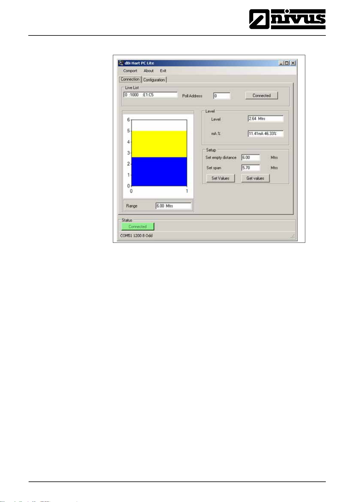
7.4.1 Connection
On the opening screen the following Information is available:
Live List
Gives details of all devices connected, if more than one device is present the
‘Live List’ will become a drop down box and the required device selected.
Poll Address
Gives the Poll Address of the selected Device.
Level
Gives value of the Level in the vessel in Measurement Units (P104)
mA %
Gives current value of the mA Output and how full the vessel is in percentage.
Set Empty Distance
Allows the Empty Distance to be set.
Set Span
Allows the Span to be set which will determine the range of the 4 to 20 mA output, with 4 mA representing 0 % (empty) and 20 mA representing 100 % (full).
Range
Shows the maximum range that can be measured, by the i-Series Intelligent
Sensor, that is currently connected.
Bar Graph Display

®
Instruction Manual
Page 34 i-Series Sensors - Rev. 00 as of 28.09.2012
7.4.2 Configuration
i-Series Sensors
Gives a graphical indication of the Empty Distance (P105) and Maximum Span
(P106) along with current level being measured.
Parameter Get/Set
Get:
Will read and display the current value of the parameter selected along with the
‘units’ of measurement, where used, and the description of the parameter selected. Select the desired parameter form the drop down ‘Parameter’ box and
‘click’ ‘Get’
Set:
Allows the value of the selected parameter to be changed. Select the desired
parameter form the drop down ‘Parameter’ box enter required value in the ‘Value’ box and ‘click’ ‘Set’
For a full list of available parameters see Chapter 5 Parameter Guide.
4 – 20 mA Trim
If the device connected to the mA output is out of calibration, and cannot be calibrated, then the low and high current levels can be trimmed by altering Set 4
mA (P838Low Trim) and Set 20 mA (P839 High Trim). To do this, simply enter
the value that ensures that 4 mA or 20 mA respectively are shown on the remote
device.

Instruction Manual
i-Series Sensors
®
i-Series Sensors - Rev. 00 as of 28.09.2012 Page 35
7.4.3 Communication Port Configuration
If the i-series HART PC Lite fails to connect to the i-Series Intelligent Sensor you
may need to change the communications port that is being used, to do this ‘click’
on the ‘Comport’ menu in the top menu bar and the ‘Comm Port Setup’ window
will appear, select the appropriate communications port and then close the window.
7.5 Parameter Defaults
7.5.1 Factory Defaults
When first installing the i-Series Intelligent Sensor, or subsequently moving or
using the unit on a new application, before proceeding to program the unit for
its intended application it is recommended that you ensure that all parameters
are at their default values by completing a Factory Defaults P930, as described in Chapter 5 Parameter Guide
Once you are satisfied with the installation, and the i-Series Intelligent Sensor is
reading what you would expect in terms of distance from the face of the Sensor
to the material level, then you can proceed with any programming, required for
the intended application. It is sensible to program all of the required parameters
at the same time. The system will be then set-up.

®
Instruction Manual
i-Series Sensors
Page 36 i-Series Sensors - Rev. 00 as of 28.09.2012
8 Getting Results with Your i-Series Intelligent Sensor
This chapter explains how to undertake the various functions of your i-Series Intelligent Sensor. Where specific parameters are used, consult Parameter Guide
in Chapter 9.
8.1 Setting up Your Application
8.1.1 Empty Distance
Empty Distance (P105) is the distance from the face of the Sensor to the material at the bottom of the vessel.
8.1.2 Span
Span (P106) is the distance from the empty level (0 % full) to span (100 % full).
8.1.3 Near and Far Blanking
Near blanking (P107) is the distance from the face of the Sensor that the iSeries Intelligent Sensor will not record a level nearer than. A typical reason to
increase this from the default value would be if you wish to ignore close in obstructions.
Far blanking (P108) is the distance (as a percentage of empty level) beyond the
empty level that the i-Series Intelligent Sensor will read, the default is plus 20%
of empty level. If you wish to monitor further than the empty level, then increase
this figure, so that the empty level plus the far blanking figure (as % of empty
level) is greater than the surface being measured, within the capability of the
Sensor being used.
8.2 Using the 4-20 mA Output
The mA output can be used to monitor remotely what the i-Series Intelligent
Sensor is measuring, so it can be displayed remotely, integrate d into a PLC, or
used to generate a record using a chart recorder or similar.
By default, the i-Series Intelligent Sensor will provide a 4-20 mA output that is
proportional to level and can be overwritten as follows.
By default, the 4-20 mA will represent the operational span of the i-Series model
in use, with empty (0 % full) = 4 mA and full (100 % of the operational span) = 20
mA, but you may wish to only represent a section of the operational span. For
example, the application may have an operational span of 6 metres, but you
may only wish to represent empty level to 5 metres. If so, change P834 (Low
Value) to 0, and P835 (High Value) to 5.0.
If the device connected to the mA output is out of calibration, and cannot be calibrated, then the low and high current levels can be trimmed by altering P838
(Low Trim) and P839 (High Trim). To do this, simply enter the value that ensures
that 4 mA or 20 mA respectively are shown on the remote device. You can use
the left/right menu keys to alter the value until the correct reading is shown on
the remote device, rather than typing in a value.

Instruction Manual
i-Series Sensors
®
i-Series Sensors - Rev. 00 as of 28.09.2012 Page 37
8.3 Setting Security Passcodes
A passcode is used to protect parameter entries and will be required when accessing parameters with certain PC Software’s.
You can set a new passcode to prevent anyone changing any of your settings
within your i-Series Intelligent Sensor. The default passcode is 1997, but this
may be changed as follows.
Additional Information
The passcode is also used for remote access using certain PC Software’s, so
8.3.1 Changing the Passcode
if this is being used, be sure to ensure any additional equipment using this
feature is changed accordingly.
You can set the passcode to any number from 0000 to 9999. To do this, select
P922 which is the passcode parameter which can be changed as required.
8.4 Resetting Factory Defaults
If you need to restore parameters to their original factory settings, then access
parameter P930, which is the factory defaults parameter, change the value to 1
and ENTER, all parameters, with the exception of the mA trims, will be restored
to the factory settings (including the DATEM trace) and on completion.
8.5 Checking the Information Specific to your i-Series Intelligent Sensor
There are some parameters dedicated to each individual i-Series Intelligent
Sensor, such as the software revision and the unit’s s e r ial num ber .
8.5.1 Checking the Software Revision and Serial Number
If you need to identify the serial number of the unit or the current level of software in your i-Series Intelligent Sensor, the following parameters can be used.
Select parameter P926 to view the identity of the current software revision or
P928 for the serial number of the unit.

®
Instruction Manual
Page 38 i-Series Sensors - Rev. 00 as of 28.09.2012
Option
Description
1 = Distance Display
shows the distance from the Sensor face to the
2 = Level (Default)
Display shows how full the vessel is.
3 = Space
Display shows how empty a vessel is.
4 = Volume
Display shows volume of material in the vessel
Option
Description
1 = Liquid (Default)
Use for liquids and flat solid materials
2 = Solid
Solid material that is heaped or at an angle
3 = Closed Tank
Use for closed tanks or domed roofs.
Option
Description
1 = metres
All units of measure are METRES
2 = cm
All units of measure are CENTIMETRES
3 = mm
All units of measure are MILLIMETRES
4 = feet
All units of measure are FEET
5 = inches
All units of measure are INCHES
9 Parameter Guide
9.1 Parameter Listing
9.2 Application
9.2.1 Operation
P100 Mode of Operation
i-Series Sensors
This chapter describes all of the parameters contained within the i-Series
(HART) Intelligent Sensor.
This parameter sets the mode of operation, when in run mode, and can be set to
one of the following:
surface.
P102 Material
9.2.2 Distances
P104 Measurement Units
P105 Empty Level
This parameter should be set to the type of material being monitored.
This parameter sets the units you want to use for programming and display
This parameter is to be set to the maximum distance from the face of the Sensor
to the empty point, in P104 Measurement Units. Note this value affects span as
well, so should be set before span. Default: i-3=3.00 m (9.84 feet),
i-6=6.00 m (19.69 feet), i-10=10.00 m (32.81 feet) and i-15=15.00 m (49.21 feet).

Instruction Manual
i-Series Sensors
®
i-Series Sensors - Rev. 00 as of 28.09.2012 Page 39
Version
Near Blanking Distance
i-3 metre
Default Blanking Distance = 0.125 m (0.66 feet)
i-6 metre
Default Blanking Distance = 0.3 m (0.98 feet)
i-10 metre
Default Blanking Distance = 0.3 m (0.98 feet)
i-15 metre
Default Blanking Distance = 0.5 m (1.64 feet)
P106 Span
P107 Near Blanking Distance
This parameter should be set to the maximum distance from the Empty Level
(P105) to the maximum material level. It is automatically set to be equal to the
Empty Level (P105) less the Near Blanking distance (P107), when you set the
empty level. Default i-3 = 2.80 m (9.19 feet), i-6 = 5.70 m (18.70 feet), i-10 =
9.70 m (31.82 feet) and i-15 = 14.5 m (47.57)
This parameter is the distance from the face of the Sensor that is not measurable, and is pre-set to the minimum value dependant on the version of i-Series Intelligent Sensor being used. It should not be set to less than this figure, but can
be increased.
P108 Far Blanking Distance
Data Logs
9.2.3 Temperature
P580 Minimum Temperature
This is the distance (as a percentage of empty level) beyond the empty point
that the unit will be able to measure, and the default is pre-set to 10 % of the
empty level.
If the surface being monitored can extend beyond the Empty Level (P105) then
the far blanking distance can be increased to a maximum of 100 % of empty
level.
This parameter is always entered as a % of empty level.
The data log parameters contains the following information.
The following parameters give information on temperature conditions seen by
the Temperature source (P852) in ºC. All of these parameters are read only and
cannot be changed, though if P852 is changed they will be reset.
This parameter displays the minimum temperature recorded.
P581 Minimum Temperature Date
This parameter displays the date when the minimum temperature was recorded.
P582 Minimum Temperature Time
This parameter displays the time when the minimum temperature was recorded.
P583 Maximum Temperature
This parameter displays the maximum temperature recorded.

®
Instruction Manual
Page 40 i-Series Sensors - Rev. 00 as of 28.09.2012
P584 Maximum Temperature Date
This parameter displays the date when the maximum temperature was recorded.
P585 Maximum Temperature Time
This parameter displays the time when the maximum temperature was recorded.
P586 Current Temperature
This parameter displays the current temperature.
9.2.4 Sensor Power Information
The following parameters provide information on when the i-Series Intelligent
Sensor was last powered d o wn and how long it had ru n for.
P940 Number of Starts
This parameter displays the number of times that the unit has been powered
since leaving the factory.
i-Series Sensors
P941 Last Power Off Date
This parameter displays the last date on which the power was removed from the
unit.
P942 Last Power Off Time
This parameter displays the last time on which the power was removed from the
unit.
P943 Last Run Time (minutes)
This parameter displays how long the unit had been running, in minutes, prior to
the last power down.
P944 Last Run Time (hours)
This parameter displays how long the unit had been running, in hours, prior to
the last power down.
P945 Total Runtime (hours)
This parameter displays the accumulated total number of hours that the unit has
been in operation (powered up) since leaving the factory.

Instruction Manual
i-Series Sensors
®
i-Series Sensors - Rev. 00 as of 28.09.2012 Page 41
Vessel Shape
P600 Value
Dimensions Required
P600 = 0 Cylindrical Flat base (Default)
Cylinder diameter
P600 = 1 Rectangular Flat base
Width and Breadth
P600 = 2 Cylindrical Cone base
Cylinder diameter and
P600 = 3 Rectangular Pyramid base
Width and Breadth of rec-
P600 = 4 Cylindrical Parabola base
Cylinder diameter and
P600 = 5 Cylindrical Half-sphere base
Cylinder Diameter
P600 = 6 Cylindrical Flat sloped base
Cylinder diameter and
P600 = 7 Rectangular Flat sloped base
Width and Breadth of recP600 = 8 Horizontal cylinder with flat ends
Cylinder diameter and tank
P600 = 9 Horizontal cylinder with parabolic
Cylinder diameter, length of
9.3 Volume
9.3.1 Conversion
P600 Vessel Shape
This parameter determines which vessel shape is used when utilising “Volume
Conversion”.
The choices are as shown in the table below, along with the dimensions that are
required to be entered (P601-P603).
height of bottom
tangular section and height
of bottom
height of bottom
height of bottom
tangular section and height
of bottom
length
ends
one end section, and tank
length

®
Instruction Manual
i-Series Sensors
Page 42 i-Series Sensors - Rev. 00 as of 28.09.2012
Vessel Shape
P600 Value
Dimensions Required
P600 = 10 Sphere
Sphere diameter
P600 = 11 Universal Linear
No dimensions required,
P600 = 12 Universal Curved
No dimensions required,
Vessel Shape
P601
P602
P603
P600 = 2
P600 = 10
level and volume breakpoints used.
level and volume breakpoints used.
P601-P603 Vessel Dimen sion s
These three parameters are used to enter the dimension required to calculate
the volume. The dimensions required are as shown below.
P600 = 0
Cylindrical Flat base
P600 = 1
Rectangular Flat base
Cylindrical Cone base
P600 = 3
Rectangular Pyramid
base
P600 = 4
Cylindrical Parabola
base
P600 = 5
Cylindrical Half-sphere
base
P600 = 6
Cylindrical Flat sloped
base
P600 = 7
Rectangular Flat
sloped base
P600 = 8
Horizontal cylinder with
flat ends
Cylinder Diameter
Width of rec-
Height of base Cylinder Di-
Height of base Width of rec-
Height of base Cylinder Di-
Cylinder Diameter
Height of base Cylinder Di-
Height of base Width of rec-
Length of Cylinder
tangle
ameter
tangle
ameter
ameter
tangle
Cylinder Diameter
Breadth of
rectangle
Breadth of
rectangle
Breadth of
rectangle
P600 = 9
Horizontal cylinder with
parabolic ends
Sphere
P604 Calculated Volume
Length of Cylinder
Sphere Diameter
Cylinder Diameter
Length of one
end section

Instruction Manual
i-Series Sensors
®
i-Series Sensors - Rev. 00 as of 28.09.2012 Page 43
Option
Description
0 = No Units
Volume will be totalised with no units
1 = Tons
Volume will be totalised in Tons
2 = Tonnes
Volume will be totalised in Tonnes
3 = Cubic metres
Volume will be totalised in cubic metres
4 = Litres
Volume will be totalised in litres
5 = UK Gallons
Volume will be totalised in UK Gallons
6 = US Gallons
Volume will be totalised in US Gallons
7 = Cubic feet
Volume will be totalised in cubic feet
8 = Barrels
Volume will be totalised in barrels
P605 Volume Units
This parameter displays the maximum volume that has been calculated by the iSeries Intelligent Sensor and is a Read Only parameter. The volume displayed
will be shown in cubic meters and is the total volume available between empty
level (P105) and 100% of span (P106).
This parameter determines the units that will be used in calculating volume conversion. It is used in conjunction with P607 (maximum volume), please note that
there is no provision for the volume units descriptor to be shown on the display.
The choices are:
P606 Correction Factor
P607 Max Volume
9.3.2 Breakpoints
P610-P641 Level/Volume Breakpoints
This parameter is used to enter a correction factor, when required, such as the
specific gravity of the material so that the volume calculated is relative to the actual amount of material that can be contained between empty level (P105) and
100% of span (P106). Default = 1
This parameter displays the actual maximum volume that has been calculated
by the i-Series Intelligent Sensor, i.e. P604 Calculated Volume x P606 Correction Factor, and is a Read Only parameter. The volume displayed will be shown
in P605 Volume Units and is the total volume available between empty level
(P105) and 100% of span (P106).
These parameters are used to create a profile of the vessel when P600 = 11
(universal linear) or P600 = 12 (universal curved). You should enter breakpoints
in pairs, a reading for level and its corresponding volume. The more pairs you
enter, the more accurate the profile will be. In the case of universal linear, then
enter the level/volume at each of the points where the vessel changes shape. In
the case of the universal curved, enter values around each arc tangent, as well
as at the top and bottom.
You must enter at least two pairs, and you can enter up to 16 pairs.

®
Instruction Manual
i-Series Sensors
Page 44 i-Series Sensors - Rev. 00 as of 28.09.2012
Level
Volum
Level
Volum
Universal Linear (P600 = 11)
This volume calculation creates a linear approximation of the level/volume relationship, and works best if the vessel has sharp angles between each section.
You should enter a level/volume breakpoint for each place where the vessel
changes direction, and numerous where the section is slightly curved (mostly
linear, but has got a small arc). You can enter any number of pairs between 2
and 16.
Universal Curved (P600 = 12)
This volume calculation creates a curved approximation of the level/volume relationship, and works best if the vessel is non-linear, and there are no sharp angles.
You should enter 2 level/volume breakpoints at the minimum and maximum levels, and several for each place where the vessel has got an arc. You can enter
any number of pairs between 2 and 16.
P696 Reset Breakpoints
This parameter allows the resetting, to the default value, of all previously set
breakpoints (P610-673), without having to access them individually. When it is
necessary to reset or amend particular breakpoints this can be achieved by directly accessing the desired parameter (P610-673) and changing as required.
P697 Number of Breakpoints Set
This parameter allows you to review the number of breakpoints that have been
set, without the need to access each individual one in turn, this is a “Read Only “
parameter and no values can be entered.

Instruction Manual
i-Series Sensors
®
i-Series Sensors - Rev. 00 as of 28.09.2012 Page 45
Option
Description
1 = Known (Default)
Remain at the last known value
2 = High
Will fail to the high value (100 % of Span)
3 = Low
Will fail to the low value (empty)
9.4 mA Output
P834 mA Low Level
P835 mA High Level
P838 mA Low Trim
This parameter sets, in Measurement Units (P104), the value of ‘level’, ‘distance’
or ‘space’, depending on the selected Mode of Operation (P100), at which 4 mA
will occur.
This parameter sets, in Measurement Units (P104), the value of ‘level’, ‘distance’
or ‘space’, depending on the selected Mode of Operation (P100), at which 20
mA output will occur.
If the device you are connected to is not calibrated, and not showing the low value, then you can trim it using this parameter. You can either type in the offset directly, or use the arrow keys to move the output up and down until you get the
expected result on the device that is connected.
P839 mA High Trim
If the device you are connected to is not calibrated, and not showing the high
value, then you can trim it using this parameter. You can either type in the offset
directly, or use the arrow keys to move the output up and down until you get the
expected result on the device that is connected.
P808 Fail-safe Mode
By default, if a fail-safe condition occurs, then the display, relays and the mA
output are held at their last known values until a valid r ead ing is obtai ne d.
If required, then you can change this so that the unit goes to high (100% of
span), or low (empty) as follows:
P809 Fail-safe Time
In the event of a fail-safe condition occurring the fail safe timer determines the
time before fail-safe mode is activated. Default = 2.00 mins
If the timer activates, the unit goes into fail-safe, as determined by P808, (Display and P840 (mA Output). When this happens, you will see the message
“LOE!” on the display.
When a valid measurement is obtained then the display, relays and mA output
will be restored and the timer is reset.

®
Instruction Manual
Page 46 i-Series Sensors - Rev. 00 as of 28.09.2012
Option
Description
1 = Internal (Default)
Always uses temperature reading from Sensor.
3 = Fixed
Always uses fixed temperature (P854)
Gas
Sound Velocity
Chlorine
206 m/sec
Argon
308 m/sec
Oxygen
316 m/sec
Air
331.5 m/sec
Ammonia
415 m/sec
Methane
430 m/sec
Helium
435 m/sec
Neon
965 m/sec
9.5 Compensation
P851 Measurement Offset
The value of this parameter is added to the measured distance, in Measurement
Units (P104).
This Offset will be added to the level, as derived from the Sensor, and will affect
everything including the reading on the display, the relay setpoints and the mA
output.
P852 Temperature Source
Default = 1
This parameter determines the source of the temperature measurement. By default it is set to internal Sensor (P852 = 1), which will automatically detect the
temperature from the Sensor. If for any reason, no temperature input is received,
then the Fixed Temp value is used, as set by P854.
The temperature source can be specifically set as follows:
i-Series Sensors
P854 Fixed Temperature
This parameter sets the temperature, in degrees centigrade to be used if
P852 Temperature Source = 3 (Default = 20 °C)
P860 Sound Velocity
This option allows for the velocity of sound to be changed accordin g to the
atmosphere the Sensor is operating in. By default the velocity is set for
342.72 m/sec which is the speed of sound travelling in air at a temperature of
20°C.
The table below gives details of the velocity of sound in various gaseous atmospheres In all cases the velocity indicated is that in a 100% gaseous atmosphere
at 0°C. In atmospheres less than 100 % it may be necessary to check the level
indicated at near empty and near full and compare with the actual level, several
times, then adjust the Sound Velocity accordingly to obtain an accurately displayed reading.

Instruction Manual
i-Series Sensors
®
i-Series Sensors - Rev. 00 as of 28.09.2012 Page 47
P645 Vapour Temperature Compensation
9.6 Stability
9.6.1 Damping
P870 Fill Damping
The sound velocity in air increases or decreases at a uniform rate of
60 cm/sec. per °C, however in atmospheres other than air it will change at a different rate.
This option allows the rate of change in cm/sec. per °C to be set according to the
atmosphere and temperature present. The level indicated, should be compared
with the actual level, several times, then Vapour Temperature Compensation adjusted accordingly, to obtain an accurately displayed reading.
Default = 60 cm/sec. per °C
Damping is used to damp the display, to enable it to keep up with the process
but ignore minor surface fluctuations.
P871 Empty Damping
9.6.2 Filters
P881 Fixed Distance
P884 Peak Percentage
This parameter determines the maximum rate at which the unit will respond to
an increase in level. It should be set slightly higher than the maximum vessel fill
rate. Default = 10.000 metres/minute (32.81 feet/minute)
This parameter determines the maximum rate at which the unit will respond to a
decrease in level. It should be set slightly higher than the maximum vessel empty rate. Default = 10.000 metres/minute (32.81 feet/minute)
This parameter determines the width of gate to be used in tracking an echo and
under normal circumstances will not require changing, but it can be increased in
the cases where the surface is moving extremely fast (in excess of 10 m/min) to
ensure smooth processing of the changing level.
When P102 = 2 (Solids), this parameter can be used to determine the point at
which the measurement is taken, within the established gate of the selected
echo, in order to compensate for any error that maybe caused by “angles of repose” presented by the way the material settles. Please consult NIVUS GmbH,
for further information and assistance on changing the value of this parameter.

®
Instruction Manual
Page 48 i-Series Sensors - Rev. 00 as of 28.09.2012
9.7 System
The following three parameters do not affect how the unit performs, but details,
contained in them, may be required, by NIVUS GmbH, when making technical
enquiries.
9.7.1 Password
P921 Enable Code
Enables the passcode (P922), which means the passcode must be entered to
go into program mode. If disabled (set to 0), then no passcode is required, and
pressing ESC and ENTER button simultaneously will allow entry into the program mode.
P922 Passcode
This is the passcode that must be used to enter program mode. The default is
1997, but this can be changed to another value.
9.7.2 System Information
i-Series Sensors
P926 Software Revision
P927 Hardware Revision
P928 Serial Number
P930 Factory Defaults
9.7.3 Date & Time
P931 Date
This parameter will display the current software revision.
This parameter will display the current hardware revision. It is read only, and
cannot be changed.
This parameter will display the serial number of the unit.
This parameter resets all parameter values to the original Factory Set values
that were installed when the unit was tested, before despatch to you.
To reset parameters, Set P930 to 1.
The date and time is used, to control specific relay functions and date stamp certain events that are contained in the Data Logs. It is also used in conjunction
with the system watchdog that keeps an eye on the times the unit has started.
This parameter display the current date, in the format as set by P933 (Date
Format), and can be reset if required.
P932 Time
This parameter displays the current time and can be reset if required, in the format HH:MM (24-hour format). This is set initially to UTC.

Instruction Manual
i-Series Sensors
®
i-Series Sensors - Rev. 00 as of 28.09.2012 Page 49
Option
Description
9.7.4 LOE Save Trace
P950 Save DATEM Trace on LOE
When enabled this parameter will ensure that in the event of the unit going into a
LOE situation a trace at the time of the LOE occurrence is saved for future reference.
0 = Off Feature is disabled and in the event of LOE echo
trace will NOT be saved.
9.8 DATEM
P020 Set DATEM
P021 Set Dist
1 = Enable (Single
Trace)
2 = Enable Overwrite
(Default)
This parameter allows DATEM to be reset to its default value. To reset DATEM
to its default value set parameter value to 1, the trace will then be set to its default value and then update as normal.
Allows the user or service personnel to determine which echo is to be displayed.
On start-up, if the unit displays an incorrect reading then simply enter the distance from the Sensor to the required level and, if an echo is present at this
point, the Gate will establish itself around the chosen echo, DATEM will update
in front of the Gate and reference out any other unwanted echoes.
It should be noted that DATEM will reset to default values whilst performing this
function, and reform itself once it has selected an ec ho .
Enter distance from the face of Sensor to the t arget in units of measurement
P104
Values: Min. 0.0 00, Max. 99. 0 0 m
In the event of a LOE situation an echo trace WILL
be saved and stored for future reference. Once a
LOE trace has been saved no further traces will be
taken
In the event of an LOE event occurring any previous trace will be overwritten and the last LOE trace
saved.
P905 Peak Clearance
This parameter is used to set the “height” above which the DATEM trace will
“stand off” from around unwanted echoes such as obstructions. Please consult
NIVUS GmbH for further information and assistance on changing the value of
this parameter.
P906 Side Clearance
This parameter is used to set the “distance” by which the DATEM trace will
“stand off” from around unwanted echoes such as obstructions. Please consult
NIVUS GmbH for further information and assistance on changing the value of
this parameter.

®
Instruction Manual
Page 50 i-Series Sensors - Rev. 00 as of 28.09.2012
Symptom
What to Do
10 Troubleshooting
i-Series Sensors
This section describes many common symptoms, with suggestions as to what to
do.
Sensor not firing. Check power supply
Unit indicates a “L0E”
situation.
Incorrect reading being
obtained for current
level.
4-20 mA current fixed
even though level is
changing.
Material level is consistently incorrect by the
same amount.
No valid echo being received and unit has gone
into fault condition. Check material level is not out
of range, sensor is perpendicular to material surface.
Measure actual distance from Sensor face to surface of material. Access P21, via PC Software type
in the measured distance, and Set Parameter.
Poll address is above 0, and is in multi drop mode.
Check empty level (P105) correctly entered.

Instruction Manual
i-Series Sensors
®
i-Series Sensors - Rev. 00 as of 28.09.2012 Page 51
Parameter Details
Entered Values
No.
Description
Default
1 2 3 4 5
P100
Mode
2 = Level
P102
Material
1 = Liquid
P105
Empty Level
Model Dependant
P106
Span
Model Dependant
P107
Near Blanking
Model Dependant
P108
Far Blanking
20%
Parameter Details
Entered Values
No.
Description
Default
1 2 3 4 5
P580
Minimum Temper-
Read Only
P581
Min Temperature
Read Only
P582
Min Temperature
Read Only
P583
Maximum Tem-
Read Only
P584
Max Temperature
Read Only
P585
Max Temperature
Read Only
P586
Current Tempera-
Read Only
Parameter Details
Entered Values
No.
Description
Default
1 2 3 4 5
P940
Number of Starts
Read Only
P941
Last Power Off
Read Only
P942
Last Power Off
Read Only
Last Runtime
Minutes
P944
Total Runtime
Read Only
Parameter Details
Entered Values
No.
Description
Default
1 2 3 4 5
P600
Vessel Shape
0
P601
Vessel Dimen-
0.00
P602
Vessel Dimen-
0.00
P603
Vessel Dimen-
0.00
P604
Calculated Vol-
Read Only
P605
Volume Units
Model Dependant
P606
Correction Fac-
1
P607
Max Volume
Read Only
11 Parameter Record
Application
P104
Measurement
Units
Data Logs
Temperature
P581
ature
Date
Time
perature
Date
Time
Model Dependant
ture
Sensor Power Information
P943
Volume
Conversion
Read Only

®
Instruction Manual
Page 52 i-Series Sensors - Rev. 00 as of 28.09.2012
Parameter Details
Entered Values
No.
Description
Default
1 2 3 4 5
P610
Level Breakpoint 1
0.00
P611
Volume Breakpoint 1
0.00
P612
Level Breakpoint 2
0.00
P613
Volume Breakpoint 2
0.00
P614
Level Breakpoint 3
0.00
P615
Volume Breakpoint 3
0.00
P616
Level Breakpoint 4
0.00
P617
Volume Breakpoint 4
0.00
P618
Level Breakpoint 5
0.00
P619
Volume Breakpoint 5
0.00
P620
Level Breakpoint 6
0.00
P621
Volume Breakpoint 6
0.00
P622
Level Breakpoint 7
0.00
P623
Volume Breakpoint 7
0.00
P624
Level Breakpoint 8
0.00
P625
Volume Breakpoint 8
0.00
P626
Level Breakpoint 9
0.00
P627
Volume Breakpoint 9
0.00
P628
Level Breakpoint 10
0.00
P629
Volume Breakpoint
0.00
P630
Level Breakpoint 11
0.00
P631
Volume Breakpoint
0.00
P632
Level Breakpoint 12
0.00
P633
Volume Breakpoint
0.00
P634
Level Breakpoint 13
0.00
P635
Volume Breakpoint
0.00
P636
Level Breakpoint 14
0.00
P637
Volume Breakpoint
0.00
P638
Level Breakpoint 15
0.00
P639
Volume Breakpoint
0.00
P640
Level Breakpoint 16
0.00
P641
Volume Breakpoint
0.00
P696
Reset Breakpoints
0
P697
Number of B’points
Read
Parameter Details
Entered Values
No.
Description
Default
1 2 3 4 5
P834
Low Level
0.000
P835
High Level
Model Dependant
P838
Low Trim
0.00 mA
P839
High Trim
0.00 mA
P808
Fail Mode
1 = Known
P809
Fail Time
2.0 mins
Parameter Details
Entered Values
P808
Fail Mode
1 = Known
P809
Fail Time
2.0 mins
Breakpoints
i-Series Sensors
mA Output
Output
Fail Mode

Instruction Manual
i-Series Sensors
®
i-Series Sensors - Rev. 00 as of 28.09.2012 Page 53
Parameter Details
Entered Values
No.
Description
Default
1 2 3 4 5
P851
Measurement
0.000
P852
Temperature
1 = Automatic
P854
Fixed Tempera-
20.00 Deg. C
P860
Sound Velocity
342.72 m/sec
P645
Vapour Temp.
60 cm/sec per
Parameter Details
Entered Values
No.
Description
Default
1 2 3 4 5
P870
Fill Damping
Model De-
P871
Empty Damping
Model De-
Parameter Details
Entered Values
No.
Description
Default
1 2 3 4 5
P881
Fixed Distance
0.2 metre
P884
Peak Percentage
50%
Parameter Details
Entered Values
No.
Description
Default
1 2 3 4 5
P921
Enable Code
1 = Yes
P922
Passcode
1997
P926
Software Revi-
Read Only
P927
Hardware Revi-
Read Only
P928
Serial Number
Read Only
P950
Save Trace on
2
Parameter Details
Entered Values
No.
Description
Default
1 2 3 4 5
P905
Peak Clearance
80 millivolts
P906
Side Clearance
0.06 metres
Compensation
Stability
Damping
Filters
System
DATEM

®
Instruction Manual
Page 54 i-Series Sensors - Rev. 00 as of 28.09.2012
12 Maintenance and Cleaning
During standard use the NivuMaster sensor does not get in contact with the
measurement medium and therefore is virtually maintenance-free. If the sensor
face however should get dirty due to medium contact (immersion) or ambient
conditions (dust) clean the sensor face carefully with a damp cloth.
Never use aggressive cleansing agents (such as thinner). For heavy pollution
NIVUS recommends the use of surface-active agents. The use of abrasive
cleansing agents is not allowed.
If you wish to clean or dismantle the sensor please disconnect the unit from
mains before.
No hard objects such as wire brushes, rods, scrapers or similar shall be used to
clean the sensor. Using a high pressure cleaner may lead to sensor damage
and measurement failures and thus is not allowe d.
In various countries it may be necessary to carry out regular maintenance with
comparative measurements in particular applications to comply with official regulations. If desired, NIVUS is going to carry out all required verifications, h ydrau lic
and technical assessment, calibration, troubleshooting and repairs if an according maintenance agreement has been contracted. These services will be carried
out according to DIN 19559 incl. the agreed proof of the remaining residual error, as well as according to rules in the respective countries.
i-Series Sensors
13 Emergency
In case of emergency
- press the emergency-off button of the main system or
- set the slide switch on the unit to OFF.
14 Dismantling/Disposal
The device shall be disposed according to the local regulations for electronic
products.

Instruction Manual
i-Series Sensors
®
i-Series Sensors - Rev. 00 as of 28.09.2012 Page 55
15 Table of Pictures
Fig. 2-1 Overview ............................................................................................................................................. 8
Fig. 3-1 Ex-label zone 0 i-sensors .................................................................................................................. 12
Fig. 3-2 Ex-label zone 1 i-sensors .................................................................................................................. 12
Fig. 4-1 Type key for i-Series Intelligent Sensors .......................................................................................... 14
Fig. 6-1 i-03 sensor dimensions ..................................................................................................................... 18
Fig. 6-2 i-06 and i-10 sensor dimensions ....................................................................................................... 18
Fig. 6-3 i-15 sensor dimensions ..................................................................................................................... 19
Fig. 6-4 Sensor dimens ions i-03 and i-06, front tread mount ......................................................................... 19
Fig. 6-5 Sensor dimensions i-10, front tread mount ....................................................................................... 20
Fig. 7-1 Time in seconds between firing ......................................................................................................... 30

®
Instruction Manual
Page 56 i-Series Sensors - Rev. 00 as of 28.09.2012
16 Index
i-Series Sensors
C
Cleaning 54
Comparative Measurements 54
Connections 13
Copyright 3
D
Danger by electric voltage 11
Danger Notes 11
Declaration of Conformity 6
Delivery 16
Device Identification 12
Device Versions 14
DIN 19559 54
Documentation 16
E
Ex-Protection 9
F
Functional Principle 14
N
Names 3
Notes 11
O
Operating Permits 13
Overview 8
P
Parts subject to wear and tear 13
R
Receipt 16
Requirements 9
Return 16
S
Sensor
Dimensions 18
Storing 16
I
Installation 17
M
Maintenance 54
Maintenance Agreement 54
T
Translation 3
Transport 16
Turn-off procedure 13
Type key 14
W
Warnings 11

NIVUS Gmb H
Désignation:
"Ex" Capteurs ultrasoniques de la série i
EU Konformitätserkl är ung
EU Declaration of Conformity
Déclaration de conformité UE
DE / EN / FR
Für das folgend bezeichnete Erzeugnis:
For the following product:
Le produit désigné ci-dessous:
Im Täle 2
75031 Eppingen
Telefon: +49 07262 9191-0
Telefax: +49 07262 9191-999
E-Mail: info@nivus.com
Internet: www.nivus.de
Bezeichnung:
Description:
"Ex" Ultraschallsensoren i-Serie
"Ex" i series of ultrasonic transducers
Typ / Type: NMI0xxxxxxx0… / NMI0xxxxxxx1… 1)
erklären wir in alleiniger Verantwortung, dass die auf dem Unionsmarkt ab dem Zeitpunkt der Unterzeichnung
bereitgestellten Geräte die folgenden einschlägigen Harmonisierungsvorschriften der Union erfüllen:
we declare under our sole responsibility that the equipment made available on the Union market as of the date of signature of
this document meets the standards of the following applicable Union harmonisation legislation:
nous déclarons, sous notre
seule responsabilité, à la date de la présente signature, la conformité du produit pour le marché de
l’Union, aux directives d'harmonisation de la législation au sein de l’Union:
• 2014/34/EU • 2014/30/EU • 2011/65/EU
Bei der Bewertung wurden folgende eins c hläg ige har m onisi er te Nor men zugrunde gelegt bzw. wird die Konformität
erklärt in Bezug die nachfolgend genannten anderen technischen Spezifikationen:
The evaluation assessed the following applicable harmonised standards or the conformity is declared in relation to other
technical specifications listed below:
L’évaluation est effectuée à partir des normes harmonisées applicable ou la conformité est déclarée en relation aux autres
spécifications techniques désignées ci-dessous:
• EN 60079-0:2012+A11:2013 • EN 60079-18:2015 • EN 60079-11:2012
• EN 60079-26:2015 • EN 61326-1:2013
Ex-Kennzeichnung / Ex -designation / Marquage Ex :
II 2G Ex mb IIC T4 Gb & II 2D Ex mb IIIC T130°C Db Tamb -40°C to +80°C
II 1G Ex ia IIC T4 Ga & II 1D Ex ia IIIC T130°C Da Tamb -40°C to +80°C
1)
EG-Baumusterprüf bes chei nig ung / EC-Type Examination Certificate / Attestation d'examen «CE» de type:
TRaC12ATEX0031X (Ex mb) TRaC12ATEX0030X (Ex ia)
1)
Benannte Stelle (Kennnummer) / Notified Body (Identif. No.) / Organisme notifié (№ d’identification)
TRaC Global Ltd, 100 Frobisher Business Park, Worcestershire, WR141BX, UK (0891)
Qualitätssicherung ATEX / Quality assurance ATEX / Assurance qualité ATEX:
TÜV Nord CERT GmbH, Am TÜV 1, 30519 Hannover, Allemagne (0044)
Diese Erklärung wird verantwort lic h für den Hers tel ler:
NIVUS GmbH
This declaration is submitted on behalf of the manufacturer:
Le fabricant assume la responsabilité de cette déclaration:
75031 Eppingen
abgegeben durch / represented by / faite par:
Ingrid Steppe (Geschäftsführerin / Managing Director / Directeur général)
Eppingen, den 13.08.2018
Im Taele 2
Allemagne
Gez. Ingrid Steppe
Q:\Formulare\CE…

NIVUS Gmb H
EU Konformitätserkl är ung
EU Declaration of Conformity
Déclaration de conformité UE
DE / EN / FR
Für das folgend bezeichnete Erzeugnis:
For the following product:
Le produit désigné ci-dessous:
Im Täle 2
75031 Eppingen
Telefon: +49 07262 9191-0
Telefax: +49 07262 9191-999
E-Mail: info@nivus.com
Internet: www.nivus.de
Bezeichnung:
Description:
Désignation:
Ultraschallsensoren i-Serie
i series of ultrasonic transducers
Capteurs ultrasoniques de la série i
Typ / Type: NMI0…
erklären wir in alleiniger Verantwortung, dass die auf dem Unionsmarkt ab dem Zeitpunkt der Unterzeichnung
bereitgestellten Geräte die folgenden einschlägigen Harmonisierungsvorschriften der Union erfüllen:
we declare under our sole responsibility that the equipment made available on the Union market as of the date of signature of
this document meets the standards of the following applicable Union harmonisation legislation:
nous déclarons, sous notre seule responsabilité, à la date de la présente signature, la conformité du produit pour le marché de
l’Union, aux directives d'harmonisation de la législation au sein de l’Union:
• 2014/30/EU • 2011/65/EU
Bei der Bewertung wurden folgende eins c hläg ige har m onisi er te Nor men zugrunde gelegt bzw. wird die Konformität
erklärt in Bezug die nachfolgend genannten anderen technischen Spezifikationen:
The evaluation assessed the following applicable harmonised standards or the conformity is declared in relation to other
technical specifications listed below:
L’évaluation est effectuée à partir des normes harmonisées applicable ou la conformité est déclarée en relation aux autres
spécifications techniques désignées ci-dessous:
• EN 61326-1:2013
Diese Erklärung wird verantwort lic h für den Hers tel ler:
This declaration is submitted on behalf of the manufacturer:
Le fabricant assume la responsabilité de cette déclaration:
NIVUS GmbH
Im Taele 2
75031 Eppingen
Allemagne
abgegeben durch / represented by / faite par:
Ingrid Steppe (Geschäftsführerin / Managing Director / Directeur général)
Eppingen, den 13.08.2018
Ingrid Steppe
Gez.
Q:\Formulare\CE…
 Loading...