

Page 1

USER’S
MANUAL
HOOK 3
Page 2

2
NIVIUK GLIDERS C/ DEL TER 6, NAVE D 17165 LA CELLERA DE TER - GIRONA - SPAIN
TEL. +34 972 42 28 78 FAX +34 972 42 00 86
[email protected] www.niviuk.com
HOOK 3
Passion & evolution
WELCOME
We wish to welcome you to our team and thank you for the condence
that you have placed in a NIVIUK Glider.
We would like to share with you the commitment, the passion and emotions
of the Niviuk design team, which have resulted in the creation of the new
HOOK 3. Niviuk are very proud of this new glider, a glider carefully designed
to bring you maximum pleasure whilst allowing you learn and progress.
The HOOK 3 has born from Niviuk essence, our tradition and from
our experience from the past and future’s innovation. Versatile and
ultramodern, the HOOK 3 offers an excellent piloting experience,
adventure to the highest extent, comfort in ight and efciency. It’s the
change from the usual to the extraordinary. The HOOK 3 does not leave
anything else to wish for.
We are condent that you will enjoy ying this wing and that you will soon
understand the meaning of our slogan:
“The importance of small details”
This is the user’s manual that we recommend you to read in detail.
The NIVIUK Gliders Team.
USER’S MANUAL
NIVIUK Gliders HOOK 3
This manual offers all the necessary information that will familiarize you
with the main characteristics of your new paraglider. Although this manual
informs you about your glider, it does not offer the instruction requirements
necessary for you to be able to pilot this type of wing. Flying instruction
can only be taught at a paragliding school recognised by the Flying
Federation of your country.
Nevertheless we remind you that it is important that you carefully read all
the contents of the manual for your new HOOK 3.
Severe injuries to the pilot can be the consequence of the misuse of this
equipment.
Page 3
3
SUMMARY
WELCOME 2
USER’S MANUAL 2
1. CHARACTERISTICS 4
1.1 WHO IS IT DESIGNED FOR? 4
1.2 CERTIFICATION 4
1.3 IN-FLIGHT BEHAVIOUR 4
1.4 ASSEMBLY, MATERIALS 4
1.5 ELEMENTS, COMPONENTS 5
2. UNPACKING AND ASSEMBLY 5
2.1 CHOOSE THE RIGHT PLACE 5
2.2 PROCEDURE 5
2.3 ASSEMBLY OF THE HARNESS 5
2.4 TYPE OF HARNESS 5
2.5 ASSEMBLY OF THE ACCELERATOR 6
2.6 INSPECTION AND WING INFLATION
ON THE GROUND 6
2.7 ADJUSTING THE BRAKES 6
3. THE FIRST FLIGHT 6
3.1 CHOOSE THE RIGHT PLACE 6
3.2 PREPARATION 6
3.3 FLIGHT PLAN 7
3.4 PRE-FLIGHT CHECK LIST 7
3.5 WING INFLATION, CONTROL,
AND TAKE-OFF 7
3.6 LANDING 7
4. IN FLIGHT 7
4.1 FLYING IN TURBULENCE 7
4.2 POSSIBLE CONFIGURATIONS 7
4.3 USING THE ACCELERATOR 9
4.4 FLYING WITHOUT BRAKE LINES 9
4.5 KNOTS IN FLIGHT 9
5. LOSING HEIGHT 10
5.1 EARS 10
5.2 B-LINE STALL 10
5.3 SPIRAL DIVE 11
5.4 SLOW DESCENT TECHNIQUE 11
6. SPECIAL METHODS 11
6.1 TOWING 11
6.2 ACROBATIC FLIGHT 11
7. FOLDING INSTRUCTIONS 12
8. CARE AND MAINTENANCE 12
8.1 MAINTENANCE 12
8.2 STORAGE 12
8.3 CHECKS AND CONTROLS 12
8.4 REPAIRS 12
9. SAFETY AND RESPONSIBILITY 13
10. GUARANTEE 13
11. TECHNICAL DATA 14
11.1 TECHNICAL DATA 14
11.2 MATERIALS DESCRIPTION 15
11.3 RISER ARRANGEMENT 16
11.4 LINE PLAN 17
11.5 LENGTHS HOOK 3 21 18
11.6 LENGHTS HOOK 3 23 18
11.7 LENGHTS HOOK 3 25 19
11.8 LENGHTS HOOK 3 27 19
11.9 LENGHTS HOOK 3 29 20
11.10 CERTIFICATION SPECIMEN 21
Page 4

4
1. CHARACTERISTICS
1.1 WHO IS IT DESIGNED FOR?
The HOOK 3 has been clearly designed for pilots that aim for the best:
independence, freedom and adventure.
At Niviuk we have very clear that the most important element of the
glider is the pilot. That’s why our new HOOK 3 has a single objective:
the personal growth of the pilot. Its high performance and high level
of comfort in ight will let you choose between a ight with a sporty
character or an astonishing serene ight. You are in charge of setting the
pace. Let your emotions soar with the Hook 3.
1.2 CERTIFICATION
The HOOK 3 has successfully achieved the European EN B and the LTF
1-2 certications.
Description of ight characteristics on B class:
Paraglider with good passive safety and forgiving characteristics. High
resistance to departures from normal ight.
Description on pilots skills required on B class:
Designed for all pilots including pilots under all levels of training.
The HOOK 3 passed the essential load test of 8G without experiencing
any problems.
On the ight test all the ve sizes of the HOOK 3 received the best
certication EN B.
This test was carried out in the Swiss Air-Turquoise laboratories.
Check the certication results and gures on the last pages of this manual
or at www.niviuk.com
1.3 IN-FLIGHT BEHAVIOUR
In order to bring you the best glider in this class the NIVIUK Team have
carried out extensive and meticulous design work. As a consequence of
several prototypes and many hours of test ights numerous adjustments
were made. These prototypes were then tested in all types of ight
conditions.
HOOK 3 is the result. Hook 3 is technology privileged compared to
its predecessors, the wing features a new prole with performance
and technologies transmitted down from the competition wings.
Improvements and innovations that Olivier and our R&D team manage to
move from competitions all around the world to the new HOOK 3, for you
to enjoy it. In spite of evolution, the HOOK 3 is a (safe/ EN B ) glider and it
will provide you what is expected of it. Hook 3 is a glider for all pilots who
wish to be equipped with latest performance and technology; it is capable
to offer the same usual safety, the same feeling with closed eyes and the
same coherence with the original NIVIUK ideas.
1.4 ASSEMBLY, MATERIALS
The HOOK 3 does not only introduce new design methods but also new
manufacture technologies. Not a single millimetre of error is possible in
the manufacturing process from Olivier’s computer to the cutting of the
fabric. An automatic process controlled by a laser-cutting program cuts
each of the sections that compose the different parts of the wing. This
program not only cuts the pieces of fabric but it also paints the guideline
marks that will aid the assembly; it also numbers the separate pieces
of material. All this is carried out before human handling of the pieces
begins. So we eliminate possible and understandable errors that may
occur during this delicate procedure.
The lines are semi-automatically manufactured and all the sewing is
nished under the supervision of our specialists. The jigsaw puzzle of the
assembly process is made easier using this method. We minimise the
Page 5

5
processes while making the quality control more efcient. All the different
parts of the canopy are cut and assembled under the strict conditions
induced by the automation of the whole process.
All NIVIUK Gliders go through an extremely thorough and efcient
nal inspection.
Every single line of each glider is measured individually once the nal
assembly has concluded. Each wing is then individually inated for the
last visual revision.
Each glider is packaged following the maintenance and conservation
instructions recommended for the advanced materials. NIVIUK Gliders are
made of rst class materials as demanded by the performance, durability,
and homologation requirements of the present-day market.
Information about construction materials is given on the last pages of
this manual.
1.5 ELEMENTS, COMPONENTS
The HOOK 3 is delivered to its owner together with a series of
components that, although not fundamental, do take an important
part in the use, transport and storage of the paraglider. The glider
is delivered together with a rucksack, large enough for all of the
equipment to t inside, once appropriately packed. The rucksack
is designed to make transport on foot as pleasant as possible. The
internal bag, intended to protect the HOOK 3 from possible damage,
during storage is also supplied.
The glider strap allows you to fold the wing as small as possible.
Furthermore you will nd the accelerator bar that completes the
acceleration gear of the wing, a small fabric repair kit made of auto
adhesive rips top, a user’s manual with the answers all our questions
about our new HOOK 3, an instruction booklet and also a USB pen drive.
2. UNPACKING AND ASSEMBLY
2.1 CHOOSE THE RIGHT PLACE
We recommend that you unpack and assemble your wing on a schooling
slope or a at clear area without too much wind and free of obstacles.
These conditions will allow you to carry out all the steps required for you
to check and inate the HOOK 3.
We recommend that an instructor or a retailer supervises the entire
procedure as only they are competent to resolve any doubt in a safe and
professional way.
2.2 PROCEDURE
Take the paraglider out of the rucksack, open it and spread it open, with
the lines on top of the underside, position the wing as if you were to
inate it. Check the condition of the fabric and the lines, make sure there
are no abnormalities. Check the maillons that attach the lines to the risers
are properly closed. Identify and order the A, B, C lines, the brake lines
and the corresponding risers. Make sure that there are no ties or knots.
2.3 ASSEMBLY OF THE HARNESS
Correctly place the risers on the harness karabiners. The risers and lines
should not have any twists and they should be in the right order. Check
that the harness buckles are correctly locked.
2.4 TYPE OF HARNESS
The HOOK 3 has passed the EN B certication using a EN1651:1999
type harness.
This certication allows it to be own with most of the harnesses on the
market, even the ones that use cocoon.
Page 6

6
We recommend that you adjust the distance of the chest strap according
the homologation from 42 to 50 cm between the harness carabineers.
This adjustment will offer the top compromise between safety and
feelings. Any change made to these specications may affect the wing’s
performance and reactions. This would therefore effect the glider’s
conguration and would not conform to the homologation.
2.5 ASSEMBLY OF THE ACCELERATOR
The acceleration mechanism of the HOOK 3 works when you push with
your feet on the accelerator bar, this is supplied with the equipment.
On delivery the accelerator bar has not yet been installed and it is
recommended that it is t by you before ight. Most harnesses are
equipped with a pre-installed acceleration system. When tting any
accelerator system ensure that all preinstalled items within the harness,
such as roller pulleys are used correctly. After tting, take into account
that you will have to adjust the length of the accelerator lines for correct
use. This will vary according to the length of the pilot’s legs!
We recommend that you try the correct tting of the acceleration system
on equipment designed to do this, most paragliding schools have this sort
of equipment.
2.6 INSPECTION AND WING INFLATION ON THE GROUND
Once you have checked all the equipment and made sure that the
wind conditions are favourable, inate your HOOK 3 as many times as
necessary in order to become acquainted with the wing’s behaviour.
The HOOK 3 inates easily and smoothly. An excess of energy is not
necessary and the wing will inate with minimum pressure on the harness
when you move forward. This may be assisted by using the A lines. Do
not pull on them, just lift to accompany the natural rising movement of
the wing, once the wing is in the 12 o’clock position, simply apply correct
pressure on the brake lines and the HOOK 3 will sit over your head.
2.7 ADJUSTING THE BRAKES
The length of the main brake lines is adjusted at the factory to the length
established during homologation. However, the length can be changed
to adapt to the pilot’s ying style. Nevertheless, we recommend that you
y for a while with these, set at the original length. This will allow you to
become accustomed to the HOOK 3’s original ying behaviour. If you
then decide to change the length of the brake lines, untie the knot, slide
the line through the brake link to the desired length, and strongly re-tie
the knot. Qualied personnel should carry out this adjustment. You must
ensure that this adjustment does not slow down the glider without any
pilot input. Both brake lines should be symmetrical and measure the
same length. The most recommended knots are the clove hitch knot or
bowline knot.
When changing the brakes length, it is necessary to check that they do
not act when the accelerator is used. When we accelerate the glider
rotates over the C riser and the trailing edge elevates. We must check
that the brake is adjusted taking in consideration this extra length in
acceleration.
3. THE FIRST FLIGHT
3.1 CHOOSE THE RIGHT PLACE
We recommend that the rst ight with your HOOK 3 is made on a
smooth slope (a school slope) or in your usual ying area.
3.2 PREPARATION
Repeat the procedures detailed in chapter 2 UNPACKING AND
ASSEMBLY in order to prepare your equipment.
Page 7

7
3.3 FLIGHT PLAN
Draw out a ight plan before take-off in order to avoid possible ight errors.
3.4 PRE-FLIGHT CHECK LIST
Once you are ready, but before you take-off, carry out another
equipment inspection. Ensure correct installation of all equipment and
that all lines are free of hindrances or knots. Check that the weather
conditions are suited for your ying skills.
3.5 WING INFLATION, CONTROL, AND TAKE-OFF
Smoothly and progressively inate the wing (chapter 2.6 INSPECTION
AND WING INFLATION ON THE GROUND). The HOOK 3 inates easily
and does not require excessive energy. It does not tend to over-take you,
so the wing ination phase is carried out without anguish. These take off
characteristics provide a perfect control phase and enough time for the
pilot to decide whether to accelerate and take off.
Whenever the wind speed allows it, we recommend a reverse launch
technique; this type of launch allows you to carry out a better visual check
of the wing. The HOOK 3 is especially easy to control in this position in
strong winds. However, wind speeds up to 25 to 30 km/h are considered
strong and extra consideration should be given to any thought of ight.
Preparation and positioning of the wing on the take off is especially
important. Choose a location which is appropriate for the direction of the
wind. Position the paraglider as if it were part of a large circle, taking into
account the shape of the canopy in ight. All this will assist in a trouble
free take-off.
3.6 LANDING
The HOOK 3 lands excellently, it transforms the wing speed into lift on the
pilot’s demand, allowing an enormous margin of error. You will not have to
wrap the brake lines around your hand to get greater braking efciency.
4. IN FLIGHT
4.1 FLYING IN TURBULENCE
The HOOK 3 complies with an excellent homologation to face this type
of situation with the best safety guarantee. This wing is stable in all types
of weather conditions. It reacts admirably in passive ight, thus offering
a high level of safety in turbulent conditions. Nonetheless, all paragliders
always have to be piloted according to the prevailing weather conditions;
the pilot is the ultimate safety factor.
We recommend that the pilot adopts a proactive attitude when ying,
making the necessary ne adjustments to keep the wing in control. He/
she should stop braking to allow it to y at the required wing speed after
a correction is made. Do not maintain any correction for longer than
necessary (braked) this would cause the wing to enter into critical ying
situation. Whenever necessary, control a situation, react to it and then reestablish the required speed.
4.2 POSSIBLE CONFIGURATIONS
We recommend that training to master these manoeuvres be carried out
under the supervision of a competent school.
Asymmetric collapse
In spite of the great stability of the prole of the HOOK 3, heavy turbulent
conditions may cause part of the wing to collapse asymmetrically. This
usually happens when the pilot has not foreseen this possible reaction
Page 8

8
of the wing. When the wing is about to experience an asymmetric
collapse the brake lines and the harness will transmit a loss of pressure
to the pilot. To prevent the collapse from happening, pull the brake line
corresponding to the compromised side of the wing, this will increase the
angle of incidence. If the collapse does happen the HOOK 3 will not react
violently, the turn tendency is very gradual and it is easily controlled.
Lean your body towards the side that is still ying in order to counteract
the turn and to maintain a straight course, if necessary slightly slow
down the same side. The collapse will normally open by itself but if that
does not happen, pull completely on the brake line on the side which has
collapsed (100%). Do this with a rm movement. You may have to repeat
this operation to provoke the re-opening. Take care not to over-brake on
the side that is still ying (turn control) and when the collapse has been
solved; remember to let the wing recover its ying speed.
Symmetric collapse
In normal ying conditions the design of the HOOK 3 ensures that a
symmetric collapse is quite improbable. The prole of the wing has been
designed to widely tolerate extreme changes in the angle of incidence.
A symmetric collapse may occur in heavy turbulent conditions, on entry
or exit of strong thermals or lack of adapting the use of the accelerator
to the prevailing air conditions. Symmetrical collapses usually re-inate
without the glider turning but you can symmetrically apply the brake
lines with a quick deep pump to quicken the re-ination. Release the
brake lines immediately to recover optimum ight speed.
Negative spin
This conguration is out of the normal ight behaviour of the HOOK
3. Certain circumstances however, may provoke this conguration
such as trying to turn when the wing is ying at very low speed (while
heavily braking). It is not easy to give any recommendations about this
situation since it varies depending on the circumstances. Remember
that you should restore the relative air speed over the wing. To achieve
this, progressively reduce the pressure on the brake lines and let the
wing gain speed. The normal reaction would be a lateral surge with a
turn tendency no greater than 360º before restoring to normal ight
conditions.
Parachutal stall
The possibility of this happening has been eliminated by the design of the
HOOK 3 and it is highly unlikely to happen on this paraglider. If it does
happen, the feeling would be that the wing would not be advancing; you
would feel a kind of instability and a lack of pressure on the brake lines,
although the canopy would appear to be correctly inated. The correct
reaction would be to release the pressure on the brake lines and push the
A lines forward or rather lean your body to any side WITHOUT PULLING
ON THE BRAKE LINES.
Deep Stall
The possibility of the HOOK 3 falling into this conguration is almost
nonexistent, if the factory settings have not been altered. This could
happen if you are ying at a very low speed, whilst over steering in a
number of manoeuvres and in turbulent conditions.
To provoke a deep stall you have to take the wing to minimum ight
speed by symmetrically pulling the brake lines, when you reach this
point, continue pulling until you reach 100% and then hold. The glider
will rst fall behind you and then situate itself above you, rocking slightly,
depending on how the manoeuvre was carried out. When you start to
provoke a stall, be positive and do not doubt an instant. Do not release
the brake lines when half way through the manoeuvre. This would cause
the glider to surge violently forward with great energy and may result
in the wing below the pilot. It is very important that the pressure on the
brake lines is maintained until the wing is well established vertical above.
To regain normal ight conditions, progressively and symmetrically
release the brake lines, letting the speed be re-established. When the
wing reaches the maximum advanced position ensure that the brakes
are fully released. The wing will now surge forward, this is necessary so
that air speed is completely restored over the wing. Do not over brake
at this point because the wing needs to recover speed to quit the stall
conguration. If you have to control a possible symmetrical front stall,
Page 9

9
briey and symmetrically pull on the brake lines and let go even when
the wing is still ahead of you.
Wing tangle
Of all the possible situations, which you may encounter while ying the
HOOK 3, this is the least probable one of all. The well proportioned ratio
and well calculated positioning of the line cascades ratify this fact.
A wing tangle may happen after an asymmetric collapse, the end of the
wing is trapped between the lines (Cravat). This situation could rapidly
cause the wing to turn, although it depends on the nature of the tangle.
The correction manoeuvres are the same as those applied in the case
of an asymmetrical collapse, control the turn tendency by applying the
opposite brake and lean your body against the turn. Then locate the line
that reaches the stabiliser that is trapped between the other lines. This
line has a different colour and belongs to the external lines of the C riser.
Pull on this line until it is tense, this should help to undo the wing tangle.
If you cannot undo the tangle, y to the nearest possible landing spot,
control the ying course with your body movements and a little pressure
on the opposite brake. Be careful when attempting to undo a tangle if you
are ying near a mountainside or near to other paragliders, you may lose
control of the ying course and a collision may occur.
Over handling
Most ying incidents are caused by wrong actions of the pilot, which
chained one after another create abnormal ying congurations (a
cascade of incidents). You must to remember that over handling the wing
will lead to critical levels of functioning. The HOOK 3 is designed always
to try to recover normal ight by itself, do not try to over handle it.
Generally speaking, the reactions of the wing, that follow over handling,
are neither due to the input made or the intensity, but the length of time
the pilot continues to over handle. You have to allow the prole to reestablish normal ight speed after any type of handling.
4.3 USING THE ACCELERATOR
The prole of the HOOK 3 has been designed to y stable through its
entire speed range, the EN B certication conrms this. It is useful to
accelerate when ying in strong winds or in extreme descending air. When
you accelerate the wing, the prole becomes more sensitive to possible
turbulence and closer to a possible frontal collapse. If you feel a pressure
loss, you should stop pushing on the accelerator and pull slightly on the
brake lines to increase the angle of incidence. Remember that you have to
re-establish the ight speed after correcting the incidence.
It is NOT recommended to accelerate near to the mountainside or in very
turbulent conditions. If necessary you will have to constantly adjust the
movements and pressure on the accelerator whilst constantly adjusting
the pressure applied to the brake lines. This balance is considered to be
“active piloting.”
4.4 FLYING WITHOUT BRAKE LINES
If, for any reason at all, you cannot use the brake lines of your HOOK 3
you will have to pilot the wing using the C-risers and your body weight
to y towards the nearest landing. The C-lines steer easily because
they are not under pressure, however you have to be careful not to over
handle them causing a stall or negative turn. To land you have to let the
wing y at full speed and before reaching the ground you will have to
pull symmetrically on both the C-risers. This braking method is not as
effective as using the brake lines so you will land at a higher speed.
4.5 KNOTS IN FLIGHT
The best way to avoid these knots and tangles is to inspect the lines
before you inate the wing for take-off. If you notice a knot before takeoff, immediately stop running and do not take off.
Page 10

10
If you have taken off with a knot you will have to correct the drift by
leaning on the opposite side of the knot and apply the brake line on
that side too. You can gently pull on the brake line to see if the knot
becomes unfastened or try to identify the line with the knot in it. The
identied line can then be pulled to see if the knot undoes. Be very
careful when trying to remove a knot. When there are knots in the
lines or when they are tangled, do not pull too hard on the brake lines
because there is a greater risk of the wing to stalling or negative turn
being initiated
Before trying to remove a knot, make sure there are no pilots ying
nearby and never try these manoeuvres near the mountainside. If the
knot is too tight and you cannot remove it, carefully and safely y to the
nearest landing place.
5. LOSING HEIGHT
The knowledge of the different descent techniques is an important
resource to use in certain situations. The most adequate descent method
will depend on the particular situation.
We recommend that you learn to use these manoeuvres under the tuition
of a competent school.
5.1 EARS
Big ears are a moderate descent method, reaching –3 or –4 m/s, speed
reduces slightly between 3 and 5 km/h and piloting becomes limited.
The angle of incidence and the sur face wing load also increases. Push
on the accelerator to restore the wing’s horizontal speed and the angle
of incidence.
To activate big ears take the outer most line on each a risers (2a3 in
the line plan) and simultaneously, smoothly pull them outward and
downward. The wingtips will fold in. Let go of the lines and the big ears
re-inate automatically. If they do not re-inate, gently pull on one of the
brake lines and then on the opposite one. We recommend that you reinate asymmetrically, not to alter the angle of incidence, more so if you
are ying near the ground or ying in turbulence.
5.2 B-LINE STALL
When you carry out this manoeuvre, the wing stops ying, it loses all
horizontal speed and you are not in control of the paraglider. The air
circulation over the prole is interrupted and the wing enters into a
situation similar to parachuting.
To carry out this manoeuvre you have to take the B-lines at the maillons
height leaving them as base in the hand palm avoiding taking the A&B
together. Pull symmetrically down (approx. 20-30cms) and then hold
this position. The initial phase is quite physical (hard resistance) which
means that you will have to pull strongly until the prole of the wing is
deformed, when this happens the required force will then signicantly
reduce. To maintain this manoeuvre you must continue to hold the B
Lines in the pulled down position. The wing will then become deformed,
horizontal speed drops to 0 km/h and vertical speed increases to –6 to
–8 m/s depending on the conditions and how the manoeuvre has been
carried out.
To exit the manoeuvre, simultaneously release both risers, the wing will
then slightly surge forward and then automatically return to normal ight.
It is better to let go of the lines quickly rather than slowly. This is an easy
manoeuvre but you must remember that the wing stops ying, it loses
all horizontal movement and its reactions are very different compared to
normal ight.
Page 11

11
5.3 SPIRAL DIVE
This is a more effective way for rapidly losing height. You have to know
that, the wing can gain a lot of vertical speed and rotation speed (G
force). This can cause a loss of orientation and consciousness (blackouts). These are the reasons why it is best to carry out this manoeuvre
gradually so your capacity to resist the G forces increases and you will
learn to fully appreciate and understand the manoeuvre. Always practice
this manoeuvre when ying at high altitude.
To start the manoeuvre, rst lean your bodyweight and pull the brake
line to the side to which you are leaning. You can regulate the intensity of
the turn by applying a little outside brake.
A paraglider ying at its maximum turn speed can reach –20 m/s,
equivalent 70 km/h vertical speed and stabilize in a spiral dive from 15
m/s onwards.
These are the reasons why you should be familiar with and know how to
carry out the exit methods.
To exit this manoeuvre you must progressively release the inside brake
and also momentarily apply outside brake. Whilst doing this you must
also lean your bodyweight towards the outside. This exit manoeuvre has
to be carried out gradually and with smooth movements so you can feel
the pressure and speed changes at the same time.
The after effect of the exit manoeuvre is that the glider will rock briey with
lateral surge, depending on how the manoeuvre has been carried out.
Practice these movements at sufcient altitude and with moderation.
5.4 SLOW DESCENT TECHNIQUE
Using this technique (do not hurry to descend) we will y normally, without
forcing neither the material nor the pilot. It means looking for descending
air areas and turn as it was a thermal – in order to descend.
We have to avoid danger areas when looking for descent zones. Safety is
the most important thing.
6. SPECIAL METHODS
6.1 TOWING
The HOOK 3 does not experience any problem when being towed. Only
qualied personnel should handle the qualied equipment to carry out this
operation. The wing has to be inated in the same way as in normal ight.
6.2 ACROBATIC FLIGHT
it HAS NOT been designed for acrobatic ight and we DO NOT
recommend continued use in this type of ight. Acrobatic ight is the
youngest discipline in free ight. We consider acrobatic ight to be any
form of piloting that is different to normal ight. To learn safely how to
master acrobatic manoeuvres you should attend lessons which are
carried out by a qualied instructor and over water. Extreme manoeuvres
take you and your wing to centrifugal forces that can reach 4 to 5g.
Materials will wear more quickly than in normal ight. If you do practice
extreme manoeuvres we recommend that you submit your wing to a line
revision every six months.
Page 12

12
7. FOLDING INSTRUCTIONS
The HOOK 3 has been equipped with the latest technologies SLE and
RAM AIR INTAKE in the leading edge, SLE in the intrados and DRS in the
trailing edge. In order to guarantee the correct preservation of the glider
and to keep it in perfect ying condition, we recommend using always an
appropriate folding method.
The HOOK 3 can be optionally delivered with the N-Kare bag. This is an
easy folding bag that assists you during the folding process and also can
be used as a base surface which protects the glider against damage. More
info at http://www.niviuk.com/accessories.asp?id=JNKQKNP4
When the PEAK 3 is folded, the Kargo rucksack is ready to transport it.
8. CARE AND MAINTENANCE
8.1 MAINTENANCE
Careful maintenance of your equipment will ensure continued
performance.
The fabric and the lines do not need to be washed, if they become dirty,
clean them with a soft damp cloth. If your wing gets wet with salty water,
immerse it in fresh water and dry it away from direct sunlight. The sunlight
may damage the materials of your wing and cause premature aging. Once
you have landed, do not leave the wing in the sun, store it properly. If you
use your wing in a sandy area, try to avoid the sand from entering through
the cell openings of the leading edge. If sand is inside the wing, remove it
before folding.
8.2 STORAGE
It is important that the wing is correctly folded when stored. Store your
ying equipment in a cool, dry place away from solvents, fuels or oils. It
is not advisable to store your ying equipment in the trunk of your car.
Temperatures inside a car parked in the sunlight, can be very high. Inside
a rucksack and in the sunlight temperatures can reach 60ºC. Weight
should not be laid on top of the equipment.
8.3 CHECKS AND CONTROLS
You should ensure your HOOK 3 is periodically serviced and checked at
your local repair shop every 100 hours of use or two years (whichever
happens rst). This is the only way to guarantee that your HOOK 3
will continue to function properly and therefore continue fullling the
homologation certicate results.
8.4 REPAIRS
If the wing is damaged, you can temporarily repair it by using the rip stop
that you’ll nd in the repair kit, so long as no stitches are involved in the
tear. Any other type of tear must be repaired in a specialized repair shop
or by qualied personnel. Do not accept a home repair.
Page 13

13
9. SAFETY AND RESPONSIBILITY
It is well known that paragliding is considered a high-risk sport, where
safety depends on the person who is practising it.
Wrong use of this equipment can cause severe injuries to the pilot, even
death. Manufacturers and dealers are not responsible for any act or
accident that may be the result of practicing this sport.
You must not use this equipment if you are not trained. Do not take advice
or accept any informal training from anyone who is not properly qualied
as a ight instructor.
10. GUARANTEE
The entire equipment and components are covered by a 2 year guarantee
for any manufacture fault.
The guarantee does not cover misuse or abnormal use of the materials.
Page 14
14
11. TECHNICAL DATA
11.1 TECHNICAL DATA
HOOK 3 21 23 25 27 29
CELLS NUMBER 52 52 52 52 52
CLOSED 8 8 8 8 8
BOX 23 23 23 23 23
FLAT AREA M2 21 23 25 27 29
SPAM M 10,65 11,15 11,62 12,08 12,51
ASPECT RATIO 5,4 5,4 5,4 5,4 5,4
PROJECTED AREA M2 17,85 19,55 21,25 22,95 24,65
SPAM 8,45 8,84 9,22 9,58 9,93
ASPECT RATIO 4 4 4 4 4
FLATTENING % 15% 15% 15% 15% 15%
CORD MAXIMUM 2,47 2,58 2,69 2,8 2,9
MINIMUM 0,49 0,52 0,54 0,56 0,58
AVERAGE 1,97 2,06 2,14 2,23 2,31
LINES TOTAL METERS M 208 218 227 236 245
HEIGHT M 6,5 6,8 7,09 7,36 7,63
NUMBER 180 180 180 180 180
MAIN 3/3/2 3/3/2 3/3/2 3/3/2 3/3/2
RISERS NUMBER 3 A/B/C A/B/C A/B/C A/B/C A/B/C
TRIMS NO NO NO NO NO
ACCELERATOR M/M 150 150 150 150 150
TOTAL WEIGHT MINIMUM KG 59 65 80 95 110
IN FLIGHT MAXIMUM KG 70 85 100 115 130
GLIDER WEIGHT KG 4,65 4,9 5,3 5,5 5,85
CERTIFICATION EN / LTF B B B B B
Page 15

15
11.2 MATERIALS DESCRIPTION
CANOPY FABRIC CODE SUPPLIER
UPPER SURFACE 9017 E77A PORCHER IND (FRANCE)
BOTTOM SURFACE N20DMF DOMINICO TEX CO (KOREA)
PROFILES 9017 E29 PORCHER IND (FRANCE)
DIAGONALS 9017 E29 PORCHER IND (FRANCE)
LOOPS LKI - 10 KOLON IND. (KOREA)
REIFORCEMENT LOOPS W-420 D-P (GERMANY)
TRAILING EDGE REIFORCEMENT MYLAR D-P (GERMANY)
RIBS REIFORCEMNET NYLON STICK R.P.CHINA
THREAD SERAFIL 60 AMAN (GERMANY)
SUSPENSION LINES FABRIC CODE SUPPLIER
UPPER CASCADES DC - 060 LIROS GMHB (GERMANY)
UPPER CASCADES TNL - 080 TEIJIM LIMITED (JAPAN)
UPPER CASCADES DC - 100 LIROS GMHB (GERMANY)
MIDDLE CASCADES TNL - 080 TEIJIM LIMITED (JAPAN)
MIDDLE CASCADES TNL - 140 TEIJIM LIMITED (JAPAN)
MIDDLE CASCADES TNL - 220 TEIJIM LIMITED (JAPAN)
MAIN TNL - 080 TEIJIM LIMITED (JAPAN)
MAIN TNL - 140 TEIJIM LIMITED (JAPAN)
MAIN TNL - 280 TEIJIM LIMITED (JAPAN)
MAIN TNL - 400 TEIJIM LIMITED (JAPAN)
MAIN BREAK TNL - 400 TEIJIM LIMITED (JAPAN)
THREAD SERAFIL 60 AMAN (GERMANY)
RISERS FABRIC CODE SUPPLIER
MATERIAL G-R 18 TECNI SANGLES (FRANCE)
COLOR INDICATOR PAD TECNI SANGLES (FRANCE)
THREAD V138 COATS (ENGLAND)
MAILLONS MRI4 ANSUNG PRECISION (KOREA)
MAILLONS MRDI03.0 S10 PEGUET (FRANCE)
PULLEYS PY - 1304-2 ANSUNG PRECISION (KOREA)
PULLEYS 467 & HARKEN (USA)
Page 16
16
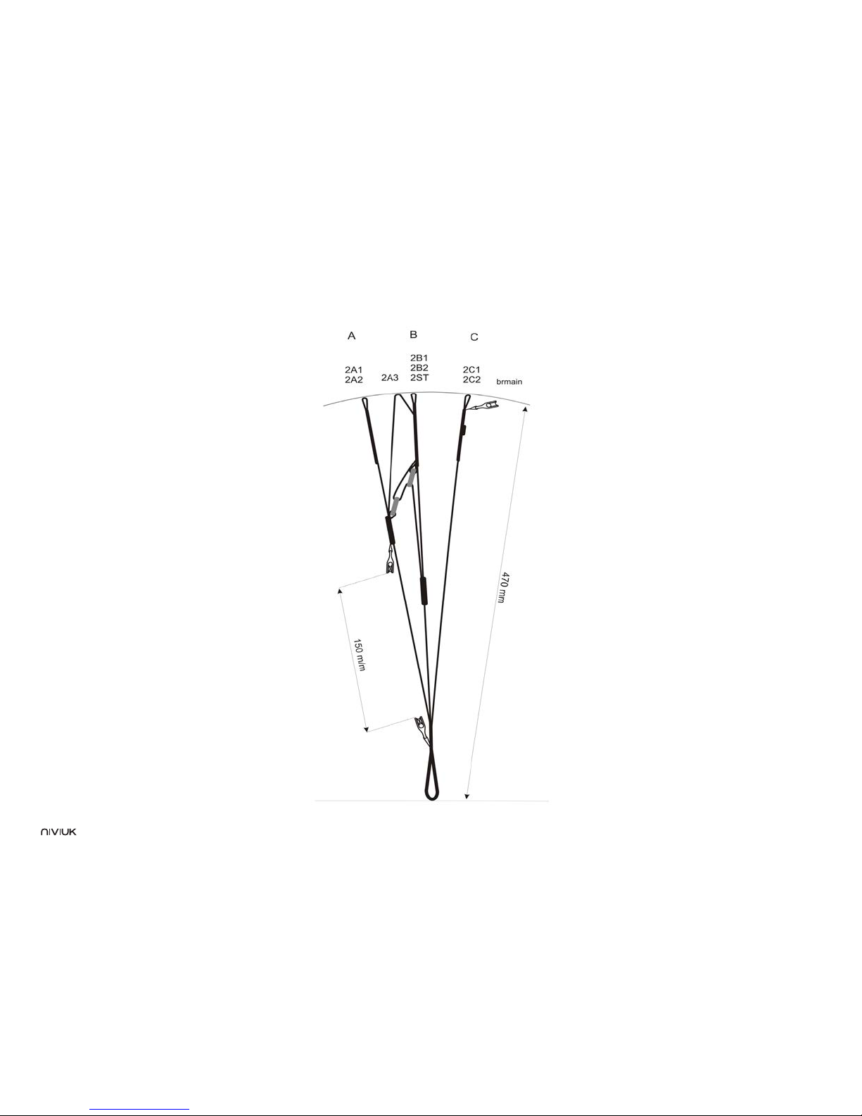
11.3 RISERS ARRANGEMENT
Page 17
17
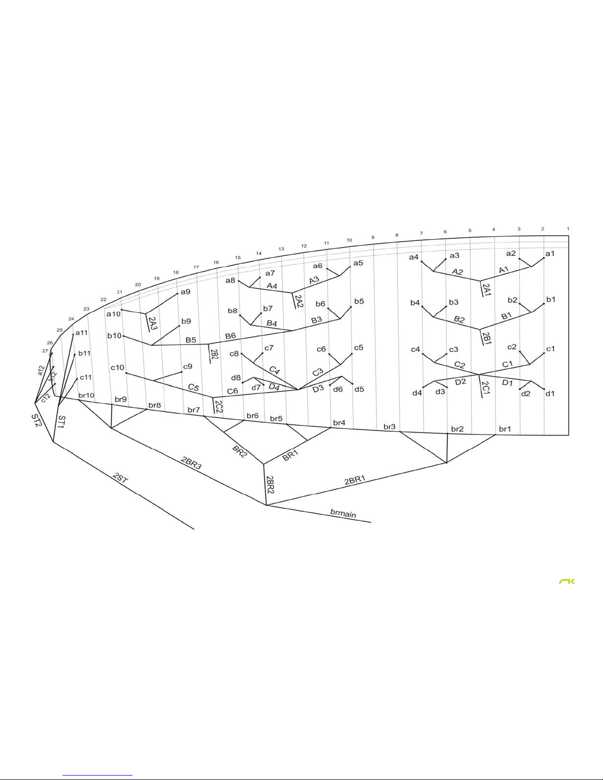
11.4 LINE PLAN
Page 18
18
11.6 LENGHTS HOOK 3 23
NIVIUK HOOK 3 23
LINES HEIGHT M/M
A B C D BR
1 6313 6202 6301 6410 7047
2 6249 6140 6212 6324 6717
3 6209 6103 6165 6264 6550
4 6229 6125 6212 6306 6431
5 6192 6148 6249 6338 6299
6 6151 6093 6170 6256 6259
7 6099 6010 6063 6140 6325
8 6116 6021 6090 6159 6157
9 5935 5922 6001 6082
10 5789 5890 6024 6072
11 5561 5550 5654
12 5453 5460 5520
RISERS LENGHT M/M
A B C D
470 470 470 STANDARD
320 370 470 ACCELERATED
11.5 LENGHTS HOOK 3 21
NIVIUK HOOK 3 21
LINES HEIGHT M/M
A B C D BR
1 6014 5909 6003 6103 6716
2 5954 5849 5917 6021 6400
3 5914 5812 5872 5971 6239
4 5933 5832 5916 6011 6124
5 5895 5853 5939 6024 5998
6 5856 5801 5863 5945 5958
7 5806 5720 5761 5834 6021
8 5821 5731 5786 5853 5830
9 5648 5636 5701 5758
10 5508 5604 5723 5748
11 5292 5281 5380
12 5189 5195 5253
RISERS LENGHT M/M
A B C D
470 470 470 STANDARD
340 375 470 ACCELERATED
Page 19

19
11.7 LENGHTS HOOK 3 25
NIVIUK HOOK 3 25
LINES HEIGHT M/M
A B C D BR
1 6602 6488 6591 6700 7343
2 6537 6424 6498 6611 7000
3 6497 6386 6451 6560 6826
4 6519 6410 6500 6604 6703
5 6480 6434 6527 6621 6567
6 6437 6377 6446 6535 6525
7 6384 6291 6335 6418 6595
8 6402 6302 6363 6436 6396
9 6213 6200 6271 6319
10 6061 6167 6296 6309
11 5825 5812 5920
12 5712 5719 5781
RISERS LENGHT M/M
A B C D
470 470 470 470 STANDARD
360 380 420 470 ACELERATED
11.8 LENGHTS HOOK 3 27
NIVIUK HOOK 3 27
LINES HEIGHT M/M
A B C D BR
1 6881 6762 6870 6983 7667
2 6814 6696 6774 6891 7311
3 6774 6658 6726 6834 7131
4 6797 6683 6778 6880 7005
5 6756 6695 6806 6903 6863
6 6712 6636 6722 6814 6820
7 6659 6546 6607 6690 6894
8 6677 6558 6636 6712 6689
9 6482 6461 6541 6610
10 6324 6426 6567 6600
11 6077 6064 6177
12 5960 5967 6032
RISERS LENGHT M/M
A B C D
470 470 470 STANDARD
320 370 470 ACCELERATED
Page 20

20
11.9 LENGHTS HOOK 3 29
NIVIUK HOOK 3 29
LINES HEIGHT M/M
A B C D BR
1 7150 7027 7138 7256 7970
2 7081 6959 7039 7161 7601
3 7040 6921 6991 7108 7415
4 7065 6947 7045 7156 7285
5 7023 6975 7075 7176 7139
6 6978 6914 6988 7084 7095
7 6923 6822 6869 6955 7172
8 6942 6834 6900 6978 6967
9 6740 6725 6801 6885
10 6576 6690 6829 6875
11 6321 6307 6424
12 6199 6207 6274
RISERS LENGHT M/M
A B C D
470 470 470 STANDARD
320 370 470 ACCELERATED
Page 21
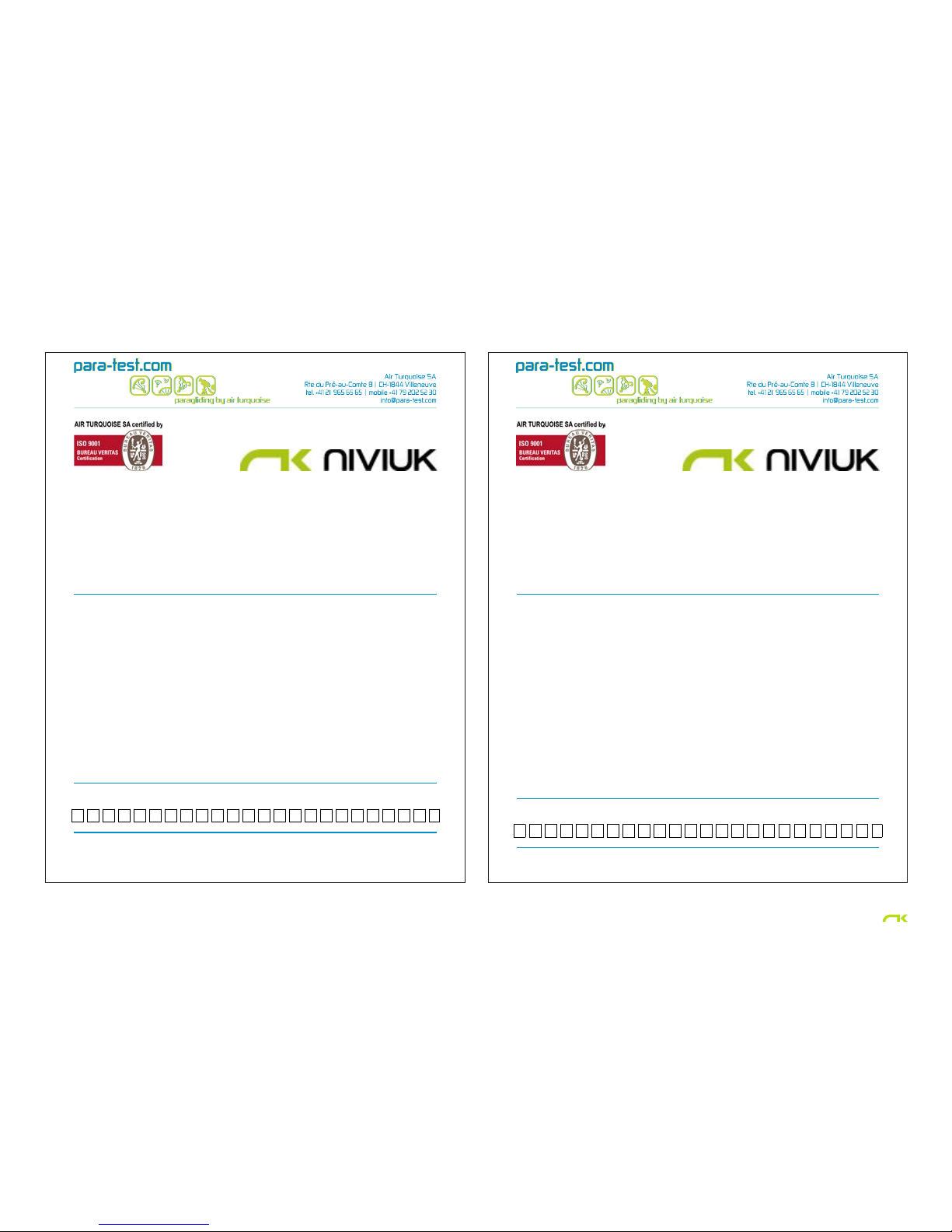
Class: B
In accordance with EN standards 926-2:2005 & 926-1:2006: PG_0721.2013
Date of issue (DMY): 11. 06. 2013
Manufacturer: Niviuk Gliders / Air Games S.L.
Model: Hook 3 21
Serial number:
Configuration during flight tests
Paraglider Accessories
Maximum weight in flight (kg) 70 Range of speed system (cm) 13
Minimum weight in flight (kg) 59 Speed range using brakes (km/h) 14
Glider's weight (kg) 4.5 Range of trimmers (cm) 0
Number of risers 3 Total speed range with accessories (km/h) 25
Projected area (m2) 17.85
Harness used for testing (max weight) Inspections (whichever happens first)
Harness type ABS every 24 months or every 100 flying hours
Harness brand Sup'Air Warning! Before use refer to user's manual
Harness model AltiplumeSPerson or company having presented the
glider for testing: None
Harness to risers distance (cm) 49
Distance between risers (cm) 42
1A2A3A4A5A6A7A8A9B10A11A12A13A14B15A16A17A18A19A20B21B22A23A24
0
Class: B
In accordance with EN standards 926-2:2005 & 926-1:2006: PG_0668.2013
Date of issue (DMY): 06. 02. 2013
Manufacturer: Niviuk Gliders / Air Games S.L.
Model: Hook 3 23
Serial number:
Configuration during flight tests
Paraglider Accessories
Maximum weight in flight (kg) 85 Range of speed system (cm) 15
Minimum weight in flight (kg) 65 Speed range using brakes (km/h) 14
Glider's weight (kg) 4.7 Range of trimmers (cm) 0
Number of risers 3 Total speed range with accessories (km/h) 25
Projected area (m2) 19.55
Harness used for testing (max weight) Inspections (whichever happens first)
Harness type ABS
Standard
every 24 months or every 100 flying hours
Harness brand Niviuk
Gliders
Warning! Before use refer to user's manual
Harness model Konvers M Person or company having presented the
glider for testing: none
Harness to risers distance (cm) 49
Distance between risers (cm) 46
1A2A3A4A5A6A7A8A9B10A11A12A13A14B15A16A17A18A19A20A21A22A23A24
0
21
11.10 CERTIFICATION SPECIMEN TEST
Page 22
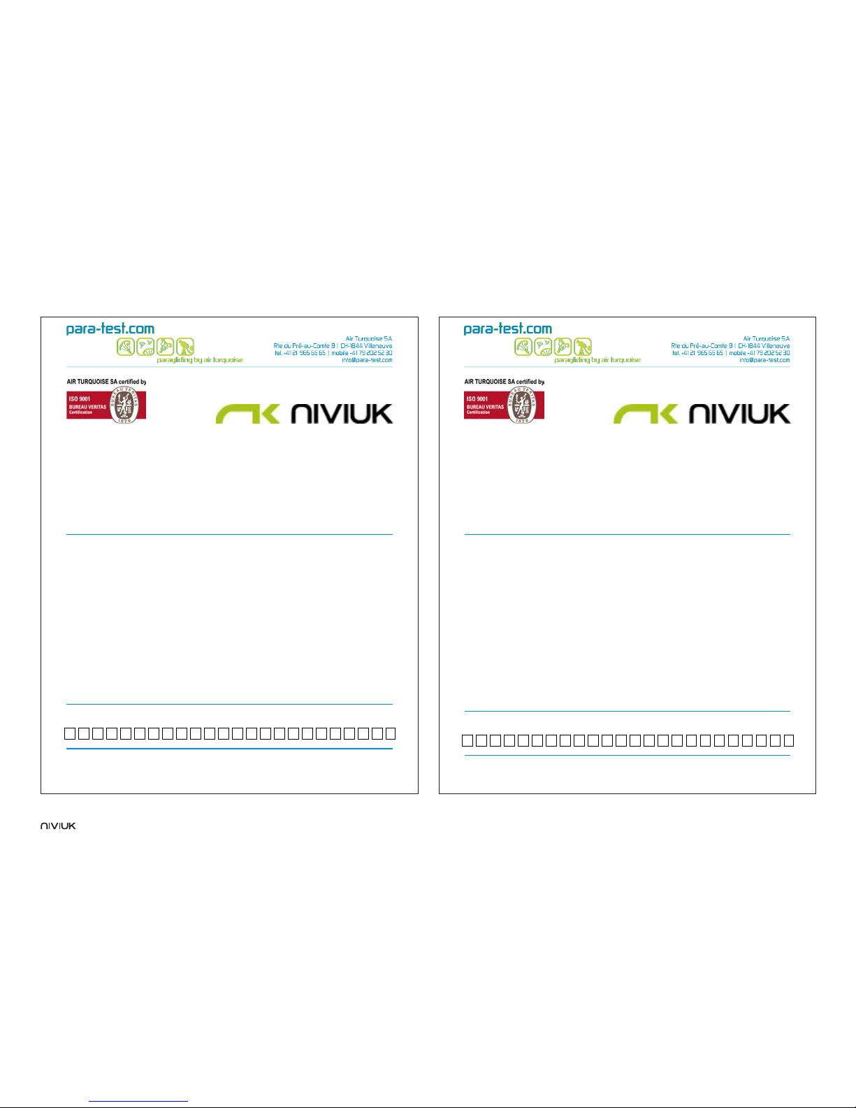
Class: B
In accordance with EN standards 926-2:2005 & 926-1:2006: PG_0669.2013
Date of issue (DMY): 21. 02. 2013
Manufacturer: Niviuk Gliders / Air Games S.L.
Model: Hook 3 27
Serial number:
Configuration during flight tests
Paraglider Accessories
Maximum weight in flight (kg) 115 Range of speed system (cm) 15
Minimum weight in flight (kg) 95 Speed range using brakes (km/h) 15
Glider's weight (kg) 5.3 Range of trimmers (cm) 0
Number of risers 3 Total speed range with accessories (km/h) 26
Projected area (m2) 22.95
Harness used for testing (max weight) Inspections (whichever happens first)
Harness type ABS every 24 months or every 100 flying hours
Harness brand Niviuk
Gliders
Warning! Before use refer to user's manual
Harness model Hamak L Person or company having presented the
glider for testing: None
Harness to risers distance (cm) 49
Distance between risers (cm) 46
1A2A3A4A5A6A7A8A9B10A11A12A13A14B15A16A17A18A19A20A21A22A23A24
0
Class: B
In accordance with EN standards 926-2:2005 & 926-1:2006: PG_0630.2012
Date of issue (DMY): 09. 01. 2013
Manufacturer: Niviuk Gliders / Air Games S.L.
Model: Hook 3 25
Serial number:
Configuration during flight tests
Paraglider Accessories
Maximum weight in flight (kg) 100 Range of speed system (cm) 15
Minimum weight in flight (kg) 80 Speed range using brakes (km/h) 15
Glider's weight (kg) 4.9 Range of trimmers (cm) 0
Number of risers 3 Total speed range with accessories (km/h) 27
Projected area (m2) 21.25
Harness used for testing (max weight) Inspections (whichever happens first)
Harness type ABS every 24 months or every 100 flying hours
Harness brand Sup'Air Warning! Before use refer to user's manual
Harness model AltiplumeMPerson or company having presented the
glider for testing: None
Harness to risers distance (cm) 49
Distance between risers (cm) 46
1A2A3A4A5A6A7A8A9B10B11A12A13A14B15A16A17A18A19A20A21A22A23A24
0
22
Page 23
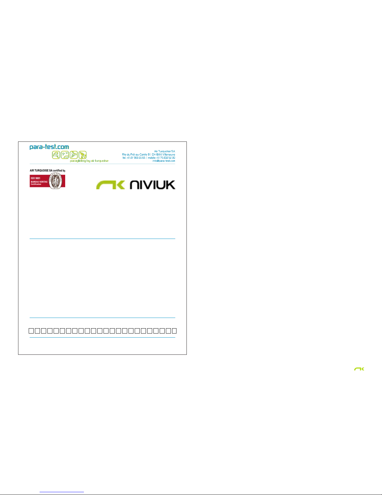
Class: B
In accordance with EN standards 926-2:2005 & 926-1:2006: PG_0698.2013
Date of issue (DMY): 17. 05. 2013
Manufacturer: Niviuk Gliders / Air Games S.L.
Model: Hook 3 29
Serial number:
Configuration during flight tests
Paraglider Accessories
Maximum weight in flight (kg) 130 Range of speed system (cm) 15
Minimum weight in flight (kg) 110 Speed range using brakes (km/h) 14
Glider's weight (kg) 5.8 Range of trimmers (cm) 0
Number of risers 3 Total speed range with accessories (km/h) 24
Projected area (m2) 24.65
Harness used for testing (max weight) Inspections (whichever happens first)
Harness type ABS every 24 months or every 100 flying hours
Harness brand Niviuk
Gliders
Warning! Before use refer to user's manual
Harness model Hamak M Person or company having presented the
glider for testing: None
Harness to risers distance (cm) 49
Distance between risers (cm) 46
1A2A3B4A5A6A7A8A9B10A11A12A13B14B15A16A17A18A19A20A21A22A23A24
0
23
Page 24

The importance of small details
niviuk.com
 Loading...