


User Manual
NR-70 Router
Prelimary version 2.8

Copyright Notice
© 2017 Niveo International BV
All rights reserved.
The information of this publication is protected by copyright. No part of this publication may be
reproduced, transmitted, transcribed, stored in a retrieval system, or translated into any language
without written permission from the copyright holders. The scope of delivery and other details are
Other trademarks and registered trademarks of products mentioned in this publication may be the
properties of their respective owners and are only used for identification purposes.

Table of Contents
About this Manual ........................................................................................................................... 1
0.1 Web UI Style .................................................................................................................. 1
0.2 Documents Conventions ................................................................................................ 1
0.2.1 Format ................................................................................................................... 1
0.2.2 Icons ...................................................................................................................... 1
0.3 Factory Default Settings ................................................................................................. 2
Chapter 1. Hardware Installation .................................................................................................. 3
1.1 Panel Description ........................................................................................................... 3
1.2 Installation Guideline ...................................................................................................... 4
1.3 Installation Requirements ............................................................................................... 5
1.4 Installation Procedure .................................................................................................... 5
1.5 Connecting the Device ................................................................................................... 6
Chapter 2. the Device................................................................................................................... 7
2.1 Configuring your computer ............................................................................................. 7
2.2 Logging to the Device .................................................................................................... 9
Chapter 3. Start Menu ................................................................................................................ 11
3.1 Setup Wizard ............................................................................................................... 11
3.1.1 Running the Setup Wizard ................................................................................... 11
3.1.2 Setup Wizard - WAN1 Settings ............................................................................ 12
3.2 Interface Status ............................................................................................................ 13
3.3 Interface Traffic ............................................................................................................ 13
3.4 Restart Device ............................................................................................................. 15
Chapter 4. Network Menu .......................................................................................................... 16
4.1 WAN ............................................................................................................................ 16
4.1.1 PPPoE Connection .............................................................................................. 16
4.1.2 Static IP Connection ............................................................................................ 18
4.1.3 DHCP Connection ............................................................................................... 19
4.1.4 Internet Connection List ....................................................................................... 19
4.1.5 Edit the Connection ............................................................................................. 20
4.1.6 Delete the Connection ................................ ......................................................... 21
4.1.7 Dial or Hang up a PPPoE connection ................................................................ .. 21
4.1.8 Renew or Release a DHCP Connection .............................................................. 22
4.2 Load Balancing ............................................................................................................ 22
4.2.1 Internet Connection Detection Mechanism .......................................................... 22
4.2.2 Global Settings .................................................................................................... 23
4.2.3 Load Balancing List ............................................................................................. 25

4.2.4 Detection and Bandwidth ..................................................................................... 26
4.2.5 Identity Binding .................................................................................................... 27
4.3 LAN .............................................................................................................................. 27
4.4 DHCP Server ............................................................................................................... 29
4.4.1 DHCP Server Settings ......................................................................................... 29
4.4.2 Static DHCP ........................................................................................................ 31
4.4.3 DHCP Auto Binding ............................................................................................. 32
4.4.4 DHCP Client List .................................................................................................. 33
4.4.5 Example of DHCP ............................................................................................... 34
4.5 DDNS........................................................................................................................... 35
4.5.1 DDNS Service provided by no-ip.com .................................................................. 35
4.5.2 DDNS Service provided by dyndns.org ................................................................ 36
4.5.3 DDNS Verification ................................................................................................ 37
4.6 UpnP ............................................................................................................................ 38
4.7 Number of WAN ........................................................................................................... 39
Chapter 5. Advanced Menu ................................................................................................ ........ 40
5.1 NAT&DMZ .................................................................................................................... 40
5.2 Static Route.................................................................................................................. 51
5.3 Policy Routing .............................................................................................................. 53
5.4 Anti-NetSniper .............................................................................................................. 56
5.5 Plug and Play ............................................................................................................... 56
5.6 Port Mirroring ............................................................................................................... 57
5.7 Syslog .......................................................................................................................... 58
5.8 Network Sharing Menu ................................................................................................. 59
5.9 Sharing Management ................................................................................................... 59
5.10 FTP Server ............................................................................................................... 60
5.11 Shared Account ........................................................................................................ 62
Chapter 6. User Management Menu .......................................................................................... 64
6.1 User Status .................................................................................................................. 64
6.2 IP/MAC binding ............................................................................................................ 66
6.3 PPPoE Server .............................................................................................................. 74
6.4 Web Authentication ...................................................................................................... 85
6.5 User Group .................................................................................................................. 89
Chapter 7. App Control Menu ..................................................................................................... 91
7.1 Schedule ...................................................................................................................... 91
7.2 Application Control ....................................................................................................... 92
7.3 QQ Whitelist ................................................................................................................. 98

7.4 MSN Whitelist .............................................................................................................. 99
7.5 TradeManager............................................................................................................ 100
7.6 Notification ................................................................................................................. 101
7.7 Application Audit ........................................................................................................ 104
7.8 Policy Database ......................................................................................................... 105
Chapter 8. QoS Menu .............................................................................................................. 107
8.1 Fixed Rate Limiting .................................................................................................... 107
8.2 Flexible Bandwidth ..................................................................................................... 108
8.3 P2P Rate Limit ........................................................................................................... 109
8.4 Session Limiting ......................................................................................................... 110
Chapter 9. Firewall Menu ......................................................................................................... 112
9.1 Attack Prevention ....................................................................................................... 112
9.2 Access Control ........................................................................................................... 114
9.3 Domain Filtering ......................................................................................................... 126
9.3.1 Domain Filtering Settings ................................................................................... 127
9.3.2 Domain Block Notification .................................................................................. 128
9.4 MAC Address Filtering ............................................................................................... 129
Chapter 10. VPN Menu ........................................................................................................... 132
10.1 Introduction to VPN Technologies ........................................................................... 132
10.2 PPTP ...................................................................................................................... 133
10.3 IPSec ...................................................................................................................... 144
Chapter 11. System Menu ...................................................................................................... 163
11.1 Administrator .......................................................................................................... 163
11.2 Language ............................................................................................................... 163
11.3 Time ....................................................................................................................... 164
11.4 Configuration .......................................................................................................... 165
11.5 Firmware Upgrade .................................................................................................. 166
11.6 Remote Management ............................................................................................. 167
11.7 Scheduled Task ...................................................................................................... 168
Chapter 12. Status Menu ........................................................................................................ 170
12.1 Interface Status ....................................................................................................... 170
12.2 System Information ................................................................................................. 170
12.3 System Log ............................................................................................................. 171
Appendix A FAQ .......................................................................................................................... 173
Appendix B Common IP Protocols .............................................................................................. 177
Appendix C Common Service Ports ............................................................................................ 178

Niveo Professional NR-70
About this Manual
Note:
For better use experience, it is strongly recommended to use Internet Explorer 8.0 or above, Google
Chrome and Firefox.
0.1 Web UI Style
The Device’s Web User Interface (Web UI) follows the web standards, as follows:
Radio Button: Allows you to choose from only one of a predefined set of options.
Check Box: Allows you to select one or more options.
Button: Allows you to click to perform an action.
Text Box: Allows you to enter text information.
:List Box: Allows you to select one or more items from a static multiple line text box.
:Drop-down List: Allows you to choose one item from a list. When a drop-down
list is inactive, it displays a single item. When activated, it drops down a list of items, from which you
may select one.
0.2 Documents Conventions
0.2.1.1 Format
Notes: You need pay attention to the notes content.
Parameters: Describe the meaning of parameter or button. If there have “*” before parameters,
it couldn’t be empty.
Bullets: List the parallel content.
Boldface font: Examples of information displayed on the screen.

Niveo Professional NR-70
0.3 Factory Default Settings
The factory default settings of interfaces are shown in the following table.
Parameter
Default Value
Description
User Name
admin
Both the User Name and
Password are case sensitive.
Password
admin
LAN IP Address
192.168.1.1/255.255.255.0
You can use this IP address to
access the Device through a
Web browser.
Table 0- 1 Factory Default Settings of Interface
}
Chapter 1. Hardware Installation
This chapter describes the physical characteristics of the Device, and explains how to
install them.
1.1 Panel Description
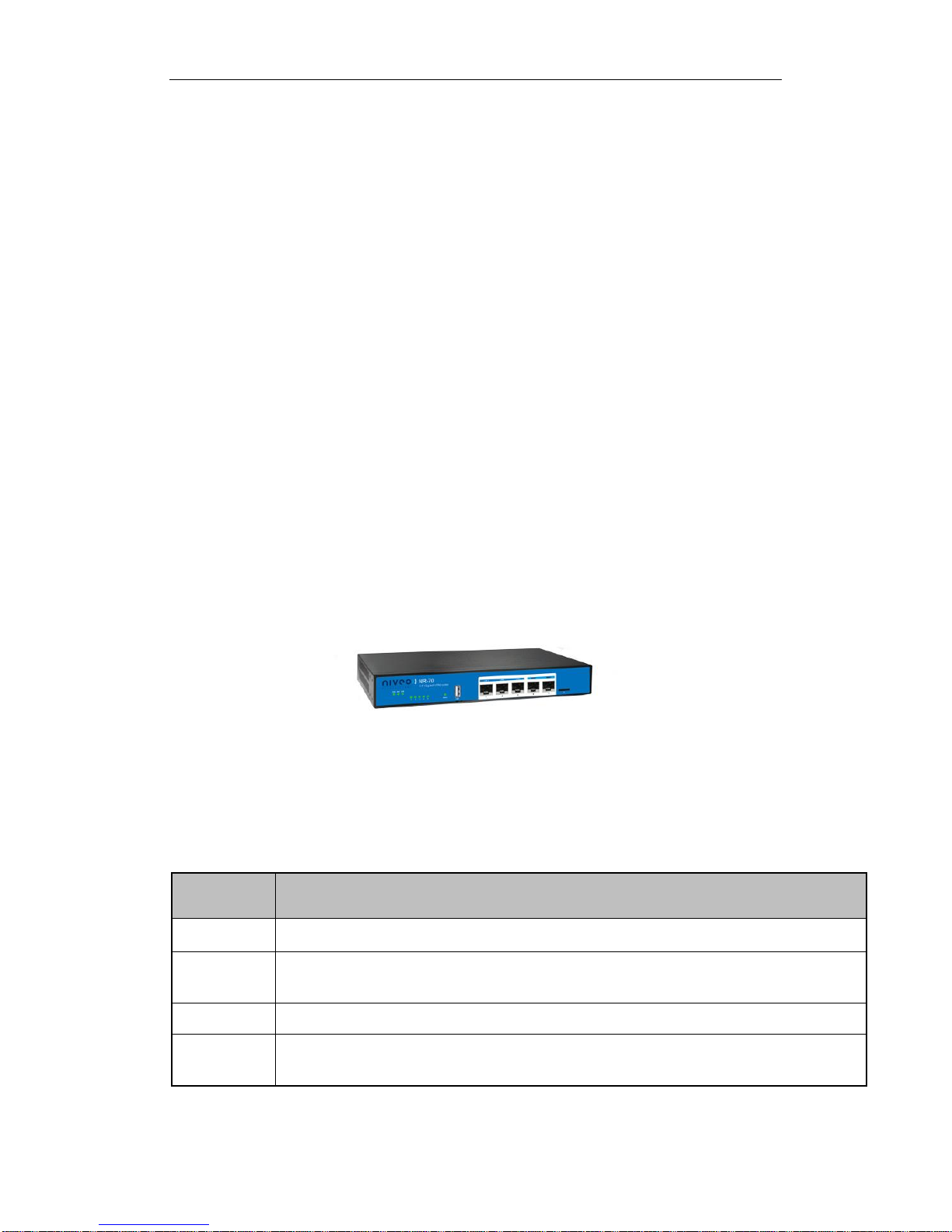
1) Front Panel
The LED indicators, the interface and the button are located on the front panel of the
Device please see the product.
Figure 1-1 Front Panel_NR70
LED
Description
PWR
The Power LED indicator is on when the Device is powered on.
SYS
The LED indicator blinks twice per second when the system is working properly,
and it will blink slower under heavy load.
USB
The LED indicator is on when the USB interface is connected properly.
1,2,3,4,5
The LAN LED indicator is on when Ethernet cable connection is normal, and it
blinks when the LAN port is sending or receiving data.
Table 1-1 LEDs Description

}
Interface
Description
LAN Port
These interfaces provide a LAN connection to network devices, such as PCs
or switches.
WAN Port
The WAN interface is connected to your Internet device, such as PCs or
switches. The number of WAN ports depends on the device model.
TF
Connect TF card for data sharing.
USB
Plug-in a USB storage for specific features.
Table 1-2 Ports Description
Button
Description
Reset
Reset current settings to the factory default settings. When the Device is
powered on, use a pin or paperclip to press and hold the Reset button for
more than 5 seconds, and then release the button. After that, the Device will
restart with the factory default settings.
Note: The reset operation will clear all the settings and preferences that you have configured.
You can also recover the Device 's factory configuration on the System > Configuration page.
Table 1-3 Ports Description
1.2 Installation Guideline
When determining where to place the Device, please observe these guidelines:
Make sure that your workbench or standard rack is level and stable.
Do not place heavy objects on the Device!
Make sure that there is proper heat dissipation and adequate ventilation
around the Device.

}
Position the Device out of direct sunlight and away from sources of heat and
ignition.
Please install the Device in a place far away from the High Power Radio or
Radar Station.
Keep the Device far away from water!
Please use the supplied power cord.
1.3 Installation Requirements
The following items are required for installation:
1) Broadband Internet connection
2) Tools and equipment
(1) Broadband modem (optional)
(2) PC with an Ethernet card and TCP/IP installed
(3) Network devices like hub, switch, wireless access point
(4) Network cables
(5) Screwdriver
(6) Power outlet
1.4 Installation Procedure
Follow these steps to install the Device on a flat surface such as a bench:
1) Make sure the Device is powered off.
2) Place the Device upside down on a sturdy, flat bench with a power outlet nearby.
Verify that the bench is well grounded.
3) Remove the adhesive backing from the supplied rubber feet. Attach the four
rubber feet to the round recessed areas on the bottom of the Device.
4) Turn the Device over to make it right side up on the bench.

}
1.5 Connecting the Device
Before you install the Device, please make sure your PC can connect to the Internet
through your broadband service successfully. If there is any problem, please contact
with your ISP for help.
After that, please install the Device according to the following steps. Don’t forget to
pull out the power plug and keep your hands dry.
1) Power off your PC(s), CableDSL modem, and the Device.
2) Connect the Cable/DSL modem to the Device’s WAN port.
3) Connect one end of an Ethernet cable to one of the LAN ports on the Device, and
the other end to a network port on a PC, hub, switch or wireless access point.
Repeat this step to connect more PCs or other network devices to the Device.
4) Connect the power cord to the power port of the Device. Then plug the other end
of the power cord to a grounded AC power outlet.
5) Power on your network devices, PCs, Switches, Hubs, and so on.

}
Chapter 2. the Device
This chapter describes how to configure TCP/IP settings on your computer, and how
to login to the Device. In addition, it briefly describes the layout of the Device’s Web
interface.
2.1 Configuring your computer
To configure the Device via Web UI, you need to properly configure TCP/IP settings
on the computer that you use to manage the Device. To do this, follow these steps:
Step 1 Connect the computer to a LAN port of the Device, or connect the computer
to the Device through wireless.
Step 2 Install TCP/IP protocol on your computer. If it is already installed, please
skip this step.
Step 3 Configure TCP/IP settings as Obtain an IP address automatically and
Obtain DNS server address automatically. More information about how
to configure TCP/IP, please refer to the chapter: Appendix A FAQ.
Step 4 Use the Ping command to verify network connectivity between the computer
and the Device. Open the command prompt on the computer, type ping
192.168.1.1, and then press Enter.
A successful ping will look like this:

}
An unsuccessful ping will look like this:
If the Ping command is successful, the connection between the computer and the
Device is working properly. If the Ping command fails, please do the following:
1) Check physical connection: Verify that the LAN LED on the Device and the LED
on your computer’s network card are lit.
2) Check TCP/IP settings: Verify that your computer is on the same subnet as the
Device’s LAN interface. E.g., if the Device’s LAN IP address is 192.168.1.1
(default), the computer’s IP address must be an unused IP address in the
192.168.1.0/24 subnet.
Pinging 192.168.1.1 with 32 bytes of data:
Request timed out.
Request timed out.
Request timed out.
Request timed out.
Ping statistics for 192.168.1.1:
Packets: Sent = 4, Received = 0, Lost = 4 (100% loss),
Pinging 192.168.1.1 with 32 bytes of data:
Reply from 192.168.1.1: bytes=32 time<1ms TTL=255
Reply from 192.168.1.1: bytes=32 time<1ms TTL=255
Reply from 192.168.1.1: bytes=32 time<1ms TTL=255
Reply from 192.168.1.1: bytes=32 time<1ms TTL=255
Ping statistics for 192.168.1.1:
Packets: Sent = 4, Received = 4, Lost = 0 (0% loss),
Approximate round trip times in milli-seconds:

}
2.2 Logging to the Device
No matter what operating system is installed on your computer, such as, MS Windows,
Macintosh, UNIX, or Linux, and so on, you can configure the Device through the Web
browser (e.g., Internet Explorer, Firefox).
Step 1: For local access of the Device’s web-based utility, launch your web browser,
and enter the Device’s default IP address: 192.168.1.1, in the URL filed. Then press
the Enter key.
Figure 2-1 Address Bar
Step 2: A login screen prompts you for your User name and Password. Enter admin
(case sensitive) in the User name field, and enter admin in the Password field. Then
click Log In.
Figure 2-2 Login Screen
Step 3: After log in the Device, the first screen that appears is the Homepage.

}
Figure 2-3 Homepage
Home page Description:
(1) Niveo Logo: Click to go to the home page on the UTT website.
(2) Model, Hardware Version and Software Version: Displays the model number,
software version and firmware version of the Device.
(3) Quick Link Icons: Provide quick links to the corresponding pages on the UTT
website.
Product: Click to go to the products page on the UTT website to find more
products.
Forum: Click to go to the forum home page on the UTT website to participate
in product discussions.
Feedback: Click to send us your feedback by email.
1) On left side there is two-level main menu bar. You can click a first level menu item
to reveal its submenu items, click again to hide them.
2) The main operating page is located on the centre of the page, in which you can
configure various functions, view the related configuration information and status
information, etc.
3) The bottom of the page there is copyright information.

}
Chapter 3. Start Menu
The Start menu is located in the upper left of the WEB interface, which provides you
four commonly used functions: Setup Wizard, Interface Status, Interface Traffic,
and Restart Device. In this chapter, you can configure the basic parameters to
access to internet, view each physical interface’s detail information and restart the
Device.
3.1 Setup Wizard
This section describes the Start > Setup Wizard page. The Setup Wizard will guide
you to configure the basic parameters to quickly connect the Device to the Internet.
Even unfamiliar with the product, you still can follow the instructions to complete the
setup easily.
The first page appears is Setup Wizard immediately after your first login.
Figure 3-1 Running the Setup Wizard
Do Not Automatically Launch Setup Wizard Again: If selected, the system
don’t automatically launch the Setup Wizard the next time you login to the
Device, instead directly open the System Information page(see Figure 3-2).
Else, the system will still launch the Setup Wizard automatically.
Exit Wizard: Click to exit the Setup Wizard and go to the System Information
page (see Figure 3-2). The changes made in the Setup Wizard will be discarded.

}
Next: Click to enter into the next page of the Setup Wizard.
Figure 3-2 System Information
There are three connection types you can configure for WAN Internet connection:
PPPoE, Static IP and DHCP. For the detail information, you can refer to the chapter:
4.1 WAN.
Figure 3-3 Setup Wizard_WAN1 Settings
Figure 3-4 Setup Wizard_2.4G Wireless Settings
the optimal channel bandwidth.

}
3.2 Interface Status
On the Start > Interface Status page, you can view the current status of all physical
interface, including the type of interface, connection type, status, IP address, duration
and so on.
Figure 3-5 Interface Status
3.3 Interface Traffic
The interface rate chart dynamically displays the real-time RX/TX rate, average
RX/TX rate, maximum RX/TX rate and total RX/TX traffic of each physical interface. If
you want to view the rate chart of an interface, click the corresponding interface name
hyperlink.
In the interface rate chart, the abscissa (x-axis) shows the time axis, and the ordinate
(y-axis) shows the real-time RX/TX rate axis. Furthermore, you can adjust some
parameters of the chart if needed, such as the time interval during which the real-time
rates are calculated and displayed, and the displayed colors.
Note: The rate chart can only show the rate and traffic information in the last ten
minutes. Each time you launch this page, the rate chart refreshes.

}
Figure 3-6 Interface Status
RX: Displays the real-time RX rate of the physical interface, which refreshes
every two seconds. For the LAN interface, RX means uploading; for the WAN
interface, it means downloading.
TX: Displays the real-time TX rate of the physical interface, which refreshes every
two seconds. For the LAN interface, TX means downloading; for the WAN
interface, it means uploading.
Avg: Displays the average RX or TX rate of the physical interface since last
opened the current page.
Peak: Displays the maximum RX or TX rate of the physical interface since last
opened the current page.
Total: Displays the total RX or TX traffic of the physical interface since last
opened the current page.
LAN/WANx: Click the interface name hyperlink to view the rate chart of the
selected interface. Therein, x (value: 1, 2, 3, 4) indicates the corresponding WAN
interface, and the number of WAN interfaces depends on the specific product
model. For example, click the WAN1 hyperlink to view the rate chart of the WAN1
interface.
Note:
If the SVG Viewer isn’t installed on your PC, the rate chart cannot be displayed
properly. To view the rate chart, click the (Please install svgviewer if the page
cannot display properly.) hyperlink to download and install the SVG Viewer.

}
3.4 Restart Device
On the Start > Restart Device page, you can restart the Device. Clicking the Restart
button, the system will pop up a dialog. Then you can click the OK button to restart the
Device, or click the Cancel button to cancel the operation.
Figure 3-7 Restart Device
Note: Because restarting the Device will disconnect all the sessions, please do it
with caution.

}
Chapter 4. Network Menu
4.1 WAN
This section describes Network > WAN page, you can setup the way access to
Internet. There are three connection types: PPPoE, Static IP and DHCP (Obtain an IP
automatically). Depending on which connection type you select, you will see various
settings. We will describe the settings for each connection type respectively.
Figure 4-1 Select Connection Type
The Point-to-Point Protocol over Ethernet (PPPoE) is a network protocol for
encapsulating PPP frames inside Ethernet frames. Most DSL-based Internet
Service Providers (ISPs) use PPPoE to establish Internet connections for
end-users. If you use a DSL line, check with your ISP to see if they use PPPoE,
and then select PPPoE.

}
Figure 4-2 PPPoE Connection Setup
ISP Policy: Select the ISP Policy (i.e., route policy database) for each Internet
connection. Thus all traffic destined to an ISP’s servers will be forwarded through
that ISP’s connection.
User Name and Password: Enter the PPPoE login user name and password
provided by your ISP.
PPP Authentication: Specify the PPP authentication mode, available options:
NONE, PAP, CHAP and Either.
None: If selected, no protocol will be used.
PAP: If selected, PAP (Password Authentication Protocol) protocol will be
used for PPP authentication.
CHAP: If selected, CHAP (Challenge Handshake Authentication Protocol)
protocol will be used for PPP authentication.
Either: If selected, the Device will automatically negotiate with the peer
device to use PAP or CHAP protocol.
Dial Type: Select the type of dial connection, available options are Always On,
On Demand and Manual.
Always On: If selected, the Device will establish a PPPoE session when
starting up and automatically re-establish the PPPoE session once
disconnected.

}
On Demand: If selected, the Device will establish a PPPoE session only
when there are packets requesting to access the Internet (i.e., when a
program on your computer attempts to access the Internet).
Manual: If selected, you can dial or hang up a PPPoE session manually.
Dial Mode: If the PPPoE connection isn’t established successfully even using
correct user name and password, you may try to use other modes.
Idle Timeout: Specify the during time the Device keeps the Internet connection
active after no traffic. Which means not terminate Internet connection when the
value is zero.
MTU: When dialing, the Device will automatically negotiate MTU (maximum
transmission unit) with the peer device. Please leave the default value of 1480
bytes, unless you have a special application.
Advanced Options: Click to configure advanced parameters. In most case, you
need not configure them.
Some infrastructure situations have to use static address, such as finding the Domain
Name System (DNS) host where it is, the Device will translate domain names to IP
addresses. Static addresses are convenient, but not absolutely necessary, to locate
servers inside an enterprise.
If you are required to use a permanent IP address, select Static IP.
Figure 4-3 Static IP Connection Setup

}
ISP Policy: Select the ISP Policy (i.e., route policy database) for each Internet
connection. Thus all traffic destined to an ISP’s servers will be forwarded through
that ISP’s connection.
IP Address: Enter the IP address for the Device’s WAN interface, which is
provided by your ISP.
Subnet Mask: Enter the subnet mask for the Device’s WAN interface, which is
provided by your ISP.
Gateway IP: Enter the IP address for the default gateway, which is provided by
your ISP.
Primary DNS Server: Enter the IP address of your ISP’s primary DNS server.
Secondary DNS Server: Enter the IP address of your ISP’s secondary DNS
server if it is available.
The Dynamic Host Configuration Protocol (DHCP) is a standardized network protocol
used on IP networks for dynamically distributing network configuration parameters,
such as IP addresses for interfaces and services. With DHCP, computers request IP
addresses and networking parameters automatically from a DHCP server, reducing
the need for a network administrator or a user to configure these settings manually.
If your ISP automatically assigns an IP address, select DHCP. Most cable modem
subscribers use this connection type.
Figure 4-4 DHCP Connection Setup
When you have configured the Internet connection, you can view its status in the

}
Internet Connection List. Click Refresh button to view current status of the
connection.
Figure 4-5 Internet Connection List
Interface: Displays the name of the physical interface to which the connection is
bound.
Connection Type: Displays the type of the Internet connection.
Status: Displays the current status of the Internet connection. If the connection is
successful, it displays Connected, else it displays Disconnected. When the status
is connected on PPPoE mode, it will also display the elapsed time (day: hour:
minute: second) since connected. And when the status is connected on DHCP
mode, it will also display the time left before the lease expires (day: hour: minute:
second) for current IP address, which is assigned by your ISP’s DHCP server.
IP Address, Subnet Mask and Gateway IP: When the connection type is
PPPoE or DHCP, it displays the IP Address, Subnet Mask and Gateway IP
provided by ISP. When the connection type is Static IP, it displays the IP
Address, Subnet Mask and Gateway IP you set.
Rx Rate(bps): Displays the current download rate of the connection between the
refresh interval.
Tx Rate(bps): Displays the current upload rate of the connection between the
refresh interval.
If you want to edit the connection, do the following:
Step 1 In the Internet Connection List, click the WAN interface hyperlink, the
related information will be displayed in the setup fields.

}
Step 2 Modify the connection settings.
Step 3 Click the Save button to save the settings.
If you want to delete the connection, do the following:
Step 1 In the Internet Connection List, click the related WAN hyperlink, the
related information will be displayed in the setup fields.
Step 2 Click the Delete button below the Internet Connection List.
Step 3 In the pop-up window, click the OK button to delete the connection.
Note: The default WAN1 connection can’t be deleted but edited.
If the connection type is PPPoE, when you click the WAN1 hyperlink, the Connect,
Disconnect and Refresh buttons will be shown on the Internet Connection List.
Note:
1) If you have chosen Manual as Dial Type for PPPoE connection, you need click
the Connect button to dial-up the Internet connection, and click the Disconnect
button to hang it up.
2) Click the Refresh button to view current status of the connection.
Figure 4-6 Internet Connection List_PPPoE Connection
}
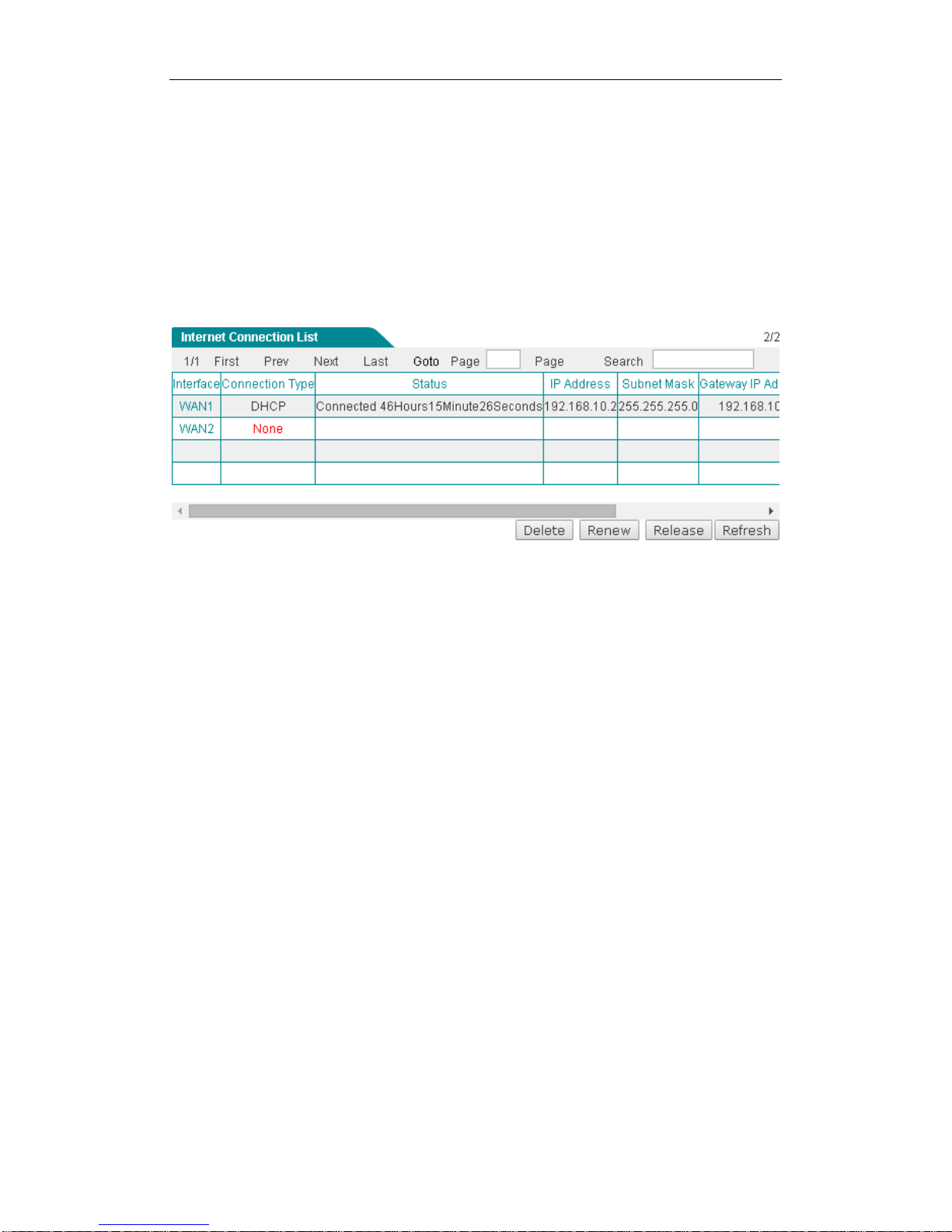
If the connection type is DHCP, when you click the WAN1 hyperlink, the Renew,
Release and Refresh buttons will be shown on the Internet Connection List.
Click the Renew button to re-acquire an IP address from the ISP’s DHCP server.
Click the Release button to release the IP address obtained from the ISP’s DHCP
server. Click the Refresh button to view current status of the connection.
Figure 4-7 Internet Connection List - DHCP Connection
4.2 Load Balancing
This section describes the Network > Load Balancing page. When using multiple
Internet connections, you can configure load balancing related parameters, such as,
load balancing mode, detection interval, retry times, and ID binding, and so on.
When using multiple Internet connections, the Device should has the ability to
real-time monitor each Internet connection to ensure the network will not be
interrupted even a connection is faulty. To this end, we design flexible automatic
detection mechanism on the Device, and provide multiple detection methods to meet
the actual requirements.
For the sake of convenience, we firstly introduce several parameters.
● Detection Target IP: The IP address of a target device. The Device will monitor
an Internet connection by sending the detection packets to the specified target IP
address.
● Detection Interval: The time interval at which the Device periodically sends
detection packets, one packet at a time. Especially, if you don’t want to monitor an

}
Internet connection, please set it as 0.
● Retry Times: The number of retries per detection period.
For a normal Internet connection and a faulty Internet connection, the detection
mechanisms are different.
For a faulty normal Internet connection, the detection mechanism is as follows: The
Device periodically sends a detection packet at the specified time interval to the target
IP address. Once no response packet received during a detection period, the Device
will consider that the connection is faulty and shield it immediately. For example, by
default, if the Device has sent three detection packets but not received any response
packet during a detection period, it will consider that the connection is faulty.
For a normal Internet connection, the detection mechanism is as follows: Similarly, the
Device also periodically sends a detection packet at the specified time interval to the
target IP address. Once more than half of the response packets received during a
detection period, the Device will consider that the connection is back to normal and
enable it immediately. For example, by default, if the Device has sent three detection
packets and received two packets during a detection period, it will consider that the
connection is back to normal.
Note: If you don’t want to monitor an Internet connection, please set the value of
Detection Interval as 0.
The Device provides two connection groups: primary connection group and backup
connection group. An Internet connection belonging to the primary connection group
is a primary connection, while an Internet connections belonging to the backup
connection group is a backup connection. By default, all the Internet connections are
primary connections. It allows you to divide one or more connections into the backup
connection group.
The Device provides two load balancing modes: Full Load Balancing and Partial
Load Balancing.
If you choose to use Full Load Balancing, all the Internet connections are used as
primary connections. The operation principle is as follows:
1) If all the Internet connections are normal, the LAN users will use these
connections to access the Internet.
2) If an Internet connection is faulty, the Device will shield it immediately, and the
traffic through the faulty connection will be distributed to other normal connections
automatically.

}
3) Once the faulty connection is back to normal, the Device will enable it immediately,
and the traffic will be redistributed automatically.
If you choose to use Partial Load Balancing, some Internet connections are used as
primary connections, and others are used as backup connections. The operation
principle is as follows:
1) As long as one or more primary connections are normal, the LAN users will use
the primary connection(s) to access the Internet. In this case, if there is more than
one primary connection, the Device will control and balance the traffic among
these connections.
2) If all the primary connections are faulty, it will automatically switch to the backup
connection(s) to let the LAN users use them to access the Internet. In this case, if
there is more than one backup connection, the Device will control and balance
the traffic among these connections.
3) Once one or more faulty primary connections are back to normal, it will
automatically switch back to the primary connection(s).
Note: During connections switching, some user applications (such as some
online games) may be interrupted unexpectedly due to the nature of TCP
connection. UTT Technologies Co., Ltd. will not bear all the losses and legal
proceedings caused by it.
4.2.2.1 Full Load Balancing
Select the Full Load Balancing checkbox and click the Save button to save the
settings.
Figure 4-8 Full Load Balacing
4.2.2.2 Partial Load Balancing
Select the Partial Load Balancing checkbox and then set primary connection and
backup connection, lastly click the Save button to save the settings.
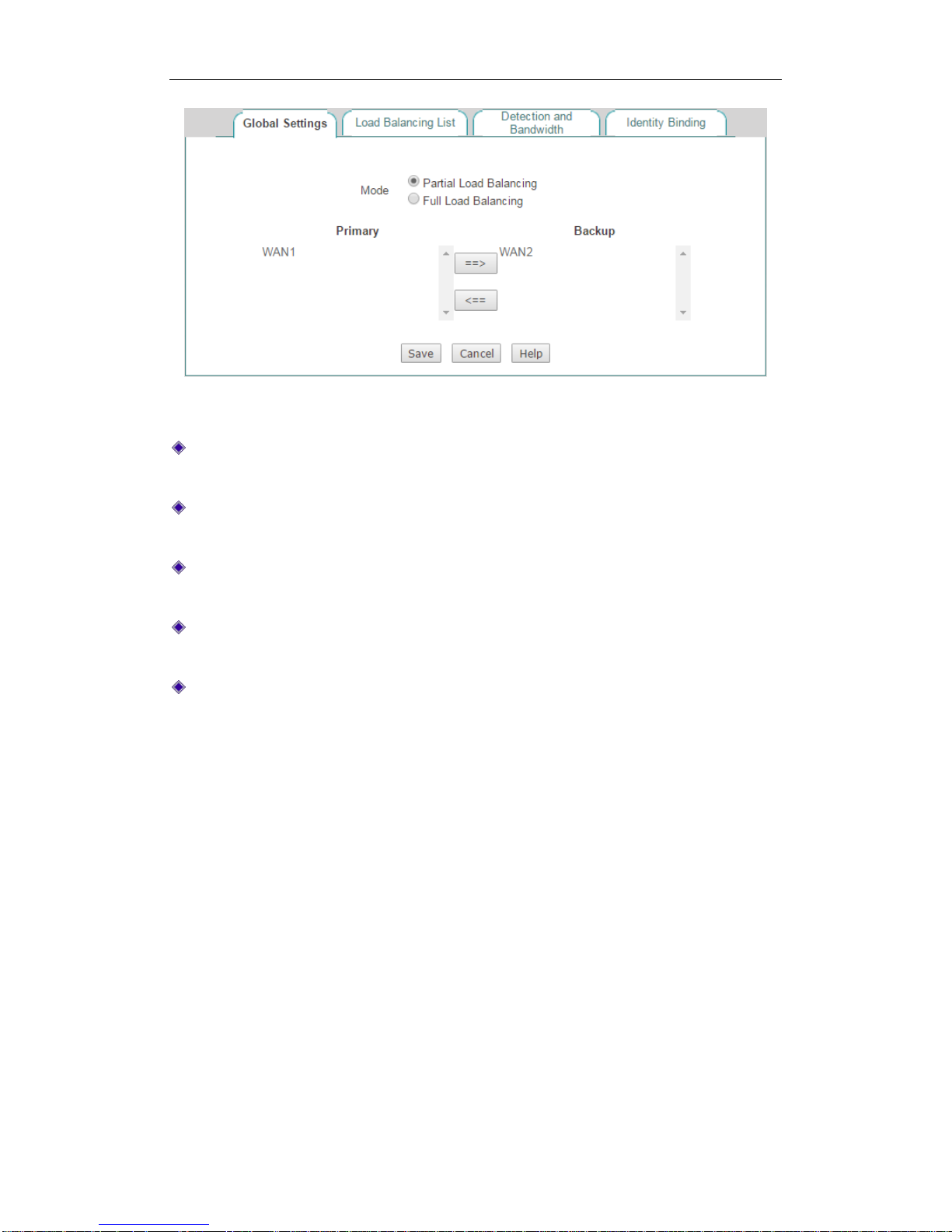
}
Figure 4-9 Partial Load Balancing
Mode: Specify the mode of load balancing. Here please select Partial Load
Balancing.
Primary: Specify the primary connection group. An Internet connection in the
Primary list box is a primary connection.
Backup: Specify the backup connection group. An Internet connection in the
Backup list box is a backup connection.
==>: Select one or more Internet connections in the Primary list box, and then
click ==> to move the selected connection(s) to the Backup list box.
<==: Select one or more Internet connections in the Backup list box, and then
click <== to move the selected connection(s) to the Primary list box.
When you have configured load balancing parameters for one or more Internet
connections, you can view the related configuration and status information in the
Load Balancing List.
If you want to modify the detection related parameters, click its Edit hyperlink, the
related information will be displayed in the Detection and Bandwidth page. Then
configure or modify it, and click the Save button.

}
Figure 4-10 Load Balancing List
In the Network > Load Balancing > Detection and Bandwidth page, you can
configure the connection detection related parameters for each Internet connection
respectively.
Figure 4-11 Detection and Bandwidth Settings
Interface: Select the physical interface you want to set load balancing.
Detection Interval: Specify the time interval at which the Device periodically
sends detection packets, one packet at a time. The value should be between 1
and 60 seconds, or 0. 0 means that connection detection is disabled on the
selected Internet connection.
Retry Times: Specify the number of retries per detection period.

}
Detection Target: The IP address of a detection target device. The Device will
monitor an Internet connection by sending the detection packets to the detection
target IP address. If you select Gateway IP Address from the drop-down list, the
Device will send the detection packets to the selected Internet connection’s
default gateway; If you select Other IP Address from the drop-down list, you
need enter an appropriate public IP address in the associated text box, then the
Device will send the detection packet to this IP address.
Bandwidth: Specify the bandwidth of this interface provided by ISP.
When using multiple Internet connections, the same application will be assigned to
the different connections, thus some applications (such as online banking, QQ, etc.)
cannot be used normally due to the identity change. We provide ID binding feature to
solve this problem: After you enable Identity Binding, the Device will assign the same
application to the same Internet connection. For example, when a LAN user logs in to
an online banking system, if the first session is assigned to the WAN2 Internet
connection, henceforth all the subsequent NAT sessions of the online banking
application will be assigned to the WAN2 connection until the user logs out.
Figure 4-12 Identity Binding
Enable ID Binding: If selected, you will enable ID binding feature for some
applications such as online banking, QQ, etc.
4.3 LAN
This section describes Network > LAN page. You can set up to four IP addresses for
the LAN interface. With the IP address of LAN interface, you can login to the Device. If
the IP address has been changed, you need to re-login to the Device using the new
address.

}
Figure 4-13 LAN Settings
IP Address: Specify the IP address of the LAN interface. The default value is
192.168.1.1.
Subnet Mask: Specify the subnet mask that defines the range of the LAN. The
default value is 255.255.255.0.
MAC Address: The MAC address of the LAN interface. We recommend that you
do not change the default value unless absolutely necessary.
Interface Mode: Specify the speed and duplex mode of the LAN interface. The
Device supports five or six modes (Note that only the gigabit LAN interface
supports 1000M-HD), which include Auto (Auto-negotiation), 10M-HD (10M
Half-Duplex), 10M-FD (10M Full-Duplex), 100M-HD (100M Half-Duplex),
100M-FD (100M Full-Duplex), and 1000M-FD (1000M Full-Duplex). In most
cases, please leave the default value. If a compatibility problem occurred, or the
network device connected to the LAN interface doesn’t support auto-negotiation
function, you may modify it as required.
Note:
1) You can assign two IP addresses to the Device’s LAN interface to connect two
subnets. The hosts on the two subnets can communicate with each other.
2) If you have changed the LAN IP address and saved the change, you should use
the new IP address to re-login to the Device. And the default gateway of each
LAN host should be changed to this new IP address, thus the LAN hosts can
access the Device and Internet.

}
4.4 DHCP Server
The Dynamic Host Configuration Protocol (DHCP) provides a framework for passing
configuration information to hosts on a TCP/IP network. DHCP allows a host to be
configured automatically, eliminating the need for intervention by a network
administrator. The Device can act as a DHCP server to assign network addresses and
deliver other TCP/IP configuration parameters (such as gateway IP address, DNS
server IP address, etc.) to the LAN hosts.
The DHCP server assigns an IP address to a requesting client from a DHCP address
pool, which also can be configured to provide other TCP/IP configuration parameters
to the client, such as the DNS Server, gateway IP address, etc.
Figure 4-14 DHCP Server Settings

}
Enable DHCP Server: Select to enable DHCP server.
Start and End IP Address: Specify the range of IP addresses assigned to DHCP
clients. The range of IP addresses must be on the same subnet as the LAN
interface of the Device, and cannot include the IP address of the LAN interface.
Subnet Mask: The subnet mask address assigned by the DHCP server to the
intranet computers automatically. This subnet mask must match the subnet mask
of the LAN interface.
Gateway IP: Specify the gateway IP address assigned by the DHCP server to the
intranet computers automatically. This gateway IP address must match the
gateway IP address of the LAN interface.
Lease Time: The leasing time for the network computers to obtain the IP address
assigned by the Device (Unit: Seconds).
Primary DNS Server: The primary DNS server IP address assigned by the
DHCP server to the Intranet computers automatically.
Secondary DNS Server: The secondary DNS server IP address assigned by the
DHCP server to the Intranet computers automatically.
Option 43: By modifying the variable length fields of option 43 attribute in the
DHCP protocol packets which is used to carry the IP address of AC, AP analyze
the AC address carried by option 43 to discover AC. The available options are
Disable, HEX Length, ASCII Length, and Customized.
AC Address: The IP address of AC.
Enable DNS Proxy: Select to enable DNS Proxy. When acting as a DNS proxy,
the Device listens for incoming DNS requests on the LAN interface, relays the
DNS requests to the current public network DNS servers, and replies as a DNS
resolver to the requesting LAN hosts.
ISP DNS Server 1 or ISP DNS Server 2: Specify the IP address of ISP’s DNS
server that is available to a DHCP client.
Note:
1) If the DHCP Server is enabled, the LAN computer could obtain an IP address and
other TCP/IP parameters from the Device’s built-in DHCP server after setting the
way of computer’s getting IP address as "obtain an IP address automatically".
2) If the DNS proxy is enabled on the Device, in order to use DNS proxy service
normally, you need set the LAN hosts’ primary DNS server to the Device’s LAN IP
address. Note: If the DHCP server is also enabled on the Device, the Device will
assign its LAN IP address as the primary DNS server address to the LAN hosts
automatically.
3) To ensure that the DNS proxy works well, you should at least specify the primary

}
DNS server provided by your ISP on the Device. It is obvious that you can specify
the secondary DNS server provided by your ISP.
4) The Device can act as a DNS proxy server to all LAN users; this greatly simplifies
the LAN hosts setup. For example, there is a LAN DNS proxy server on which a
DNS proxy software is installed (e.g., Wingate), and the LAN users take this
server’s IP address as the primary DNS server address. Now, the Device will be
used as a new gateway for the LAN hosts. In this case, in order to use DNS proxy
service normally, the administrator only need change the Device’s LAN IP
address to the old proxy DNS server’s IP address, and enable DNS proxy on the
Device, without modify the LAN hosts’ related settings.
This section describes the static DHCP list and the way to configure a static DHCP.
Using the DHCP Server to automatically configure TCP/IP properties for the LAN
computers is very convenient, but it can cause a computer to be assigned with
different IP address at different times. Some Intranet computers may need a fixed IP
address; in this case, the static DHCP function is required, to bind the computer's MAC
address with an IP address. As shown in Figure 4-15, when a computer with
00E06108A443 as MAC address requests the IP address from the DHCP server, the
DHCP server will find a corresponding fixed IP address (192.168.1.101) based on its
MAC address and assign it to the computer.
4.4.2.1 Static DHCP List
You can add, view, modify and delete static DHCP entries on the Network > DHCP
Server > Static DHCP page.
Figure 4-15 Static DHCP List

}
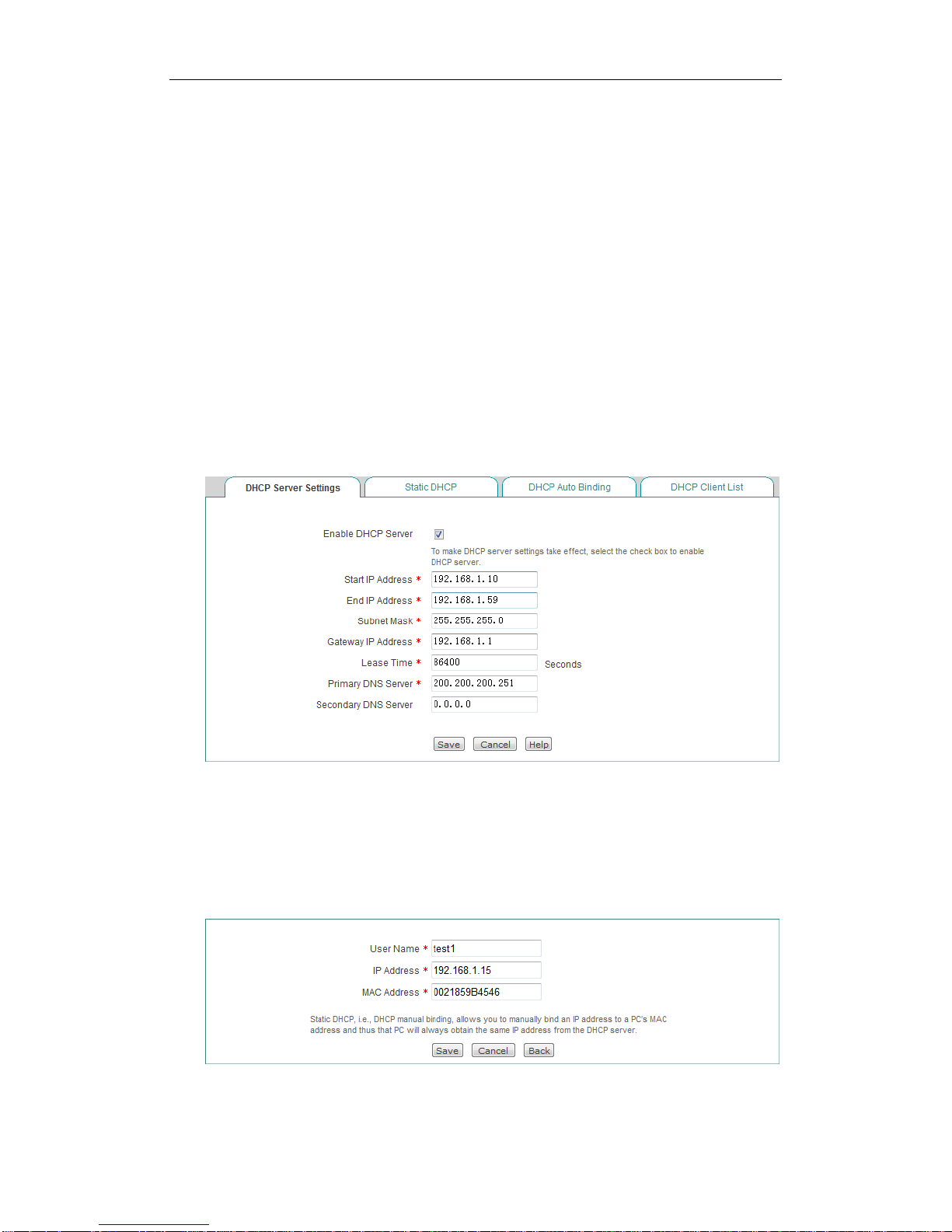
4.4.2.2 Static DHCP Settings
Click the Add button in the page as shown in Figure 4-15 to enter into the Static
DHCP Settings page as shown below, and then configure it.
Figure 4-16 Static DHCP settings
User Name: Specify a unique name for the static DHCP entry.
IP Address: Specify the reserved IP address, which must be the valid IP address
within the range of IP addresses assigned by the DHCP server.
MAC Address: Specify the MAC address of the computer to use this reserved IP
address in a fixed way.
Note:
1) After the setting is successful, the Device will assign the preset IP address for the
specified computer in a fixed way.
2) The assigned IP addresses must be within the range provided by the DHCP
server.
If the hosts change frequently on the local area network, it is very troublesome to
configure static DHCP entries manually. And it will cause some users who can’t access
the Device and Internet. To deal with these issues, the Device provides DHCP auto
binding feature.
Once the DHCP auto binding is enabled, the Device will immediately scan the LAN to
detect active hosts connected to the Device, learn dynamic ARP information and bind
the related valid IP and MAC address as a static DHCP entry.

}
Figure 4-17 DHCP Auto Binding
Enable DHCP Auto Binding: If selected, once a LAN host obtains an IP address
from the Device that acts as a DHCP server, the Device will immediately bind the
host’s IP and MAC address as a static DHCP entry.
Enable DHCP Auto Deleting: If selected, the Device will automatically delete the
static DHCP entry when the corresponding host releases the IP address
initiatively or its lease time expires.
When acting as a DHCP client, the Device can dynamically obtain an IP address and
other TCP/IP configuration parameters from a DHCP server. The information of those
DHCP clients who have obtained an IP address and other TCP/IP configuration
parameters will be display in the DHCP Client List. Such as in the following figure,
the DHCP server assigns the IP address of 192.168.1.100 in the address pool to the
network computers whose MAC address is 74:D4:35:47:26:74, and the rest of the
time for the computer to lease this IP address is 3,574 seconds.
Figure 4-18 DHCP Client List
}
1) Requirements
In this case, the DHCP function must be enabled on the Device, with the start IP
Address as 192.168.1.10, and a total of 50 addresses can be assigned; here, the host
with the MAC address of 00:21:85:9B:45:46 assigns the fixed IP address of
192.168.1.15, and the host with the MAC address of 00:1F:3C:0F:07:F4 assigns the
fixed IP address of 192.168.1.10.
2) Configuration Steps
Step 1 Go to Network > DHCP Server > DHCP Server Settings page.
Step 2 Select Enable DHCP Server, enter 192.168.1.10 and 192.168.1.59 in the
Start IP Address and End IP Address textbox, configure other parameters
as required, and click the Save button after the end of configuration.
Figure 4-19 DHCP Server Settings_Example
Step 3 Go to Network > DHCP Server > Static DHCP page and click the Add
button.
Step 4 Configure the two static DHCP instances in the request, as shown the
following two figures.
Figure 4-20 Static DHCP Settings_Example A

}
Figure 4-21 Static DHCP Settings_Example B
At this point, the configuration is complete, and you can view the information about 2
static DHCP entries in the Static DHCP List, as shown in the following figure.
Figure 4-22 Static DHCP List_Example
4.5 DDNS
Dynamic Domain Name Service (DDNS) is a service used to map a domain name
which never changes to a dynamic IP address which may change quite often. For
example, if you have applied PPPoE connection with dynamically assigned IP
address from the ISP, you can use DDNS to allow the external computers to access
the Device by a static domain name.
In order to use DDNS service, you need to register an account with a DDNS provider.
Each DDNS provider offers its own specific network services. The DDNS service
provider reserves the right to change, suspend or terminate your use of some or all
network services at any time for any reason.
1) Register a Domain Name with no-ip.com
Please login to http://www.noip.com/ to register a domain name with the suffix of

}
no-ip.com.
2) DDNS Settings – no-ip.com
Figure 4-23 DDNS_no-ip.com
Service Provider: Select the DDNS service provider who offers services to the
Device. Here please select no-ip.com.
Host Name: Specify the host name of the Device.
User Name: Enter the user name of the account. It should be the same with the
user name that you entered when registering the DDNS account.
Password: Enter the key that you got when registering the DDNS account.
1) Register a Domain Name with no-ip.com
Please login to http://www.dyndns.org to register a domain name with the suffix of
dyndns.org.
2) DDNS Settings –dyndns.org

}
Figure 4-24 DDNS_dyndns.org
Service Provider: Select the DDNS service provider who offers services to the
Device. Here please select dyndns.org.
Host Name: Specify the host name of the Device.
User Name: Enter the user name of the account. It should be the same with the
user name that you entered when registering the DDNS account.
Password: Enter the key that you got when registering the DDNS account.
To verify whether DDNS is updated successfully, you can use the ping command at
the command prompt on the PC (for example: ping avery12345.3322.org).
If the displayed page is similar to the screenshot below, the domain name is resolved
to an IP address successfully (58.246.187.126 in this example), that is, DDNS is
updated successfully.
Note:

}
1) If your ISP assigns a private IP address (192.168.x.x, 10.x.x.x, or 172.16.x.x)
instead of a public IP address to the Device, DDNS will not work.
2) DDNS feature can help you implement VPN tunnels using dynamic IP addresses
on the Device.
4.6 UpnP
The Universal Plug and Play (UPnP) is architecture that implements zero
configuration networking, that is, it provides automatic IP configuration and dynamic
discovery of the UPnP compatible devices from various vendors. An UPnP compatible
device can dynamically join a network, obtain an IP address, announce its name,
convey its capabilities upon request, and learn about the presence and capabilities of
other devices on the network.
The Device can implement NAT traversal by enabling UPnP. When you enable UPnP,
the Device allows any LAN UPnP-enabled device to perform a variety of actions,
including retrieving the public IP address, enumerate existing port mappings, and add
or remove port mappings. By adding a port mapping, an UPnP-enabled device opens
the related service ports on the Device to allow the Internet hosts access. Windows
Messenger is an example of an application that supports NAT traversal and UPnP.
The Device provides the UPnP Port Forwarding List, which lists all the port
forwarding rules established using UPnP. You can view each port forwarding rule’s
detailed information in the list, which includes internal IP address, internal port,
protocol, remote IP address, external port, and description.
Figure 4-25 UPnP

}
4.7 Number of WAN
On the Network > Number of WAN page, you can set the number of WAN interface.
Select the number of WAN interface and click the Save button to save the settings.
Figure 4-26 Number of WAN Settings
Note:
1) After the number of WAN interface is changed, you need to restart the Device for
the setting take effect.
2) After the Device restart, all customer settings will be reset to the factory default
settings.

}
Chapter 5. Advanced Menu
5.1 NAT&DMZ
This chapter describes how to configure and use NAT features, including port
forwarding, DMZ hosts, and NAT rule.
5.1.1.1 Port Forwarding
Port forwarding can be used to set up public services on your network. When users
from the Internet make certain requests on your network, the Device can forward
those requests to computers equipped to handle the requests. For example, if you set
the port number 21 (ftp) to be forwarded to IP address 192.168.1.2, then all the
related requests from outside users will be forwarded to 192.168.1.2.
5.1.1.2 Port Forwarding List
On the Advanced > NAT & DMZ > Port Forwarding page, you can setup some port
forwarding rules.
Figure 5-1 Port Forwarding List
Add a Port Forwarding Rule: Click the Add button, then setup it, lastly click
the Save button.

}
Edit a Port Forwarding Rule: Click the Name or Edit hyperlink of this rule
entry, the related information will display in the setup fields. Then modify it,
and click the Save button.
Delete Port Forwarding Rule(s): Select the leftmost check boxes of entries,
and then click the Delete button.
5.1.1.3 Port Forwarding settings
Figure 5-2 Port Forwarding Setup
Name: Specify a name of this entry. It should be between 1 and 11 characters
long.
Enable: Select to enable this Port Forwarding entry.
Protocol: Select the transport protocol used by the service, available options are
TCP, UDP and TCP/UDP.
Start External Port: Specify the lowest port number provided by the Device. The
external ports are opened for outside users to access.
IP Address: Specify the IP address of the local server that you want outside
users to access.
Start Internal Port: Specify the lowest port number of the service provided by the
LAN host. The Start External Port and Start Internal Port can be different.
Port Count: Specify the number of ports used by the service. If the service uses
only one port number, enter 1. For example, if the start internal port is 21, the start
external port is 2001 and the port count is 10, then the internal port range is from
21 to 30, and the external port range is from 2001 to 2010.

}
Bind to: Select the NAT rule to which this port forwarding rule is bound. The port
forwarding rule will use the WAN interface’s IP address as the external IP
address.
Note: The system will automatically create some port forwarding rules. You
cannot modify or delete them.
5.1.1.4 Examples of Port Forwarding
5.1.1.4.1 Example One
An organization wants a LAN server (IP Address: 192.168.16.88) to open syslog
service (Protocol: UDP; Port: 514) to the outside users. And the Device will use 2514
as the external port and the WAN1 IP address (200.200.200.88 in this example) as
the external IP address. Then all the requests for syslog from outside users to
200.200.200.88:2514 will be forwarded to 192.168.16.88:514.
The following figure shows the detailed settings.
Figure 5-3 Port Forwarding settings - Example One
5.1.1.4.2 Example Two
An organization wants a LAN server (IP Address: 192.168.16.100) to open ftp service
(Protocol: TCP; Port: 20, 21) to the outside users. And the Device will use 2020 and
2021 as the external ports and the WAN2 IP address (200.200.201.18 in this example)
as the external IP address. As the ftp service uses two ports, so we need set the Port
Count to 2. Then all the requests for ftp from outside users to 200.200.201.18:2020 or
200.200.201.18:2021 will be forwarded to 192.168.16.100:20 or 192.168.16.100:21.
The following figure shows the detailed settings.

}
Figure 5-4 Port Forwarding Settings - Example Two
5.1.1.4.3 Example Three
An organization obtains eight public IP addresses (from 218.1.21.0/29 to
218.1.21.7/29) from the ISP. Therein, 218.1.21.1/29 is used as the Internet
connection’s gateway IP address, 218.1.21.2/29 is used as the Device’s WAN1
interface’s IP address.
The organization wants a LAN server (IP Address: 192.168.16.88) to open SMTP
service (Protocol: TCP; Port: 25) to the outside users. And the Device will use 2025 as
the external port and 218.1.21.3 as the external IP address.
Firstly, we need to create a NAT rule, and set its External IP Address to 218.1.21.3,
see section 7.1.2 NAT Rule for detailed information. Then we need to create the port
forwarding rule.
The following figure shows the detailed settings.

}
Figure 5-5 Port Forwarding Settings - Example Three
5.1.1.5 NAT Rule
5.1.1.6 Introduction to NAT
The NAT (Network Address Translation) is an Internet standard that is used to map
one IP address space (i.e., Intranet) to another IP address space (i.e., Internet). The
NAT is designed to alleviate the shortage of IP addresses, that is, it allows all the LAN
hosts to share a single or a small group of IP addresses: On the Internet, there is only
a single device using a single or a small group of public IP addresses; but the LAN
hosts can use any range of private IP addresses, and these IP addresses are not
visible from the Internet. As the internal network can be effectively isolated from the
outside world, the NAT can also provide the benefit of network security assurance.
The Device provides flexible NAT features, and the following sections will describe
them in detail.NAT Address Space Definitions
To ensure that NAT operates properly, the Device uses and maintains two address
spaces:
● Internal IP address: It indicates the IP address that is assigned to a LAN host by
the administrator. It is usually a private IP address.
● External IP address: It indicates the IP address that is assigned to the Device’s
Internet connection by the ISP. It is a legal public IP address that can represent
one or more internal IP addresses to the outside world.
5.1.1.8 NAT Types
The Device provides two types of NAT: One2One and EasyIP.

}
One2One (One to One): It indicates static network address translation. It is always
referred to as Basic NAT, which provides a one to one mapping between an internal
and an external IP address. In this type of NAT, IP address need be changed, but port
needn’t.
One to One NAT can be used to allow the outside users to access a LAN server: In
the local network, the LAN server still use the private IP address, which is provided to
the LAN hosts to access; and on the Internet, the Device will assign an external IP
address to the local server, then the outside users can using this external IP address
to access the server through the Device.
EasyIP: It indicates network address and port translation (NAPT). Since it is the most
common type of NAT, it is often simply referred to as NAT. NAPT provides
many-to-one mappings between multiple internal IP addresses and a single external
IP addresses, that is, these multiple internal IP addresses will be translated to the
same external IP address. In this type of NAT, to avoid ambiguity in the handling of
returned packets, it must dynamically assign a TCP/UDP port to an outgoing session
and change the packets’ source port to the assigned port before forwarding them.
Besides, the Device must maintain a translation table so that return packets can be
correctly translated back.
When you obtain multiple public IP addresses from your ISP, you can create more
than one NAT rule for each type of NAT. In actual network environment, different types
of NAT rules are often used together.
5.1.1.9 NAT Rule List
Figure 5-6 NAT Rule list
Add a NAT Rule: Click the Add button to go to the setup page, and then
configure it, lastly click the Save button.

}
Edit a NAT Rule: Click its Edit button, the related information will be displayed in
the setup page. Then modify it, and click the Save button.
Delete NAT Rule(s): Select the leftmost check boxes of them, and then click the
Delete button.
5.1.1.10 NAT Rule settings
5.1.1.10.1 One2One settings
Figure 5-7 One2One settings
Rule Name: Specify the name of this NAT rule entry.
NAT Type: Specify the type of the NAT rule. Here please select One2One.
Start External IP: Specify the start external IP address to which the start internal
IP address is mapped.
Start Internal IP and End Internal IP: Specify the internal address range of the
NAT rule. The LAN hosts that belong to this address range will use the NAT rule.
Bind to: Specify an Internet connection to which the NAT rule is bound. The LAN
hosts that match the NAT rule will access the Internet through this Internet
connection.
Note:
1) When creating a One2One NAT rule, you should set the Start External IP
Address, and the number of the external IP addresses is the same with the
number of internal IP addresses, which is determined by the Start Internal IP
Address and End Internal IP Address. For example, if the Start Internal IP
Address is 192.168.16.6, End Internal IP Address is 192.168.16.8, and Start
External IP Address is 200.200.200.116, then 192.168.16.6, 192.168.16.7, and
192.168.16.8 will be mapped to 200.200.200.116, 200.200.200.117, and
200.200.200.118 respectively.

}
5.1.1.10.2 EasyIP settings
Figure 5-8 EasyIP settings
Rule Name: Specify the name of this NAT rule entry.
NAT Type: Specify the type of the NAT rule. Here please select EasyIP.
External IP: Specify the external IP address to which the LAN hosts’ IP
addressed are mapped. A system reserved NAT rule’s external IP address is
0.0.0.0, which means that the rule will use the related WAN interface’s IP address
as its external IP address; and it is non-editable. A user-defined NAT rule’s
external IP address can be neither 0.0.0.0 nor the WAN interface’s IP address,
that is, you can only use the other public IP addresses provided by your ISP as its
external IP addresses.
Start Internal IP and End Internal IP: Specify the internal address range of the
NAT rule. The LAN hosts that belong to this address range will preferential use
the NAT rule.
Bind to: Specify an Internet connection to which the NAT rule is bound. The LAN
hosts that match the NAT rule will access the Internet through this Internet
connection.
5.1.1.11 Examples for NAT Rule
5.1.1.11.1 Example for Configuring One2One NAT Rule
1) Requirements
In this example, a business has a single static IP Internet connection, and obtains
eight public IP addresses (from 202.1.1.128/29 to 202.1.1.1.135/29) from the ISP.
Therein, 202.1.1.129/29 is used as the Internet connection’s gateway IP address,
202.1.1.130/2 is used as the Device’s WAN1 interface’s IP address. Note that
202.1.1.128/29 and 202.1.1.1.135/29 cannot be used as they are the subnet number
and broadcast address respectively.

}
Figure 5-9 Network Topology for One2One NAT Rule Configuration Example
The business employees will share a single public IP address of 202.1.1.130/29 to
access the Internet. The LAN’s subnet number is 192.168.16.0, and subnet mask is
255.255.255.0. And the business want to use the remaining four public IP addresses
(from 202.1.1.131/29 to 202.1.1.134/29) to create a One2One rule for the four local
servers, then the outside users can use these public addresses to access the local
servers through the Device. The four local servers IP addresses are from
192.168.16.200/24 to 192.168.16.203/24, which are mapped to 202.1.1.131/29,
202.1.1.132/29, 202.1.1.133/29, 202.1.1.134/29 respectively.
2) Analysis
Firstly we need configure a static IP Internet connection on the WAN1 interface in the
Basic > WAN page or through the Setup Wizard. After you have configured the
Internet connection, the Device will automatically create a related system reserved
NAT rule, and also enable NAT.
Secondly, we need to create a One2One NAT rule for the four local servers. After you
have configured this rule, the Device will automatically create the related static route.
3) Configuration Procedure
The configuration steps are as following:
Step 1 Go to the Advanced > NAT & DMZ > NAT Rule page, and click the Add
button to go to the setup page.
Step 2 Enter the name of this NAT rule entry in the Rule name text box and select
One2One from the NAT Type drop-down list, see the following figure.

}
Figure 5-10 One2One NAT Rule Settings - Example
Step 3 Enter 202.1.1.131 in the Start External IP text box, enter 192.168.16.200 in
the Start Internal IP text box, and enter 192.168.16.203 in the End Internal
IP text box.
Step 4 Select WAN1 from the Bind to drop-down list.
Step 5 Click the Save button to save the settings. Till now you have finished
configuring the NAT rule, and then you can view its related configuration in
the NAT Rule List.
5.1.1.11.2 Example for Configuring EasyIP NAT Rule
(1) Requirements
In this example, an Internet cafe has a single Internet connection, and obtains eight
public IP addresses (from 218.1.21.0/29 to 218.1.21.7/29) from the ISP. Therein,
218.1.21.1/29 is used as the Internet connection’s gateway IP address, 218.1.21.2/29
is used as the Device’s WAN1 interface’s IP address. Note that 218.1.21.0/29 and
218.1.21.7/29 cannot be used as they are the subnet number and broadcast address
respectively.
The administrator want the hosts in the online game area (its address range is from
192.168.16.10/24 to 192.168.16.100/24) to use 218.1.21.3/29 to access the Internet.
To achieve this purpose, he should create an EasyIP NAT rule for them. The rule’s
External IP Address is 218.1.21.3, Start Internal IP is 192.168.16.10, End Internal
IP is 192.168.16.100, and Bind to is WAN1.
(2) Configuration Procedure
The configuration steps are as following:
Step 1 Go to the Advanced > NAT & DMZ > NAT Rule page, and click the Add
button to go to the setup page.
Step 2 Enter the name of this NAT rule entry in the Rule name text box and select
EasyIP from the NAT Type drop-down list, see the following figure.

}
Figure 5-11 EasyIP NAT Rule Settings - Example
Step 3 Enter 218.1.21.3 in the External IP text box, enter 192.168.16.10 in the
Start Internal IP text box, and enter 192.168.16.100 in the End Internal IP
text box.
Step 4 Select WAN1 from the Bind to drop-down list.
Step 5 Click the Save button to save the settings. Till now you have finished
configuring the NAT rule, and then you can view its configuration in the NAT
Rule List.
5.1.1.12 DMZ
The DMZ (Demilitarized Zone) feature allows one local computer to be exposed to the
Internet for the use of a special service such as online game or video conferencing.
When receiving the requests initiated from outside users, the Device will directly
forward these requests to the specified DMZ host.
Figure 5-12 DMZ
Enable DMZ: Select to enable DMZ Host.

}
DMZ Host IP Address: Specify the private IP address of the DMZ host.
Note:
The computer designated as the DMZ host will lose firewall protection provided by the
Device. As the DMZ host is exposed to many exploits from the Internet, it may be
used to attack your network.
5.1.1.13 Priorities for Port Forwarding and DMZ Host
The port forwarding has higher priority than the DMZ host. When receiving a request
packet initiated from an outside user, the Device will firstly search the Port
Forwarding List to find out if there is a port forwarding rule matching the destination
IP address and port of the packet. If a match is found, the Device will forward the
packet to the mapped local host. Else, the Device will try to find out if there is an
available DMZ host.
5.2 Static Route
A static route is manually configured by the network administrator, which is stored in a
routing table. By using routing table, the Device can select an optimal transmission
path for each received packet, and forward the packet to the destination site
effectively. The proper usage of static routes can not only improve the network
performance, but also achieve other benefits, such as traffic control, provide a secure
network environment.
The disadvantage of using static routes is that they cannot dynamically adapt to the
current operational state of the network. When there is a change in the network or a
failure occurs, some static routes will be unreachable. In this case, the network
administrator should update the static routes manually.
5.2.1.1 Static Route List
All static routes you have configured will be displayed in the Static Route List (see
the following figure).

}
Figure 5-13 Static Route List
Add Static Route: Click the Add button, then setup it, lastly click the Save
button.
Edit Static Route: Click its Edit hyperlink, the related information will be
displayed in the setup page. Then modify it, and click the Save button.
Delete Static Route(s): Select the leftmost check boxes of them, and then
click the Delete button.
5.2.1.2 Static Route settings
Figure 5-14 Static Route setting
Route Name: Specify the name of this static route entry.
Enable: Select to enable this static route entry.

}
Destination IP: Specify the IP address of the destination network or host.
Subnet Mask: Specify the subnet mask of the destination network or host.
Gateway IP Address: Specify the IP address of the next hop router to which to
forward the packets.
Priority: Specify the priority of the static route. If there are multiple routes to the
same destination with different priorities, the Device will choose the route with the
highest priority to forward the packets. The smaller the number, the higher the
priority.
Interface: Specify the outbound interface through which the packets are
forwarded to the next hop gateway or router. The available options are the name
of each physical interface.
Note:
1) When creating a static route, you should specify the next hop IP address by the
Gateway IP Address or Interface.
2) In most cases, please don’t modify the system reserved static route (e.g., Default,
Detect) to avoid surfing the Internet abnormally.
5.3 Policy Routing
This section describes the Advanced > Policy Routing page.
Policy Routing provides a tool for forwarding and routing data packets based on the
user-defined policies. Different from the traditional destination-based routing
mechanism, Policy Routing enables you to use policies based on source and
destination address, protocol, port, schedule, and other criteria to route packets
flexibly.

}
5.3.1.1 Policy Routing List
Figure 5-15 Policy Routing List
Enable policy routing: Select to enable Policy Routing.
Add a Policy Routing Entry: Click the Add button, then setup it, lastly click the
Save button.
Allow a PBR Entry: Select the Allow check box to enable the corresponding
Policy Routing entry. If you want to disable the Policy Routing entry temporarily
instead of deleting it, please clear the check mark.
Edit a Policy Routing Entry: Click its Edit hyperlink, the related information will
be displayed in the setup page. Then modify it, and click the Save button.
Delete Policy Routing Entry(s): Select the leftmost check boxes of them, and
then click the Delete button.
Move a Policy Routing Entry: The operation of moving a Policy Routing entry to
the front of another entry is as follows: Select the name of a Policy Routing entry
from the Rule drop-down list, and another entry’s ID from the Mode drop-down
list, lastly click the Move TO button.

}
5.3.1.2 Policy Routing settings
Figure 5-16 Policy Routing settings
Enable: Select to enable the Policy Routing entry. Only you have selected this
checkbox, the Policy Routing entries will take effect.
Policy routing name: Specify the name of this Policy Routing entry.
Interface: Specify an outbound interface through which the packets matching the
Policy Routing entry are forwarded.
Src IP: Specify the source IP addresses of the packets to which the Policy
Routing entry applies.
Destination address: Specify the destination IP addresses of the packets to
which the Policy Routing entry applies.
Protocol: Select a protocol type from the drop-down list.
Common Service: Select a common used service from the drop-down list.

}
Dest Port: Specify the start and end port numbers in the associated text boxes.
The port number is between 1 and 65535.
Schedule Settings: Specify a schedule to restrict when the Policy Routing entry
takes effect. The default value is Every Day and All Day, which means the Policy
Routing entry will be in effect always.
Note:
Policy Routing takes precedence over the Device’s normal destination-based routing.
That is, if a packet matches all the criteria (source address, destination address,
protocol type, port, etc.) specified in a Policy Routing entry, it will be forwarded
through the outbound interface specified in the Policy Routing entry. If no match is
found in the Policy Routing list, the packet will be forwarded through normal routing
channel (in other words, destination-based routing is performed).
5.4 Anti-NetSniper
This section describes Advanced > Anti-NetSniper page.
Anti-NetSniper is used to crack shared Internet access detection which can be
performed by your ISP. Don't enable this feature unless you encounter the "shared
Internet access detection" issue.
Figure 5-17 Anti-NetSniper
5.5 Plug and Play
Plug and Play is a new feature of Niveo series security firewalls. If you enable plug
and play feature on the Device, the LAN users can access the Internet through the
Device without changing any network parameters, no matter what IP address, subnet
mask, default gateway and DNS server they might have. Obviously, this feature can
greatly facilitate the users. As this feature is suitable for hotel network, we also call it
hotel special version.

}
Figure 5-18 Plug and Play
Note:
1) The LAN hosts basic TCP/IP parameters (including IP address, subnet mask,
gateway IP address, and DNS server IP address) should be set properly;
otherwise, plug and play feature cannot act on those hosts.
2) Once plug and play is enabled, the Device will automatically enable proxy ARP,
enable DNS proxy, and disable IP spoofing defense.
3) Once plug and play is enabled, the Device will allow those non-IP/MAC binding
users to access the Device and Internet.
4) The users with the same IP address cannot access the Internet at the same time.
For example, if a LAN user with IP address 1.1.1.1 has connected to the Device
to access the Internet, another user with IP address 1.1.1.1 cannot access the
Internet through the Device.
5) A LAN user’s IP address cannot be the same with the Device’s LAN/WAN
interface IP address, gateway IP address, and primary/secondary DNS server IP
address; otherwise, the user cannot access the Device and Internet.
5.6 Port Mirroring
The port mirroring allows an administrator to mirror and monitor network traffic. It
copies the traffic from the specified ports to another port where the traffic can be
monitored with an external network analyzer. Then the administrator can perform
traffic monitoring, performance analysis and fault diagnosis.

}
Figure 5-19 Port Mirroring
Enable Port Mirroring: Select to enable port mirroring.
Mirroring Port: Specify the capture port that will mirror the traffic of the mirrored
port(s).
5.7 Syslog
This section describes the Advanced > Syslog page.
Syslog is a standard protocol used to capture a lot of running information about
network activity. The Device supports this protocol and can send its activity logs to an
external syslog server. It helps the network administrator monitor, analyze and
troubleshoot the Device and network.
Figure 5-20 Syslog settings
Enable Syslog: Select to enable syslog feature.
Syslog Server IP address: Specify the IP address or domain name of the syslog
server to which the Device sends syslog messages.
Syslog Server Port: Specify the port used by the syslog server to communicate
with the Device. In most cases, please leave the default value of 514, which is a
well-known port number.

}
Syslog Message Facility: Specify the facility level used for logging. The facilities
are used to distinguish different classes of syslog messages.
Note: So far, only the Xport HiPER Manager software of UTT Technologies Co.,
Ltd. can identify the heartbeat message.
5.8 Network Sharing Menu
This section describes the function on the Network Sharing menu. Network Sharing is
a model of data storage where the digital data is stored in USB disk/SD card. The
USB disk/SD card is owned and managed by Administrator who is responsible for
keeping the data available and accessible. Users access to USB disk/SD card for
digital data.
5.9 Sharing Management
After plugging a USB/SD card into the Device, administrator could share the Data on
the USB/SD card to LAN users through the FTP function. Before you enable network
sharing, please first setup the account for users on the Network Sharing > Shared
Account page.
Click Network Sharing > Sharing Management, you will see the following figure.
Figure 5-21 Network Sharing
Enable Storage Device: Select to enable network sharing.
Enable Password Protection: If selected, LAN users must use the account
which is set on the Network Sharing > Shared Account page to access the
storage device.
Disable: Click to disable the storage device.
Eject Device: Click to eject the storage device.
Scan: Click to scan the available storage device.
Notes:

}
1) Before you eject the USB/SD card from the Device, please click the Eject Device
button first, in case of unexpected error or irreparable hardware damage.
2) It is recommended to use NTFS file system.
5.10 FTP Server
On the Network Sharing > FTP Server page, you can setup FTP server to share
data to local area users. All the sources you have shared are displayed on the Shared
Directory List.
Figure 5-22 FTP Server
Enable FTP Server: Select to enable FTP Server.
Remote Access: Select to enable remote access from WAN port.
Ftp Port: Specify the FTP server port for LAN users to access. The default value
is 21. We recommend that you do not change the default value unless absolutely
necessary.
Click the Add a new folder button or to add a new folder for data sharing or edit

}
the setting of the current folders.
Figure 5-23 FTP Server Settings
Name: Specify the name of the folder which will be display on the Shared
Directory List.
Folder: Select to share all folders.
Select Folder: Select one of the paths to share.
Notes:
1) All the changes you have made will be take effect after restart.
2) There are two ways to access FTP Server:
For local users: Double-click 'My Computer', enter ftp://xxx.xxx.xxx.xxx:21
(xxx.xxx.xxx.xxx stands for the IP address of the LAN port) in the address bar to open
the shared resources folder. Such as: when the IP address of the LAN port is
192.168.1.1, you could enter ftp://192.168.1.1:21.
For remote users: First you should ensure that the Remote Access checkbox on the
Figure 8- 2 have been selected. Double-click 'My Computer', enter ftp: \\xxx. xxx. xxx.
xxx :21 (xxx.xxx.xxx.xxx stands for the IP address of the WAN port) in the address bar
to open the shared resources folder. Such as: when the IP address of the WAN port is
172.32.90.1, you could enter ftp:// 172.32.90.1:21.

}
5.11 Shared Account
You need to add account for users to access the FTP server before enabling network
sharing.
Figure 5-24 Shared Account
Please setup the username and password for the user account before enabling
network sharing. The two default account is admin and guest. The account of admin
has the right to write and read data, and who also can upload the changes on the
volume to the server through IE. The account of guest only has the right to read data.
Click the Add new item button on the Figure 8-4 to add a new account. You should
specify the username and the password for all account.
Figure 5-25 Shared Account Settings
Account: Specify the unique name of the account.
Password: Specify the password of the account.
Confirm Password: Enter the password again.

}
Access: Grant this account the right to read or read and write. .
Enable FTP Access: Select Yes to allow this account to access FTP server,
select No to forbid this account to access FTP server.

}
Chapter 6. User Management Menu
6.1 User Status
This section describes User Management > User Status page, where you can
monitor and analyze network traffic, online behaviors of the LAN users, and current
status information of each user, including Rx/Tx rate, Rx/Tx total traffic, Internet
behavior, online time, etc.
Figure 6-1 User Behavior Analysis Pie Charts
Current Network Traffic Analysis: Displays the percentage of network traffic
made up by each application in your network.
Current Internet Application Analysis: Displays the percentage of users
engaging in various online activities in your network.

}
Clear Statistics: The system provides network traffic and Internet behavior
statistics for the current day. To reset the current statistics, click the Clear
Statistics button.
Enable Recognition: Click to enable application recognition. If enabled, the
Internet application management feature (set in App Control > Application
Control page) will take effect.
Note:
If the SVG Viewer isn’t installed on your PC, the rate chart cannot be displayed
properly. To view the rate chart, click the (Please install SVG Viewer if the page
cannot display properly.) hyperlink to download and install the SVG Viewer.
1) User Status List
In User Status List, you can view current status of each user, including online time,
Rx/Tx rate, Rx/Tx total traffic, Internet behavior, etc.
Figure 6-2 User Status List
Figure 6-3 User Status List (continued)
The first column in User Status List indicates whether a user's online activities affect
work. The color of the first column indicates the impact of different degree: Red stands

}
for Serious, Yellow stands for slight, and Green stands for normal. For a user, if the
percentage of network traffic made up by accessing shopping sites, social networking
sites, using stock software, and playing online/web games is equal to or above 70%,
his/her online activities seriously affect work. If the percentage is between 50% and
70% (below 70%), his/her online activities slightly affect work. Else, his/her online
activities don't affect work.
User Name: Shows the user name of the user.
MAC Address: Displays the MAC address of the user.
Authentication Mode: Displays the authenticaiton mode of the user.
PPPoE: The user is a PPPoE user.
WEB: The user is a Web authentication user.
IP Address: Displays the IP address of the user.
Tx/Rx Rate: Displays the upload/download speed of the user.
Tx/Rx Total: Displays the total traffic transmitted/received by the user.
Online Time: Displays the online time of the user.
User Group: Displays the user group to which the user belongs.
Internet Application: Displays the online activities of the user.
Setup: Click , and then click the Clear Statistics button to clear the Internet
behavior statistics of the user.
Remarks: If the user is a PPPoE user or Web authentication user, you can click
icon to modify the description of the user.
Auto Refresh Interval: Specify the value of the interval at which User Status
List will automatically refresh. The range is 1 to 5 seconds.
Stop Auto Refresh: Click to stop User Status List from auto refreshing.
Start Auto Refresh: Click to make User Status List automatically refresh at the
specified interval.
6.2 IP/MAC binding
To achieve network security management, you should firstly implement user
identification, and then you should implement user authorization. Section 12.2
Access Control describes how to configure and use access control rules to control

}
the Internet behaviors of the LAN users. In this section, we will describe how to
implement user identification.
The Device provides IP/MAC binding feature to implement user identification. Using
the IP/MAC address pair as a unique user identity, you can protect the Device and
your network against IP spoofing attacks. IP spoofing attack refers to that a host
attempts to use another trusted host’s IP address to connect to or pass through the
Device. The host’s IP address can easily be changed to a trusted address, but MAC
address cannot easily be changed as it is added to the Ethernet card at the factory.
The IP/MAC binding feature allows you to add the IP and MAC address pairs of
trusted LAN hosts in the IP/MAC Binding List. Note that in the IP/MAC Binding List,
you can allow or block Internet access for each IP/MAC binding user. After you have
added a LAN user’s IP and MAC address pair into the IP/MAC Binding List, if its
Allow check box is selected (check mark √ appears), it will allow the user to access
the Device and Internet, else block the user.
6.2.1.1 The Operation Principle of IP/MAC Binding
For the sake of convenience, we firstly introduce several related terms including legal
user, illegal user and undefined user.
Legal User: A legal user’s IP and MAC address pair matches an IP/MAC binding
whose Allow Internet Access check box is selected.
Illegal User: A illegal user’s IP and MAC address pair matches an IP/MAC binding
whose Allow Internet Access check box is unselected; or the IP address or MAC
address is the same with an IP/MAC binding’s, but not both.
Undefined User: An undefined user’s IP address and MAC address both are different
from any IP/MAC binding. The undefined users are all the users except legal and
illegal users.
It allows the legal users to access the Device and access the Internet through the
Device, and denies the illegal users. And the parameter of Allow Undefined LAN
PCs determines whether it allows the undefined users to access the Device and
access the Internet through the Device, that is, it will allow them if the Allow
Undefined LAN PCs check box is selected, else block them.
IP/MAC binding feature can act on the packets initiated from the LAN hosts to the
Device or outside hosts. When receiving a packet initiated from LAN, the Device will
firstly determine the sender’s identity by comparing the packet with the bindings in the
IP/MAC Binding List, and then process the packet according to the sender’s identity.
The details are as follows:
1) If the sender is a legal user, the packet will be allowed to pass, and then be further
processed by the firewall access control function module.
2) If the sender is an illegal user, the packet will be dropped immediately to prevent
IP spoofing.
3) If the sender is an undefined user, there are two cases:
(1) If the Allow Undefined LAN PCs check box is selected, the packet will be

}
allowed to pass, and then be further processed by the firewall access control
function module.
(2) Else, the packet will be dropped immediately.
For example, if the IP/MAC address pair IP 192.168.16.65 and 00:15:c5:67:41:0f is
added to the IP/MAC Binding List, and its Allow check box is selected, see the
following figure.
Figure 6-4 IP/MAC Binding List - Example One
Then, when receiving a packet initiated from LAN, the Device will process it according
to the following cases:
1) A packet with IP address 192.168.16.65 and MAC address 00:15:c5:67:41:0f is
allowed to pass, and then it will be further processed by the firewall access
control function module.
2) A packet with IP address 192.168.16.65 but with a different MAC address is
dropped immediately to prevent IP spoofing.
3) A packet with a different IP address but with MAC address 00:15:c5:67:41:0f is
dropped immediately to prevent IP spoofing.
4) A packet’s IP address and MAC address both are not defined in the IP/MAC
Binding List:

}
(1) If the Allow Undefined LAN PCs check box is selected, the packet is
allowed to pass, and then it will be further processed by the firewall access
control function module.
(2) Else, the packet is dropped.
If you want to block the user who matches the IP/MAC binding from accessing the
Device and Internet, you need unselect Allow check box, see the following figure.
Then a packet with IP address 192.168.16.65 and MAC address 00:15:c5:67:41:0f will
be dropped.
Figure 6-5 IP/MAC Binding List - Example Two
Note:
1) If you have added the IP and MAC address pair of a trusted LAN host in the
IP/MAC Binding List, and later changed this host’s IP address or MAC address,
you must also change the corresponding binding in the IP/MAC Binding List;
otherwise the host cannot access the Device and Internet. If the Allow
Undefined LAN PCs check box is unselected, you must also add the IP and
MAC address pair of any new host that you add to your network, and make sure
that its Allow check box is selected; otherwise this new host cannot access the
Device and Internet.
2) IP/MAC binding feature can only act on the packets initiated from the LAN hosts
to the Device or outside hosts, but cannot act on the packets within the LAN. If

}
you change a LAN host’s IP address or MAC address, this LAN host will be
unable to access the Device and access the Internet through the Device, but it
still can communicate with the other LAN hosts, such as, it can browse Network
Neighborhood, use windows file and printer sharing services within the LAN, and
so on.
6.2.1.2 Binding List
You can view and edit all the IP/MAC Binding entries on User Management > IP MAC
binding > Binding List page.
Add an IP/MAC Binding: Click the Add button or select the Binding Settings
tab to go to the setup page, and then configure it, lastly click the Save button.
Edit an IP/MAC Binding: Click its Edit hyperlink, the related information will be
displayed in the setup page. Then modify it, and click the Save button. The Allow
check box is used to allow or block a user matching an IP/MAC binding from
accessing the Device and Internet.
Delete IP/MAC Binding(s): Select the leftmost check boxes, and then click
Delete on the lower right corner of the IP/MAC Binding List.
Delete All: Click Delete All on the lower right corner of the list, and then click the
OK button.
Figure 6-6 IP/MAC Binding List
Allow Undefined LAN PCs: Select to allow the undefined LAN hosts from
accessing the Device and access the Internet through the Device.

}
Export: Click to download the IP/MAC binding (that is, static ARP binding) script
file to the local host. Then run the file and restart the host to add all the static ARP
entries to the host to prevent ARP spoofing.
Note: If you want to unselect the Allow Undefined LAN PCs check box to block
the undefined LAN hosts from accessing or passing through the Device, you
should make sure that you have added the IP/MAC address pair of the host that
you use to administer the Device into the IP/MAC Binding List.
6.2.1.3 Binding Settings
Figure 6-7 IP/MAC Binding Settings
Scan: If you click the Scan button, the Device will immediately scan the LAN to
detect active hosts connected to the Device, learn and display dynamic ARP
information (that is, IP and MAC address pairs). Note that if you have added a
LAN host’s IP and MAC address pair in the IP/MAC Binding List, this IP/MAC
address pair will not be displayed here.
Bind: Click it to bind all the valid IP and MAC address pairs in the list box.
Also you can manually create one or more IP/MAC bindings, the operation is as
follows: Add one or more IP/MAC address pair entries in the list box, and then
click the Bind button. The input contents are: IP Address, MAC Address and
Description, one address pair entry per line; and the input format of an address
pair entry is: IP Address<Space>MAC Address<Space>Description<Enter>.
Note that Description is an optional parameter.

}
6.2.1.4 Internet Whitelist and Blacklist
By utilizing IP/MAC binding feature, you can flexibly configure an Internet whitelist or
blacklist for the LAN users.
If you want to allow only a small number of LAN users to access the Internet, you can
configure an Internet whitelist for these users. Then only the users that belong to the
whitelist can access the Internet, and all the other users can not access.
If you want to block only a small number of LAN users from accessing the Internet,
you can configure an Internet blacklist for these users. Then only the users that
belong to the blacklist cannot access the Internet, and all the other users can access.
On the Device, a user who belongs to the whitelist is a legal user, that is, the user’s IP
and MAC address pair matches an IP/MAC binding whose Allow check box is
selected.
A user who belongs to the blacklist is an illegal user, that is, the user’s IP and MAC
address pair matches an IP/MAC binding whose Allow check box is unselected; or
the IP address or MAC address is the same with an IP/MAC binding’s, but not both.
6.2.1.5 Configure an Internet Whitelist
If you want to configure an Internet whitelist, do the following:
Step 1 Go to the User Management > IP/MAC Binding page, and then click the
Add button or select the IP/MAC Binding Settings tab to go to the setup
page.
Step 2 Specify the legal users by creating the IP/MAC bindings: Add these users’
IP and MAC address pairs into the IP/MAC Binding List. By default, an
IP/MAC binding’s Allow check box is selected, which means that the user
matching the IP/MAC binding can access the Device and Internet, so please
leave it as the default value.
Step 3 Unselect the Allow Undefined LAN PCs check box to block all the
undefined users from accessing the Device and Internet.
For example, if you want to allow a LAN user with IP address 192.168.16.68 and MAC
address 0015c5674109 to access the Device and Internet, you can add an IP/MAC
binding for he/her into the IP/MAC Binding List, see the following figure. The
binding’s Allow check box is selected by default, so please leave it as the default
value.

}
Figure 6-8 IP/MAC Binding List - Example Three
6.2.1.6 Configure an Internet Blacklist
If you want to configure an Internet blacklist, do the following:
Step 1 Go to the User Management > IP/MAC Binding page, and then click the
Add button or select the Binding Settings tab to go to the setup page.
Step 2 Specify the illegal users by creating the IP/MAC bindings. There are three
methods:
Method One: Bind each illegal user’s IP address to a MAC address which is different
from any LAN host’s in the IP/MAC Binding List.
Method Two: Bind an IP address which is different from any LAN host’s to each illegal
user’s MAC address in the IP/MAC Binding List.
Method Three: Add these users’ IP and MAC address pairs in the IP/MAC Binding
List. Unselect each IP/MAC binding’s Allow check box respectively, then the matched
users can not access the Device and Internet.
Step 3 Select the Allow Undefined LAN PCs check box to allow all the undefined
users to access the Device and Internet.
For example, if you want to block a LAN user with IP address 192.168.16.68 and MAC
address 0015c5674109 from accessing the Device and Internet, you can add the
corresponding IP/MAC binding in the IP/MAC Binding List. And then unselect the

}
binding’s Allow check box to block the user’s access to the Device and Internet, see
the following figure.
Figure 6-9 IP/MAC Binding List - Example Four
6.3 PPPoE Server
6.3.1.1 Introduction to PPPoE
The PPPoE stands for Point-to-Point Protocol over Ethernet, which uses client/server
model. The PPPoE provides the ability to connect the Ethernet hosts to a remote
Access Concentrator (AC) over a simple bridging access device. And it provides
extensive access control management and accounting benefits to ISPs and network
administrators.
The PPPoE is a network protocol for encapsulating PPP frames in Ethernet frames to
provide point-to-point connection over an Ethernet network.
6.3.1.2 PPPoE Stages
As specified in RFC 2516, the PPPoE has two distinct stages: a discovery stage and a
PPP session stage. The following describes them respectively.

}
6.3.1.3 PPPoE Discovery Stage
In the PPPoE discovery stage, a PPPoE client will find a proper server, and then build
the connection. When a client initiates a PPPoE session, it should perform discovery
to indentify the PPPoE server’s Ethernet MAC address, and establish a PPPoE
session ID.
PPPoE Client
PPPoE Server
PADI
PADO
PADR
PADS
Figure 6-10 PPPoE Discovery Stage Flows
The discovery stage includes the following four steps:
1) PADI (PPPoE Active Discovery Initiation): At the beginning, a PPPoE client
broadcasts a PADI packet to find all the servers that can be connected possibly.
Until it receives PADO packets from one or more servers. The PADI packet must
contain a service name which indicates the service requested by the client.
2) PADO (PPPoE Active Discovery Offer): When a PPPoE server receives a PADI
packet in its service range, it will send a PADO response packet. The PADO
packet must contain the server’s name, and a service name identical to the one in
the PADI, and any number of other service names which indicate other services
that the PPPoE server can offer. If a PPPoE server receives a PADI packet
beyond its service range, it cannot respond with a PADO packet.
3) PADR (PPPoE Active Discovery Request): The client may receive more than
one PADO packet as the PADI was broadcast. The client chooses one server
according to the server’s name or the services offered. Then the host sends a
PADR packet to the selected server. The PADR packet must contain a service
name which indicates the service requested by the client.
4) PADS (PPPoE Active Discovery Session- confirmation): When a PPPoE
server receives a PADR packet; it prepares to begin a PPP session. It generates
a unique PPPoE session ID, and respond to the client with a PADS packet. The
PADS packet must contain a service name which indicates the service provided
to the client.
When the discovery stage completes successfully, both the server and client know the
PPPoE session ID and the peer's Ethernet MAC address, which together define the
PPPoE session uniquely.

}
6.3.1.4 PPP Session Stage
In the PPP session stage, the server and client perform standard PPP negotiation to
establish a PPP connection. After the PPP connection is established successfully, the
original datagram are encapsulated in PPP frames, and PPP frames are encapsulated
in PPPoE session frames, which have the Ethernet type 0x8864. Then these Ethernet
frames are sent to the peer. In a PPPoE session frame, the session ID must be the
value assigned in the Discovery stage, and cannot be changed in this session.
6.3.1.5 PPPoE Session Termination
After a session is established, either the server or client may send a PADT (PPPoE
Active Discovery Terminate) packet at anytime to indicate the session has been
terminated. The PADT packet’s SESSION-ID must be set to indicate which session is
to be terminated. Once received a PADT, no further PPP packets (even normal PPP
termination packets) are allowed to be sent using the specified session. A PPP peer
should use the PPP protocol itself to terminate a PPPoE session, but can use the
PADT packet to terminate the PPPoE session if PPP cannot be used.
6.3.1.6 PPPoE Server Settings
The Device support PPPoE server to allow LAN hosts acting as the PPPoE clients to
dial up to the Device.
The Device provide rich PPPoE server features, which include PPPoE global settings,
PPPoE account settings, PPPoE User Status, Export PPPoE Accounts, Import
PPPoE Accounts and so on.
6.3.1.7 Global Settings
Figure 6-11 PPPoE Server Global Settings
Enable PPPoE Server: Select to enable PPPoE server.

}
Mandatory PPPoE Authentication: Select the Enable checkbox to let the users
access internet only after pass PPPoE authentication.
Exception Group: Select the user group who do not need to pass PPPoE
authentication also can access internet. You can configure the user group on
User Management > User Group page.
Start IP Address: Specify the starting IP address that is assigned by the PPPoE
server.
Primary DNS Server: Specify the IP address of the primary DNS server that is
available to a PPPoE client.
Secondary DNS Server: Specify the IP address of the secondary DNS server
that is available to a PPPoE client.
Allow Users to Change Password: Select to allow the PPPoE client to change
the password themselves.
PPP Authentication: Specify the PPP authentication mode by which the PPPoE
server authenticates a PPPoE client. The available options are PAP, CHAP and
Auto. In most cases, please leave the default value of Auto, which means that
the Device will automatically choose PAP or CHAP to authenticate the PPPoE
client.
Max. Sessions: Specify the maximum number of PPPoE sessions that can be
created on the Device. The maximum value of Max. Sessions depends on the
specific product model.
Note:
The steps of PPPoE client changing password is as following:
1) Open the client and dialing with user name and password.
2) After dialing success, please login to page: http://192.168.1.1/poeUsers.asp (Note
the IP address is LAN’s IP).
3) Enter the user name, old password, new password, confirmed password and click
the Save button to save the changing.
4) Client could change password 5 times every day.
5) Administrator could configure daily routine notification on the APP Control >
Notification page to inform users to change password.
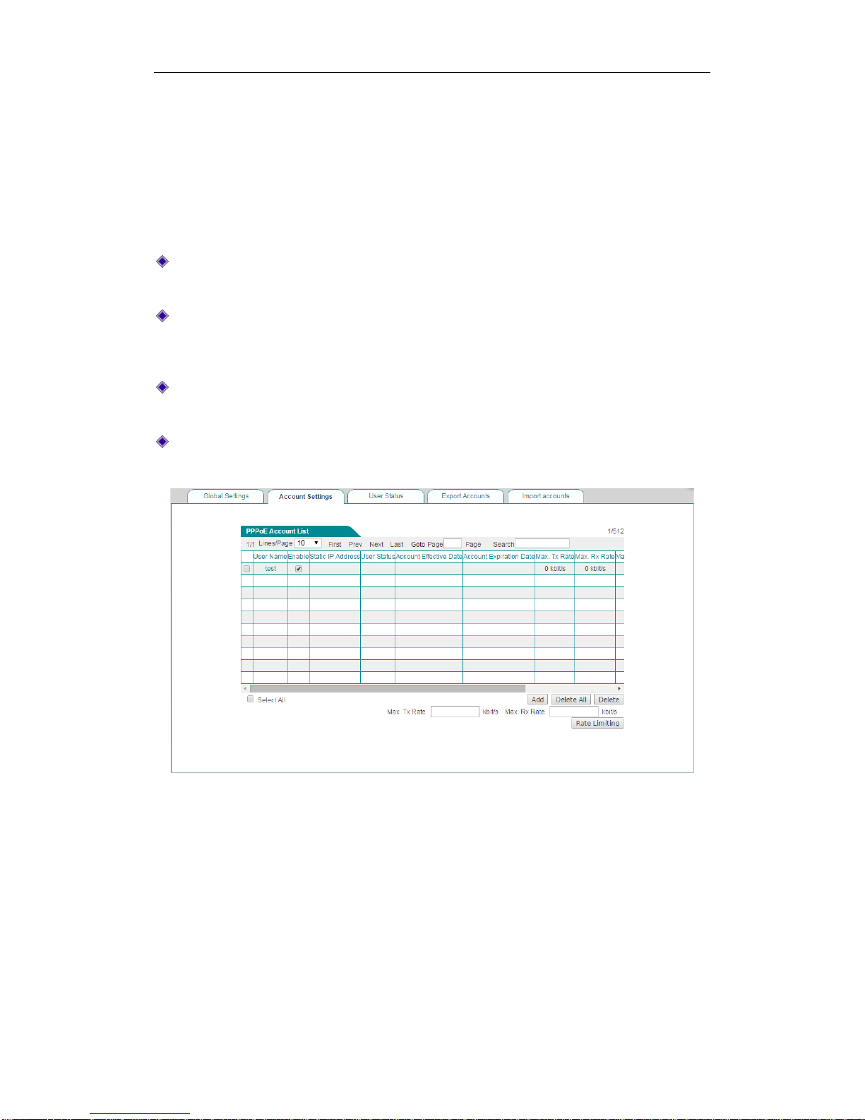
}
6.3.1.8 Account Settings
6.3.1.8.1 PPPoE Account List
When you have configured some PPPoE accounts, you can view their configuration in
the PPPoE Account List, including User Name, Enable, Static IP Address, User
Status and so on.
Add a PPPoE Account: Click the Add button to go to the setup page, and then
configure it, lastly click the Save button.
Enable a PPPoE Account: Select the Enable check box to enable the
corresponding PPPoE account. If you want to disable the PPPoE account
temporarily instead of deleting it, please click it to remove the check mark.
Edit a PPPoE Account: Click the Edit hyperlink, the related information will be
displayed in the setup page. Then modify it, and click the Save button.
Delete PPPoE Account(s): Select the leftmost check boxes of them, and then
click the Delete button.
Figure 6-12 PPPoE Account List
6.3.1.8.2 PPPoE Account Settings
In the PPPoE > Account Settings page, you can configure PPPoE account related
parameters, which include basic parameters, rate limit parameters and so on.

}
Figure 6-13 PPPoE Account Settings
User Name: Specify a unique user name of the PPPoE account. It should be
between 1 and 31 characters long. The PPPoE server will use User Name and
Password to identify the PPPoE client.
Password: Specify the password of the PPPoE account.
MAC Binding: Specify the type of PPPoE account and MAC address binding.
The available options are None, Auto and Manual.
None: If selected, a PPPoE client with any MAC address can use the current
PPPoE account to dial up.
Auto: If selected, the Device will automatically bind the PPPoE account to
the MAC address of the user who uses this account to establish a PPPoE
session firstly. After that only this user can use the account.
Manual: If selected, you can configure up to four MAC addresses that are
bound to the account. Only the users with one of these MAC addresses can
use the account.
MAC Address: Specify the MAC address that is bound to the current PPPoE
account. If you select Manual from the MAC Binding drop-down list, this
parameter will be displayed. In this case, you should enter a MAC address that is
bound to the account in the text box.
Max. Sessions: Specify the maximum number of PPPoE sessions that can be
created by using the current PPPoE account.
Static IP Address: Specify a static IP address that is assigned to the user who
uses the current PPPoE account. It must be a valid IP address in the range of
address pool configured in the PPPoE > Global Settings page.

}
Select Account Group: Add the account to the selected account group. The
account group should be set on the User Management > User Group page.
Accounting Mode: The Device support Account Billing of PPPoE Server. It
offers account billing based on time. You can configure account expiration notice
on the APP Control > Notification > Account Expiration Notification page.
Account Effective Date: Select the day of account take effect.
Account Expiration Date: Select the day of account expire.
Max. Tx Rate: Specify the maximum upload bandwidth of a PPPoE dial-in user
that uses the current PPPoE account.
Max Rx Rate: Specify the maximum download bandwidth of a PPPoE dial-in user
that uses the current PPPoE account.
Remarks: Specify the description of the PPPoE account.
Note:
1) If you want to assign a static IP address to the user that uses a PPPoE account to
establish a PPPoE session, you should enter the IP address in theStatic IP
Address text box, and should set the Max. Sessions to 1.
2) Fixed Rate Limiting is no effect to PPPoE account after you have configure Tx/Rx
Rate.
6.3.1.9 User Status
In the PPPoE > User Status page, you can view the status and usage information of
each online PPPoE dial-in user. If a PPPoE dial-in user has established the PPPoE
session to the Device successfully, you can view the assigned IP address, MAC
address, Rx Rate and Tx Rate of the user, online time and session ID of the PPPoE
session.

}
Figure 6-14 PPPoE User Status List
User Name: Displays the PPPoE user name. The PPPoE dial-in user uses it to
dial-up and establish the PPPoE session to the Device.
IP Address: Displays the PPPoE dial-in user’s IP address that is assigned by the
PPPoE server.
MAC Address: Displays the PPPoE dial-in user’s MAC address.
Online Time: Displays the elapsed time since the PPPoE session was
established successfully.
Rx Rate: Displays the real-time download rate (in kilobytes per second) of the
PPPoE dial-in user.
Tx Rate: Displays the real-time upload rate (in kilobytes per second) of the
PPPoE dial-in user.
User Status: Displays the PPPoE account status. If a PPPoE dial-in user has
established the PPPoE session to the Device successfully with the PPPoE
account, it displays Connected; Else, it displays Disconnected.
Session ID: Displays the session ID of the PPPoE Session, which uniquely
identifies a PPPoE session.
Remark: Displays the description of the PPPoE user status.
Disconnect: If you want to hang the established PPPoE session up manually,
select the leftmost check box of this PPPoE session, and then click the
Disconnect button.
Refresh: Click to view the latest information in the list.
6.3.1.10 Export Accounts
The PPPoE > Export Accounts page provides PPPoE accounts export function to
simplify operation. Click the Export Accounts button to export accounts in txt format.
Figure 6-15 Export PPPoE accounts

}
Figure 6-16 Export PPPoE accounts
6.3.1.11 Import Accounts
The PPPoE > Import Accounts page provides PPPoE accounts import function to
simplify operation. When you want to create a great deal of PPPoE accounts, you can
import them at a time in the page. You can edit them in Notepad, and then copy them
to the Import Accounts list box; also you can directly enter them in the Import
Accounts list box. The import contents are: User Name, Password, and Description
of each PPPoE account, one PPPoE account per line; and the import format of a
PPPoE account is: User Name<Space>Password<Space>Description<Enter>.
Figure 6-17 Import PPPoE accounts
Save: After you have entered the PPPoE accounts in the Import Accounts list
box, click the Save button to save them to the Device, and then you can view
them in the PPPoE Account List.
Note: To avoid unnecessary data loss due to computer crashes, you can copy
the entered PPPoE accounts to a Notepad file in your local PC before saving
them to the Device.

}
6.3.1.12 Example for PPPoE
1) Requirements
In this example, an organization’s administrator wants the LAN users to act as the
PPPoE clients to dial up to the Device. And it only allows the PPPoE dial-in users to
access the Internet through the Device. The exception is the CEO with IP address
192.168.16.2.
When acting as a PPPoE server, the Device dynamically will assign the IP addresses
to the LAN users. The start IP address assigned to the dial-in user is 10.0.0.1, the
primary DNS server IP address is 202.101.10.10, and the maximum number of
PPPoE sessions that can be created on the Device is 100.
The administrator need to create two PPPoE accounts: one is universal account
which is used by the normal employees, and its Rx and Tx bandwidth are both 512
Kbit/s, its Max. Sessions is 90; the other is advanced account which is used only for
MAC address 0021859b4544 with a static IP address 10.0.0.50.
2) Configuration Procedure
(1) Configuring PPPoE Server Global Parameters
Go to the PPPoE > Global Settings page. Select the Enable PPPoE Server check
box, select the Mandatory PPPoE Authentication check box, and select CEO from
the Exception Group drop-down list. The CEO address group only includes one IP
address: 192.168.16.2, which is configured in the User Management > User Group
page. Enter 10.0.0.1 in the Start IP Address, enter 202.101.10.10 in the Primary
DNS Server, and enter 100 in the Max. Sessions text box. Leave the default values
for the other parameters. Then click the Save button to save the settings.
Figure 6-18 PPPoE Server Global Settings - Example
(2) Configuring PPPoE Accounts

}
Step 1 Go to the PPPoE > PPPoE Account > PPPoE Account Settings page.
Step 2 Creating the universal PPPoE Account whose user name is All. See the
following figure, enter All in the User Name, enter test in the Password,
enter universalaccount in the Remarks, enter 512 in the Tx Bandwidth
and Rx Bandwidth, and enter 90 in the Max. Sessions text box. Leave the
default values for the other parameters. Then click the Save button to save
the settings.
Figure 6-19 Configuring the Universal PPPoE Account - Example
Step 3 Creating the advanced PPPoE Account whose user name is Advanced. See
the following figure, enter Advanced in the User Name, enter test2 in the
Password, enter advanced account in the Remarks, and enter
0021859b4544 in the MAC Address, enter 1 in the Max. Sessions text box,
enter 10.0.0.50 in the Static IP Address. Leave the default values for the
other parameters. Then click the Save button to save the settings.

}
Figure 6-20 Configuring the Advanced PPPoE Account - Example
6.4 Web Authentication
The Device provide Web authentication feature. This new feature will enhance
network security. If you enable the Web authentication on the Device, those
non-PPPoE dial-in users cannot access the Internet through the Device unless they
are authenticated successfully through Web browser.

}
6.4.1.1 Global Settings
Figure 6-21 Global Settings
Enable Web Authentication: If selected, non-PPPoE dial-in users cannot
access the Internet through the Device unless they are authenticated
successfully.
Enable the Background Picture: Select to enable setting a background picture
on the web authentication page.
Allow Users to Change Password: Select to enable users change password
themselves. You can set the user group on User Management > User Group
page.
Expiration Time: Specify how long the user will be log off, if there is no traffic
after the user logging in.
Exception IP Group: Select the user groups that don’t need web authentication
also can access internet.
Contact Details: Enter the contact information you want to put at the below web
authentication page.
Background Picture: Paste the background picture’s URL on the text box and
click the Save button to save the settings. You can click the Preview button to
preview the web authentication page.
6.4.1.2 Account Settings
All the web authentication account you have set will be displayed on this page.

}
Figure 6-22 Web Authentication Account List
Click the Add button on the Figure 9-22 to go to setup page, and then configure it,
lastly click the Save button.
Figure 6-23 Web Authentication Account Settings
User Name: Specify a unique user name of the web authentication account. It
should be between 1 and 31 characters long. The Device will use the User Name
and Password to authenticate a user.
Password: Specify the password of the web authentication account.
Billing Mode: Select the check to allow billing of Web Authentication based on
time.
Start Date: Select the day of account take effect.

}
End Date: Select the day of account expire.
Total Time: Enter the total time for this account take effect.
Description: Specify the description of the web authentication account.
6.4.1.3 Client Status
On the Web Authentication > Client Status page, you can view the current status of
the web authentication accounts which have been used.
Select the leftmost checkbox of the users, and then click the Disconnect button to let
the users log off manually.
Figure 6-24 Web Authentication Client Status
6.4.1.4 The steps for using Web Authentication
If you want to use web authentication for a non-PPPoE dial-in user, do the following:
Step 1 Go to the User Management > Web Authentication > Global Settings
page, and then select the Enable Web Authentication checkbox and
Allow Users to Change Password checkbox.
Step 2 Go to User Management > Web Authentication > Account Settings
page to configure a new web authentication user account, and then click the
Save button to save the settings.
Step 3 Launch a web browser, enter an Internet domain name or IP address in the
address bar, and then press <Enter>, the Device will automatically pop up

}
an authentication login page, see the figure as following.
Figure 6-25 Web Authentication Login Page
Step 4 Enter the correct user name and password in the text boxes, and then click
the Save button, the system will pop up a prompt page.
Figure 6-26 Web Authentication Prompt Page
6.5 User Group
This section describes User Management > User Group page. You can group users
that have similar needs. There are two types of groups: Address Group and Account
Group.
1) User Group List
In User Group List, you can add, view, modify and delete the user groups.

}
Figure 6-27 User Group List
2) User Group Settings
To add a new user group, go to User Management > User Group page, next click
Add to go to User Group Settings page, and then configure it, lastly click Save.
Figure 6-28 User Group Settings
Group Name: Specify the unique name for the user group.
Group Type: Select the type of the user group, Address Group or Account
Group.
Note: The user groups cannot be nested deeper than 2. For example, if the
address group A contains the address group B, then the address group A cannot
be added to any other address group.

}
Chapter 7. App Control Menu
This chapter describes how to configure schedule, application control, QQ whitelist,
MSN whitelist, TradeManager, notification, application audit, and policy database.
7.1 Schedule
This section describes APP Control > Schedule page, you can configure and view
schedules. A schedule consists of a start date, an end date, and optional time periods.
1) Schedule List
In Schedule List, you can add, view, modify and delete schedules.
Figure 7-1 Schedule List
2) Schedule Settings
To add a new schedule entry, go to App Control > Schedule page, next click Add to
go to Schedule Settings page, and then configure it, lastly click Save.

}
Figure 7-2 Schedule Settings
Schedule Name: Specify a unique name for the schedule.
Effective Date Range: Specify the effective date range for the schedule.
Time Period 1 ~ Time Period 3: Specify further constraints of active time within
the specified date range.
7.2 Application Control
This section describes APP Control > Application Control page, you can configure
and view application management list. An application control entry consists of a date,
and application.
1) Application Management List
In App Control> Application Control page, you can enable or disable Internet
application management, and you can add, view, modify, and delete Internet
application management policies in Application Management List.

}
Figure 7-3 Application Management List
Figure 7-4 Application Management List (continued)
Enable Internet Application Management: Select the check box to enable
Internet application management.
Notes: To use this feature, you need to enable application recognition in User
Management > User Status page.

}
2) Internet Application Management Settings
To add a new application management policy, go to App Control > Application
Control page, next click Add to go to Internet Application Management Settings
page, and then configure it, lastly click Save.
Figure 7-5 Internet Application Management Settings
Group Name: Enter a unique name for the group to which the Internet application
management policy applies.

}
Network Object: Select the members of the group. You can select the IP Range
button to specify a range of IP addresses, or select the User Group button to
select a user group. The members in the group are subject to the Internet
application management policy.
IM Software, P2P Software, Block Stock Software, Network Video, Online
Game, Shopping Site, Social Networking Site, Web Game, Email, Forum and
Others: Select the applications or services that you want to block under each
category.
Schedule Settings: Select the days and times when the Internet application
management policy is in effect. By default, the policy is always in effect.
Note:
If a function option in Application Control page doesn’t have the desired effect,
please go to App Control > Policy Database page to check whether the
corresponding policy is the latest. See Section10.8 Policy Database for more
information about how to update policy.
3) Example for Application Control
Requirements
In this example, a company has four departments:
Technology Department: 192.168.1.11~192.168.1.100
Customer Service Department: 192.168.1.101~192.168.1.140
Sales Department: 192.168.1.141~192.168.1.170
Financial Department: 192.168.1.171~192.168.1.180
Now the company wants to manage employee online application. It is required that all
the Internet applications provided in Internet Application Management Settings
page are blocked during working hours (Monday to Friday, 09:00 to 18:00), and
permitted at other times including weekends. But there are two exceptions:
The CEO and vice CEO can access the Internet without any restrictions. Their IP
addresses are 192.168.16.5 and 192.168.16.9 respectively.
The Customer Service and Sales Departments’ employees need to use IM
applications to communicate with customers during working hours.
Analysis
We need to create two Internet application management policies to meet the
requirements:
 Loading...