


NGSM48T2
User Manual
48-Port 10/100/1000Base-T + 2 × 10 Gigabit SFP+ Ports
Layer 2+ Full Management Switch
Version 1.0

FCC/CE Mark Warning
FCC Warning
This Equipment has been tested and found to comply with the limits for a Class-A digital device,
pursuant to Part 15 of the FCC rules. These limits are designed to provide reasonable protection
against harmful interference in a residential installation. This equipment generates, uses, and can
radiate radio frequency energy. It may cause harmful interference to radio communications if the
equipment is not installed and used in accordance with the instructions. However, there is no
guarantee that interference will not occur in a particular installation. If this equipment does cause
harmful interference to radio or television reception, which can be determined by turning the equipment
off and on, the user is encouraged to try to correct the interference by one or more of the following
measures: Reorient or relocate the receiving antenna.
Increase the separation between the equipment and receiver.
Connect the equipment into an outlet on a circuit different from that to which the receiver is
connected.
Consult the dealer or an experienced radio/TV technician for help.
CE Mark Warning
This is a Class-B product. In a domestic environment this product may cause radio interference in
which case the user may be required to take adequate measures.
NGSM48T2 User Manual | 2

Table of Contents
Table of Contents
Before Starting ............................................................................................................................... 8
Intended Readers ......................................................................................................................... 9
Icons for Note, Caution, and Warning ......................................................................................... 9
Product Package Contents .........................................................................................................10
Chapter 1: Product Overview .................................................................................................... 11
Product Brief Description ...........................................................................................................12
Product Specification ................................................................................................ .................14
Hardware Description .................................................................................................................17
Hardware Installation ..................................................................................................................18
Chapter 2: Preparing for Management ......................................................................................19
Preparation for Serial Console ...................................................................................................20
Preparation for Web Interface ....................................................................................................22
Preparation for Telnet/SSH Interface .........................................................................................24
Chapter 3: Featuring Configuration – Web UI ..........................................................................26
System Configuration .................................................................................................................27
System Information ...................................................................................................................27
IP Configuration ........................................................................................................................28
IPv6 Configuration ....................................................................................................................30
NTP Configuration .....................................................................................................................32
Time Configuration ....................................................................................................................33
System Log Configuration ................................................................ ........................................35
Power Reduction .........................................................................................................................37
Port Configuration ......................................................................................................................39
Security Configuration: ..............................................................................................................41
Security / Switch ........................................................................................................................41
Security / Switch / Users Configuration .................................................................................41
Security / Switch / Privilege Levels Configuration ................................................................43
Security / Switch / Auth Method..............................................................................................45
Security /Switch / SSH Configuration.....................................................................................46
Security / Switch / HTTPS Configuration ................................ ...............................................47
Security / Switch / Access Management Configuration ........................................................48
Security / Switch / SNMP .........................................................................................................50
RMON Statistics Configuration ...............................................................................................61
Security /Network ......................................................................................................................67
Port Security Limit Control Configuration .............................................................................67
NGSM48T2 User Manual | 3

Table of Contents
Security / Network / Network Access Server Configuration .................................................71
Security / Network / Access Control List Configuration .......................................................82
Switch / Network / DHCP Configuration .................................................................................98
IP Source Guard Configuration ............................................................................................ 101
ARP Inspection ...................................................................................................................... 103
Security / AAA Authentication Server Configuration ............................................................ 105
Aggregation Configuration ................................................................................................ ....... 109
Static Aggregation ................................................................ ................................................... 109
LACP - Dynamic Aggregation ................................................................................................ . 111
Loop Protection ......................................................................................................................... 113
Spanning Tree ........................................................................................................................... 115
Spanning Tree / Bridge Setting ............................................................................................... 116
Spanning Tree / MSTI Mapping ............................................................................................... 118
Spanning Tree / MSTI Priorities ................................ .............................................................. 119
Spanning Tree / CIST Ports ..................................................................................................... 120
Spanning Tree MSTI Ports ................................................................................................ ...... 123
MVR (Multicast VLAN Registration) ......................................................................................... 124
IPMC (IP Multicast) .................................................................................................................... 126
IGMP Snooping Configuration ................................................................................................ 126
Basic Configuration ............................................................................................................... 126
IGMP Snooping VLAN Configuration ................................................................................... 129
IGMP Snooping / Port Group Filtering ................................................................................. 131
MLD Snooping Configuration ................................................................................................. 132
Basic Configuration ............................................................................................................... 132
MLD Snooping VLAN Configuration..................................................................................... 134
IPMC / MLD Snooping / Port Group Filtering ....................................................................... 136
LLDP Parameters ...................................................................................................................... 137
LLDP Configuration ................................................................................................................. 137
LLDP Media Configuration ...................................................................................................... 140
MAC Address Table Configuration ........................................................................................... 148
VLAN (Virtual LAN).................................................................................................................... 151
VLAN Membership Configuration .......................................................................................... 151
VLAN Port Configuration ................................................................................................ ........ 154
Private VLANs ........................................................................................................................... 156
Private VLAN Membership Configuration .............................................................................. 156
Port Isolation Configuration ................................................................................................... 158
VCL ............................................................................................................................................. 159
NGSM48T2 User Manual | 4

Table of Contents
VCL / MAC-Based VLAN Configuration ................................................................................. 159
VCL / Protocol-based VLAN .................................................................................................... 161
VCL / IP Subnet-based VLAN .................................................................................................. 164
Voice VLAN Configuration ........................................................................................................ 166
Voice VLAN / Configuration .................................................................................................... 166
Voice VLAN / OUI Configuration ............................................................................................. 168
QoS ............................................................................................................................................ 169
QoS / Ingress Port Classification ................................ ........................................................... 169
QoS / Ingress Port Policer Config .......................................................................................... 171
QoS / Port Scheduler ............................................................................................................... 172
QoS / Egress Port Shapers ..................................................................................................... 173
QoS / Port Tag Remarking ...................................................................................................... 174
QoS / Port DSCP Configuration .............................................................................................. 175
QoS / DSCP based QoS Ingress Classification ................................ ..................................... 177
QoS / DSCP Translation .......................................................................................................... 178
QoS / DSCP Classification ...................................................................................................... 180
QoS / Control List Configuration ............................................................................................ 181
QoS / Storm Control Configuration ........................................................................................ 184
Mirroring Configuration ............................................................................................................ 185
UPnP Configuration .................................................................................................................. 187
sFlow Configuration.................................................................................................................. 188
Chapter 4: Feature Configuration - CLI ................................................................................... 190
System Configuration ............................................................................................................... 192
Power Reduction ....................................................................................................................... 199
Port Configuration .................................................................................................................... 201
Security Configuration .............................................................................................................. 204
Aggregation Configuration ................................................................................................ ....... 224
Loop Protection ......................................................................................................................... 226
Spanning Tree ........................................................................................................................... 227
MVR ............................................................................................................................................ 231
IPMC ........................................................................................................................................... 233
LLDP Configuration .................................................................................................................. 236
MAC Address Table Configuration ........................................................................................... 238
VLAN Configuration .................................................................................................................. 240
Private VLAN Configuration ..................................................................................................... 241
VCL Configuration..................................................................................................................... 242
Voice VLAN Configuration ........................................................................................................ 244
NGSM48T2 User Manual | 5

Table of Contents
QoS Configuration .................................................................................................................... 246
Mirroring Configuration ............................................................................................................ 250
UPnP Configuration .................................................................................................................. 251
sFlow Configuration.................................................................................................................. 252
Diagnostic Commands ............................................................................................................. 254
Maintenance Commands .......................................................................................................... 256
Chapter 5: Web Configuration - Monitor, Diagnostic, Maintenance ...................................... 258
Monitor ....................................................................................................................................... 259
Monitor / System ..................................................................................................................... 259
Monitor / System / Information ............................................................................................. 259
CPU Load ............................................................................................................................... 261
System Log Information ........................................................................................................ 262
System / Detailed Log............................................................................................................ 263
Monitor / Port State ................................................................................................................. 264
Port State ................................................................................................................................ 264
Traffic Overview ..................................................................................................................... 265
QoS Statistics ........................................................................................................................ 266
QCL Status ............................................................................................................................. 267
Detailed Port Statistics .......................................................................................................... 269
Monitor / Security .................................................................................................................... 271
Security / Access Management Statistics ............................................................................ 271
Security / Network ................................................................................................................. 272
Security / AAA ........................................................................................................................ 292
Switch / SNMP / RMON .......................................................................................................... 300
LACP System Status ............................................................................................................... 306
System Status ........................................................................................................................ 306
LACP Port Status ................................................................................................................... 307
LACP statistics ...................................................................................................................... 308
Loop Protection ....................................................................................................................... 309
STP Bridge Status ................................................................................................................... 310
Bridge Status ......................................................................................................................... 310
STP Port Status ...................................................................................................................... 311
STP Port Statistics ................................................................................................................. 312
MVR Status .............................................................................................................................. 313
Statistics ................................................................................................................................. 313
MVR Group Table ................................................................................................................... 314
Monitor / IPMC / IGMP Snooping ............................................................................................ 315
NGSM48T2 User Manual | 6

Table of Contents
IGMP Snooping ...................................................................................................................... 315
MLD Snooping Status ............................................................................................................ 321
Monitor / LLDP ......................................................................................................................... 325
LLDP / Neighbor..................................................................................................................... 325
LLDP MED Neighbors ............................................................................................................ 327
LLDP EEE ............................................................................................................................... 331
LLDP Statistics ...................................................................................................................... 333
Dynamic MAC Table ................................................................................................................ 335
VLAN Membership Status ....................................................................................................... 337
VCL MAC-Based VLAN Status ................................................................................................ 341
sFlow ........................................................................................................................................ 342
Diagnostic .................................................................................................................................. 343
Ping .......................................................................................................................................... 343
Ping6 ........................................................................................................................................ 344
VeriPHY Cable Diagnostic ....................................................................................................... 345
Maintenance .............................................................................................................................. 347
Restart Device ......................................................................................................................... 347
Factory Defaults ...................................................................................................................... 347
Software Upload ...................................................................................................................... 348
Firmware Update .................................................................................................................... 348
Image Select .......................................................................................................................... 349
Configuration ........................................................................................................................... 350
Appendix A: Product Safety ....................................................................................................... 352
Appendix B: IP Configuration for Your PC ................................................................................ 353
NGSM48T2 User Manual | 7

Before Starting
In Before Starting:
This section contains introductory information, which includes:
Intended Readers
Icons for Note, Caution, and Warning
Product Package Contents
NGSM48T2 User Manual | 8

Before Starting
A Note icon indicates important information which will guide you to use this
product properly.
A Caution icon indicates either a potential for hardware damage or data loss,
including information that will guide you to avoid these situations.
A Warning icon indicates potentials for property damage and personal injury.
Intended Readers
This manual provides information regarding to all the aspects and functions needed
to install, configure, use, and maintain the product you’ve purchased.
This manual is intended for technicians who are familiar with in-depth concepts of
networking management and terminologies.
Icons for Note, Caution, and Warning
To install, configure, use, and maintain this product properly, please pay attention
when you see these icons in this manual:
NGSM48T2 User Manual | 9

Before Starting
One Network Switch
One Power Cord
One User Manual CD
One pair Rack-mount kit + 8 Screws
Product Package Contents
Before starting install this product, please check and verify the contents of the
product package, which should include the following items:
Note: If any item listed in this table above is missing or damaged, please contact
your distributor or retailer as soon as possible.
NGSM48T2 User Manual | 10

Chapter 1:
Product Overview
In Product Overview:
This section will give you an overview of this product, including its feature functions
and hardware/software specifications.
Product Brief Description
Product Specification
Hardware Description
Hardware Installation
NGSM48T2 User Manual | 11

Chapter 1: Product Overview
Product Overview
Product Brief Description
Introduction
The switch is 48-port 10/100/1000Base-T + 2 × 10 Gigabit SFP+ Ports
Rack-mount L2+ Full Management Network Switch that is designed for medium or
large network environment to strengthen its network connection. The switch
supports 136G non-blocking switch fabric, the 48 gigabit ports and 2 10G uplink
ports can transmit and receive data traffic without any lost. The EEE feature reduces
the power consumption when there is no traffic forwarding even port is still
connected. The switch also supports Layer 2+ full management software features.
These features are powerful to provide network control, management, monitor and
security feature requests. Including rack-mount brackets, the 19" size fits into your
rack environment. It is a superb choice to boost your network with better
performance and efficiency.
2 10 Gigabit SFP+ Open Slots
The switch equips with 2 10G SFP+ open slots as the uplink ports, the 10G uplink
design provides an excellent solution for expanding your network from 1G to 10G. By
10G speed, this product provides high flexibility and high bandwidth connectivity to
another 10G switch or the Servers, Workstations and other attached devices which
support 10G interfaces. The user can also aggregate the 10G ports as Trunk group
to enlarge the bandwidth.
Full Layer 2 Management Features
The switch includes full Layer 2+ Management features. The software set includes
up to 4K 802.1Q VLAN and advanced Protocol VLAN, Private VLAN,
MVR…features. There are 8 physical queues Quality of Service, IPv4/v6 Multicast
filtering, Rapid Spanning Tree protocol to avoid network loop, Multiple Spanning
Tree Protocol to integrate VLAN and Spanning Tree, LACP, LLDP; sFlow, port
mirroring, cable diagnostic and advanced Network Security features. It also provides
Console CLI for out of band management and SNMP, Web GUI for in band
Management.
NGSM48T2 User Manual | 12

Chapter 1: Product Overview
Product Overview
Advanced Security
The switch supports advanced security features. For switch management, there are
secured HTTPS and SSH, the login password, configuration packets are secured.
The port binding allows to bind specific MAC address to the port, only the MAC has
the privilege to access the network. The 802.1X port based Access Control, every
user should be authorized first when they want to access the network. AAA is the
short of the Authentication, Authorization and Accounting with RADIUS, TACAS+
server. Layer 2+ Access Control List allows user to define the access privilege
based on IP, MAC, Port number, and etc.
NGSM48T2 User Manual | 13

Chapter 1: Product Overview
Standard
Ethernet: IEEE 802.3, 802.3u, 802.3ab, 802.3ae
IEEE 802.3az Energy Efficient Ethernet (EEE)
Protocol: IEEE 802.3x - Flow Control, IEEE 802.1Q – VLAN,
IEEE 802.1p - Class of Service, IEEE 802.1D - Spanning
Tree, IEEE 802.1w - Rapid Spanning Tree, IEEE 802.1s Multiple Spanning Tree, IEEE 802.3ad - Link Aggregation
Control Protocol (LACP), IEEE802.1v - Protocol VLAN, IEEE
802.1AB - LLDP (Link Layer Discovery Protocol), IEEE
802.1X - Access Control
Interface
Number of Port: 50
10/100/1000Base RJ-45 Port : 48, Auto-negotiation, Auto
MDI/MDIX
10G SFP+ : 2
Performance
Switching Capacity: 136G bps
MAC Address Table Size: 64K
Forwarding Rate: 10G port – 14,880,000pps
1000Mbps port - 1,488,000pps
100Mbps port - 148,800pps
10Mbps port - 14,880pps
Packet Buffer: 64Mb
Product Overview
Product Specification
NGSM48T2 User Manual | 14

Chapter 1: Product Overview
L2 Features
Flow Control: 802.3x (Full-duplex)ort/ Back-Pressure
(Half-duplex)
Spanning Tree:
IEEE 802.1D-2004(Includes IEEE 802.1w): Rapid
Spanning Tree Protocol
802.1s Multiple Spanning Tree Protocol
Loop Detection
VLAN:
IEEE 802.1Q Tagged Based, Max. VLAN Group: 4K
QinQ
Port-based VLAN
Voice VLAN
Private VLAN
MVR
MAC-Based VLAN
Protocol-Based VAN
Link Aggregation:
IEEE 802.3ad with LACP: 26 trunks/ up to 8 port per trunk
Static Trunk: 26 trunks/ up to 8 port per trunk
Max. Group:26
Max. Ports/Group:8
IGMP Snooping:
IGMP Snooping v1/v2/v3
IPv6 MLD Snooping v1/v2
Queries support/ IGMP Filtering, IGMP Leave Proxy,
Immediate Leave
Storm Control: Broadcast/ Multi-cast/ Un-known Unicast
Jumbo Frame Support: 10K
QoS Features
Number of Priority queue: 8 queues/ port
Scheduling for priority queue : WRR/Strict Priority
scheduling/Hybrid
CoS :
802.1p/ IP Precedence/ IP TOS Precedence
IP DSCP/ Port based Priority
Rate Limiting: Ingress/Egress: 1Kbps/ 1pps granularity
DiffServ (RFC2474) remarking
Product Overview
NGSM48T2 User Manual | 15

Chapter 1: Product Overview
Security
User Name / Password Protection
User Privilege: up to 15 levels
IEEE 802.1x: Port-based Access Control
IP Source Guard
MAC Based Authentication
Web-based Authentication
HTTPS
SSHv2
RADIUS: Authentication/ Accounting
TACACS+: Authentication
ACL (Access control list)
Management
Command Line Interface (CLI)
Web Based Management
Telnet
Access Management Filtering: SNMP/
WEB/SSH/TELNET/
SNMP: v1/v2c/v3
RMON: RMON (1,2,3, & 9 groups)
DHCP: Client/ Relay/ Option82/ Snooping
Event/Error Log: Local Flash/ Remote Server
Software Download/ Upgrade: HTTP
Configuration Download / Upload
sFlow
Port Mirroring: One to One/ Many to One
Remote Ping
NTP/LLDP
UPnP
EEE Configuration
Cable Diagnostics
IPv6 Configuration
Power Input
100~240VAC
Mechanical
Dimension mm(H*W*D) : 44*440*331
Weight : 3.0 kg
Operating Temperature
0~40℃
Humidity
5~90% (non-condensing)
Product Overview
NGSM48T2 User Manual | 16

Chapter 1: Product Overview
LED
Color / Status
Description
No. of LEDs
10/100/1000M
Green On
Link Up
1~48
Green Blinking
Data Activating
SFP+
Green On
Fiber Connected
49~50
Green Blinking
Receiving/Transmitting
Data
49~50
Product Overview
Hardware Description
This section mainly describes the hardware of the switch and gives a physical and
functional overview.
Front Panel
The front panel of the switch consists of 48 10/100/1000 Base-TX RJ-45 ports and 2
10 Gigabit SFP+ ports. The LEDs are also located on the front panel.
LED Indicators
The LED Indicators present real-time information of systematic operation status.
Each of the switch’s RJ45 port has two LEDs, the green LED indicates RJ45
connection status/data link.
Also, port 49 and port 50 (SFP+ Ports) has their own LEDs that indicate data link
status as shown in the figure below:
Please see the table down below for detailed descriptions regarding to LED status:
Rear Panel
The rear panel of the switch contains 2 ventilation fans, a power switch, and a IEC
60320 plug for power supply.
NGSM48T2 User Manual | 17

Chapter 1: Product Overview
Product Overview
Hardware Installation
To install the switch, please place it on a large flat surface with a power socket close
by. This surface should be clean, smooth, and level. Also, please make sure that
there is enough space around the switch for RJ45 cable, power cord and ventilation.
If you’re installing this switch on a 19-inch rack, please make sure to use the
rack-mount kit (L brackets) and screws come with the product package. All screws
must be fastened so the rack-mount kit and your product are tightly conjoined before
installing it on your 19-inch rack.
Ethernet cable Request
The wiring cable types are as below.
10 Base-T: 2-pair UTP/STP Cat. 3, 4, 5 cable, EIA/TIA-568 100-ohm (Max. 100m)
100 Base-TX: 2-pair UTP/STP Cat. 5 cable, EIA/TIA-568 100-ohm (Max. 100m)
1000 Base-T: 4-pair UTP/STP Cat. 5 cable, EIA/TIA-568 100-ohm (Max. 100m)
SFP+ Installation
While install the SFP+ transceiver, make sure the SFP type of the 2 ends is the
same and the transmission distance, wavelength, fiber cable can meet your request.
It is suggested to purchase the SFP+ transceiver with the switch provider to avoid
any incompatible issue.
The way to connect the SFP+ transceiver is to Plug in SFP fiber transceiver fist. The
SFP+ transceiver has 2 plug for fiber cable, one is TX (transmit), the other is RX
(receive). Cross-connect the transmit channel at each end to the receive channel at
the opposite end.
For more information regarding to the product safety and maintenance guide, please
refer to Appendix A: Product Safety.
NGSM48T2 User Manual | 18

Chapter 2:
Preparing for Management
In Preparing for Management:
This section will guide your how to manage this product via serial console,
management web page, and Telnet/SSH interface.
The switch provides both in-band and out-band configuration methods.
Out-band Management: You can configure the switch via RS232 console cable if
you don’t attach your admin PC to your network, or if you lose network connection to
your switch. It wouldn’t be affected by network performance. This is so-called
out-band management.
In-Band Management: You can remotely manage the switch via the Web browser,
such as Microsoft Internet Explorer, or Mozilla, to configure and interrogate the
switch from anywhere on the network.
Preparation for Serial Console
Preparation for Web Interface
Preparation for Telnet/SSH Interface
NGSM48T2 User Manual | 19

Chapter 2: Preparing for Management
Preparing for Management
Preparation for Serial Console
In the package, there is one RS-232 console cable. Please attach one end of the
console cable to your PC COM port, the other end to the console port of the switch.
1. Go to Start -> Program -> Accessories -> Communication -> Hyper Terminal
2. Give a name to the new console connection.
3. Choose the COM name
4. Select correct serial settings. The serial settings of the switch are as below:
Baud Rate: 115200 / Parity: None / Data Bit: 8 / Stop Bit: 1
5. After connected, you can see Switch login request.
6. Login the switch. The default username is “admin”, password, “admin”.
Figure 3-1 Hyper Terminal Console Screen
Note: The Win 7 or later OS version doesn't provide Console Terminal tool, please
download the tool, Hyper Terminal from Microsoft web site or other terminal tools,
such as PuTTY for console connection. Type Hyper Terminal or Putty in Google web
site, thus you can find link to download it.
NGSM48T2 User Manual | 20

Chapter 2: Preparing for Management
Preparing for Management
Figure 3-2 Putty Configuration
Figure 3-3 Putty Login Screen
NGSM48T2 User Manual | 21

Chapter 2: Preparing for Management
Preparing for Management
Preparation for Web Interface
The web management page allows you to use a standard web-browser such as
Microsoft Internet Explorer, Google Chrome or Mozilla Firefox, to configure and
interrogate the switch from anywhere on the network.
Before you attempt to use the web user interface to manage switch operation, verify
that your Switch is properly installed on your network and that every PC on this
network can access the switch via the web browser.
1. Verify that your network interface card (NIC) is operational, and that your
operating system supports TCP/IP protocol.
2. Wire the switch power and connect your computer to the switch.
3. The switch default IP address is 192.168.2.1. The Switch and the connected
PC should locate within the same IP Subnet.
4. Change your computer's IP address to 192.168.2.XX or other IP address which
is located in the 192.168.2.x (For example: IP Address: 192.168.2.30; Subnet
Mask: 255.255.255.0) subnet.
NGSM48T2 User Manual | 22

Chapter 2: Preparing for Management
Preparing for Management
5. Launch the web browser and Login.
6. Launch the web browser (Internet Explorer or Mozila Firefox) on the PC.
7. Type http://192.168.2.1 (or the IP address of the switch). And then press Enter.
8. The login screen will appear next.
9. Key in the password. Default user name and password are both admin.
If you can't login the switch, the following steps can help you to identify the problem.
1. Switch to DOS command mode and type the "ipconfig" to check the NIC's setting.
Type the "ping 192.168.2.1" to verify a normal response time.
2. Check the security & firewall settings of your computer.
3. Try different Web-browser, like the Mozilla.
For more information, please refer to Appendix B: IP Configuration for Your PC.
NGSM48T2 User Manual | 23

Chapter 2: Preparing for Management
Preparing for Management
Preparation for Telnet/SSH Interface
If your Window OS is Win XP, Win 2000 or early version, you can access the Telnet
console by default command. If your OS is Window 7 or later version, please
download the terminal tool, such as HyperTeminal or Putty.
The switch support both Telnet and SSH console. The SSH console can be treated
as secured Telnet connection, need to enable the SSH feature in "Security / Switch /
SSH".
Tradition way for Telnet Connection
1. Go to Start -> Run -> cmd. And then press Enter
2. Type the Telnet 192.168.2.1 (or the IP address of the switch). And then press
Enter.
Access Telnet or SSH by Terminal tool, Putty.
1. Open Telnet/SSH Client/PuTTY
In the Session configuration, choose the Telnet/SSH in Protocol field.
In the Session configuration, enter the Host Name (IP Address of your switch) and
Port number (default Telnet =23, SSH = 22).
Then click on “Open” to start the SSH session console.
NGSM48T2 User Manual | 24

Chapter 2: Preparing for Management
Preparing for Management
2. After click on Open, then you can see the cipher information in the popup screen.
Press Yes to accept the Security Alert.
If you choose Telnet connection, there is no such cipher information and window.
It goes to next step directly.
3. After few seconds, the Telnet/SSH connection is established, the login page of
Telnet/SSH is the same as console. The command line of Telnet, SSH and
console are all the same.
NGSM48T2 User Manual | 25

Chapter 3:
Featuring Configuration – Web UI
In Featuring Configuration – Web UI:
The switch provides abundant software features, after login the switch, you can start
configuring the settings or monitoring the status. This is one question market on the
right top of the screen, you can also click the question mark to get help from the
system.
NGSM48T2 User Manual | 26
Chapter 3: Featuring Configuration – Web UI
Featuring Configuration – Web UI
System Configuration
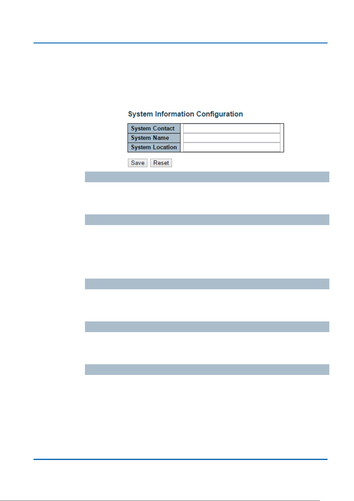
System Information
This page shows the system information and allows you to configure the new
settings.
System Contact
The textual identification of the contact person for this managed node, together with
information on how to contact this person. The allowed string length is 0 to 255, and
the allowed content is the ASCII characters from 32 to 126.
System Name
An administratively assigned name for this managed node. By convention, this is the
node's fully-qualified domain name. A domain name is a text string drawn from the
alphabet (A-Za-z), digits (0-9), minus sign (-). No space characters are permitted as
part of a name. The first character must be an alpha character. And the first or last
character must not be a minus sign. The allowed string length is 0 to 255.
System Location
The physical location of this node(e.g., telephone closet, 3rd floor). The allowed
string length is 0 to 255, and the allowed content is the ASCII characters from 32 to
126.
Time zone Offset
Provide the time zone offset relative to UTC/GMT.
The offset is given in minutes east of GMT. The valid range is from -720 to 720
minutes.
Buttons
Save: Click to save changes
Reset: Click to undo any changes made locally and revert to previously saved
values
NGSM48T2 User Manual | 27

Chapter 3: Featuring Configuration – Web UI
Featuring Configuration – Web UI
IP Configuration
Configure the switch-managed IP information on this page.
The Configured column is used to view or change the IP configuration.
The Current column is used to show the active IP configuration.
DHCP Client
Enable the DHCP client by checking this box. If DHCP fails and the configured IP
address is zero, DHCP will retry. If DHCP fails and the configured IP address is
non-zero, DHCP will stop and the configured IP settings will be used. The DHCP
client will announce the configured System Name as hostname to provide DNS
lookup.
IP Address
Provide the IP address of this switch in dotted decimal notation.
IP Mask
Provide the IP mask of this switch dotted decimal notation.
IP Router
Provide the IP address of the router in dotted decimal notation.
NTPProvide the IP address of the NTP Server in dotted decimal notation.
DNS Server
Provide the IP address of the DNS Server in dotted decimal notation.
VLAN ID
Provide the managed VLAND ID. The allowed range is 1 to 4095.
DNS Proxy
When DNS proxy is enabled, the switch will relay DNS requests to the current
configured DNS server on the switch, and reply as a DNS resolver to the client
device on the network.
NGSM48T2 User Manual | 28

Chapter 3: Featuring Configuration – Web UI
Featuring Configuration – Web UI
Buttons
Save: Click to save changes
Reset: Click to undo any changes made locally and revert to previously saved
values
Renew: Click to renew DHCP. This button is only available if DHCP is enabled.
NGSM48T2 User Manual | 29

Chapter 3: Featuring Configuration – Web UI
Featuring Configuration – Web UI
IPv6 Configuration
Configure the switch-managed IPv6 information on this page:
The Configured column is used to view or change the IPv6 configuration.
The Current column is used to show the active IPv6 configuration.
Auto Configuration
Enable IPv6 auto-configuration by checking this box. If fails, the configured IPv6
address is zero. The router may delay responding to a router solicitation for a few
seconds, the total time needed to complete auto-configuration can be significantly
longer.
Address
Provide the IPv6 address of this switch. IPv6 address is in 128-bit records
represented as eight fields of up to four hexadecimal digits with a colon separating
each field (:). For example, 'fe80::215:c5ff:fe03:4dc7'. The symbol '::' is a special
syntax that can be used as a shorthand way of representing multiple 16-bit groups of
contiguous zeros; but it can only appear once. It can also represent a legally valid
IPv4 address. For example, '::192.1.2.34'.
Prefix
Provide the IPv6 Prefix of this switch. The allowed range is 1 to 128.
Router
Provide the IPv6 gateway address of this switch. IPv6 address is in 128-bit records
represented as eight fields of up to four hexadecimal digits with a colon separating
each field (:). For example, 'fe80::215:c5ff:fe03:4dc7'.
The symbol '::' is a special syntax that can be used as a shorthand way of
representing multiple 16-bit groups of contiguous zeros; but it can only appear once.
It can also represent a legally valid IPv4 address. . For example, '::192.1.2.34'.
Buttons
Save: Click to save changes
Reset: Click to undo any changes made locally and revert to previously saved
values
Renew: Click to renew IPv6 AUTOCONF. This button is only available if IPv6
NGSM48T2 User Manual | 30

Chapter 3: Featuring Configuration – Web UI
Featuring Configuration – Web UI
AUTOCONF is enabled.
NGSM48T2 User Manual | 31

Chapter 3: Featuring Configuration – Web UI
Featuring Configuration – Web UI
NTP Configuration
NTP is short of Network Time Protocol. Network Time Protocol (NTP) is used to
synchronize time clocks on the internet. You can configure NTP Servers' IP address
here to synchronize the clocks of the remote time server on the network.
This page indicates the NTP mode operation:
Mode
The Possible modes are:
Enable NTP mode operation. When NTP mode operation is enabled, the agent
forwards NTP messages between the clients and the server when they are not on
the same subnet domain.
Disable NTP mode operation.
Server #
Provide the NTP IPv4 or IPv6 address of this switch. IPv6 address is in 128-bit
records represented as eight fields of up to four hexadecimal digits with a colon
separating each field (:). For example, 'fe80::215:c5ff:fe03:4dc7'. The symbol '::' is a
special syntax that can be used as a shorthand way of representing multiple 16-bit
groups of contiguous zeros; but it can only appear once. It can also represent a
legally valid IPv4 address. For example, '::192.1.2.34'.
Buttons
Save: Click to save changes
Reset: Click to undo any changes made locally and revert to previously saved
values
NGSM48T2 User Manual | 32

Chapter 3: Featuring Configuration – Web UI
Featuring Configuration – Web UI
Time Configuration
You can set the time of the system here in this page. The configurations available
allow you to set the time zone and daylight saving time.
Time Zone
Here you can use the scroll-down menu to set the time zone where your switch is
located.
Acronym
Here you can input the Time Zone Abbreviations. You can input up to 16 characters
here.
Daylight Saving Time
Disable or Enable the daylight saving time here with the scroll-down menu.
Start Time Settings
Input the time to start daylight saving time here.
End Time Settings
Input the time to end daylight saving time here.
NGSM48T2 User Manual | 33

Chapter 3: Featuring Configuration – Web UI
Featuring Configuration – Web UI
Offset Settings
Offset is the difference in hours and minutes from Coordinated Universal Time (UTC)
for a particular place and date. Here you can set the offset time in minutes.
Buttons
Save: Click to save changes
Reset: Click to undo any changes made locally and revert to previously saved
values
NGSM48T2 User Manual | 34

Chapter 3: Featuring Configuration – Web UI
Featuring Configuration – Web UI
System Log Configuration
System Log is useful to provide system administrator monitor switch events history.
The switch supports syslog server mode. User can install the syslog server in one
computer, then configure the server address and event types in the switch's system
log configuration. When the events occur, the switch will send information or warning
message to the syslog server. The administrator can analysis the system logs
recorded in the syslog server to find out the cause of the issues.
The switch Web UI allows you to Enable the Syslog Server, assign the IP address
and assign the syslog level.
Server Mode
Indicates the server mode operation. When the mode operation is enabled, the
syslog message will send out to syslog server. The syslog protocol is based on UDP
communication and received on UDP port 514 and the syslog server will not send
acknowledgments back sender since UDP is a connectionless protocol and it does
not provide acknowledgments. The syslog packet will always send out even if the
syslog server does not exist. Possible modes are:
Enable server mode operation.
Disable server mode operation.
Server Address
Indicates the IPv4 host address of syslog server. If the switch provide DNS feature, it
also can be a host name.
NGSM48T2 User Manual | 35

Chapter 3: Featuring Configuration – Web UI
Featuring Configuration – Web UI
Syslog Level
Indicates what kind of message will send to syslog server. Possible modes are:
Info: Send information, warnings and errors.
Warning: Send warnings and errors.
Error: Send errors.
Buttons
Save: Click to save changes
Reset: Click to undo any changes made locally and revert to previously saved
values
NGSM48T2 User Manual | 36

Chapter 3: Featuring Configuration – Web UI
Featuring Configuration – Web UI
Power Reduction
EEE Configuration:
This page allows the user to inspect and configure the current EEE port settings:
EEE is a power saving option that reduces the power usage when there is very low
traffic utilization (or no traffic).
EEE works by powering down circuits when there is no traffic. When a port gets data
to be transmitted all circuits are powered up. The time it takes to power up the
circuits is named wakeup time. The default wakeup time is 17 us for 1Gbit links and
30 us for other link speeds. EEE devices must agree upon the value of the wakeup
time in order to make sure that both the receiving and transmitting device has all
circuits powered up when traffic is transmitted. The devices can exchange
information about the devices wakeup time using the LLDP protocol.
For maximizing the power saving, the circuit isn't started at once transmit data are
ready for a port, but is instead queued until 3000 bytes of data are ready to be
NGSM48T2 User Manual | 37

Chapter 3: Featuring Configuration – Web UI
Featuring Configuration – Web UI
transmitted. For not introducing a large delay in case that data less then 3000 bytes
shall be transmitted, data are always transmitted after 48 us, giving a maximum
latency of 48 us + the wakeup time.
If desired it is possible to minimize the latency for specific frames, by mapping the
frames to a specific queue (done with QOS), and then mark the queue as an urgent
queue. When an urgent queue gets data to be transmitted, the circuits will be
powered up at once and the latency will be reduced to the wakeup time.
Port
The switch port number of the logical EEE port.
EEE Enabled
Controls whether EEE is enabled for this switch port.
EEE Urgent Queues
Queues set will activate transmision of frames as soon as any data is available.
Otherwise the queue will postpone the transmsion until 3000 bytes are ready to be
transmitted.
Buttons
Save: Click to save changes
Reset: Click to undo any changes made locally and revert to previously saved
values
NGSM48T2 User Manual | 38

Chapter 3: Featuring Configuration – Web UI
Featuring Configuration – Web UI
Port Configuration
This page displays current port configurations and link status. Some of the Ports'
settings can also be configured here.
Port
This is the port number for this row.
Link
The current link state is displayed graphically.
Green indicates the link is up and red that it is down.
Current Link Speed
Provides the current link speed of the port.
Ex: 1Gfdx: 1G indicates the Gigabit Speed, fdx indicates the Full Duplex Mode.
Configured Link Speed
Select any available link speed for the given switch port.
Auto Speed: selects the highest speed that is compatible with a link partner.
Disabled: disables the switch port operation.
Disable 10G FDX Fiber
You can disable/enable 10G FDX Fiber here.
NGSM48T2 User Manual | 39

Chapter 3: Featuring Configuration – Web UI
Featuring Configuration – Web UI
Flow Control
When Auto Speed is selected on a port, this section indicates the flow control
capability that is advertised to the link partner.
When a fixed-speed setting is selected, that is what is used. The Current Rx column
indicates whether pause frames on the port are obeyed, and the Current Tx column
indicates whether pause frames on the port are transmitted. The Rx and Tx settings
are determined by the result of the last Auto-Negotiation.
Check the configured column to use flow control. This setting is related to the setting
for Configured Link Speed.
Maximum Frame Size
Enter the maximum frame size allowed for the switch port, including FCS.
The switch supports up to 9K Jumbo Frame.
Excessive Collision Mode
Configure port transmit collision behavior.
Discard: Discard frame after 16 collisions (default).
Restart: Restart backoff algorithm after 16 collisions.
Power Control
The Usage column shows the current percentage of the power consumption per port.
The Configured column allows for changing the power savings mode parameters per
port.
Disabled: All power savings mechanisms disabled.
ActiPHY: Link down power savings enabled.
PerfectReach: Link up power savings enabled.
Enabled: Both link up and link down power savings enabled.
Buttons
Save: Click to save changes
Reset: Click to undo any changes made locally and revert to previously saved
values
Refresh: Click to refresh the page. Any changes made locally will be undone.
NGSM48T2 User Manual | 40
Chapter 3: Featuring Configuration – Web UI
Featuring Configuration – Web UI
Security Configuration:
The Security Configuration feature includes 3 sub-titles, Switch, Network and AAA.
Security / Switch
The switch settings includes User Database, Privilege Levels, Authentication
Method, SSH, HTTPs, Access Management, SNMP and RMON setting. Following
are the topic and configuration guide.
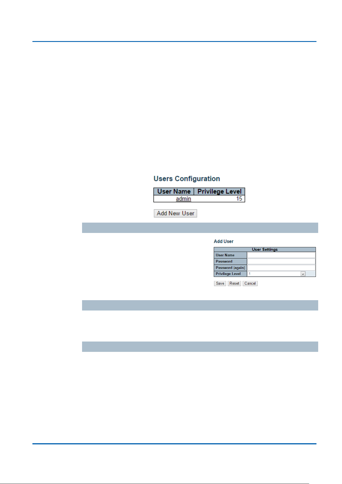
Security / Switch / Users Configuration
This page provides an overview of the current users. Currently the only way to login
as another user on the web server is to close and reopen the browser.
This page configures a user: This is also a link to Add User & Edit User
Add New User/Edit User
Click "Add New User", the configuration
page goes to "Add User" screen. You can
see the User Setting table, follow the below
instruction to fill the table.
Click the created User Name, the page goes
to "Edit User" screen, you can change the settings on it.
User Name
A string identifying the user name that this entry should belong to. The allowed string
length is 1 to 32. The valid user name is a combination of letters, numbers and
underscores.
Password
The password of the user. The allowed string length is 0 to 32.
NGSM48T2 User Manual | 41

Chapter 3: Featuring Configuration – Web UI
Featuring Configuration – Web UI
Privilege Level
The privilege level of the user. The allowed range is 1 to 15.
If the privilege level value is 15, it can access all groups, i.e. that is granted the fully
control of the device. But others value need to refer to each group privilege level.
User's privilege should be same or greater than the group privilege level to have the
access of that group.
By default setting, most groups privilege level 5 has the read-only access and
privilege level 10 has the read-write access. And the system maintenance (software
upload, factory defaults and etc.) need user privilege level 15. Generally, the
privilege level 15 can be used for an administrator account, privilege level 10 for a
standard user account and privilege level 5 for a guest account.
Check the next chapter to see how to configure privilege level.
Buttons
Add new user: Click to add a new user.
NGSM48T2 User Manual | 42

Chapter 3: Featuring Configuration – Web UI
Aggregation
Debug
Diagnostics
EEE
IP
IPMC_LIB
IPMC_Snooping
LACP
LLDP
LLDP_MED
Loop_Protect
MAC_Table
MVR
Maintenance
Mirroring
PHY
Port_Security
Ports
Private_VLANs
QoS
SNMP
Security
Spanning_Tree
Voice_VLAN
System
Timer
UPnP
VCL
VLANs
sFlow
Featuring Configuration – Web UI
Security / Switch / Privilege Levels Configuration
This page provides an overview of the privilege levels.
Group Name
The name identifying the privilege group. In most cases, a privilege level group
consists of a single module (e.g. LACP, RSTP or QoS), but a few of them contains
more than one.
The table down below lists the functions that can be set here in the privilege levels:
NGSM48T2 User Manual | 43

Chapter 3: Featuring Configuration – Web UI
Featuring Configuration – Web UI
Privilege Levels
Every group has an authorization Privilege level for the following sub groups:
configuration read-only, configuration/execute read-write, status/statistics read-only,
status/statistics read-write (e.g. for clearing of statistics).
User Privilege should be same or greater than the authorization Privilege level to
have the access to that group.
Insufficient Privilege Level: If you login with lower level privilege and try to access
the high privilege level configuration feature, the following message, Insufficient
Privilege Level will appear. If you want continue, be sure that you have the privilege.
Buttons
Save: Click to save changes
Reset: Click to undo any changes made locally and revert to previously saved
values
NGSM48T2 User Manual | 44

Chapter 3: Featuring Configuration – Web UI
Featuring Configuration – Web UI
Security / Switch / Auth Method
This page allows you to configure how a user is authenticated when he logs into the
switch via one of the management client interfaces.
The table has one row for each client type and a number of columns, which are:
Client
The management client for which the configuration below applies.
Authentication Method
Authentication Method can be set to one of the
following values:
none: authentication is disabled and login is
not possible.
local: use the local user database on the
switch for authentication.
RADIUS: use a remote RADIUS server for authentication.
TACACS+: use a remote TACACS server for authentication.
Fallback
Enable fallback to local authentication by checking this box.
If none of the configured authentication servers are alive, the local user database is
used for authentication.
This is only possible if the Authentication Method is set to a value other than 'none'
or 'local'.
Buttons
Save: Click to save changes
Reset: Click to undo any changes made locally and revert to previously saved
values
NGSM48T2 User Manual | 45

Chapter 3: Featuring Configuration – Web UI
Featuring Configuration – Web UI
Security /Switch / SSH Configuration
With SSH, you can remotely connect to the switch by command line interface. The
SSH connection can secure all the configuration commands you sent to the switch.
It is also known as secured Telnet console.
To access the switch by SSH, you should install SSH client on you computer, such
as PuTTy console tool. In the switch side, the switch acts as SSH server for user
login, and you can Enable or Disable SSH on this page.
Please check the chapter Preparation for Telnet/SSH to see how to manage the
switch through SSH console.
Mode
Indicates the SSH mode operation. Possible modes are:
Enable: Enable SSH mode operation.
Disabled: Disable SSH mode operation.
Buttons
Save: Click to save changes
Reset: Click to undo any changes made locally and revert to previously saved
values
NGSM48T2 User Manual | 46

Chapter 3: Featuring Configuration – Web UI
Featuring Configuration – Web UI
Security / Switch / HTTPS Configuration
The web management page also provides secured management HTTPS login. All
the configuration commands will be secured and will be hard for the hackers to sniff
the login password and configuration commands.
This page allows you to configure HTTPS mode.
Mode
Indicates the HTTPS mode operation. Possible modes are:
Enable: Enable HTTPS mode operation.
Disabled: Disable HTTPS mode operation.
Automatic Redirect
Indicates the HTTPS redirect mode operation. Automatically redirect web browser to
HTTPS when HTTPS mode is enabled. Possible modes are:
Enable: Enable HTTPS redirect mode operation.
Disabled: Disable HTTPS redirect mode operation.
Buttons
Save: Click to save changes
Reset: Click to undo any changes made locally and revert to previously saved
values
NGSM48T2 User Manual | 47

Chapter 3: Featuring Configuration – Web UI
Featuring Configuration – Web UI
Security / Switch / Access Management Configuration
The Access Management mode allows user to limit the switch access with specific
range of IP address and disable some remote management service, such HTTP,
HTTPS, SNMP, Telnet and SSH. This feature is important while user installed the
switch on network. After enabled the Access Management, only the pre-configured
IP address or a range of IP address can access the switch management interface,
and only the available service can be accessed.
Configure access management table on this page. The maximum entry number is
16. If the application's type match any one of the access management entries, it will
allow access to the switch.
Example of the below figure, only the IP Addresses range from 192.168.2.101 to
192.168.2.200 can access the switch's management interface. The available
services are HTTP, HTTPS, SNMP, Telnet and SSH. If there is one IP address,
192.168.2.201 try to open the web management interface, it is not allowed.
Mode
Indicates the access management mode operation. Possible modes are:
Enable: Enable access management mode operation.
Disabled: Disable access management mode operation.
Delete
Check to delete the entry. It will be deleted during the next save.
Start IP address
Indicates the start IP address for the access management entry.
End IP address
Indicates the end IP address for the access management entry.
With the Start and End IP address, you can assign a range of IP addresses.
HTTP/HTTPS
Indicates that the host can access the switch from HTTP/HTTPS interface if the host
IP address matches the IP address range provided in the entry.
NGSM48T2 User Manual | 48

Chapter 3: Featuring Configuration – Web UI
Featuring Configuration – Web UI
SNMP
Indicates that the host can access the switch from SNMP interface if the host IP
address matches the IP address range provided in the entry.
TELNET / SSH
Indicates that the host can access the switch from TELNET/SSH interface if the host
IP address matches the IP address range provided in the entry.
Buttons
Add New Entry: Click to add a new group entry
Save: Click to save changes
Reset: Click to undo any changes made locally and revert to previously saved
values
NGSM48T2 User Manual | 49

Chapter 3: Featuring Configuration – Web UI
Featuring Configuration – Web UI
Security / Switch / SNMP
Simple Network Management Protocol (SNMP) is a protocol used for exchanging
management information between network devices. The switch supports SNMP and
equips lots of OIDs for remote management. All the OIDs are unique and
corresponding to one feature/command.
The switch can support SNMP V1, V2c and V3. The following commands show how
to configure SNMP and its related parameters.
Mode
Indicates the SNMP mode operation. Possible modes are:
Enable: Enable SNMP mode operation.
Disabled: Disable SNMP mode operation.
Version
Indicates the SNMP supported version. Possible versions are:
SNMPv1: Set SNMP supported version 1.
SNMPv2c: Set SNMP supported version 2c.
SNMPv3: Set SNMP supported version 3.
Read Community
Indicates the community read access string to permit access to SNMP agent. The
allowed string length is 0 to 255, and the allowed content is the ASCII characters
from 33 to 126.
The field is applicable only when SNMP version is SNMPv1 or SNMPv2c. If SNMP
version is SNMPv3, the community string will be associated with SNMPv3
communities table. It provides more flexibility to configure security name than a
SNMPv1 or SNMPv2c community string. In addition to community string, a particular
range of source addresses can be used to restrict source subnet.
Write Community
Indicates the community write access string to permit access to SNMP agent. The
allowed string length is 0 to 255, and the allowed content is the ASCII characters
from 33 to 126.
NGSM48T2 User Manual | 50

Chapter 3: Featuring Configuration – Web UI
Featuring Configuration – Web UI
The field is applicable only when SNMP version is SNMPv1 or SNMPv2c. If SNMP
version is SNMPv3, the community string will be associated with SNMPv3
communities table. It provides more flexibility to configure security name than a
SNMPv1 or SNMPv2c community string. In addition to community string, a particular
range of source addresses can be used to restrict source subnet.
Engine ID
Indicates the SNMPv3 engine ID. The string must contain an even number(in
hexadecimal format) with number of digits between 10 and 64, but all-zeros and
all-'F's are not allowed. Change of the Engine ID will clear all original local users.
NGSM48T2 User Manual | 51

Chapter 3: Featuring Configuration – Web UI
Featuring Configuration – Web UI
SNMP Trap Configuration
Configure SNMP trap on this page.
Trap Mode
Indicates the SNMP trap mode operation. Possible modes are:
Enable: Enable SNMP trap mode operation.
Disabled: Disable SNMP trap mode operation.
Trap Version
Indicates the SNMP trap supported version. Possible versions are:
SNMPv1: Set SNMP trap supported version 1.
SNMPv2c: Set SNMP trap supported version 2c.
SNMPv3: Set SNMP trap supported version 3.
Trap Community
Indicates the community access string when sending SNMP trap packet. The
allowed string length is 0 to 255, and the allowed content is ASCII characters from
33 to 126.
Trap Destination Address
Indicates the SNMP trap destination address.
Trap Destination IPv6 Address
Provide the trap destination IPv6 address of this switch. IPv6 address is in 128-bit
records represented as eight fields of up to four hexadecimal digits with a colon
separating each field (:). For example, 'fe80::215:c5ff:fe03:4dc7'. The symbol '::' is a
special syntax that can be used as a shorthand way of representing multiple 16-bit
groups of contiguous zeros; but it can only appear once. It can also represent a
legally valid IPv4 address. For example, '::192.1.2.34'.
NGSM48T2 User Manual | 52

Chapter 3: Featuring Configuration – Web UI
Featuring Configuration – Web UI
Trap Authentication Failure
Indicates that the SNMP entity is permitted to generate authentication failure traps.
Possible modes are:
Enable: SNMP trap authentication failure.
Disabled: Disable SNMP trap authentication failure.
Trap Link-up and Link-down
Indicates the SNMP trap link-up and link-down mode operation. Possible modes are:
Enable: Enable SNMP trap link-up and link-down mode operation.
Disabled: Disable SNMP trap link-up and link-down mode operation.
Trap Inform Mode
Indicates the SNMP trap inform mode operation. Possible modes are:
Enable: Enable SNMP trap inform mode operation.
Disabled: Disable SNMP trap inform mode operation.
Trap Inform Timeout (seconds)
Indicates the SNMP trap inform timeout. The allowed range is 0 to 2147.
Trap Inform Retry Times
Indicates the SNMP trap inform retry times. The allowed range is 0 to 255.
Trap Probe Security Engine ID
Indicates the SNMP trap probe security engine ID mode of operation. Possible
values are:
Enable: Enable SNMP trap probe security engine ID mode of operation.
Disabled: Disable SNMP trap probe security engine ID mode of operation.
Trap Security Engine ID
Indicates the SNMP trap security engine ID. SNMPv3 sends traps and informs using
USM for authentication and privacy. A unique engine ID for these traps and informs
is needed. When "Trap Probe Security Engine ID" is enabled, the ID will be probed
automatically. Otherwise, the ID specified in this field is used. The string must
contain an even number(in hexadecimal format) with number of digits between 10
and 64, but all-zeros and all-'F's are not allowed.
Trap Security Name
Indicates the SNMP trap security name. SNMPv3 traps and informs using USM for
authentication and privacy. A unique security name is needed when traps and
informs are enabled.
Buttons
Save: Click to save changes
Reset: Click to undo any changes made locally and revert to previously saved
values
NGSM48T2 User Manual | 53

Chapter 3: Featuring Configuration – Web UI
Featuring Configuration – Web UI
SNMPv3 Community Configuration
In SNMP V3, it is start to support User Name and its privilege. You can configure
SNMPv3 community table on this page:
The entry index key is Community.
Delete
Check to delete the entry. It will be deleted during the next save.
Community
Indicates the community access string to permit access to SNMPv3 agent. The
allowed string length is 1 to 32, and the allowed content is ASCII characters from 33
to 126. The community string will be treated as security name and map a SNMPv1
or SNMPv2c community string.
Source IP
Indicates the SNMP access source address. A particular range of source addresses
can be used to restrict source subnet when combined with source mask.
Source Mask
Indicates the SNMP access source address mask.
Buttons
Add new community: Click to add a new community entry
Save: Click to save changes
Reset: Click to undo any changes made locally and revert to previously saved
values
NGSM48T2 User Manual | 54

Chapter 3: Featuring Configuration – Web UI
Featuring Configuration – Web UI
SNMPv3 User Configuration
Configure SNMPv3 user table on this page. The entry index keys are Engine ID and
User Name.
Delete
Check to delete the entry. It will be deleted during the next save.
Engine ID
An octet string identifying the engine ID that this entry should belong to. The string
must contain an even number(in hexadecimal format) with number of digits between
10 and 64, but all-zeros and all-'F's are not allowed. The SNMPv3 architecture uses
the User-based Security Model (USM) for message security and the View-based
Access Control Model (VACM) for access control. For the USM entry, the usm User
Engine ID and usm User Name are the entry's keys. In a simple agent, usm User
Engine ID is always that agent's own snmp Engine ID value. The value can also take
the value of the snmp Engine ID of a remote SNMP engine with which this user can
communicate. In other words, if user engine ID equal system engine ID then it is
local user; otherwise it's remote user.
User Name
A string identifying the user name that this entry should belong to. The allowed string
length is 1 to 32, and the allowed content is ASCII characters from 33 to 126.
Security Level
Indicates the security model that this entry should belong to. Possible security
models are:
NoAuth, NoPriv: No authentication and no privacy.
Auth, NoPriv: Authentication and no privacy.
Auth, Priv: Authentication and privacy.
The value of security level cannot be modified if entry already exists. That means it
must first be ensured that the value is set correctly.
NGSM48T2 User Manual | 55

Chapter 3: Featuring Configuration – Web UI
Featuring Configuration – Web UI
Authentication Protocol
Indicates the authentication protocol that this entry should belong to. Possible
authentication protocols are:
None: No authentication protocol.
MD5: An optional flag to indicate that this user uses MD5 authentication protocol.
SHA: An optional flag to indicate that this user uses SHA authentication protocol.
The value of security level cannot be modified if entry already exists. That means
must first ensure that the value is set correctly.
Authentication Password
A string identifying the authentication password phrase. For MD5 authentication
protocol, the allowed string length is 8 to 32. For SHA authentication protocol, the
allowed string length is 8 to 40. The allowed content is ASCII characters from 33 to
126.
Privacy Protocol
Indicates the privacy protocol that this entry should belong to. Possible privacy
protocols are:
None: No privacy protocol.
DES: An optional flag to indicate that this user uses DES authentication protocol.
Privacy Password
A string identifying the privacy password phrase. The allowed string length is 8 to 32,
and the allowed content is ASCII characters from 33 to 126.
Buttons
Add new user: Click to add a new user entry
Save: Click to save changes
Reset: Click to undo any changes made locally and revert to previously saved
values
NGSM48T2 User Manual | 56

Chapter 3: Featuring Configuration – Web UI
Featuring Configuration – Web UI
SNMPv3 Group Configuration
Configure SNMPv3 group table on this page:
The entry index keys are Security Mode and Security Name.
Delete
Check to delete the entry. It will be deleted during the next save.
Security Model
Indicates the security model that this entry should belong to. Possible security
models are:
v1: Reserved for SNMPv1.
v2c: Reserved for SNMPv2c.
usm: User-based Security Model (USM).
Security Name
A string identifying the security name that this entry should belong to. The allowed
string length is 1 to 32, and the allowed content is ASCII characters from 33 to 126.
Group Name
A string identifying the group name that this entry should belong to. The allowed
string length is 1 to 32, and the allowed content is ASCII characters from 33 to 126.
Buttons
Add new group: Click to add a new group entry
Save: Click to save changes
Reset: Click to undo any changes made locally and revert to previously saved
values
NGSM48T2 User Manual | 57

Chapter 3: Featuring Configuration – Web UI
Featuring Configuration – Web UI
SNMPv3 View Configuration
Configure SNMPv3 view table on this page.
The entry index keys are View Name and OID Sub-tree.
Delete
Check to delete the entry. It will be deleted during the next save.
View Name
A string identifying the view name that this entry should belong to. The allowed string
length is 1 to 32, and the allowed content is ASCII characters from 33 to 126.
View Type
Indicates the view type that this entry should belong to. Possible view types are:
Included: An optional flag to indicate that this view sub-tree should be included.
excluded: An optional flag to indicate that this view sub-tree should be excluded.
In general, if a view entry's view type is 'excluded', there should be another view
entry existing with view type as 'included' and it's OID sub-tree should overstep the
'excluded' view entry.
OID Subtree
The OID defining the root of the sub-tree to add to the named view. The allowed OID
length is 1 to 128. The allowed string content is digital number or asterisk(*).
Buttons
Add new view: Click to add a new view entry
Save: Click to save changes
Reset: Click to undo any changes made locally and revert to previously saved
values
NGSM48T2 User Manual | 58

Chapter 3: Featuring Configuration – Web UI
Featuring Configuration – Web UI
SNMPv3 Access Configuration
Configure SNMPv3 access table on this page. The entry index keys are Group
Name, Security Model, and Security Level.
Delete
Check to delete the entry. It will be deleted during the next save.
Group Name
A string identifying the group name that this entry should belong to. The allowed
string length is 1 to 32, and the allowed content is ASCII characters from 33 to 126.
Security Model
Indicates the security model that this entry should belong to. Possible security
models are:
Any: Any security model accepted(v1|v2c|usm).
V1: Reserved for SNMPv1.
V2c: Reserved for SNMPv2c.
Usm: User-based Security Model (USM).
Security Level: Indicates the security model that this entry should belong to.
Possible security models are:
NoAuth, NoPriv: No authentication and no privacy.
Auth, NoPriv: Authentication and no privacy.
Auth,Priv: Authentication and privacy.
NGSM48T2 User Manual | 59

Chapter 3: Featuring Configuration – Web UI
Featuring Configuration – Web UI
Read View Name
The name of the MIB view defining the MIB objects for which this request may
request the current values. The allowed string length is 1 to 32, and the allowed
content is ASCII characters from 33 to 126.
Write View Name
The name of the MIB view defining the MIB objects for which this request may
potentially set new values. The allowed string length is 1 to 32, and the allowed
content is ASCII characters from 33 to 126.
Buttons
Add new access: Click to add a new access entry
Save: Click to save changes
Reset: Click to undo any changes made locally and revert to previously saved
values
NGSM48T2 User Manual | 60

Chapter 3: Featuring Configuration – Web UI
RMON Group
Function
Elements
Statistics
Contains statistics measured
by the probe for each
monitored interface on this
device.
Real-time LAN statistics e.g.
utilization, collisions, CRC errors
Packets dropped, packets sent, bytes
sent (octets), broadcast packets,
multicast packets, CRC errors, undersize
packets, oversize packets, fragments,
jabbers, collisions, and counters for
packets ranging from 64, 65 to 127, 128
to 255, 256 to 511, 512 to 1023, and 1024
to 1518 bytes.
History
Records periodic statistical
samples from a network and
stores for retrieval.
History of above Statistics.
Alarm
Definitions for RMON SNMP
traps to be sent when statistics
exceed defined thresholds
Interval for sampling, particular variable,
sample type, value of statistics during the
last sampling period, startup alarm, rising
threshold, rising index, falling threshold,
falling index.
Events
Controls the generation and
notification of events from this
device.
Event index, log index, event log time,
event description
Featuring Configuration – Web UI
RMON Statistics Configuration
RMON is short of Remote Monitoring On Network. An RMON implementation
typically operates in a client/server model. Monitoring device (Probe) contains
RMON software agents that collect information of the system and ports. The RMON
software agent acts as server, and the network management system (NMS) that
communicate with it acts as client. The RMON agent of the switch supports 4 groups,
such as the Statistics, History, Alarm and Event.
The NMS can get the above information through remotely polling. The information
from the switch can be collected, analyzed and displayed as table or graphic...etc.
NGSM48T2 User Manual | 61
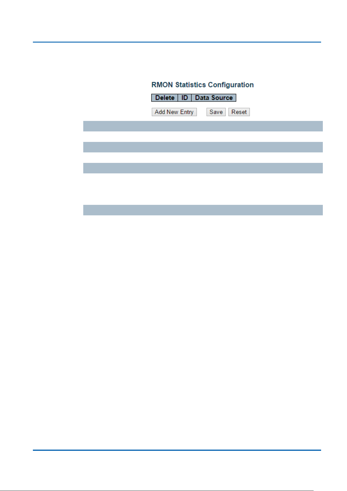
Chapter 3: Featuring Configuration – Web UI
Featuring Configuration – Web UI
RMON Statistics Configuration
Configure RMON Statistics table on this page. The entry index key is ID.
Delete
Check to delete the entry. It will be deleted during the next save.
ID
Indicates the index of the entry. The range is from 1 to 65535.
Data Source
Indicates the port ID which wants to be monitored. If in stacking switch, the value
must add 1000*(switch ID-1), for example, if the port is switch 3 port 5, the value is
2005
Buttons
Add new entry: Click to add a new community entry
Save: Click to save changes
Reset: Click to undo any changes made locally and revert to previously saved
values
NGSM48T2 User Manual | 62

Chapter 3: Featuring Configuration – Web UI
Featuring Configuration – Web UI
RMON History Configuration
Configure RMON History table on this page. The entry index key is ID
Delete
Check to delete the entry. It will be deleted during the next save.
ID
Indicates the index of the entry. The range is from 1 to 65535.
Data Source
Indicates the port ID which wants to be monitored. If in stacking switch, the value
must add 1000*(switch ID-1), for example, if the port is switch 3 port 5, the value is
2005.
Interval
Indicates the interval in seconds for sampling the history statistics data. The range is
from 1 to 3600, default value is 1800 seconds.
Buckets
Indicates the maximum data entries associated this History control entry stored in
RMON. The range is from 1 to 3600, default value is 50.
Buckets Granted
The number of data shall be saved in the RMON.
Buttons
Add new entry: Click to add a new community entry.
Save: Click to save changes.
Reset: Click to undo any changes made locally and revert to previously saved
values.
NGSM48T2 User Manual | 63

Chapter 3: Featuring Configuration – Web UI
Featuring Configuration – Web UI
RMON Alarm Configuration
Configure RMON Alarm table on this page. The entry index key is ID.
Delete
Check to delete the entry. It will be deleted during the next save.
ID
Indicates the index of the entry. The range is from 1 to 65535.
Interval
Indicates the interval in seconds for sampling and comparing the rising and falling
threshold. The range is from 1 to 2^31-1.
Variable
Indicates the particular variable to be sampled, the possible variables are:
InOctets:The total number of octets received on the interface, including framing
characters.
InUcastPkts:The number of uni-cast packets delivered to a higher-layer protocol.
InNUcastPkts: The number of broad-cast and multi-cast packets delivered to a
higher-layer protocol.
InDiscards: The number of inbound packets that are discarded even the packets
are normal.
InErrors: The number of inbound packets that contained errors preventing them
from being deliverable to a higher-layer protocol.
InUnknownProtos: The number of the inbound packets that were discarded
because of the unknown or un-support protocol.
OutOctets: The number of octets transmitted out of the interface , including framing
characters.
OutUcastPkts: The number of uni-cast packets that request to transmit.
OutNUcastPkts: The number of broad-cast and multi-cast packets that request to
transmit.
OutDiscards: The number of outbound packets that are discarded event the
packets is normal.
OutErrors: The number of outbound packets that could not be transmitted because
of errors.
OutQlen: The length of the output packet queue (in packets).
NGSM48T2 User Manual | 64

Chapter 3: Featuring Configuration – Web UI
Featuring Configuration – Web UI
Sample Type
The method of sampling the selected variable and calculating the value to be
compared against the thresholds, possible sample types are:
Absolute: Get the sample directly.
Delta: Calculate the difference between samples (default).
Value
The value of the statistic during the last sampling period.
Startup Alarm
The method of sampling the selected variable and calculating the value to be
compared against the thresholds, possible sample types are:
Rising Trigger alarm when the first value is larger than the rising threshold.
Falling Trigger alarm when the first value is less than the falling threshold.
RisingOrFalling Trigger alarm when the first value is larger than the rising threshold
or less than the falling threshold (default).
Rising Threshold
Rising threshold value (-2147483648-2147483647).
Rising Index
Rising event index (1-65535).
Falling Threshold
Falling threshold value (-2147483648-2147483647)
Falling Index
Falling event index (1-65535).
Buttons
Add new entry: Click to add a new community entry.
Save: Click to save changes.
Reset: Click to undo any changes made locally and revert to previously saved
values.
NGSM48T2 User Manual | 65

Chapter 3: Featuring Configuration – Web UI
Featuring Configuration – Web UI
RMON Event Configuration
Configure RMON Event table on this page. The entry index key is ID.
Delete
Check to delete the entry. It will be deleted during the next save.
ID
Indicates the index of the entry. The range is from 1 to 65535.
Desc
Indicates this event, the string length is from 0 to 127, default is a null string.
Type
Indicates the notification of the event, the posible types are:
None: The total number of octets received on the interface, including framing
characters.
Log: The number of uni-cast packets delivered to a higher-layer protocol.
Snmptrap: The number of broad-cast and multi-cast packets delivered to a
higher-layer protocol.
Logandtrap: The number of inbound packets that are discarded even the packets
are normal.
Community
Specify the community when trap is sent, the string lengh is from 0 to 127, default is
"public".
Event Last Time
Indicates the value of sysUp Time at the time this event entry last generated an
event.
Buttons
Add new entry: Click to add a new community entry.
Save: Click to save changes.
Reset: Click to undo any changes made locally and revert to previously saved
values.
NGSM48T2 User Manual | 66

Chapter 3: Featuring Configuration – Web UI
Featuring Configuration – Web UI
Security /Network
Port Security Limit Control Configuration
This page allows you to configure the Port Security Limit Control system and port
settings.
Limit Control allows for limiting the number of users on a given port. A user is
identified by a MAC address and VLAN ID. If Limit Control is enabled on a port, the
limit specifies the maximum number of users on the port. If this number is exceeded,
an action is taken. The action can be one of the four different actions as described
below.
The Limit Control module utilizes a lower-layer module, Port Security module, which
manages MAC addresses learnt on the port.
The Limit Control configuration consists of two sections, a system- and a port-wide.
NGSM48T2 User Manual | 67

Chapter 3: Featuring Configuration – Web UI
Featuring Configuration – Web UI
System Configuration
Mode
Indicates if Limit Control is globally enabled or disabled on the switch. If globally
disabled, other modules may still use the underlying functionality, but limit checks
and corresponding actions are disabled.
Aging Enabled
If checked, secured MAC addresses are subject to aging as discussed under Aging
Period.
Aging Period
If Aging Period is checked, then the aging period is controlled with this input. If other
modules are using the underlying port security for securing MAC addresses, they
may have other requirements to the aging period. The underlying port security will
use the shorter requested aging period of all modules that use the functionality.
The Aging Period can be set to a number between 10 and 10,000,000 seconds.
To understand why aging may be desired, consider the following scenario: Suppose
an end-host is connected to a 3rd party switch or hub, which in turn is connected to a
port on this switch on which Limit Control is enabled. The end-host will be allowed to
forward if the limit is not exceeded. Now suppose that the end-host logs off or
powers down. If it wasn't for aging, the end-host would still take up resources on this
switch and will be allowed to forward. To overcome this situation, enable aging. With
aging enabled, a timer is started once the end-host gets secured. When the timer
expires, the switch starts looking for frames from the end-host, and if such frames
are not seen within the next Aging Period, the end-host is assumed to be
disconnected, and the corresponding resources are freed on the switch.
NGSM48T2 User Manual | 68

Chapter 3: Featuring Configuration – Web UI
Featuring Configuration – Web UI
Port Configuration
The table allows you to configure the Port Configuration parameters, which are:
Port
The port number to which the configuration below applies.
Mode
Controls whether Limit Control is enabled on this port. Both this and the Global
Mode must be set to Enabled for Limit Control to be in effect. Notice that other
modules may still use the underlying port security features without enabling Limit
Control on a given port.
Limit
The maximum number of MAC addresses that can be secured on this port. This
number cannot exceed 1024. If the limit is exceeded, the corresponding action is
taken.
The switch is "born" with a total number of MAC addresses from which all ports draw
whenever a new MAC address is seen on a Port Security-enabled port. Since all
ports draw from the same pool, it may happen that a configured maximum cannot be
granted, if the remaining ports have already used all available MAC addresses.
Action
If Limit is reached, the switch can take one of the following actions:
None: Do not allow more than Limit MAC addresses on the port, but take no further
action.
Trap: If Limit+ 1 MAC addresses is seen on the port, send an SNMP trap. If Aging is
disabled, only one SNMP trap will be sent, but with Aging enabled, new SNMP traps
will be sent every time the limit gets exceeded.
Shutdown: If Limit + 1 MAC addresses is seen on the port, shut down the port. This
implies that all secured MAC addresses will be removed from the port, and no new
address will be learned. Even if the link is physically disconnected and reconnected
on the port (by disconnecting the cable), the port will remain shut down. There are
three ways to re-open the port:
1) Boot the switch,
2) Disable and re-enable Limit Control on the port or the switch,
3) Click the Reopen button.
Trap & Shutdown: If Limit + 1 MAC addresses is seen on the port, both the "Trap"
and the "Shutdown" actions described above will be taken.
NGSM48T2 User Manual | 69

Chapter 3: Featuring Configuration – Web UI
Featuring Configuration – Web UI
State
This column shows the current state of the port as seen from the Limit Control's
point of view. The state takes one of four values:
Disabled: Limit Control is either globally disabled or disabled on the port.
Ready: The limit is not yet reached. This can be shown for all actions.
Limit Reached: Indicates that the limit is reached on this port. This state can only be
shown if Action is set to None or Trap.
Shutdown: Indicates that the port is shut down by the Limit Control module. This
state can only be shown if Action is set to Shutdown or Trap & Shutdown.
Re-open Button
If a port is shutdown by this module, you may reopen it by clicking this button, which
will only be enabled if this is the case. For other methods, refer to Shutdown in the
Action section.
Note that clicking the reopen button causes the page to be refreshed, so
non-committed changes will be lost.
Buttons
Refresh: Click to refresh the page. Note that non-committed changes will be lost.
Save: Click to save changes.
Reset: Click to undo any changes made locally and revert to previously saved
values.
NGSM48T2 User Manual | 70

Chapter 3: Featuring Configuration – Web UI
Featuring Configuration – Web UI
Security / Network / Network Access Server Configuration
This page allows you to configure the IEEE802.1X and MAC-based authentication
system and port settings.
The IEEE 802.1X standard defines a port-based access control procedure that
prevents unauthorized access to a network by requiring users to first submit
credentials for authentication. One or more central servers, the backend servers,
determine whether the user is allowed access to the network. These backend
(RADIUS) servers are configured on the "Configuration→Security→AAA" page.The
IEEE802.1X standard defines port-based operation, but non-standard variants
overcome security limitations as shall be explored below.
MAC-based authentication allows for authentication of more than one user on the
same port, and doesn't require the user to have special 802.1X supplicant software
installed on his system. The switch uses the user's MAC address to authenticate
against the backend server. Intruders can create counterfeit MAC addresses, which
makes MAC-based authentication less secure than 802.1X authentication.
The NAS configuration consists of two sections, a system- and a port-wide.
NGSM48T2 User Manual | 71

Chapter 3: Featuring Configuration – Web UI
Featuring Configuration – Web UI
System Configuration
Mode
Indicates if NAS is globally enabled or disabled on the switch. If globally disabled, all
ports are allowed forwarding of frames.
Reauthentication Enabled
If checked, successfully authenticated supplicants/clients are reauthenticated after
the interval specified by the Reauthentication Period. Reauthentication for
802.1X-enabled ports can be used to detect if a new device is plugged into a switch
port or if a supplicant is no longer attached.
For MAC-based ports, reauthentication is only useful if the RADIUS server
configuration has changed. It does not involve communication between the switch
and the client, and therefore doesn't imply that a client is still present on a port (see
Aging Period below).
Reauthentication Period
Determines the period, in seconds, after which a connected client must be
reauthenticated. This is only active if the Reauthentication Enabled checkbox is
checked. Valid values are in the range 1 to 3600 seconds.
EAPOL Timeout
Determines the time for retransmission of Request Identity EAPOL frames.
Valid values are in the range 1 to 65535 seconds. This has no effect for MAC-based
ports.
Aging Period
This setting applies to the following modes, i.e. modes using the Port Security
functionality to secure MAC addresses:
Single 802.1X
Multi 802.1X
MAC-Based Auth.
When the NAS module uses the Port Security module to secure MAC addresses,
the Port Security module needs to check for activity on the MAC address in question
at regular intervals and free resources if no activity is seen within a given period of
time. This parameter controls exactly this period and can be set to a number
between 10 and 1000000 seconds.
If reauthentication is enabled and the port is in an 802.1X-based mode, this is not so
critical, since supplicants that are no longer attached to the port will get removed
upon the next reauthentication, which will fail. But if reauthentication is not enabled,
the only way to free resources is by aging the entries.
NGSM48T2 User Manual | 72

Chapter 3: Featuring Configuration – Web UI
Featuring Configuration – Web UI
For ports in MAC-based Auth. mode, reauthentication doesn't cause direct
communication between the switch and the client, so this will not detect whether the
client is still attached or not, and the only way to free any resources is to age the
entry.
Hold Time
This setting applies to the following modes, i.e. modes using the Port Security
functionality to secure MAC addresses:
Single 802.1X
Multi 802.1X
MAC-Based Auth.
If a client is denied access - either because the RADIUS server denies the client
access or because the RADIUS server request times out (according to the timeout
specified on the "Configuration→Security→AAA" page) - the client is put on hold in
the Unauthorized state. The hold timer does not count during an on-going
authentication.
In MAC-based Auth. mode, the switch will ignore new frames coming from the client
during the hold time.
The Hold Time can be set to a number between 10 and 1000000 seconds.
RADIUS-Assigned QoS Enabled
RADIUS-assigned QoS provides a means to centrally control the traffic class to
which traffic coming from a successfully authenticated supplicant is assigned on the
switch. The RADIUS server must be configured to transmit special RADIUS
attributes to take advantage of this feature (see RADIUS-Assigned QoS Enabled
below for a detailed description).
The "RADIUS-Assigned QoS Enabled" checkbox provides a quick way to globally
enable/disable RADIUS-server assigned QoS Class functionality. When checked,
the individual ports' ditto setting determine whether RADIUS-assigned QoS Class is
enabled on that port. When unchecked, RADIUS-server assigned QoS Class is
disabled on all ports.
RADIUS-Assigned VLAN Enabled
RADIUS-assigned VLAN provides a means to centrally control the VLAN on which a
successfully authenticated supplicant is placed on the switch. Incoming traffic will be
classified to and switched on the RADIUS-assigned VLAN. The RADIUS server
must be configured to transmit special RADIUS attributes to take advantage of this
feature (see RADIUS-Assigned VLAN Enabled below for a detailed description).
NGSM48T2 User Manual | 73

Chapter 3: Featuring Configuration – Web UI
Featuring Configuration – Web UI
The "RADIUS-Assigned VLAN Enabled" checkbox provides a quick way to globally
enable/disable RADIUS-server assigned VLAN functionality. When checked, the
individual ports' ditto setting determine whether RADIUS-assigned VLAN is enabled
on that port. When unchecked, RADIUS-server assigned VLAN is disabled on all
ports.
Guest VLAN Enabled
A Guest VLAN is a special VLAN - typically with limited network access - on which
802.1X-unaware clients are placed after a network administrator-defined timeout.
The switch follows a set of rules for entering and leaving the Guest VLAN as listed
below.
The "Guest VLAN Enabled" checkbox provides a quick way to globally
enable/disable Guest VLAN functionality. When checked, the individual ports' ditto
setting determines whether the port can be moved into Guest VLAN. When
unchecked, the ability to move to the Guest VLAN is disabled on all ports.
Guest VLAN ID
This is the value that a port's Port VLAN ID is set to if a port is moved into the Guest
VLAN. It is only changeable if the Guest VLAN option is globally enabled.
Valid values are in the range [1; 4095].
Max. Reauth. Count
The number of times the switch transmits an EAPOL Request Identity frame without
response before considering entering the Guest VLAN is adjusted with this setting.
The value can only be changed if the Guest VLAN option is globally enabled.
Valid values are in the range [1; 255].
Allow Guest VLAN if EAPOL Seen
The switch remembers if an EAPOL frame has been received on the port for the
life-time of the port. Once the switch considers whether to enter the Guest VLAN, it
will first check if this option is enabled or disabled. If disabled (unchecked; default),
the switch will only enter the Guest VLAN if an EAPOL frame has not been received
on the port for the life-time of the port. If enabled (checked), the switch will consider
entering the Guest VLAN even if an EAPOL frame has been received on the port for
the life-time of the port.
The value can only be changed if the Guest VLAN option is globally enabled.
NGSM48T2 User Manual | 74

Chapter 3: Featuring Configuration – Web UI
Featuring Configuration – Web UI
Port Configuration
The table has number of columns which allows you to configure the port mode
based on IEEE 802.1X standard. Select the port and configure the settings.
Port
The port number for which the configuration below applies.
Admin State
If NAS is globally enabled, this selection controls the port's authentication mode.
The following modes are available:
Force Authorized
In this mode, the switch will send one EAPOL Success frame when the port link
comes up, and any client on the port will be allowed network access without
authentication.
Force Unauthorized
In this mode, the switch will send one EAPOL Failure frame when the port link
comes up, and any client on the port will be disallowed network access.
Port-based 802.1X
In the 802.1X-world, the user is called the supplicant, the switch is the authenticator,
and the RADIUS server is the authentication server. The authenticator acts as the
man-in-the-middle, forwarding requests and responses between the supplicant and
the authentication server. Frames sent between the supplicant and the switch are
special 802.1X frames, known as EAPOL (EAP Over LANs) frames.
EAPOL frames encapsulate EAP PDUs (RFC3748). Frames sent between the
switch and the RADIUS server are RADIUS packets. RADIUS packets also
encapsulate EAP PDUs together with other attributes like the switch's IP address,
name, and the supplicant's port number on the switch. EAP is very flexible, in that it
allows for different authentication methods, like MD5-CHALLENGE, PEAP, and TLS.
The important thing is that the authenticator (the switch) doesn't need to know which
authentication method the supplicant and the authentication server are using, or
how many information exchange frames are needed for a particular method. The
NGSM48T2 User Manual | 75

Chapter 3: Featuring Configuration – Web UI
Featuring Configuration – Web UI
switch simply encapsulates the EAP part of the frame into the relevant type (EAPOL
or RADIUS) and forwards it.
When authentication is complete, the RADIUS server sends a special packet
containing a success or failure indication. Besides forwarding this decision to the
supplicant, the switch uses it to open up or block traffic on the switch port connected
to the supplicant.
Note: Suppose two backend servers are enabled and that the server timeout is
configured to X seconds (using the AAA configuration page), and suppose that the
first server in the list is currently down (but not considered dead). Now, if the
supplicant retransmits EAPOL Start frames at a rate faster than X seconds, then it
will never get authenticated, because the switch will cancel on-going backend
authentication server requests whenever it receives a new EAPOL Start frame from
the supplicant. And since the server hasn't yet failed (because the X seconds
haven't expired), the same server will be contacted upon the next backend
authentication server request from the switch. This scenario will loop forever.
Therefore, the server timeout should be smaller than the supplicant's EAPOL Start
frame retransmission rate.
Single 802.1X
In port-based 802.1X authentication, once a supplicant is successfully authenticated
on a port, the whole port is opened for network traffic. This allows other clients
connected to the port (for instance through a hub) to piggy-back on the successfully
authenticated client and get network access even though they really aren't
authenticated. To overcome this security breach, use the Single 802.1X variant.
Single 802.1X is really not an IEEE standard, but features many of the same
characteristics as does port-based 802.1X. In Single 802.1X, at most one supplicant
can get authenticated on the port at a time. Normal EAPOL frames are used in the
communication between the supplicant and the switch. If more than one supplicant
is connected to a port, the one that comes first when the port's link comes up will be
the first one considered. If that supplicant doesn't provide valid credentials within a
certain amount of time, another supplicant will get a chance. Once a supplicant is
successfully authenticated, only that supplicant will be allowed access. This is the
most secure of all the supported modes. In this mode, the Port Security module is
used to secure a supplicant's MAC address once successfully authenticated.
Multi 802.1X
Multi 802.1X is - like Single 802.1X - not an IEEE standard, but a variant that
NGSM48T2 User Manual | 76

Chapter 3: Featuring Configuration – Web UI
Featuring Configuration – Web UI
features many of the same characteristics.In Multi 802.1X, one or more supplicants
can get authenticated on the same port at the same time. Each supplicant is
authenticated individually and secured in the MAC table using the Port Security
module.
In Multi 802.1X it is not possible to use the multicast BPDU MAC address as
destination MAC address for EAPOL frames sent from the switch towards the
supplicant, since that would cause all supplicants attached to the port to reply to
requests sent from the switch. Instead, the switch uses the supplicant's MAC
address, which is obtained from the first EAPOL Start or EAPOL Response Identity
frame sent by the supplicant. An exception to this is when no supplicants are
attached. In this case, the switch sends EAPOL Request Identity frames using the
BPDU multicast MAC address as destination - to wake up any supplicants that might
be on the port.
The maximum number of supplicants that can be attached to a port can be limited
using the Port Security Limit Control functionality.MAC-based Auth.
Unlike port-based 802.1X, MAC-based authentication is not a standard, but merely
a best-practices method adopted by the industry. In MAC-based authentication,
users are called clients, and the switch acts as the supplicant on behalf of clients.
The initial frame (any kind of frame) sent by a client is snooped by the switch, which
in turn uses the client's MAC address as both username and password in the
subsequent EAP exchange with the RADIUS server. The 6-byte MAC address is
converted to a string on the following form "xx-xx-xx-xx-xx-xx", that is, a dash (-) is
used as separator between the lower-cased hexadecimal digits. The switch only
supports the MD5-Challenge authentication method, so the RADIUS server must be
configured accordingly.
When authentication is complete, the RADIUS server sends a success or failure
indication, which in turn causes the switch to open up or block traffic for that
particular client, using the Port-Security module. Only then will frames from the client
be forwarded on the switch. There are no EAPOL frames involved in this
authentication, and therefore, MAC-based Authentication has nothing to do with the
802.1X standard.
The advantage of MAC-based authentication over 802.1X-based authentication is
that the clients don't need special supplicant software to authenticate. The
disadvantage is that MAC addresses can be spoofed by malicious users -
NGSM48T2 User Manual | 77

Chapter 3: Featuring Configuration – Web UI
Featuring Configuration – Web UI
equipment whose MAC address is a valid RADIUS user can be used by anyone.
Also, only the MD5-Challenge method is supported. The maximum number of clients
that can be attached to a port can be limited using the Port Security Limit Control
functionality.
RADIUS-Assigned QoS Enabled
When RADIUS-Assigned QoS is both globally enabled and enabled (checked) on a
given port, the switch reacts to QoS Class information carried in the RADIUS
Access-Accept packet transmitted by the RADIUS server when a supplicant is
successfully authenticated. If present and valid, traffic received on the supplicant's
port will be classified to the given QoS Class. If (re-)authentication fails or the
RADIUS Access-Accept packet no longer carries a QoS Class or it's invalid, or the
supplicant is otherwise no longer present on the port, the port's QoS Class is
immediately reverted to the original QoS Class (which may be changed by the
administrator in the meanwhile without affecting the RADIUS-assigned).
This option is only available for single-client modes, i.e.
Port-based 802.1X
Single 802.1X0
RADIUS attributes used in identifying a QoS Class:
The User-Priority-Table attribute defined in RFC4675 forms the basis for identifying
the QoS Class in an Access-Accept packet.
Only the first occurrence of the attribute in the packet will be considered, and to be
valid, it must follow this rule:
All 8 octets in the attribute's value must be identical and consist of ASCII
characters in the range '0' - '3', which translates into the desired QoS Class in
the range [0; 3].
NGSM48T2 User Manual | 78

Chapter 3: Featuring Configuration – Web UI
Featuring Configuration – Web UI
RADIUS-Assigned VLAN Enabled
When RADIUS-Assigned VLAN is both globally enabled and enabled (checked) for
a given port, the switch reacts to VLAN ID information carried in the RADIUS
Access-Accept packet transmitted by the RADIUS server when a supplicant is
successfully authenticated. If present and valid, the port's Port VLAN ID will be
changed to this VLAN ID, the port will be set to be a member of that VLAN ID, and
the port will be forced into VLAN unaware mode. Once assigned, all traffic arriving
on the port will be classified and switched on the RADIUS-assigned VLAN ID.
If (re-)authentication fails or the RADIUS Access-Accept packet no longer carries a
VLAN ID or it's invalid, or the supplicant is otherwise no longer present on the port,
the port's VLAN ID is immediately reverted to the original VLAN ID (which may be
changed by the administrator in the meanwhile without affecting the
RADIUS-assigned).
This option is only available for single-client modes, i.e.
Port-based 802.1X
Single 802.1X
For trouble-shooting VLAN assignments, use the "Monitor→VLANs→VLAN
Membership and VLAN Port" pages. These pages show which modules have
(temporarily) overridden the current Port VLAN configuration.
RADIUS attributes used in identifying a VLAN ID:
RFC2868 and RFC3580 form the basis for the attributes used in identifying a VLAN
ID in an Access-Accept packet. The following criteria are used:
The Tunnel-Medium-Type, Tunnel-Type, and Tunnel-Private-Group-IDattributes
must all be present at least once in the Access-Accept packet.
The switch looks for the first set of these attributes that have the same Tag
value and fulfil the following requirements (if Tag == 0 is used, the
Tunnel-Private-Group-IDdoes not need to include a Tag):
Value of Tunnel-Medium-Type must be set to "IEEE-802" (ordinal 6).
Value of Tunnel-Type must be set to "VLAN" (ordinal 13).
Value of Tunnel-Private-Group-ID must be a string of ASCII chars in the
range '0' - '9', which is interpreted as a decimal string representing the
VLAN ID. Leading '0's are discarded. The final value must be in the range
[1; 4095].
NGSM48T2 User Manual | 79

Chapter 3: Featuring Configuration – Web UI
Featuring Configuration – Web UI
Guest VLAN Enabled
When Guest VLAN is both globally enabled and enabled (checked) for a given port,
the switch considers moving the port into the Guest VLAN according to the rules
outlined below.
This option is only available for EAPOL-based modes, i.e.:
Port-based 802.1X
Single 802.1X
Multi 802.1X
For trouble-shooting VLAN assignments, use the "Monitor→VLANs→VLAN
Membership and VLAN Port" pages. These pages show which modules have
(temporarily) overridden the current Port VLAN configuration.
Guest VLAN Operation:
When a Guest VLAN enabled port's link comes up, the switch starts transmitting
EAPOL Request Identity frames. If the number of transmissions of such frames
exceeds Max,. Reauth., Count and no EAPOL frames have been received in the
meanwhile, the switch considers entering the Guest VLAN. The interval between
transmission of EAPOL Request Identity frames is configured with EAPOL Timeout.
If
Allow guest VLAN if EAPOL Seen is enabled, the port will now be placed in the
Guest VLAN. If disabled, the switch will first check its history to see if an EAPOL
frame has previously been received on the port (this history is cleared if the port link
goes down or the port's Admin State is changed), and if not, the port will be placed in
the Guest VLAN. Otherwise it will not move to the Guest VLAN, but continue
transmitting EAPOL Request Identity frames at the rate given by EAPOL Timeout.
Once in the Guest VLAN, the port is considered authenticated, and all attached
clients on the port are allowed access on this VLAN. The switch will not transmit an
EAPOL Success frame when entering the Guest VLAN.
While in the Guest VLAN, the switch monitors the link for EAPOL frames, and if one
such frame is received, the switch immediately takes the port out of the Guest VLAN
and starts authenticating the supplicant according to the port mode. If an EAPOL
frame is received, the port will never be able to go back into the Guest VLAN if the
"Allow Guest VLAN if EAPOL Seen" is disabled.
NGSM48T2 User Manual | 80

Chapter 3: Featuring Configuration – Web UI
Featuring Configuration – Web UI
Port State
The current state of the port. It can undertake one of the following values:
Globally Disabled: NAS is globally disabled.
Link Down: NAS is globally enabled, but there is no link on the port.
Authorized: The port is in Force Authorized or a single-supplicant mode and the
supplicant is authorized.
Unauthorized: The port is in Force Unauthorized or a single-supplicant mode and
the supplicant is not successfully authorized by the RADIUS server.
X Auth/Y Unauth: The port is in a multi-supplicant mode. Currently X clients are
authorized and Y are unauthorized.
Restart
Two buttons are available for each row. The buttons are only enabled when
authentication is globally enabled and the port's Admin State is in an EAPOL-based
or MAC-based mode.
Clicking these buttons will not cause settings changed on the page to take effect.
Reauthenticate: Schedules a reauthentication whenever the quiet-period of the port
runs out(EAPOL-based authentication).For MAC-based authentication,
reauthentication will be attempted immediately.
The button only has effect for successfully authenticated clients on the port and will
not cause the clients to get temporarily unauthorized.
Reinitialize: Forces a reinitialization of the clients on the port and thereby a
reauthentication immediately. The clients will transfer to the unauthorized state while
the reauthentication is in progress.
Buttons
Refresh: Click to refresh the page.
Save: Click to save changes.
Reset: Click to undo any changes made locally and revert to previously saved
values.
NGSM48T2 User Manual | 81

Chapter 3: Featuring Configuration – Web UI
Featuring Configuration – Web UI
Security / Network / Access Control List Configuration
Configure the ACL parameters (ACE) of each switch port. These parameters will
affect frames received on a port unless the frame matches a specific ACE.
The settings relate to the currently selected stack unit, as reflected by the page
header.
Port
The logical port for the settings contained in the same row.
Policy ID
Select the policy to apply to this port. The allowed values are 0 through 255. The
default value is 0.
Action
Select whether forwarding is permitted ("Permit") or denied ("Deny"). The default
value is "Permit".
Rate Limiter ID
Select which rate limiter to apply on this port. The allowed values are Disabled or the
values 1 through 16. The default value is "Disabled".
SelectSelectDisabledPort Copy
Select which port frames are copied on. The allowed values are Disabled or a
specific port number. The default value is "Disabled".
Mirror
Specify the mirror operation of this port. The allowed values are:
Enabled: Frames received on the port are mirrored.
Disabled: Frames received on the port are not mirrored.
The default value is "Disabled".
NGSM48T2 User Manual | 82

Chapter 3: Featuring Configuration – Web UI
Featuring Configuration – Web UI
Logging
Specify the logging operation of this port. The allowed values are:
Enabled: Frames received on the port are stored in the System Log.
Disabled: Frames received on the port are not logged.
The default value is "Disabled". Please note that the System Log memory size and
logging rate is limited.
Shutdown
Specify the port shut down operation of this port. The allowed values are:
Enabled: If a frame is received on the port, the port will be disabled.
Disabled: Port shut down is disabled.
The default value is "Disabled".
Counter
Counts the number of frames that match this ACE.
Buttons
Save: Click to save changes.
Reset: Click to undo any changes made locally and revert to previously saved
values.
Refresh: Click to refresh the page. Any changes made locally will be undone..
Clear: Click to clear the counter
NGSM48T2 User Manual | 83

Chapter 3: Featuring Configuration – Web UI
Featuring Configuration – Web UI
ACL Rate Limiters Configuration
Configure the rate limiter for the ACL of the switch
Rate Limiter ID
The rate limiter ID for the settings contained in the same row.
Rate
The allowed values are: 0-3276700 in pps
Or 0,100,200,300,…,1000000 in kbps.
Unit
Specify the rate unit. The allowed values are:
pps: packets per second.
kbps: Kbits per second.
Buttons
Save: Click to save changes.
Reset: Click to undo any changes made locally and revert to previously saved
values.
NGSM48T2 User Manual | 84

Chapter 3: Featuring Configuration – Web UI
Featuring Configuration – Web UI
Access Control List Configuration
This page shows the Access Control List (ACL), which is made up of the ACEs
defined on this switch. Each row describes the ACE that is defined. The maximum
number of ACEs is 256 on each switch.
Click on the lowest plus sign to add a new ACE to the list. The reserved ACEs used
for internal protocol, cannot be edited or deleted, the order sequence cannot be
changed and the priority is highest.
Ingress Port
Indicates the ingress port of the ACE. Possible values are:
All: The ACE will match all ingress port.
Port: The ACE will match a specific ingress port.
Policy / Bitmask
Indicates the policy number and bitmask of the ACE.
Frame Type
Indicates the frame type of the ACE. Possible values are:
Any: The ACE will match any frame type.
EType: The ACE will match Ethernet Type frames. Note that an Ethernet Type
based ACE will not get matched by IP and ARP frames.
ARP: The ACE will match ARP/RARP frames.
IPv4: The ACE will match all IPv4 frames.
IPv4/ICMP: The ACE will match IPv4 frames with ICMP protocol.
IPv4/UDP: The ACE will match IPv4 frames with UDP protocol.
IPv4/TCP: The ACE will match IPv4 frames with TCP protocol.
IPv4/Other: The ACE will match IPv4 frames, which are not ICMP/UDP/TCP.
IPv6: The ACE will match all IPv6 standard frames.
Action
Indicates the forwarding action of the ACE.
Permit: Frames matching the ACE may be forwarded and learned.
Deny: Frames matching the ACE are dropped.
Rate Limiter
Indicates the rate limiter number of the ACE. The allowed range is 1 to 16. When
Disabled is displayed, the rate limiter operation is disabled.
NGSM48T2 User Manual | 85

Chapter 3: Featuring Configuration – Web UI
Featuring Configuration – Web UI
Port Copy
Indicates the port copy operation of the ACE. Frames matching the ACE are copied
to the port number. The allowed values are Disabled or a specific port number.
When Disabled is displayed, the port copy operation is disabled.
Mirror
Specify the mirror operation of this port. Frames matching the ACE are mirrored to
the destination mirror port. The allowed values are:
Enabled: Frames received on the port are mirrored.
Disabled: Frames received on the port are not mirrored.
The default value is "Disabled".
Counter
The counter indicates the number of times the ACE was hit by a frame.
Modification Buttons
You can modify each ACE (Access Control Entry) in the table using the following
buttons:
: Inserts a new ACE before the current row.
: Edits the ACE row.
: Moves the ACE up the list.
: Moves the ACE down the list.
: Deletes the ACE.
: The lowest plus sign adds a new entry at the bottom of the ACE listings.
Buttons
Auto-refresh: Check this box to refresh the page automatically. Automatic refresh
occurs at regular intervals.
Refresh: Click to refresh the page. Note that non-committed changes will be lost.
Clear: Click to clear the counter
Remove All: Click to remove all ACEs
NGSM48T2 User Manual | 86

Chapter 3: Featuring Configuration – Web UI
Featuring Configuration – Web UI
ACE Configuration
Configure an ACE (Access Control Entry) on this page.
An ACE consists of several parameters. These parameters vary according to the
frame type that you select. First select the ingress port for the ACE, and then select
the frame type. Different parameter options are displayed depending on the frame
type selected.
A frame that hits this ACE matches the configuration that is defined here.
Ingress Port
Select the ingress port for which this ACE applies.
All: The ACE applies to all port.
Port n: The ACE applies to this port number, where n is the number of the switch
port. You can select one port or select multiple ports for the entry.
Policy Filter
Specify the policy number filter for this ACE. The policy ID should be the same when
you want apply it to the ACL or Port.
Any: No policy filter is specified. (policy filter status is "don't-care".)
Specific: If you want to filter a specific policy with this ACE, choose this value. Two
field for entering an policy value and bitmask appears.
Policy Value
When "Specific" is selected for the policy filter, you can enter a specific policy value.
The allowed range is 0 to 255.
Policy Bitmask
When "Specific" is selected for the policy filter, you can enter a specific policy
bitmask. The allowed range is 0x0 to 0xff.
NGSM48T2 User Manual | 87

Chapter 3: Featuring Configuration – Web UI
Featuring Configuration – Web UI
Select the switch to which this ACE applies. This parameter is reserved to the
Stacking model. If the switch doesn't support stacking, the parameter will not display
here.
Any: The ACE applies to any port.
Switch n: The ACE applies to this switch number, where n is the number of the
switch.
Frame Type
Select the frame type for this ACE. These frame types are mutually exclusive.
Any: Any frame can match this ACE.
Ethernet Type: Only Ethernet Type frames can match this ACE. The IEEE 802.3
describes the value of Length/Type Field specifications to be greater than or equal to
1536 decimal (equal to 0600 hexadecimal).
ARP: Only ARP frames can match this ACE. Notice the ARP frames won't match the
ACE with ethernet type.
IPv4: Only IPv4 frames can match this ACE. Notice the IPv4 frames won't match the
ACE with ethernet type.
IPv6: Only IPv6 frames can match this ACE. Notice the IPv6 frames won't match the
ACE with ehternet type.
Action
Specify the action to take with a frame that hits this ACE.
Permit: The frame that hits this ACE is granted permission for the ACE operation.
Deny: The frame that hits this ACE is dropped.
Rate Limiter
Specify the rate limiter in number of base units. The allowed range is 1 to 16.
Disabled indicates that the rate limiter operation is disabled.
SelectSelectPort Copy
Frames that hit the ACE are copied to the port number specified here. The allowed
range is the same as the switch port number range. Disabled indicates that the port
copy operation is disabled.
NGSM48T2 User Manual | 88

Chapter 3: Featuring Configuration – Web UI
Featuring Configuration – Web UI
Mirror
Specify the mirror operation of this port. Frames matching the ACE are mirrored to
the destination mirror port. The allowed values are:
Enabled: Frames received on the port are mirrored.
Disabled: Frames received on the port are not mirrored.
The default value is "Disabled".
Logging
Specify the logging operation of the ACE. The allowed values are:
Enabled: Frames matching the ACE are stored in the System Log.
Disabled: Frames matching the ACE are not logged.
Please note that the System Log memory size and logging rate is limited.
Shutdown
Specify the port shut down operation of the ACE. The allowed values are:
Enabled: If a frame matches the ACE, the ingress port will be disabled.
Disabled: Port shut down is disabled for the ACE.
Counter
The counter indicates the number of times the ACE was hit by a frame.
MAC Parameters
SMAC Filter
(Only displayed when the frame type is Ethernet Type or ARP.)
Specify the source MAC filter for this ACE.
Any: No SMAC filter is specified. (SMAC filter status is "don't-care".)
Specific: If you want to filter a specific source MAC address with this ACE, choose
this value. A field for entering an SMAC value appears.
SMAC Value
When "Specific" is selected for the SMAC filter, you can enter a specific source MAC
address. The legal format is "xx-xx-xx-xx-xx-xx". A frame that hits this ACE matches
this SMAC value.
DMAC Filter
Specify the destination MAC filter for this ACE.
Any: No DMAC filter is specified. (DMAC filter status is "don't-care".)
MC: Frame must be multicast.
BC: Frame must be broadcast.
UC: Frame must be unicast.
Specific: If you want to filter a specific destination MAC address with this ACE,
choose this value. A field for entering a DMAC value appears.
NGSM48T2 User Manual | 89

Chapter 3: Featuring Configuration – Web UI
Featuring Configuration – Web UI
DMAC Value
When "Specific" is selected for the DMAC filter, you can enter a specific destination
MAC address. The legal format is "xx-xx-xx-xx-xx-xx". A frame that hits this ACE
matches this DMAC value.
VLAN Parameters
802.1Q Tagged
Specify whether frames can hit the action according to the 802.1Q tagged. The
allowed values are:
Any: Any value is allowed ("don't-care").
Enabled: Tagged frame only.
Disabled: Untagged frame only.
The default value is "Any".
VLAN ID Filter
Specify the VLAN ID filter for this ACE.
Any: No VLAN ID filter is specified. (VLAN ID filter status is "don't-care".)
Specific: If you want to filter a specific VLAN ID with this ACE, choose this value. A
field for entering a VLAN ID number appears.
VLAN ID
When "Specific" is selected for the VLAN ID filter, you can enter a specific VLAN ID
number. The allowed range is 1 to 4095. A frame that hits this ACE matches this
VLAN ID value.
Tag Priority
Specify the tag priority for this ACE. A frame that hits this ACE matches this tag
priority. The allowed number range is 0 to 7. The value Any means that no tag
priority is specified (tag priority is "don't-care".)
ARP Parameters
The ARP parameters can be configured when Frame Type "ARP" is selected.
ARP/RARP
Specify the available ARP/RARP opcode (OP) flag for this ACE.
Any: No ARP/RARP OP flag is specified. (OP is "don't-care".)
ARP: Frame must have ARP/RARP opcode set to ARP.
RARP: Frame must have ARP/RARP opcode set to RARP.
Other: Frame has unknown ARP/RARP Opcode flag.
Request/Reply
Specify the available ARP/RARP opcode (OP) flag for this ACE.
Any: No ARP/RARP OP flag is specified. (OP is "don't-care".)
NGSM48T2 User Manual | 90

Chapter 3: Featuring Configuration – Web UI
Featuring Configuration – Web UI
Request: Frame must have ARP Request or RARP Request OP flag set.
Reply: Frame must have ARP Reply or RARP Reply OP flag.
Sender IP Filter
Specify the sender IP filter for this ACE.
Any: No sender IP filter is specified. (Sender IP filter is "don't-care".)
Host: Sender IP filter is set to Host. Specify the sender IP address in the SIP
Address field that appears.
Network: Sender IP filter is set to Network. Specify the sender IP address and
sender IP mask in the SIP Address and SIP Mask fields that appear.
Sender IP Address
When "Host" or "Network" is selected for the sender IP filter, you can enter a specific
sender IP address in dotted decimal notation.
Sender IP Mask
When "Network" is selected for the sender IP filter, you can enter a specific sender
IP mask in dotted decimal notation.
Target IP Filter
Specify the target IP filter for this specific ACE.
Any: No target IP filter is specified. (Target IP filter is "don't-care".)
Host: Target IP filter is set to Host. Specify the target IP address in the Target IP
Address field that appears.
Network: Target IP filter is set to Network. Specify the target IP address and target
IP mask in the Target IP Address and Target IP Mask fields that appear.
Target IP Address
When "Host" or "Network" is selected for the target IP filter, you can enter a specific
target IP address in dotted decimal notation.
Target IP Mask
When "Network" is selected for the target IP filter, you can enter a specific target IP
mask in dotted decimal notation.
ARP SMAC Match
Specify whether frames can hit the action according to their sender hardware
address field (SHA) settings.
0: ARP frames where SHA is not equal to the SMAC address.
1: ARP frames where SHA is equal to the SMAC address.
Any: Any value is allowed ("don't-care").
NGSM48T2 User Manual | 91

Chapter 3: Featuring Configuration – Web UI
Featuring Configuration – Web UI
RARP DMAC Match
Specify whether frames can hit the action according to their target hardware address
field (THA) settings.
0: RARP frames where THA is not equal to the DMAC address.
1: RARP frames where THA is equal to the DMAC address.
Any: Any value is allowed ("don't-care").
IP/Ethernet Length
Specify whether frames can hit the action according to their ARP/RARP hardware
address length (HLN) and protocol address length (PLN) settings.
0: ARP/RARP frames where the HLN is not equal to Ethernet (0x06) or the (PLN) is
not equal to IPv4 (0x04).
1: ARP/RARP frames where the HLN is equal to Ethernet (0x06) and the (PLN) is
equal to IPv4 (0x04).
Any: Any value is allowed ("don't-care").
IP
Specify whether frames can hit the action according to their ARP/RARP hardware
address space (HRD) settings.
0: ARP/RARP frames where the HLD is not equal to Ethernet (1).
1: ARP/RARP frames where the HLD is equal to Ethernet (1).
Any: Any value is allowed ("don't-care").
Ethernet
Specify whether frames can hit the action according to their ARP/RARP protocol
address space (PRO) settings.
0: ARP/RARP frames where the PRO is not equal to IP (0x800).
1: ARP/RARP frames where the PRO is equal to IP (0x800).
Any: Any value is allowed ("don't-care").
NGSM48T2 User Manual | 92

Chapter 3: Featuring Configuration – Web UI
Featuring Configuration – Web UI
IP Parameters
The IP parameters can be configured when Frame Type "IPv4" is selected.
IP Protocol Filter
Specify the IP protocol filter for this ACE.
Any: No IP protocol filter is specified ("don't-care").
Specific: If you want to filter a specific IP protocol filter with this ACE, choose this
value. A field for entering an IP protocol filter appears.
ICMP: Select ICMP to filter IPv4 ICMP protocol frames. Extra fields for defining
ICMP parameters will appear. These fields are explained later in this help file.
UDP: Select UDP to filter IPv4 UDP protocol frames. Extra fields for defining UDP
parameters will appear. These fields are explained later in this help file.
TCP: Select TCP to filter IPv4 TCP protocol frames. Extra fields for defining TCP
parameters will appear. These fields are explained later in this help file.
IP Protocol Value
When "Specific" is selected for the IP protocol value, you can enter a specific value.
The allowed range is 0 to 255. A frame that hits this ACE matches this IP protocol
value.
IP TTL
Specify the Time-to-Live settings for this ACE.
zero: IPv4 frames with a Time-to-Live field greater than zero must not be able to
match this entry.
non-zero: IPv4 frames with a Time-to-Live field greater than zero must be able to
match this entry.
Any: Any value is allowed ("don't-care").
IP Fragment
Specify the fragment offset settings for this ACE. This involves the settings for the
More Fragments (MF) bit and the Fragment Offset (FRAG OFFSET) field for an IPv4
frame.
No: IPv4 frames where the MF bit is set or the FRAG OFFSET field is greater than
zero must not be able to match this entry.
Yes: IPv4 frames where the MF bit is set or the FRAG OFFSET field is greater than
zero must be able to match this entry.
Any: Any value is allowed ("don't-care").
NGSM48T2 User Manual | 93

Chapter 3: Featuring Configuration – Web UI
Featuring Configuration – Web UI
IP Option
Specify the options flag setting for this ACE.
No: IPv4 frames where the options flag is set must not be able to match this entry.
Yes: IPv4 frames where the options flag is set must be able to match this entry.
Any: Any value is allowed ("don't-care").
SIP Filter
Specify the source IP filter for this ACE.
Any: No source IP filter is specified. (Source IP filter is "don't-care".)
Host: Source IP filter is set to Host. Specify the source IP address in the SIP
Address field that appears.
Network: Source IP filter is set to Network. Specify the source IP address and
source IP mask in the SIP Address and SIP Mask fields that appear.
SIP Address
When "Host" or "Network" is selected for the source IP filter, you can enter a specific
SIP address in dotted decimal notation.
SIP Mask
When "Network" is selected for the source IP filter, you can enter a specific SIP
mask in dotted decimal notation.
DIP Filter
Specify the destination IP filter for this ACE.
Any: No destination IP filter is specified. (Destination IP filter is "don't-care".)
Host: Destination IP filter is set to Host. Specify the destination IP address in the
DIP Address field that appears.
Network: Destination IP filter is set to Network. Specify the destination IP address
and destination IP mask in the DIP Address and DIP Mask fields that appear.
DIP Address
When "Host" or "Network" is selected for the destination IP filter, you can enter a
specific DIP address in dotted decimal notation.
DIP Mask
When "Network" is selected for the destination IP filter, you can enter a specific DIP
mask in dotted decimal notation.
NGSM48T2 User Manual | 94

Chapter 3: Featuring Configuration – Web UI
Featuring Configuration – Web UI
ICMP Parameters
ICMP Type Filter
Specify the ICMP filter for this ACE.
Any: No ICMP filter is specified (ICMP filter status is "don't-care").
Specific: If you want to filter a specific ICMP filter with this ACE, you can enter a
specific ICMP value. A field for entering an ICMP value appears.
ICMP Type Value
When "Specific" is selected for the ICMP filter, you can enter a specific ICMP value.
The allowed range is0 to 255. A frame that hits this ACE matches this ICMP value.
ICMP Code Filter
Specify the ICMP code filter for this ACE.
Any: No ICMP code filter is specified (ICMP code filter status is "don't-care").
Specific: If you want to filter a specific ICMP code filter with this ACE, you can enter
a specific ICMP code value. A field for entering an ICMP code value appears.
ICMP Code Value
When "Specific" is selected for the ICMP code filter, you can enter a specific ICMP
code value. The allowed range is 0 to 255. A frame that hits this ACE matches this
ICMP code value.
TCP/UDP Parameters
TCP/UDP Source Filter
Specify the TCP/UDP source filter for this ACE.
Any: No TCP/UDP source filter is specified (TCP/UDP source filter status is
"don't-care").
Specific: If you want to filter a specific TCP/UDP source filter with this ACE, you can
enter a specific TCP/UDP source value. A field for entering a TCP/UDP source value
appears.
Range: If you want to filter a specific TCP/UDP source range filter with this ACE,
you can enter a specific TCP/UDP source range value. A field for entering a
TCP/UDP source value appears.
TCP/UDP Source No.
When "Specific" is selected for the TCP/UDP source filter, you can enter a specific
TCP/UDP source value. The allowed range is 0 to 65535. A frame that hits this ACE
matches this TCP/UDP source value.
NGSM48T2 User Manual | 95

Chapter 3: Featuring Configuration – Web UI
Featuring Configuration – Web UI
TCP/UDP Source Range
When "Range" is selected for the TCP/UDP source filter, you can enter a specific
TCP/UDP source range value. The allowed range is 0 to 65535. A frame that hits
this ACE matches this TCP/UDP source value.
TCP/UDP Destination Filter
Specify the TCP/UDP destination filter for this ACE.
Any: No TCP/UDP destination filter is specified (TCP/UDP destination filter status is
"don't-care").
Specific: If you want to filter a specific TCP/UDP destination filter with this ACE, you
can enter a specific TCP/UDP destination value. A field for entering a TCP/UDP
destination value appears.
Range: If you want to filter a specific range TCP/UDP destination filter with this ACE,
you can enter a specific TCP/UDP destination range value. A field for entering a
TCP/UDP destination value appears.
TCP/UDP Destination Number
When "Specific" is selected for the TCP/UDP destination filter, you can enter a
specific TCP/UDP destination value. The allowed range is 0 to 65535. A frame that
hits this ACE matches this TCP/UDP destination value.
TCP/UDP Destination Range
When "Range" is selected for the TCP/UDP destination filter, you can enter a
specific TCP/UDP destination range value. The allowed range is 0 to 65535. A frame
that hits this ACE matches this TCP/UDP destination value.
TCP FIN
Specify the TCP "No more data from sender" (FIN) value for this ACE.
0: TCP frames where the FIN field is set must not be able to match this entry.
1: TCP frames where the FIN field is set must be able to match this entry.
Any: Any value is allowed ("don't-care").
TCP SYN
Specify the TCP "Synchronize sequence numbers" (SYN) value for this ACE.
0: TCP frames where the SYN field is set must not be able to match this entry.
1: TCP frames where the SYN field is set must be able to match this entry.
Any: Any value is allowed ("don't-care").
TCP RST
Specify the TCP "Reset the connection" (RST) value for this ACE.
0: TCP frames where the RST field is set must not be able to match this entry.
1: TCP frames where the RST field is set must be able to match this entry.
Any: Any value is allowed ("don't-care").
NGSM48T2 User Manual | 96

Chapter 3: Featuring Configuration – Web UI
Featuring Configuration – Web UI
TCP PSH
Specify the TCP "Push Function" (PSH) value for this ACE.
0: TCP frames where the PSH field is set must not be able to match this entry.
1: TCP frames where the PSH field is set must be able to match this entry.
Any: Any value is allowed ("don't-care").
TCP ACK
Specify the TCP "Acknowledgment field significant" (ACK) value for this ACE.
0: TCP frames where the ACK field is set must not be able to match this entry.
1: TCP frames where the ACK field is set must be able to match this entry.
Any: Any value is allowed ("don't-care").
TCP URG
Specify the TCP "Urgent Pointer field significant" (URG) value for this ACE.
0: TCP frames where the URG field is set must not be able to match this entry.
1: TCP frames where the URG field is set must be able to match this entry.
Any: Any value is allowed ("don't-care").
NGSM48T2 User Manual | 97

Chapter 3: Featuring Configuration – Web UI
Featuring Configuration – Web UI
Switch / Network / DHCP Configuration
DHCP Snooping Configuration
Configure DHCP Snooping on this page.
Snooping Mode
Indicates the DHCP snooping mode operation. Possible modes are:
Enabled: Enable DHCP snooping mode operation. When DHCP snooping mode
operation is enabled, the DHCP request messages will be forwarded to trusted ports
and only allow reply packets from trusted ports.
Disabled: Disable DHCP snooping mode operation.
Port Mode
Indicates the DHCP snooping port mode. Possible port modes are:
Trusted: Configures the port as trusted source of the DHCP messages.
Untrusted: Configures the port as untrusted source of the DHCP messages.
Buttons
Save: Click to save changes.
Reset: Click to undo any changes made locally and revert to previously saved
values.
NGSM48T2 User Manual | 98

Chapter 3: Featuring Configuration – Web UI
Featuring Configuration – Web UI
DHCP Relay Configuration
Configure DHCP Relay on this page.
Relay Mode
Indicates the DHCP relay mode operation. Possible modes are:
Enabled: Enable DHCP relay mode operation. When DHCP relay mode operation is
enabled, the agent forwards and transfers DHCP messages between the clients and
the server when they are not in the same subnet domain. And the DHCP broadcast
message won't be flooded for security considerations.
Disabled: Disable DHCP relay mode operation.
Relay Server
Indicates the DHCP relay server IP address. A DHCP relay agent is used to forward
and to transfer DHCP messages between the clients and the server when they are
not in the same subnet domain.
Relay Information Mode
Indicates the DHCP relay information mode option operation. The option 82 circuit
ID format as "[vlan_id][module_id][port_no]". The first four characters represent the
VLAN ID, the fifth and sixth characters are the module ID(in standalone device it
always equal 0, in stackable device it means switch ID). ), and the last two
characters are the port number. For example, "00030108" means the DHCP
message receive form VLAN ID 3, switch ID 1, port No 8. And the option 82 remote
ID value is equal the switch MAC address.
Possible modes are:
Enabled: Enable DHCP relay information mode operation. When DHCP relay
information mode operation is enabled, the agent inserts specific information (option
82) into a DHCP message when forwarding to DHCP server and removes it from a
DHCP message when transferring to DHCP client. It only works when DHCP relay
operation mode is enabled.
Disabled: Disable DHCP relay information mode operation.
NGSM48T2 User Manual | 99

Chapter 3: Featuring Configuration – Web UI
Featuring Configuration – Web UI
Relay Information Policy
Indicates the DHCP relay information option policy. When DHCP relay information
mode operation is enabled, if agent receives a DHCP message that already contains
relay agent information it will enforce the policy. And it only works under DHCP if
relay information operation mode is enabled. Possible policies are:
Replace: Replace the original relay information when a DHCP message that already
contains it is received.
Keep: Keep the original relay information when a DHCP message that already
contains it is received.
Drop: Drop the package when a DHCP message that already contains relay
information is received.
Buttons
Save: Click to save changes.
Reset: Click to undo any changes made locally and revert to previously saved
values.
NGSM48T2 User Manual | 100
 Loading...