

Page 1
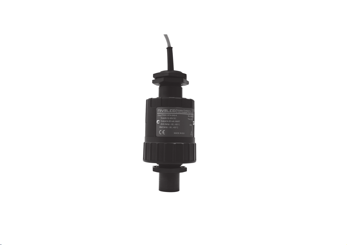
EasyTREK
SP-500
two-wire integrated ultrasonic level transmitter
Manufacturer
NIVELCO Process Control Co.
H-1043 Budapest, Dugonic s u. 11.
Tel.: (36-1) 889-0100 Fax: (36-1) 889-0200
sales
E-mail: @nivelco.com www.nivelco.com
:
spa5804a0600p_03 1 / 40
Page 2
)
m
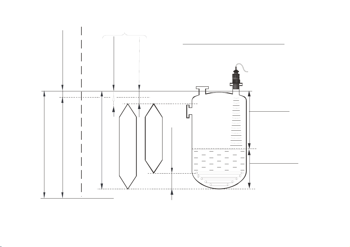
Min . me asu ring dist ance
m
m
BASIC CONCEPTS AND ELEMENTS
OF ULTRASONIC MEASUREMENT
)
M
Max (X. measuring dis tance o f th e de vic e
Device data Application data
2 / 40 spa5804a0600p_03
Min (X. measuring dist ance
Max. measurement range of the device
Aut omati c cl ose- end blo cking
Default : P 05 = X
Max. distance to be measured (H)
Manuakl close-end blocking
Programmed : P05 > X
DIST = Distance (measured)
Tran smitte d ra ng e
Far end blocking
Defaults: P0 6 = 0
Programmed measu reme nt range
LEV = Level
( : H-DIST )ca lcula ted
VOL = Vo lume
(calculated from LEV)
Measurement
Page 3

CONTENTS
INTRODUCTION ......................................................................................... 5
1.
2. TECHNICAL DATA ..................................................................................... 6
2.1. General data ...................................................................................... 6
2.2. Special data ....................................................................................... 7
2.3. Accessories ........................................................................................ 7
2.4. Order codes (Not all combinations are available) .............................. 7
2.5. Dimensions ........................................................................................ 8
3. INSTALLATION .......................................................................................... 9
3.1. Liquid Level Measurement ................................................................. 9
3.2. Open channel flow measurement .................................................... 11
4. WIRING ..................................................................................................... 11
5. PUTTING INTO OPERATION ................................................................... 12
5.1. Usage ............................................................................................... 12
5.2. Special conditions of safe use ......................................................... 12
5.3. Programming ................................................................................... 13
5.3.1. Measurement configuration ................................................. 13
5.3.2. Current Output .................................................................... 20
5.3.3. Relay Output ....................................................................... 22
5.3.4. Digital communication ......................................................... 23
5.3.5. Measurement optimisation .................................................. 23
5.3.6. Volume (content) measurement .......................................... 27
5.3.7. Open channel flow measurement ....................................... 28
5.3.8. Programming the VOLUME / MASS / FLOW TABLE) ........ 34
5.3.9. Informational parameters (read only parameters) ............... 35
5.3.10. Additional parameters of the flow metering ......................... 36
5.3.11. Other parameters ................................................................ 36
6. MAINTENANCE AND REPAIR ................................................................ 37
6.1. Firmware upgrade............................................................................ 37
7. ERROR CODES ........................................................................................ 37
8. PARAMETER TABLE ............................................................................... 38
9. SOUND VELOCITY VALUES IN DIFFERENT GASES ........................... 40
spa5804a0600p_03 3 / 40
Page 4
spa3804a0600p_02 4 / 40
Page 5
Thank you for choosing a NIVELCO instrument.
We are sure that you will be satisfied throughout its use.
1. INTRODUCTION
Application
The EasyTREK compact ultrasonic level transmitters from NIVELCO are
excellent tools for level measurement of liquids.
Level measurement technology based on the non-contacting ultrasonic
principle is especially suited for applications where, for any reason,
no physical contact can be established to the surface of the material to
be measured.
Principle of Operation
The ultrasonic level metering technology is based on the principle of
measuring the time required for the ultrasound pulses to make a round trip
from the sensor to the level to be measured and back. The sensor emits an
ultrasonic pulse train and receives the echoes reflected. The intelligent
electronic device processes the received signal by selecting the echo reflected
by the surface and calculates from the time of flight the distance between the
sensor and the surface which constitutes the basis of all output signals of the
EasyTREK.
Minimum measuring distance (Xm) is determined by the design of the unit within which the measurement is not possible (Dead Zone) its value is according with
P05 on page 18. Since measurement is impossible within this range material should not get into this zone.
Maximum measuring distance (X
) is the greatest distance (determined by the design of the unit) which can be measured by the unit under ideal conditions.
M
(See parameter P04 on page 17). Maximum measuring distance of the actual application (H) must not be greater than X
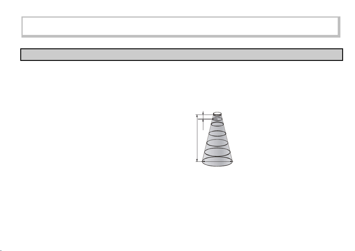
A Total beam angle of 5 – 7 at -3 dB as is featured by most of Nivelco’s
SenSonic transducers ensuring a reliable measurement in narrow silos with
uneven side walls as well as in process tanks with various protruding objects.
Furthermore, as a result of the narrow beam angle – the emitted ultrasonic signals
have an outstanding focusing – deep penetration through gases, vapour and foam
is ensured.
XD
1 m –
m
X
M
X
D
2 m –
5 m –
10 m –
15 m –
0.21 m
0.3 m
0.56 m
1 m
1.45 m
M
Diameters corresponding
to
5° beam angle.
.
spa5804a0600p_03 5 / 40
Page 6
2. TECHNICAL DATA
2.1. GENERAL DATA
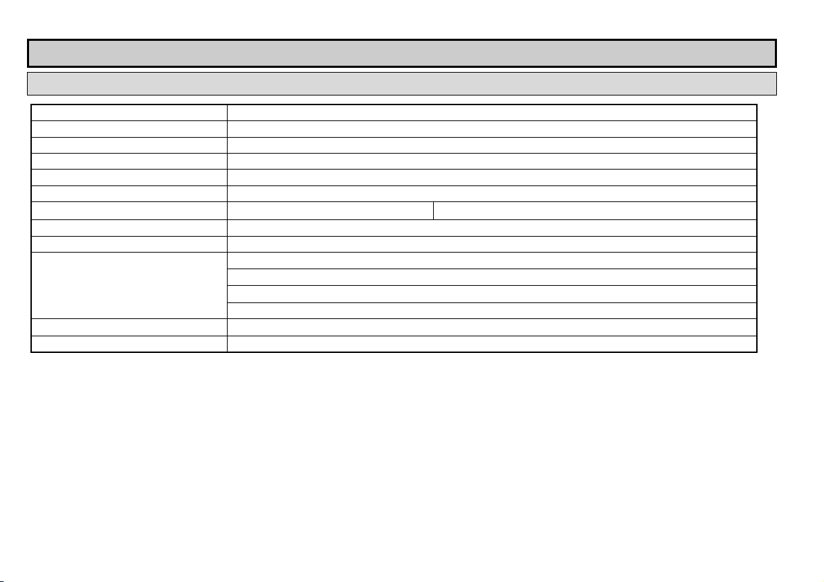
Transducer / enclosure materials Polypropylene (PP), PVDF, PTFE/PP
Process temperature PP, PVDF and PTFE transducers -30 °C … +90 °C
Ambient temperature -30 °C … +80 °C
(1)
Pressure
Seals PP transducer: EPDM; All other transducer versions: FPM
Ingress protection IP68
Power supply 10
Accuracy
Resolution Depending on the measured distance: <2 m: 1 mm, 2 – 5 m: 2 mm, 5 – 10 m: 5 mm, >10 m: 10 mm
Outputs
Electrical connection
Electrical protection Class III SELV
(1) For pressures below 1 bar consult with your representative at NIVELCO
(2) Under optimal circumstances of reflection and stabilised transducer temperature.
(3) Only partial operation is provided. Reliable operation without any restrictions is guaranteed at >11 V terminal voltage.
(Absolute) 0.05 – 0.3 MPa (0.5 – 3 bar)
(3)
– 36 V DC with HART communication 40 mW – 720 mW, Galvanic isolation; protection against surge transients
(2)
(0.1% measured + 0.025% max.) or (0.05% max.) whichever is greater
Analogue: 4 – 20 mA, (3.9 – 20.5 mA), R
SPDT relay, 30 V / 1 A DC; 48 V / 0.5 A AC
Serial communication: HART interface (terminal resistor ≥ 250 Ohm)
Programming / diagnostic interface: 3.3 V LVDS, 100 mA max., Galvanic isolated
2
6 x 0.5 mm
shielded cable 6 mm x 5 m (available max. length 30 m)
= (Ut – 10 V) / 0.02 A, Galvanic isolation; protection against surge transients
tmax
6 / 40 spa5804a0600p_03
Page 7
2.2. SPECIAL DATA
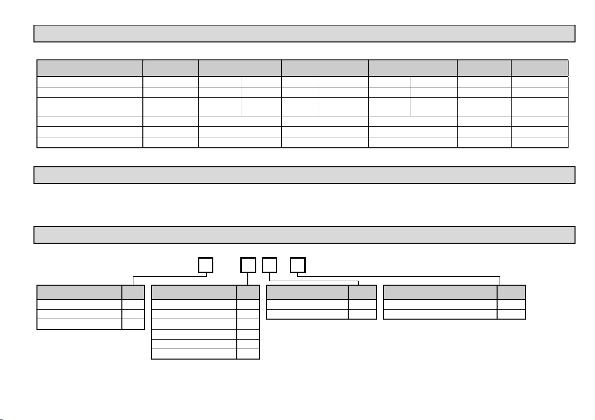
SPECIAL DATA FOR PP, PVDF AND PTFE TRANSDUCERS (ALSO APPLIES TO Ex MODELS)
Type
Transducer material PP or PVDF PP, PVDF PTFE PP, PVDF PTFE PP, PVDF PTFE PP or PVDF PP or PVDF
Max. measuring distance (XM) [m / ft] 3 / 10 5 / 16 4 / 13 8 / 26 6 / 20 10 / 33 7 / 23 12 / 39 18 / 59
Min. measuring distance *
(Dead band) (X
Total beam angle (-3dB) 5° 6° 5° 7° 5° 5°
Measuring frequency 120 kHz 80 kHz 80 kHz 50 kHz 60 kHz 40 kHz
Process connection 1" BSP / NPT 1" BSP and 1½" BSP / NPT 1" BSP and 2" BSP / NPT 1" BSP and 2" BSP / NPT 1" BSP 1" BSP
* (from the transducer face)
) [m / ft]
m
SP-5A- SP-59 - SP-58- SP-57- SP-56- SP-54-
0.15 / 0.49 0.18 / 0.59 0.25 / 0.82 0.2 / 0.65 0.25 / 0.82 0.25 / 0.82 0.35 / 1.2 0.25 / 0.82 0.35 / 1.2
2.3. ACCESSORIES
Warranty Card
Installation and Programming Manual
Declaration of Conformity
2.4. ORDER CODES (NOT ALL COMBINATIONS ARE AVAILABLE)
EasyTREK
HOUSING MATERIAL CODE RANGE M/FEET CODE PROCESS CONNECTION CODE OUTPUT / EX CODE
PP A 18/59 4 1"; 1½", 2" BSP thread 0 4 – 20 mA / HART 4
PVDF B 12/39 6 1"; 1½", 2" NPT thread N 4 – 20mA / Relay / HART
PTFE / PP T 7/23; 10/33 * 7
6/20; 8/26 * 8
4/13; 5/16 * 9
3/10 A
* Measuring range depends on the material of the transducer
S
P – 5 –
N
The order code of an Ex version should end in ‘Ex’
spa5804a0600p_03 7 / 40
Page 8
2.5. DIMENSIONS
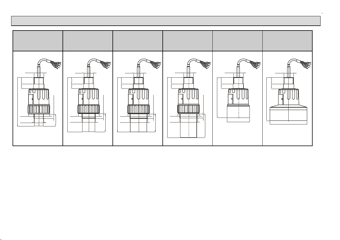
EasyTREK
SP-5A- /
PP, PVDF
EasyTREK
SP-59- /
PP, PVDF, PTFE
EasyTREK
SP-58- /
PP, PVDF, PTFE
EasyTREK
SP-57- /
PP, PVDF, PTFE
EasyTREK
SP-56- /
PP, PVDF
EasyTREK
SP-54- /
PP, PVDF
1" BSP
2216
~612
Ø47
1" BSP
1" NPT
BSP 15, NPT 22
40
8 / 40 spa5804a0600p_03
~202
2216
Ø47
2" BSP
2" NPT
1" BSP
BSP 15, NPT 22
80
~135
2216
1" BSP
Ø75
1" BSP
2216
~144
Ø124
1" BSP
2216
~182
Ø47
1" BSP
1" NPT½½
BSP 15, NPT 22
60
~182
2216
Ø47
2" BSP
2" NPT
1" BSP
BSP 15, NPT 22
60
Page 9
3. INSTALLATION
3.1. LIQUID LEVEL MEASUREMENT
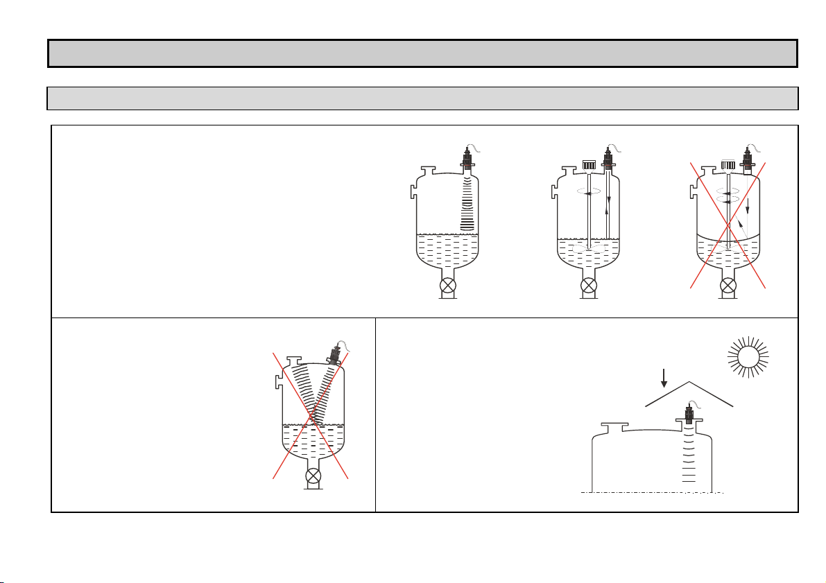
POSITION
The ideal position of the EasyTREK is on the radius
r = (0.3 – 0.5) R of the (cylindrical) tank / silo.
(Take also sonic cone on page 5 into consideration.)
SENSOR ALIGNMENT
The sensor face has to be parallel to the
surface of the liquid within 2 – 3.
TEMPERATURE
Make sure that the transmitter is
protected against overheating by
direct sunshine.
Sunshade
spa5804a0600p_03 9 / 40
Page 10
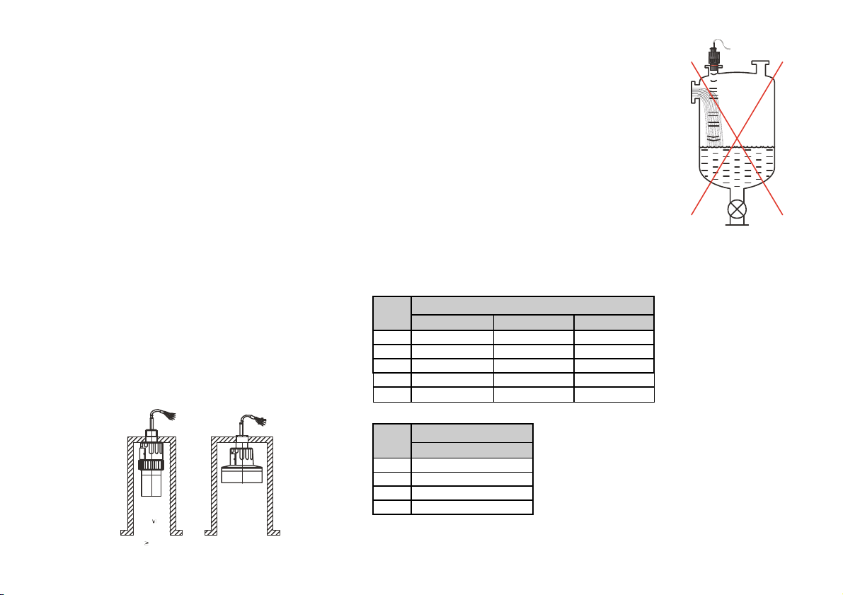
OBSTACLES
Make sure that no objects (cooling pipes, bracing members,
thermometers etc.) protrude into the sensing cone of the ultrasonic
beam.
Remark: EasyTREK programming allows one fixed object that would
otherwise disturb the measurement to be blocked out. (see P29 of
programming).
FOAM
Foaming of the liquid surface may render ultrasonic level metering
impossible. If possible, a location should be found, where foaming is
the least (device should be located as far as possible from liquid
inflow) or a stilling pipe or well should be used.
WIND
Intensive air (gas) movements in the vicinity of the ultrasonic cone
is to be avoided. A strong draft of wind may "blow away" the
ultrasound. Devices with lower measuring frequency (40, 20 kHz)
are recommended.
FUMES / VAPOURS
For closed tanks containing chemicals or other liquids, which
creates fume/gases above the liquid surface especially for outdoor
tanks exposed to the sun, a strong reduction of the nominal
measuring range of the ultrasonic device is to be considered during
device selection. Devices with lower measuring frequency
(40, 20 kHz) are recommended in these cases.
STAND-OFF
The structure of the stand off pipe should be rigid; the inner rim where the ultrasonic beam leaves the pipe should be rounded.
100ØD
10 / 40 spa5804a0600p_03
L
SP – 59 SP – 58 SP – 57
150 50 60 60
200 50 60 75
250 65 65 90
300 80 75 105
350 95 80 120
D
L
min
SP – 54
90 130
200 140
350 150
500 160
Dmin.
L
350
D
min
Page 11
3.2. OPEN CHANNEL FLOW MEASUREMENT
The unit is suitable for open channel flow measurement with the constructive works listed in 5.3.8.
For ultimate accuracy, install the sensor as close as possible above the expected maximum water level (see minimum measuring range).
Install the unit in a place defined by the characteristics of the metering channel along the longitudinal axis of the flume or weir. In case of Parshall flumes
supplied by NIVELCO the location of the sensor is marked.
In some cases foam may develop on the surface. Make sure that the surface, opposite to the sensor, remains free of foam for proper sound reflection.
The unit should be fixed so that it‘s position would not change.
From measurement accuracy point of view the length of the channel sections preceding and following the measuring flume and their method of joining to the
measuring channel section are of critical importance.
Despite of the most careful installation, the accuracy of flow metering will be lower than that of specified for the distance measurement. The features of the
flume or weir applied will determine it.
Devices should be protected against overheating due to direct sunshine by using sunshades.
4. WIRING
Make sure the terminals in the box are not under power (Use shielded cable 7 x 0.5 mm2 – with relay
output, 4 x 0.5 mm2 – without relay output suggested in the technical data or stronger).
After powering the necessary programming can be performed.
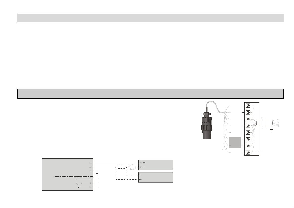
Wire colours:
Pink – relay C1 output White – I, one of the points of current loop, power supply and HART (polarity independent)
Grey – relay CC output Brown – I, other point of current loop, power supply and HART (polarity independent)
Blue – relay C2 output Black – GND, functional earthing and shielding point
Power supply
+HART
+Current output
C1 C2
TRANSMITTER
Relay
output
CC
I
white (brown)
brown (white)
black
pink
blue
grey
mA
R
Power supply
HART modem
White
Brown
Grey
Blue
Pink
Ye l l o w
Firmware updating
and diagnostic port
Extension of the integrated cable:
Should extension be needed the use of connection box is
suggested.
The shielding of the two cables should be connected and
grounded at the signal processing device.
Green
Blac k
Junction box
spa5804a0600p_03 11 / 40
Page 12
5. PUTTING INTO OPERATION
5.1. USAGE
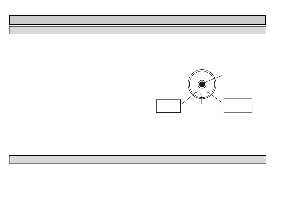
Subsequent to powering the correctly wired device would start to tick and after 10 – 20 s ECHO LED go on and 4 – 20 mA signal appears on the current output.
Measurement will be according to the factory setting. The factory setting is throughout apt to check proper working and to perform simple measurement tasks but
features residing in the unit can only be utilised by adjusting the EasyTREK to the application by programming. For sound knowledge of the operation features and
proper solving of difficult measurement applications the parts of the programming should carefully be studied.
indication:
LED
ECHO-LED
– On, if the unit detects proper echo
COM-LED
– Blinking on HART communication
– Is ON in the state of remote programming
RELAY-LED (optional)
– Lits, if CC-C2 is ON
– Does not lit, if CC-C1 is ON
Device can be reset to factory setting. Default of EasyTREK SP-300 is the following:
Measurement: level (LEV)
Zero level assigned to the maximum distance
Current output proportional to the level
4 mA and 0% assigned to zero level.
20 mA and 100% a assigned to the maximum level (minimum distance)
Error indication by the current output: holds last value.
Damping: 60 s.
5.2. SPECIAL CONDITIONS OF SAFE USE
The cable outside the unit should be fixed so that it should be free of loading.
The terminal box should be selected in accordance with the electrical class of the area.
View of the transmitter neck from above:
Red LED
„COM”
Red LED
„RELAY”
Cable
Red LED
„ECHO”
12 / 40 spa5804a0600p_03
Page 13
5.3. PROGRAMMING
The HART interface of the EasyTREK provides for access to the whole parameter set and possibility of their programming. Parameter set can be reached in two
different ways: by the use of the
– EView2 software run on the PC connected through HART modem to the loop or
– NIVELCO made MultiCONT multi-channel process control unit.
Since these access methods differ in their form and handling present manual does not review them. The information is contained in the relevant descriptions and
user’s manuals.
5.3.1. MEASUREMENT CONFIGURATION
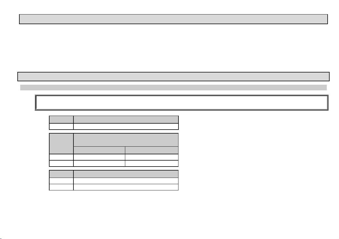
P00: - c b a Engineering Units FACTORY DEFAULT: 000
Programming of this parameter will result in loading the factory default with the corresponding engineering units.
Therefore all parameters should be set again!
a Operation
0 Liquid level measurement
Engineering units
b
(according to “c”)
Metric US
0 m ft
1 cm inch
c Calculation system
0 metric
1 US
spa5804a0600p_03 13 / 40
Page 14
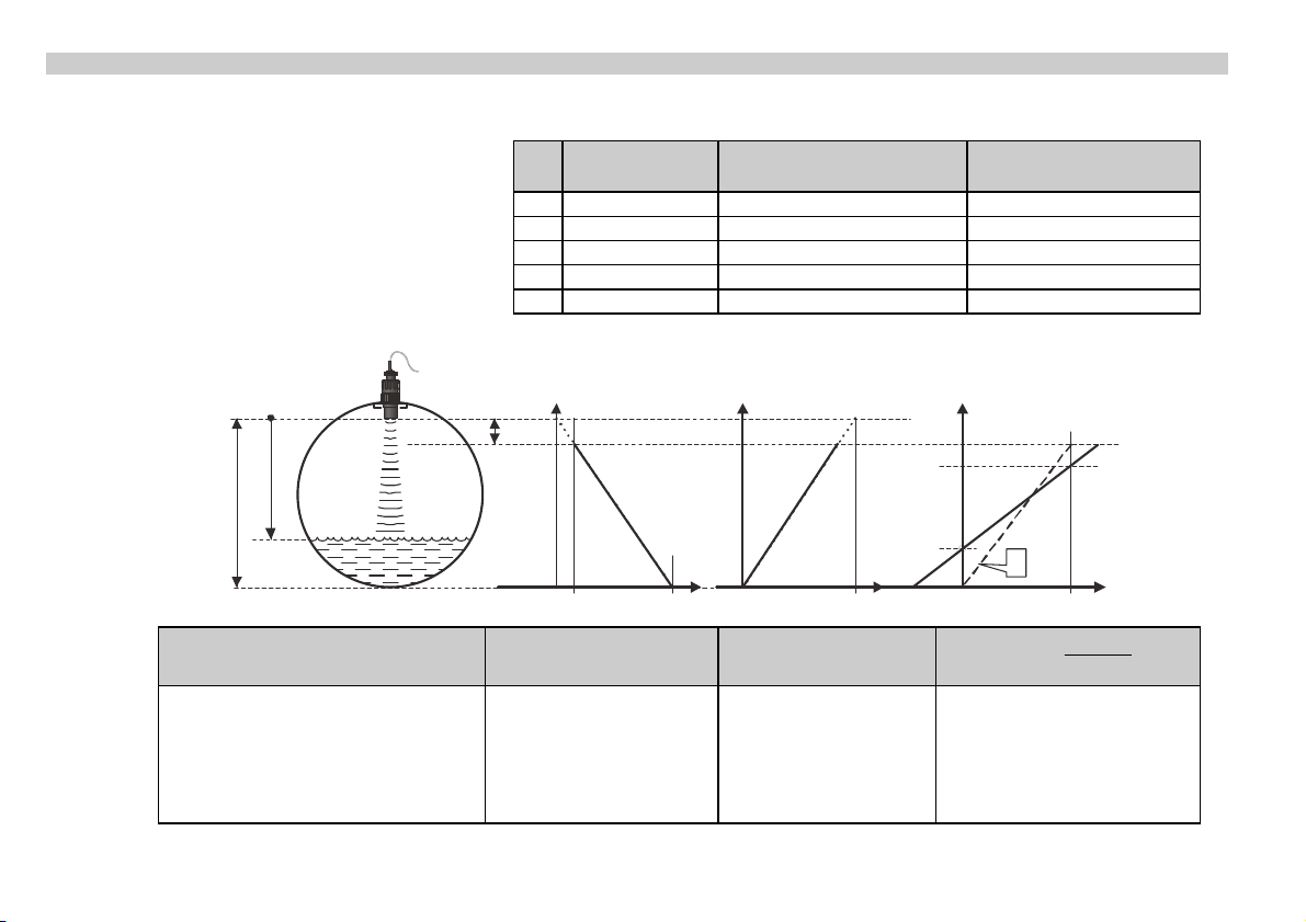
P01: - - 1 a Measurement Mode FACTORY DEFAULT: 11
Parameter value “a” will determine the basic measurement value that will be transmitted. Subsequently values for the relays are also relating to
these quantities.
a
Measurement
mode
Transmitted value Display symbol
0 Distance Distance DIST
1 Level Level LEV
2 Volume Volume VOL
3* Mass Mass MASS
4 Flow Flow FLOW
DIST
H
A
* See: P32
0
X
m
DIST
H
0
Transmitted value DIST LEV=H-DIST
Parameters to set P00
P01(a) = 0
P05 ≥ X
m
P00
P01(a) = 1
P04 = H
P05 ≥ X
P11
P10
LEV
H
D
0
LEV%= P10
100
*LEV
P00
P01(a) = 2
P04 = H
m
P05 ≥ X
P10 = X
P11 = X
LEV %
[%]
P10P11
XH
m
m
0%
100%
14 / 40 spa5804a0600p_03
Page 15
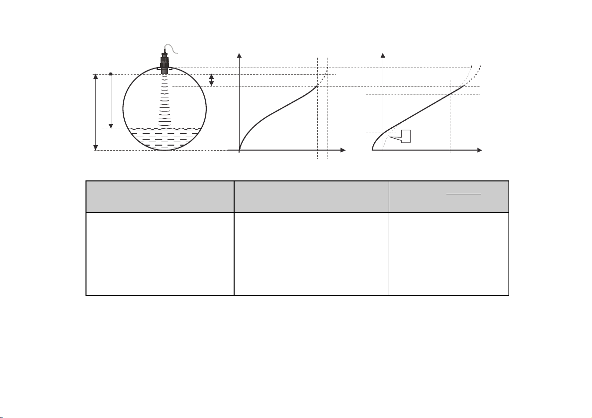
A
DIST
H
0
CB
VOL
P11
P10
D
0100
VOL %
[%]
P10P11
Transmitted value
Parameters to set P00
P01(a) = 3
P02(b)
P04 = H
P05 ≥ X
P40 … P45
f
P40…P45
VOL
(H-DIST)
m
VOL%= P10
P00
P01(a) = 4
P02(b)
P04 = H
P05 ≥ X
P10 = X
P11 = X
*VOL
XH
m
m
0%
100%
P40 … P45
A: Shortest measurable distance
B: Volume (content) pertaining to the greatest measurable level
C: Whole value of the vessel
D: diagram valid for the default value of P10 P11
spa5804a0600p_03 15 / 40
Page 16
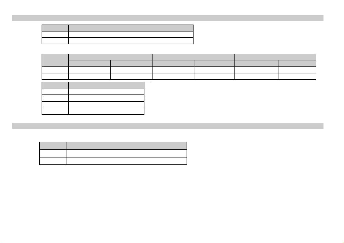
P02: - c b a Calculation units FACTORY DEFAULT: 000
a Temperature
0 °C
1 °F
This table is interpreted according to P00(c), P01(a) and P02(c) and is irrelevant in case of percentage measurement [ P01(a)= 2 or 4 )]
b
Metric US Metric US Metric US
Volume Weight (set also P32) Volume flow
0 m3 ft3 – lb (pound) m3/time ft3/time
1 litre gallon tons tonnes litre/time gallon/time
c Time
0 s
1 min
2 hour
3 day
Attention!
EasyTREK is a level transmitter. Although it can be used for
measuring weight, due to factors involved in doing so, accuracy
may essentially be influenced.
P03: - - - a Temperature compensation mode FACTORY DEFAULT: 0
Temperature compensation mode
a Temperature compensation mode
0 Automatic
1 Manual
Automatic: The compensation is done with using the value measured by the temperature sensor.
Manual: The compensation is done with a fixed setpoint temperature value independently of the measured value (P07).
16 / 40 spa5804a0600p_03
Page 17
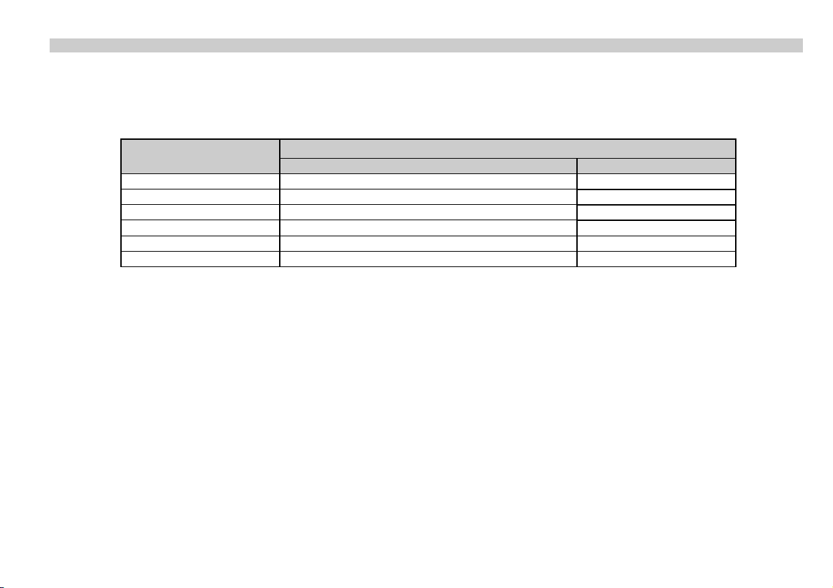
P04 - - - - Maximum Distance to be Measured (H) FACTORY DEFAULT: XM as per chart
This is the only parameter that has to be programmed for each application other than distance (however to avoid disturbing effect of
possible multiple echoes it is suggested to do this in distance measurement applications too).
The maximum distance to be measured is the greatest distance between the surface of the transducer and the farthest level to be measured.
The factory programmed, greatest distances (DEFAULT values) which can be measured by the units are listed in the table below. For the actual
application the maximum distance to be measured i.e. the distance between the sensor and the bottom of the tank should be entered in P04.
EasyTREK
Level transmitter for liquids
Transducer material PP / PVDF Transducer material PTFE
Maximum measuring distance XMm/feet
SP_-5A 3 / 10 SP_-59 5 / 16 4 / 13
SP_-58 8 / 26 6 / 20
SP_-57 10 / 33 7 / 23
SP_-56 12 / 39 SP_-54 18 / 59 -
Since the level is determined by calculating the difference between the value set in P04 and distance (DIST) is measured by the unit, it is
essential that the correct value of (H) is set in P04. To obtain the best accuracy it is suggested that this distance is measured in the empty tank.
spa5804a0600p_03 17 / 40
Page 18
P05: - - - - Minimum measuring distance (Dead zone – Close-end blocking) FACTORY DEFAULT: Xm as per chart
The range, beginning with the sensor’s surface, within which (due to the physical restraint of the ultrasound measurement system) measurement can
not be made, is called the dead zone. The EasyTREK will not accept any echo within the
blocking distance set here.
Close-end blocking may be represented as the extension of the dead zone within which a possible echo will not be taken into consideration making
possible to exclude disturbing objects near to the sensor.
Automatic Close-end blocking =Dead Band control (P05 = X
)
m
Device with factory default will automatically set the smallest possible dead band depending on the conditions of the operation. This will be under
optimal conditions a bit smaller in unfavourable circumstances greater than value given in the chart.
Manual Close-end-blocking with limitation ≥ dead zone (P05>X
)
m
By entering a value, higher than the factory default the close-end blocking will be either the value programmed in P05 or the actual dead zone
distance (influenced by the actual conditions of the application) whichever is greater.
EasyTREK
for liquids
Sensor material PP / PVDF
Minimum measuring distance Xm m/feet
Sensor material PTFE
SP_-5A 0.15 / 0.49 SP_-59 0.18 / 0.59 0.25 / 0.82
SP_-58 0.2 / 0.65 0.25 / 0.82
SP_-57 0.25 / 0.82 0.35 / 1.2
SP_-56 0.25 / 0.82 SP_-54 - -
18 / 40 spa5804a0600p_03
Page 19
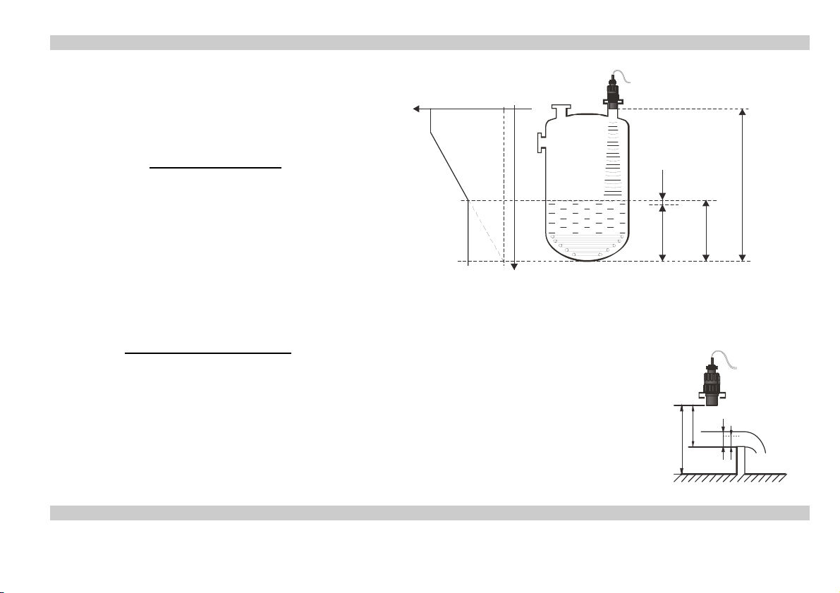
P06: - - - - Far-end blocking FACTORY DEFAULT: 0
Far-end blocking is the range below the level set
in parameter P06. The far-end blocking can be
used to avoid disturbing effect of stirrer or heaters
at the bottom of the tanks. Detecting echoes in
20 mA
4 mA
this range the unit provides special signals.
A.) Measuring level or content
Level sinking below
X/8
the value of P06 current output is according to
the value of the far-end blocking and further
below SUB 0 (7/8 of P06) the ERROR CODE
10 will be transmitted via HART
SUB 0
P06=X
Level rising over value of far-end blocking:
The calculation of level and volume will be based on the programmed tank dimensions, therefore the measured or calculated process values will
not be influenced in any way, by the far end blocking value.
B.) Open channel flow metering
Far-end blocking will be used for those small levels below which the accurate volume flow calculation is no longer
possible.
Level in the flume/weir sinking below the blocked out range:
- Output current value will be according to the value of Q = 0
- 0 value transmitted via HART for display of „No Flow” or 0
P04
P46
h
Level in the flume/weir rising over the blocked out range:
The calculation of volume flow will be based on the programmed flume/weir data; therefore the measurement
values will not be influenced in any way, by the far end blocking value.
P07: - - - - Temperature compensation with fixed value FACTORY DEFAULT: 20 ºC
Manual temperature compensation value
H
P06
spa5804a0600p_03 19 / 40
Page 20
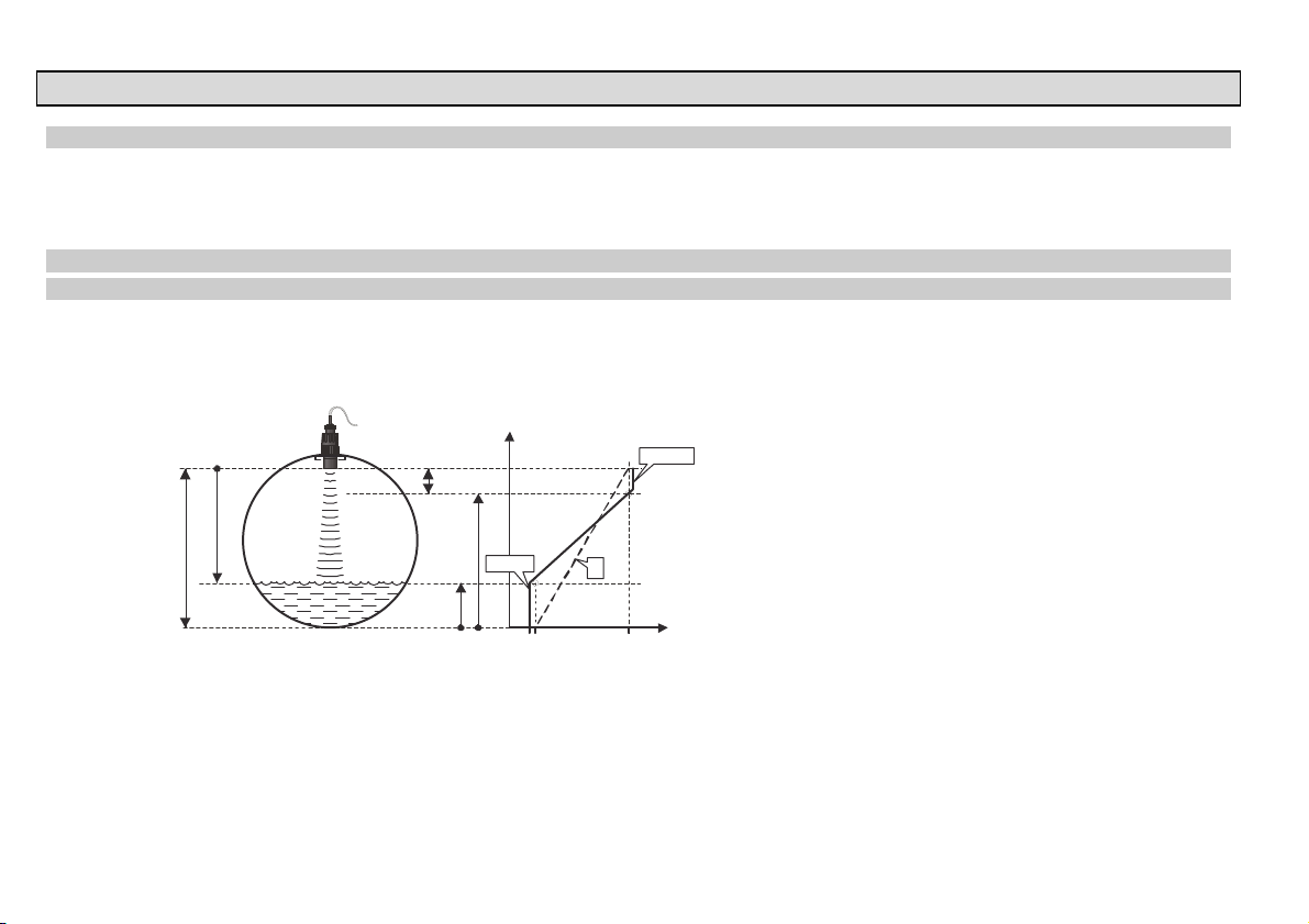
5.3.2. CURRENT OUTPUT
P08: - - - - Fixed current output FACTORY DEFAULT: 0
Fixed current output setting parameter
With this parameter the output current can be set to a fixed value between 3.8 mA and 20.5 mA.
This automatically overwrites the 4 mA value set by the HART multidrop mode and the transmitted analogue output current is deactivated.
P10: - - - - Value (of distance, level, volume or flow) assigned to 4 mA current output FACTORY DEFAULT: 0
P11: - - - - Value (of distance, level, volume or flow) assigned to 20 mA current output FACTORY DEFAULT: XM – X
Values are interpreted according to P01(a). Assignment can be made so that the proportion between the change of the (measured or calculated)
process value and the change of the current output be either direct or inverse. E.g. level 1 m assigned to 4 mA and level 10 m assigned to 20 mA
represents direct proportion and level 1 m assigned to 20 mA and level 10 m assigned to 4 mA represents the inverse proportion.
Transmitting level
m
DIST
H
20 / 40 spa5804a0600p_03
LEV
A
P11
3.8 mA
P10
04 20
20.5 mA
D
I
out
[mA]
A: Smallest measurable dist.
D: diagram valid for default
values of P10 and P11
Page 21
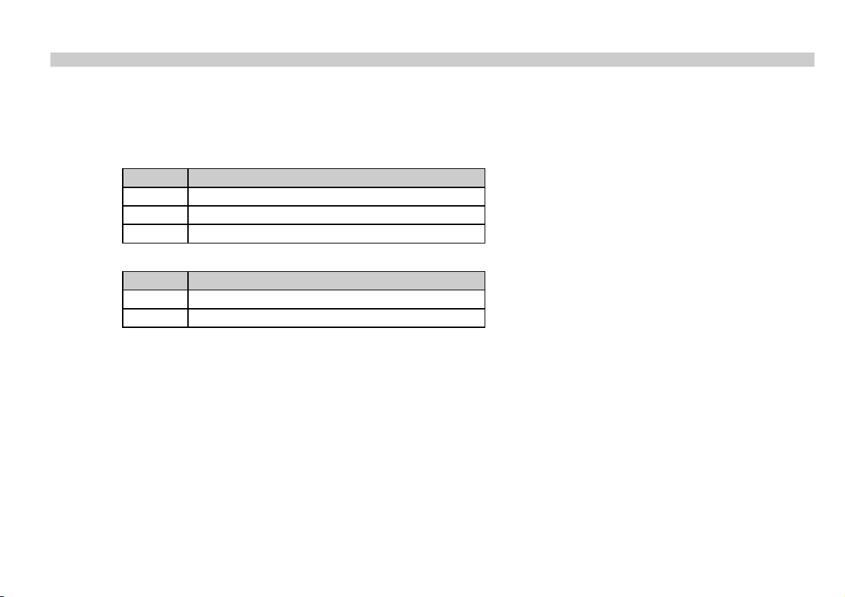
P12: - - b a Current output mode FACTORY DEFAULT: 0
Error indication by output current:
Error will be indicated by the EasyTREK transmitter on the current output according to the set value as long as error is present.
(Error codes are given in Chapter 7).
a Error indication by output current
0 HOLD (hold last value)
1 3.8 mA
2 22 mA
Current output mode:
b Current output mode
0 Automatic
1 Manual
Automatic: The current output value is calculated from the measured value, the transmitter output is active.
Manual: The current output value is not calculated from the measured value, but a fixed (according to P08) current output value is transmitted.
In this mode, the current output error setting is irrelevant.
This parameter overwrites the HART multidrop communication mode 4 mA value!
spa5804a0600p_03 21 / 40
Page 22
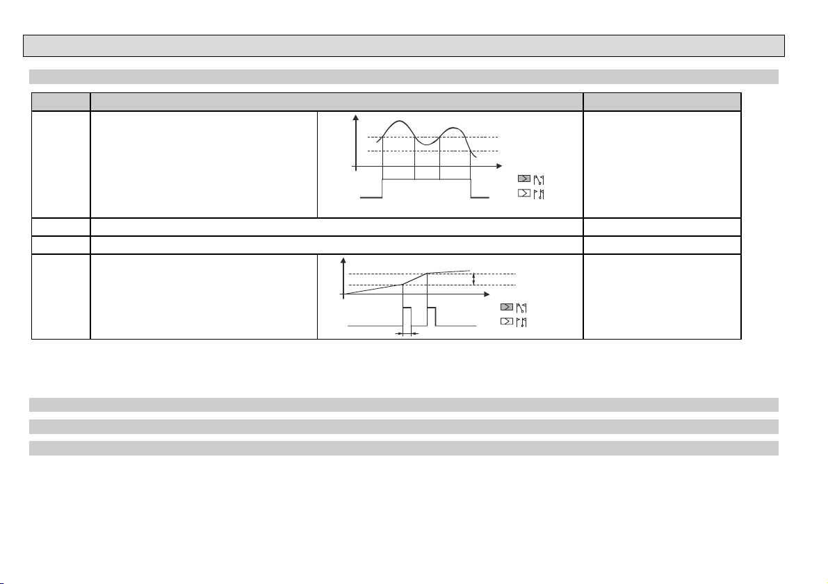
c
5.3.3. RELAY OUTPUT
P13: - - - a Relay function
a Relay function Also set:
0 DIFFERENTIAL LEVEL CONTROL
(Hysteresis control)
Relay is energised if the measured or
calculated value exceeds the value set in
P14 Relay is de-energised if the measured
or calculated value descends under the value
set in P15
Level
Relay
P14
P15
Time
Energis ed:
De-energi sed:
C2 C1
P14, P15
There is a need to set (in level
min 20mm) hysteresis between
P14 and P15
P14 > P15 – normal operation
P14 < P15 – inverted operation
1 Relay is energised in case of Echo Loss -
2 Relay is de-energised in case of Echo Loss -
3 COUNTER
Used for open channel flow metering.
A 140 msec pulse is generated every 1, 10,
100, 1.000 or 10.000 m3 according to P17.
20 m
10 m
TOT
3
3
Relay
200 mse
1 (P1)0 m 7
Energis ed:
De-energised:
3
Time
C2 C1
P17 = 0: 1 m
P17 = 1: 10 m
P17 = 2: 100 m
P17 = 3: 1.000 m
P17 = 4: 10.000 m3
3
3
3
3
In de-energised state of the device the „C1” circuit is closed.
FACTORY DEFAULT: 2
P14: … Relay parameter – Operating value FACTORY DEFAULT: 0
P15: … Relay parameter – Releasing value FACTORY DEFAULT: 0
P17: … Relay parameter – Pulse rate FACTORY DEFAULT: 0
FACTORY DEFAULTS: P14=0, P15=0, P17=0
22 / 40 spa5804a0600p_03
Page 23
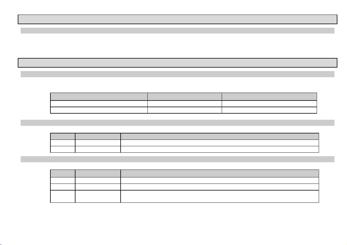
5.3.4. DIGITAL COMMUNICATION
P19: - - - a Short (HART) address of the unit FACTORY DEFAULT: 2
These addresses with 0 – 15 are, in accordance with the HART standard, for distinguishing units in the same loop.
Address: 0 current output of 4 – 20 mA operational
Address: 1 – 15 current output is fixed to 4 mA.
5.3.5. MEASUREMENT OPTIMISATION
P20: - - - Damping FACTORY DEFAULT: 60 SEC
Damping time is used to damp the unwanted fluctuations of the output and display. If the measured value changes rapidly the new value will settle
with 1% accuracy after this set time. (damping according to an exponential function).
For testing only Applicable
No or moderate fume / waves 0 sec 0 sec
P22: - - - a Dome top tank compensation FACTORY DEFAULT: 0
P24: - - - a Target tracking speed FACTORY DEFAULT: 0
Heavy or dense fume or turbulent waves >6 sec >10 sec
This parameter can be used to reduce disturbing effect of possible multiple echoes
a Compensation Remark
0 OFF In case the EasyTREK is not mounted in the centre of the top and the top is flat.
1 ON In case the EasyTREK is mounted in the centre of a tank with dome-shaped top
In this parameter evaluation can be speed up at the expense of the accuracy.
a Tracking speed Remark
0 Standard For most applications
1 Fast For fast changing level
2 Special
Only for special applications (measuring range is reduced to 50% of the nominal value)
The measuring window is inactive and the EasyTREK will respond practically instantly to any target.
spa5804a0600p_03 23 / 40
Page 24
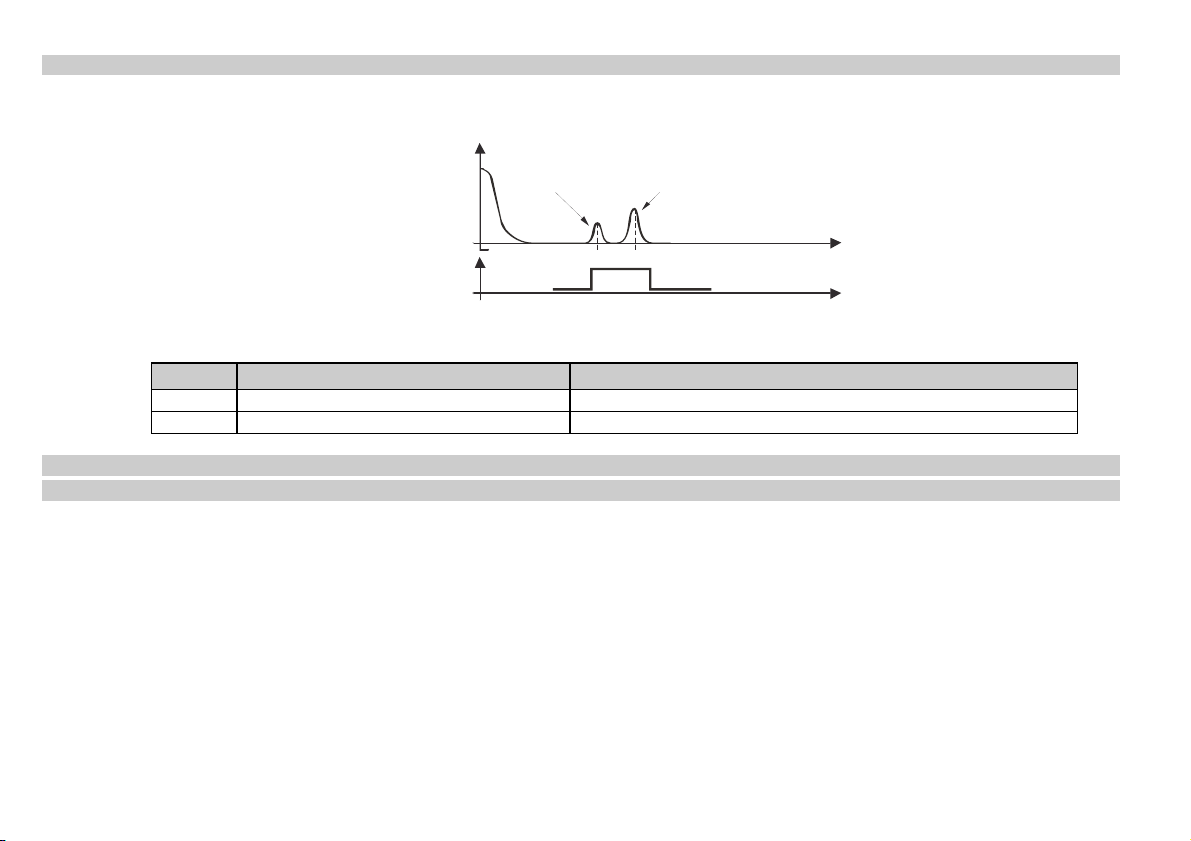
P25: - - - a Selection of Echo within the measuring window FACTORY DEFAULT: 0
A so-called measuring window is formed around the echo signal. The position of this measuring window determines the flight time for calculation of
the distance to the target. (the picture below can be seen on the test oscilloscope)
Received
Echo 1.
Echo 2.
signal
amplitude
t
t
Some applications involve multiple (target + disturbing) echoes even within the measuring window. Basic echo selection will be done by the QUEST+
software automatically. This parameter influences the echo selection only within the measuring window.
a Echo in the window to be selected Remark
0 With the highest amplitude Most frequently used
1 First one For liquids applications with multiple echoes within the Measuring Window
P26: - - - - Level elevation rate (filling speed) (m/h or ft/h) FACTORY DEFAULT: 2000 m/h
P27: - - - - Level descent rate (emptying speed) (m/h or ft/h) FACTORY DEFAULT: 2000 m/h
These parameters provide additional protection against echo loss in applications involving very heavy fuming. Correct setting increases reliability of
the measurement during filling and emptying. The parameters must not be smaller than the fastest possible filling/emptying rate of the actual
technology.
Attention! Level changing rate is rather different near to the conical or spherical bottom of such a vessel.
24 / 40 spa5804a0600p_03
Page 25
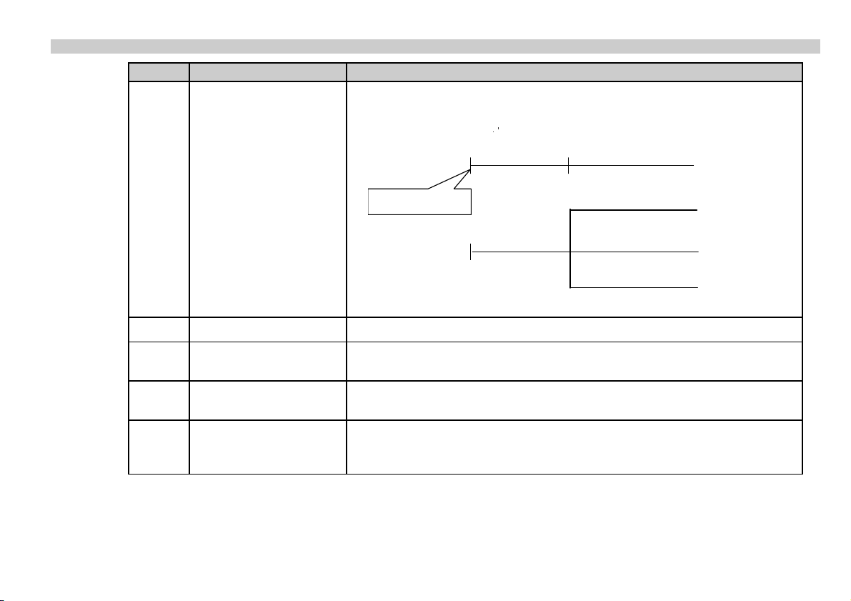
P28 - - - a Echo loss indication FACTORY DEFAULT: 0
a Echo loss indication Remark
During short echo-loss (for the period of 2(b+1)*P20) analogue output will hold last value. After
this period the current value according to the setting in P12 and via HART ERROR CODE 2 will
be transmitted.
HART
Holding value
Error Code 2
0 Delayed indication
Echo loss
Echo LED goes out
”2(b+1)*P20” time
Current 22mA P12=2
Current output
Holding value
Holding last value P12=0
Current 3,8mA P12=1
1 No indication For the time of echo-loss, analogue output will hold last value.
2 Filling simulation
3
Immediate indication
4 Empty tank indication
Losing echo during the filling process, transmitted value will increase according to the filling
speed set in P26
Losing echo, the current value (according to the setting in P12) and the ERROR CODE 2
(via HART) will immediately be transmitted.
Echo-loss may occur in completely empty tanks with a spherical bottom due to deflection of the
ultrasonic beam, or in case of silos with an open outlet. In such cases it may be useful to
indicate empty tank instead of echo loss.
spa5804a0600p_03 25 / 40
Page 26

P29 - - - - Blocking out of disturbing object FACTORY DEFAULT: 0
One fixed object in the tank, disturbing the measurement, can be blocked out. By the use of the Echo Map (P70) the precise distance of disturbing
object can be read out. This value should be entered in this parameter.
P31: - - - - Sound velocity at 20 C (m/s or ft/s depending on P00(c) FACTORY DEFAULT :: 343.8 (m/s), 1128 (ft/s)
This parameter should be used if the sound velocity in the gases above the measured surface differs largely from that of in the air. This is
recommended for applications where the gas is more or less homogeneous. If it is not, the accuracy of the measurement can be improved using
32-point linearisation (P48, P49).
For sound velocities in various gases see section “Sound Velocities”.
P32: - - - - Specific gravity FACTORY DEFAULT: 0
Entering a value (other than “0”) of specific gravity in this parameter, the weight will be displayed instead of VOL.
Engineering unit should be [kg/dm
3
] or [lb/ft3] depending on P00 (c)
26 / 40 spa5804a0600p_03
Page 27
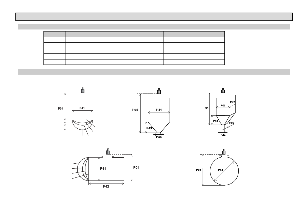
5.3.6. VOLUME (CONTENT) MEASUREMENT
P40: - - ba Tank shape FACTORY DEFAULT: 00
ba Tank shape Also to be set
b0 Standing cylindrical tank shape (value of “b” as below) P40 (b), P41
01 Standing cylindrical tank with conical bottom P41, P43, P44
02 Standing rectangular tank (with chute) P41, P42, P43, P44, P45
The value “a” determining the
shape of the tank should be
b3 Lying cylindrical tank shape (value of “b” as bellow) P40 (b), P41, P42
04 Spherical tank P41
P41-45: - - - - Tank dimensions FACTORY DEFAULT: 0
Standing cylindrical tank
with hemispherical bottom a = 0
b=0
b=1
b=2
P40
b=3
Standing cylindrical tank
with conical bottom a = 1, b = 0
Standing rectangular tank
with or without chute a = 2, b = 1
Lying cylindrical tank a = 3 Spherical tank a = 4, b = 0
Attention!
set first.
Plain bottom
P43, P44 and
P45 = 0
P40
b=3
b=2
b=1
b=0
spa5804a0600p_03 27 / 40
Page 28
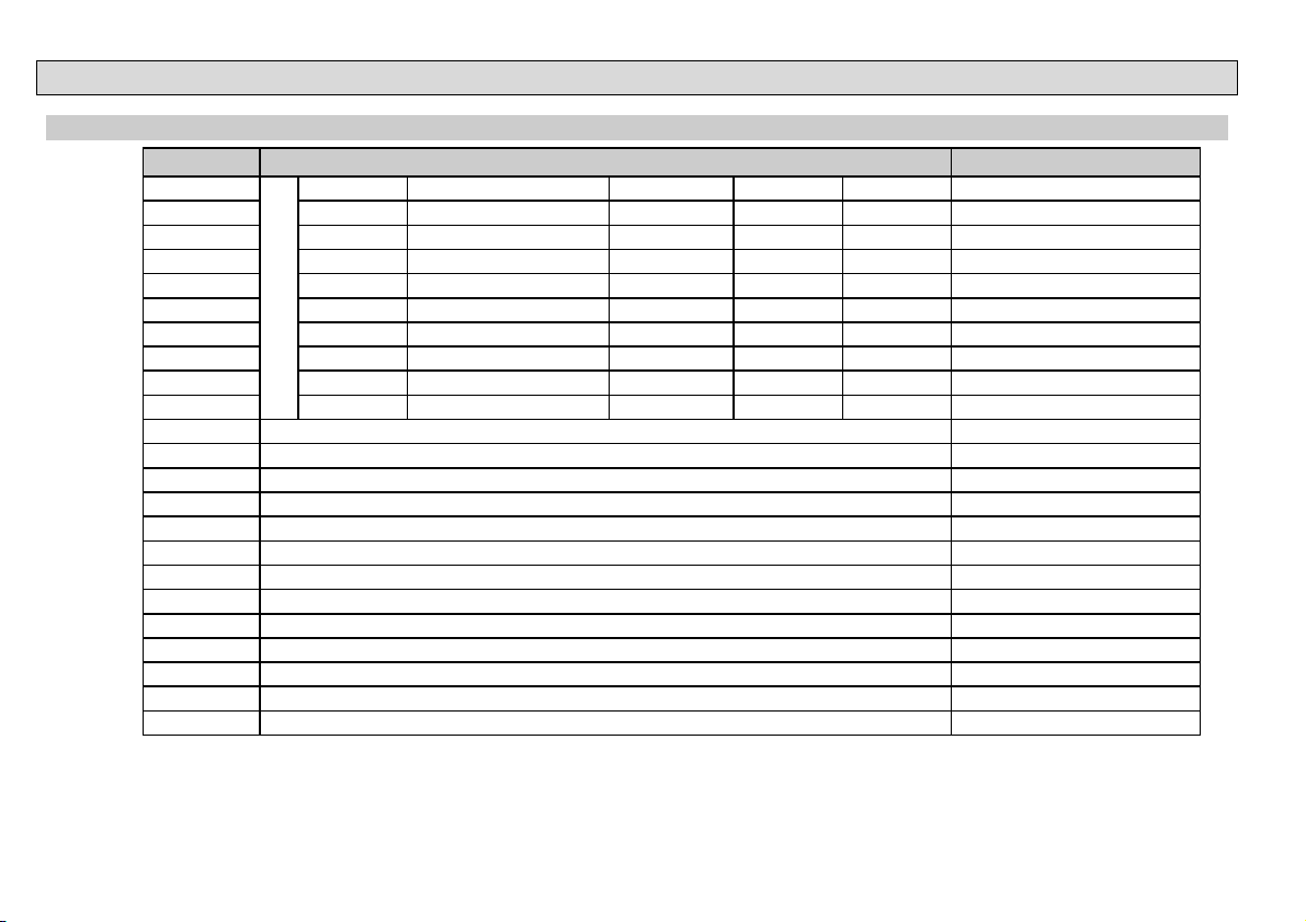
5.3.7. OPEN CHANNEL FLOW MEASUREMENT
P40: - - b a Devices, formula, data FACTORY DEFAULT: 00
ba
Type Formula Qmin [l/s] Qmax [l/s] “P” [cm]
00 GPA-1P1 Q [l/s]= 60.87*h
01 GPA-1P2 Q [l/s]= 119.7*h
02 GPA-1P3 Q [l/s]= 178.4*h
03 GPA-1P4 Q [l/s]= 353.9*h
04 GPA-1P5 Q [l/s]= 521.4*h
05 GPA-1P6 Q [l/s]= 674.6*h
06 GPA-1P7 Q [l/s]= 1014.9*h
07 GPA-1P8 Q [l/s]= 1368*h
08 GPA-1P9 Q [l/s]= 2080.5*h
NIVELCO Parshall channels
09 General PARSHALL flume P46, P42
10 PALMER-BOWLUS (D/2) P46, P41
11 PALMER-BOWLUS (D/3) P46, P41
12 PALMER-BOWLUS (Rectangular) P46, P41, P42
13 Khafagi Venturi P46, P42
14 Bottom-step weir P46, P42
15 Suppressed rectangular or BAZIN weir P46, P41, P42
16 Trapezoidal weir P46, P41, P42
17 Special trapezoidal (4:1) weir P46, P42
18 V-notch weir P46, P42
19 THOMSON (90°-notch) weir P46
20 Circular weir P46, P41
21 General flow formula: Q[l/s]= 1000*P41*h
Devices, formula, data Also to be set
1.552
0.26 5.38 30 P46
1.553
0.52 13.3 34 P46
1.555
0.78 49 39 P46
1.558
1.52 164 53 P46
1.558
2.25 360 75 P46
1.556
2.91 570 120 P46
1.56
4.4 890 130 P46
1.5638
5.8 1208 135 P46
1.5689
8.7 1850 150 P46
P42
, h [m] P46, P41, P42
28 / 40 spa5804a0600p_03
Page 29
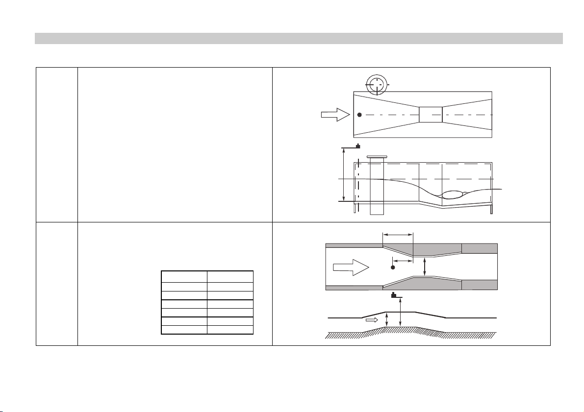
P41-45: Flume/weir dimensions FACTORY DEFAULT: 0
P40=00
.
.
.
.
P40=09
NIVELCO Parshall flumes (GPA1P1 – GPA-1P9)
For further details see the Manual of the Parshall flume
General Parshall flume
0.305 < P42(width) <2.44
026,0
569,1
P42
2.5 < P42
Q[l/s]= K*P42*h
P= 2/3*A
1.6
P42
305,0/h372s/lQ
P42 [m] K
3.05 2.450
4.57 2.400
6.10 2.370
7.62 2.350
9.14 2.340
15.24 2.320
EasyTREK
6
4
P
EasyTREK
EasyTREK
A
EasyTREK
h
P
P42
P46
spa5804a0600p_03 29 / 40
Page 30
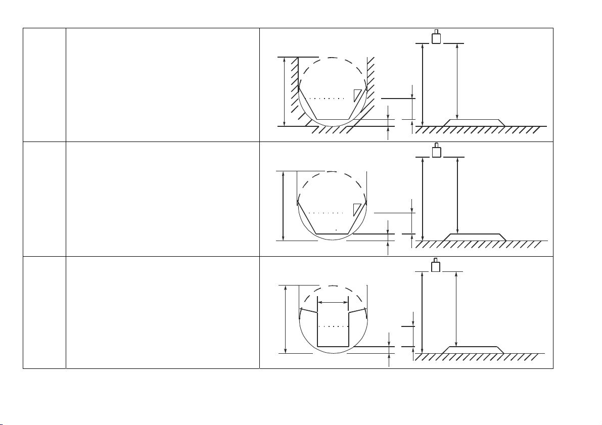
P40=10
Palmer-Bowlus (D/2) flume
3
/s]= f(h1/P41)*P41
Q[m
2.5
, where h1[m]= h+(P41/10)
P41 m
P41
P04
D
D/2
1
2
h
P46
P40=11
Palmer-Bowlus (D/3) flume
3
Q[m
/s]= f(h1/P41)*P41
P41 m
P40=12
Palmer-Bowlus (rectangular) flume
3
/s]= C*P42*h
Q[m
P41 m, P42 m
30 / 40 spa5804a0600p_03
2.5
, where h1[m]= h+(P41/10)
1.5
, where C= f(P41/P42)
P41
D
P41
D/10
P04
1
2
D/3
D/10
P42
D
D/10
h
P04
h
P46
P46
Page 31
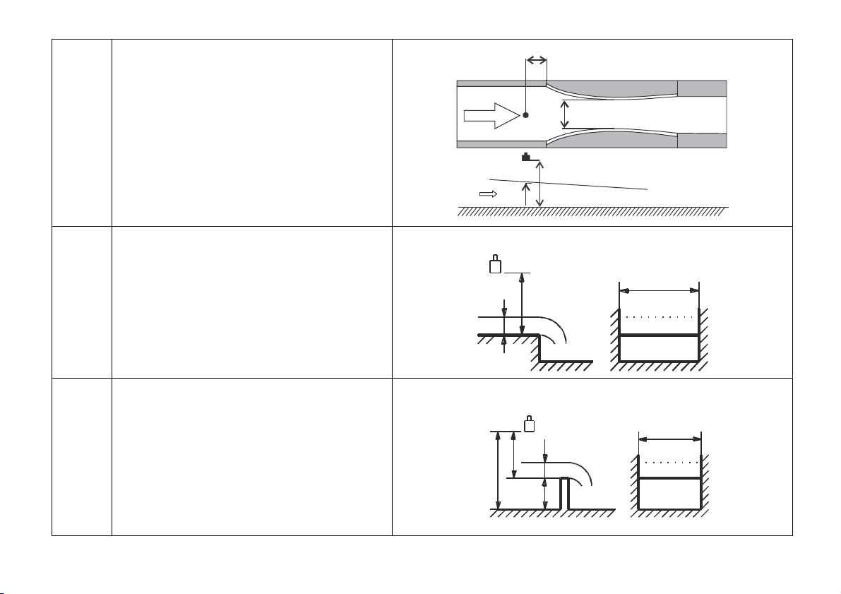
P40=13
Khafagi Venturi flume
3
/s] = 1.744 P42 h
Q [m
P42 m
h [m]
1.5
+ 0.091 h
15cm
2.5
EasyTREK
P42
P40=14
P40=15
Bottom step weir
0.0005 < Q [m
3
/s] < 1
0.3 < P42 [m] < 15
0.1 < h [m] < 10
3
Q [m
/s]= 5.073 P42 h
Accuracy:
10%
1.5
Suppressed rectangular or BAZIN weir
0.001 < Q [m3/s] < 5
0.15 < P41 [m] < 0.8
0.15 < P42 [m] < 3
0.015 < h [m] < 0.8
3
Q [m
/s] =1.77738(1+0.1378h/P41) P42 (h+0.0012)
Accuracy: 1%
1.5
EasyTREK
h
P04
P46
h
P40=14
P42
P46
P40=15
P42
P46
h
P41
spa5804a0600p_03 31 / 40
Page 32
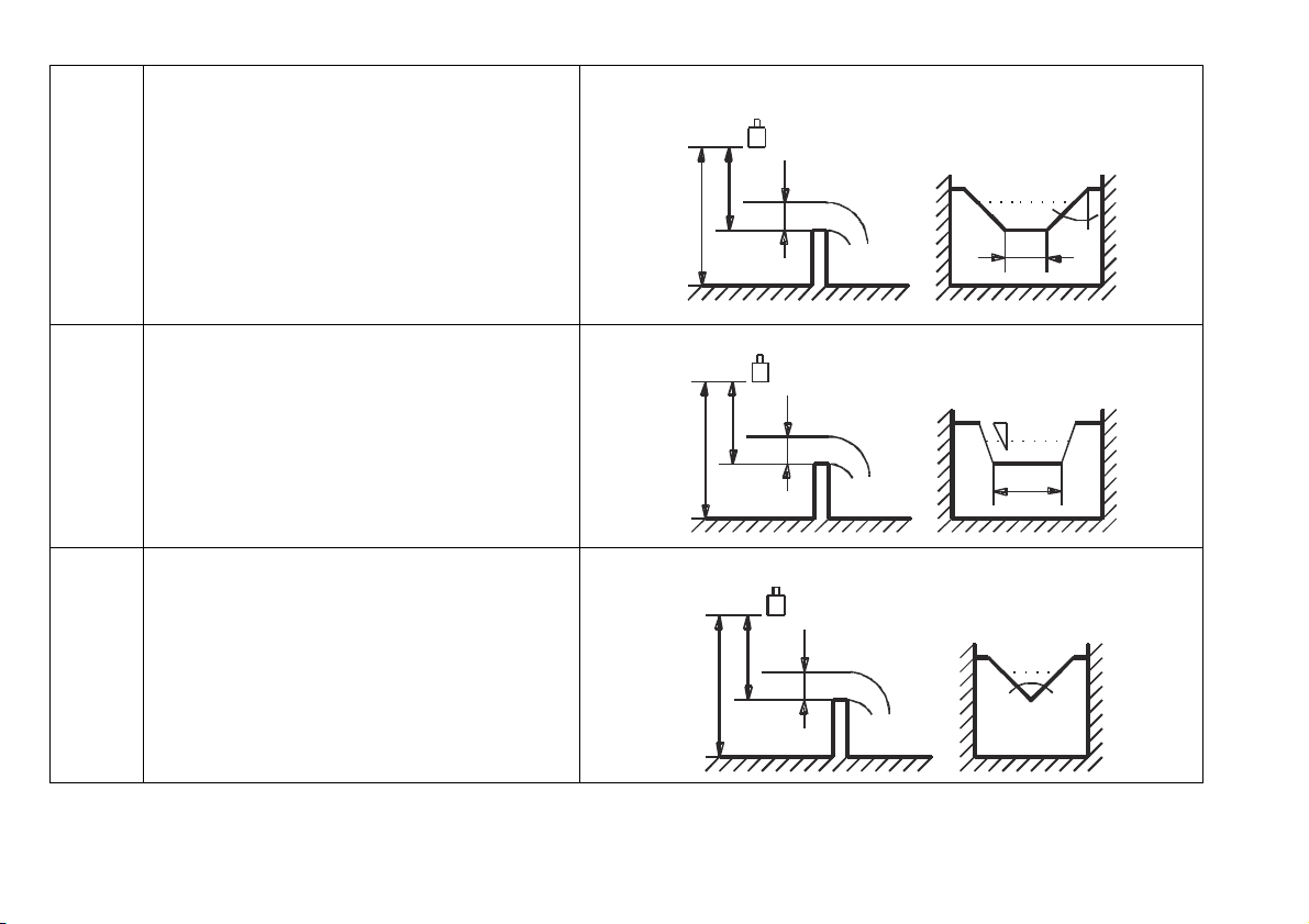
P40=16
P40=17
P40=18
Trapezoidal weir
0.0032 < Q [m
3
/s] < 82
20 < P41[°] < 100
0.5 < P42 [m] < 15
0.1 < h [m] < 2
3
Q [m
/s] = 1.772 P42 h
Accuracy:
5%
1.5
+ 1.320 tg(P41/2) h
Special trapezoidal (4:1) weir
0.0018 < Q [m3/s] < 50
0.3 < P42 [m] < 10
0.1 < h [m] < 2
3
Q [m
/s] = 1.866 P42 h
Accuracy:
3%
1.5
V-notch weir
0.0002 < Q [m
3
/s] < 1
20 < P42[°] < 100
0.05 < h [m] < 1
3
Q[m
/s] = 1.320 tg(P42/2) h
Accuracy:
3%
2.47
P40=16
P46
h
P41
P42
2.47
P04
P40=17
1
4
P42
P04
P46
h
P40=18
P46
P04
h
P42
32 / 40 spa5804a0600p_03
Page 33
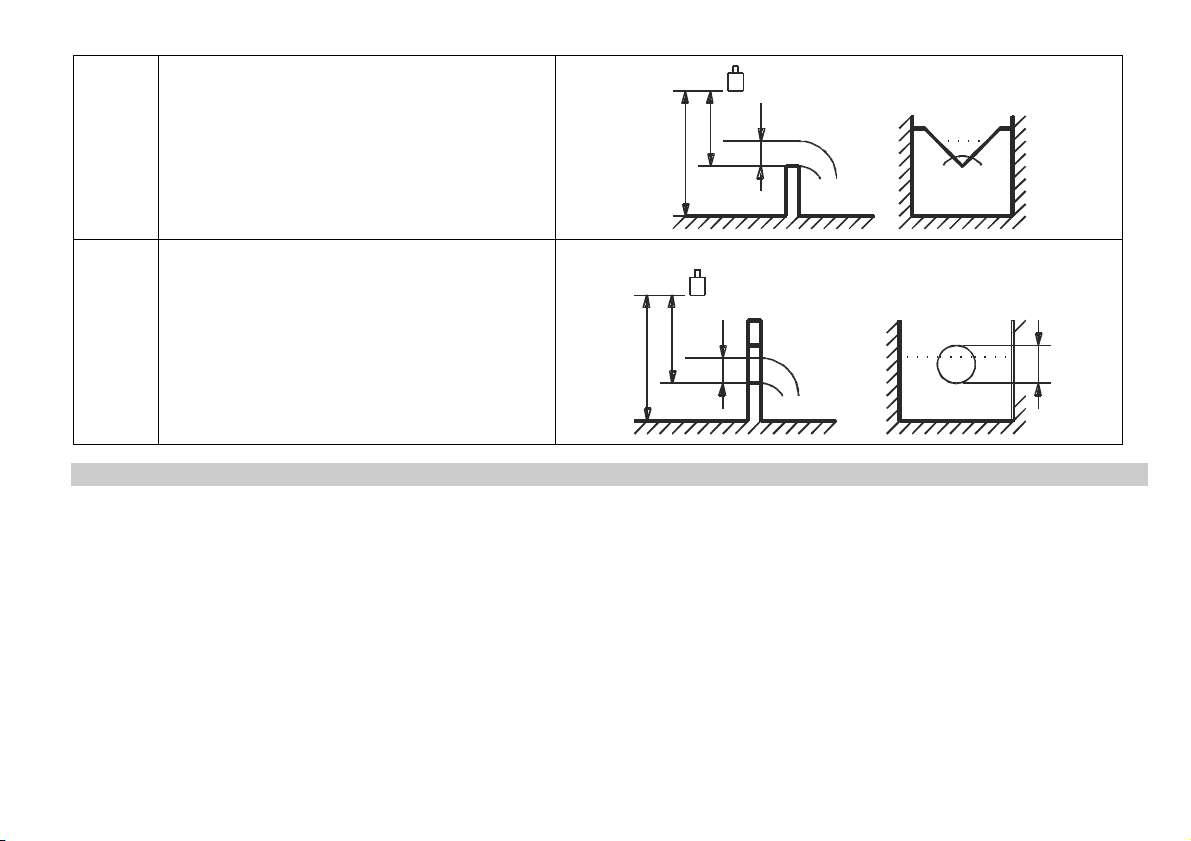
P40=19
P40=20
THOMSON (90°-notch) weir
0.0002 < Q [m3/s] < 1
0.05 < h [m] < 1
3
Q[m
/s] = 1.320 h
Accuracy:
3%
2.47
Circular weir
0.0003 < Q [m
3
/s] < 25
P04
P46
P40=19
h
P40=20
90
0.02 < h [m] < 2
3
Q[m
/s] = m*b D
2.5
. where b = f (h/D)
P04
P46
h
m= 0.555+0.041 h/P41+(P41/(0.11 h))
Accuracy: 5%
P46 - - - - Distance at Q=0 FACTORY DEFAULT: 0
Distance between sensor surface and the level at which flow starts has to be entered in this parameter.
P41
spa5804a0600p_03 33 / 40
Page 34
5.3.8. PROGRAMMING THE VOLUME / MASS / FLOW TABLE (VMFT)
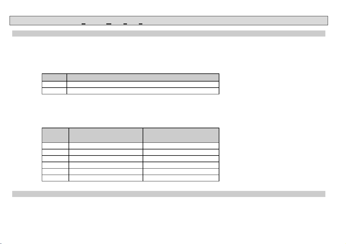
P47: - - - a The operation of VMFT FACTORY DEFAULT: 0
The customer can assign output signals in accordance with optional characteristics to values measured by the transmitter. The characteristic can be
defined with maximum 32 points. Between the points the device will calculate the output signal from the measured value with linear interpolation.
It can be used for example for assigning optional output signal to the measured value or calculating volume from level in case of tank shapes not
included in the selection (e.g. tank with dent).
a
0 doesn’t work
1 works
Conditions of correct programming of the data pairs
The table must always start with L(1)= 0 and r(1)= output value (assigned to 0 level).
The L column can not include identical values.
If the table contains less than 32 data pairs, the L column must be ended with a level value ”0” in the row following the last relevant data pair.
i
L (Left column)
Level values measured
1 0 r(1)
2 L(2) r(2)
L(i) r(i)
nn L(nn) r(nn)
nn+1 0
32
P48: Number of VMFT elements
Shows the number of data pairs entered to VMFT. Read-only parameter.
VMFT mode
r (Right column)
Output value
34 / 40 spa5804a0600p_03
Page 35
5.3.9. INFORMATIONAL PARAMETERS (READ ONLY PARAMETERS)
P60: - - - - Overall operating hours of the unit (h)
P61: - - - - Time elapsed after last switch-on (h)
P62: - - - - Operating hours of the relay (h)
P63: - - - - Number of switching cycles of the relay
P64: - - - - Actual temperature of the transducer (°C / °F)
Broken loop of the thermometer will be indicated by display of the Pt Error message initiated by a signal sent via HART. In this case the transmitter
will perform temperature correction corresponding to 20 ºC.
P65: - - - - Maximum temperature of the transducer (°C / °F)
P66: - - - - Minimum temperature of the transducer (°C / °F)
P70: - - - - Number of Echoes / Echo Map
Amplitude and position of the echoes can also be read out.
P71: - - - - Distance of the of Measuring Window
P72 - - - - Amplitude of the selected echo [dB] <0
P73: Position of the selected echo (time) :(ms)ms
P74: Signal To Noise Ratio
Ratio Measurement conditions
Over 70 Excellent
Between 70 and 30 Good
Under 30 Unreliable
P75: - - - - Blocking Distance
The actual close-end blocking distance will be displayed (provided automatic blocking was selected in P05).
spa5804a0600p_03 35 / 40
Page 36
5.3.10. ADDITIONAL PARAMETERS OF THE FLOW METERING
P76: - - - - Head of flow (LEV) (Read only parameter)
The Headwater value can be checked here. This is the “h” value in the formula for flow calculation.
P77: - - - - TOT1 volume flow totalised (resettable)
P78: - - - - TOT2 volume flow totalised (non-resettable)
5.3.11. OTHER PARAMETERS
P96: - - - - Software code 1 (Read only parameter)
P97: - - - - Software code 2 (Read only parameter)
P98: - - - - Hardware code (Read only parameter)
P99: - - - - Access lock by secret code
The purpose of this feature is to provide protection against accidental programming or intentional reprogramming of parameters by a person not entitled to do so.
The secret code can be any value other than 0000. Setting a secret code will automatically be activated when the EasyTREK is returned to the Measurement
Mode. In order to program locked device the secret code should be entered first in P99. Thus for entering a new code or erasing the old one the knowledge of the
previous code is necessary.
36 / 40 spa5804a0600p_03
Page 37
6. MAINTENANCE AND REPAIR
EasyTREK SP units do not require maintenance on a regular basis. The need for cleaning of the sensor head may occur. Cleaning should be performed by utmost
care where scraping or denting of the transducer have to be avoided. Repair under or after the guarantee period should only be carried out by Nivelco. Devices for
repair should only be returned duly cleaned and disinfected.
6.1. FIRMWARE UPGRADE
Based on the observations & needs of our customers NIVELCO constantly improves and revises the operating software of the device. The software can be
upgraded with the help of the IrDA communication port of the device. For more information about software updates please contact NIVELCO.
7. ERROR CODES
Error Code Error description Causes and solutions
1 Memory error Contact local agent
No Echo Echo loss See Action 5 and 6
3 Hardware error Contact local agent
4 Display overflow Check settings
5
6 The measurement is at the reliability threshold Better location should be found.
7
12
13 Linearisation table error: same L(i) data is given twice in the table See ”Linearisation” Section
14 Linearisation table error: the r(i) values are not monotone increasing See ”Linearisation” Section”
15
16 The check sum of the program is wrong Contact local agent
17 Parameter consistency failure Check programming
18 Hardware failure Contact local agent
Sensor error or improper installation/mounting, level in the dead band Verify sensor for correct operation and check for correct
mounting according to the User’s Manual
No signal received within the measuring range specified in P04 and P05
Linearisation table error: both L(1) and L(2) are zero
Check programming, also look for installation mistake
See ”Linearisation” Section
(no valid data-pairs)
Linearisation table error: measured Level is higher than the last Volume
See ”Linearisation” Section”
or Flow data-pair
spa5804a0600p_03 37 / 40
Page 38
8. PARAMETER TABLE
Par. Page Description Value Par. Page Description Value
d c b a d c b a
P00 13 Application / Engineering Units P28 25 Echo loss indication
P01 14 Measurement Mode P29 26 Blocking out a disturbing object
P02 16 Calculation units P30 –
P03 16 Temperature compensation P31 26 Sound velocity values in different gases
P04 17 Maximum Measuring Distance P32 26 Specific gravity
P05 18 Minimum Measuring Distance P33 –
P06 19 Far End Blocking P40 27 Selection of tank shape / open channel
P07 19 Manual temperature compensation P41 27 Dimensions of tank / Open Channel
P08 20 Fixed current output P42 27 Dimensions of tank / Open Channel
P09 – P43 27 Dimensions of tank / Open Channel
P10 20 Transmitted value assigned to “4 mA” P44 27 Dimensions of tank / Open Channel
P11 20 Transmitted value assigned to “20 mA” P45 27 Dimensions of tank / Open Channel
P12 21 Current output mode P46 33 Level pertaining to flow Q=0
P13 22 Relay function P47 34 VMF Table
P14 22 Relay parameter – Operating value P48 34 Number of VMFT elements
P15 22 Relay parameter – Releasing value P49 –
P16 – P50 –
P17 22 Relay parameter – Pulse rate P51 –
P18 – P52 –
P19 23 Short address of the unit P53 –
P20 23 Damping P54 –
P21 – P55 –
P22 23 Dome top tank compensation
P23 –
P24 23 Target tracking speed
P25 24 Selection of Echo in the measuring window
P26 24 Level elevation rate
P27 24 Level descent rate
38 / 40 spa5804a0600p_03
Page 39
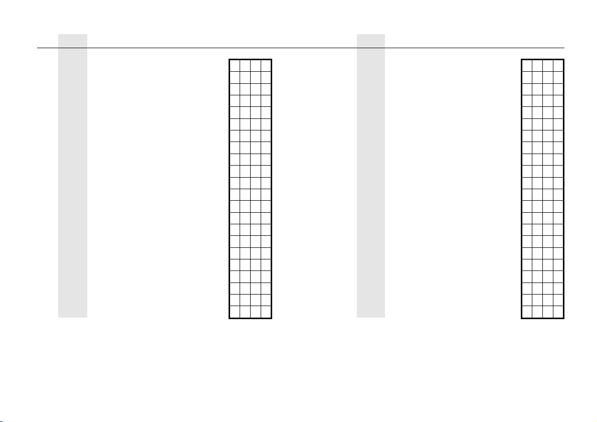
Page Description Value
Par.
Par.
Page
d c b a d c b a
P56 – P78 36 TOT2 volume flow totalised
P57 – P79 –
P58 – P80
P59 – P81 –
P60 35
P61 35
Overall operating hours of the unit
Time elapsed after last switch-on
P82 –
P83 –
P62 35 Operating hours of the relay P84
P63 35 Number of switching cycles of the relay P85
P64 35 Actual temperature of the transducer P86
P65 35 Maximum temperature of the transducer P87 –
P66 35 Minimum temperature of the transducer P88 –
P67 – P89 –
P68 – P90 –
P69 – P91 –
P70 35 Echo Map P92 –
P71 35 Position of the measuring window P93 –
P72 35 Amplitude of the selected echo P94 –
P73 35 Position of the selected echo P95 –
P74 35 Signal / noise ratio P96 36 Software code 1
P75 35 Blocking distance value P97 36 Software code 2
P76 36 Water head of the flow P98 36 Hardware code
P77 36 TOT1 volume flow totalised P99 36 Access lock by secret code
–
–
–
–
Description Value
spa5804a0600p_03 39 / 40
Page 40
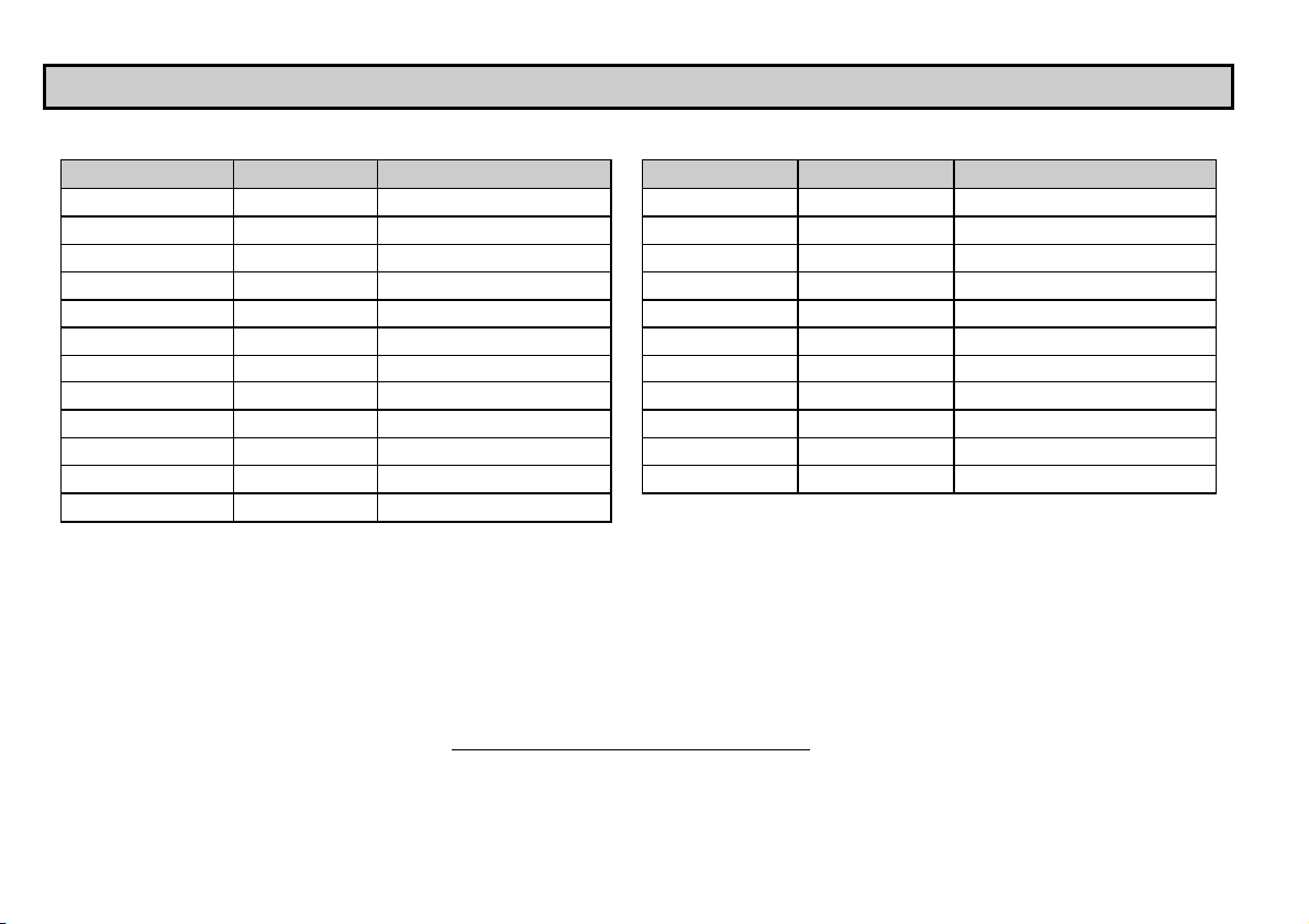
9. SOUND VELOCITY VALUES IN DIFFERENT GASES
The following table contains the sound velocity values of various gases measured at 20 °C.
Gases Formula Sound Velocity (m/s) Gases Formula Sound Velocity (m/s)
O
Acetaldehyde
Acetylene
Ammonia
Argon
Benzene
Carbon dioxide
Carbon monoxide
Carbon tetrachloride
Chlorine
Dimethyl ether
Ethane
Sulphur hexafluoride
C
2H4
C
2H2
NH
3
Ar 319.1
C
6H6
CO
2
CO 349.2
CCl
4
Cl
2
CH
OCH3
3
C
2H6
SF6
NIVELCO reserves the right to change technical specifications without notice.
252.8
340.8
429.9
Ethanol
Ethylene
Helium
Hydrogen sulphide
183.4 Methane
268.3
Methanol
Neon
150.2
212.7
213.4
327.4
Nitrogen
Nitrogen monoxide
Oxygen
Propane
137.8
spa5804a0600p_03
December, 2017
C2H3OH
C2H4
267.3
329.4
He 994.5
H
S
2
CH4
CH3OH
321.1
445.5
347
Ne 449.6
N2
349.1
NO 346
O
2
C
3H8
328.6
246.5
40 / 40 spa5804a0600p_03
 Loading...