

Page 1

BKI 11 ATEX 0017 prw2101a0600p_01 1 / 105
Manufacturer:
H-1043 Budapest, Dugonics u. 11.
Tel.: (36-1) 889-0100 Fax: (36-1) 889-0200
sales
NIVELCO Process Control Co.
E-mail: @nivelco.com www.nivelco.com
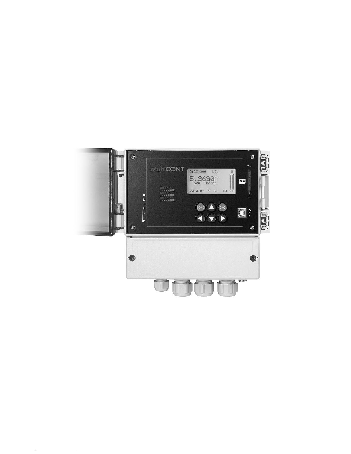
MultiCONT
Page 2
prw2101a0600p_01 2 / 105
Page 3

prw2101a0600p_01 3 / 105
TABLE OF CONTENTS
1. INTRODUCTION.............................................................................................. 5
1.1. THE HART SYSTEM .................................................................................. 6
1.1.1. The Communication ..........................................................................................6
1.1.2. The structure of the system............................................................................... 6
1.1.2.1 Point-to-point connection ......................................................................7
1.1.2.2 Multipoint connection (Multidrop). Multiple slaves connected in parallel.8
1.1.3. Properties of HART-capable devices ................................................................ 9
1.1.4. HART Command set .........................................................................................9
1.1.4.1 Universal commands .......................................................................... 10
1.1.4.2 General commands............................................................................. 11
1.1.4.3 Device –specific commands ............................................................... 11
2. TECHNICAL DATA........................................................................................ 12
2.1. ACCESSORIES......................................................................................... 13
3. ORDER CODE ............................................................................................... 14
3.1. DIMENSIONS............................................................................................ 15
3.2. CONDITIONS OF USE OF THE EX UNITS ....................................................... 16
4. ELECTRICAL CONNECTION ....................................................................... 17
4.1. ARRANGEMENT OF THE CABLE TERMINALS ............................................... 17
4.1.1. Four relays version.......................................................................................... 17
4.1.2. Five relays version .......................................................................................... 17
4.2. WIRING................................................................................................... 19
4.2.1. Wiring .............................................................................................................. 19
4.2.1.1 Wiring of 2-wire units (transmitters) ....................................................19
4.2.1.2 Wiring of 4-wire units (transmitters with separate power supply)........ 20
4.2.1.3 Wiring of Combined Systems (containing both 2- and 4-wire
transmitters) ....................................................................................................... 21
4.2.2. Wiring of Universal Interface Modules (PJK-100)............................................ 22
5. PROGRAMMING OF MultiCONT.................................................................. 23
5.1. STEPS OF PROGRAMMING......................................................................... 24
5.1.1. Scrolling and selecting menu items................................................................. 25
5.1.2. Activation (of devices, relays and current outputs) selection (of language,
operation mode, etc.) ...................................................................................... 26
5.1.3. Assignment of outputs (relay and current) to the device .................................27
5.1.4. Entering parameter values ..............................................................................28
5.1.5. Editing character variables (e.g. Short TAG)................................................... 29
5.2. STEPS OF PUTTING INTO OPERATION A MultiCONT NETWORK................... 29
5.2.1. Preparation of the Transmitters and the Universal Interface Modules. ............30
5.2.1.1 Preparation of the Transmitters...........................................................30
5.2.1.2 Preparing of the Universal Interface Modules......................................31
5.2.2. Wiring...............................................................................................................31
5.2.3. Putting the MultiCONT into operation ..............................................................32
5.3. MAIN MENU............................................................................................. 33
5.4. MultiCONT CONFIGURATION................................................................... 34
5.4.1. DEV detect:......................................................................................................35
5.4.2. EXT detect: ......................................................................................................40
5.4.3. Main Display: ...................................................................................................40
5.4.3.1 Source .................................................................................................41
5.4.3.2 Rounding .............................................................................................42
5.4.3.3 Stepping ..............................................................................................42
5.4.4. List display .......................................................................................................43
5.4.5. User Display:....................................................................................................44
5.4.5.1 Editing the user display .......................................................................44
5.4.5.2 The resulted user displays...................................................................45
5.4.6. HART ...............................................................................................................46
5.4.6.1 MultiCONT Short TAG.........................................................................46
5.4.6.2 Polling Address....................................................................................47
5.4.6.3 Message..............................................................................................47
5.4.6.4 Description...........................................................................................47
5.4.6.5 Date.....................................................................................................48
5.4.6.6 Command Set......................................................................................48
5.4.7. USER RS485...................................................................................................51
5.4.8. Data Logger .....................................................................................................51
5.4.8.1 Trend logger ........................................................................................53
5.4.8.2 Time-window TOT (Total flow logging)................................................55
5.4.8.3 Time-window FM (Flow Maximum logging) .........................................55
5.4.8.4 Using a memory card for logging.........................................................56
5.4.8.5 File system of the SD card and file content of a logging entry.............58
5.4.9. Secret code......................................................................................................62
5.4.10. Language.........................................................................................................63
5.4.11. Background lighting.........................................................................................63
5.4.12. Report:.............................................................................................................64
Page 4

prw2101a0600p_01 4 / 105
5.4.13.
Prog CS........................................................................................................... 64
5.5. PROGRAMMING DEVICES.......................................................................... 65
5.6. REMOTE PROGRAMMING .......................................................................... 66
5.6.1. Editing the linearisation table .......................................................................... 68
5.7. RELAY CONFIGURATION........................................................................... 69
5.7.1. Relay Selection ............................................................................................... 69
5.7.2. Properties of the selected relay....................................................................... 70
5.7.3. Relay programming......................................................................................... 71
5.7.3.1 Source selection ................................................................................. 71
5.7.3.2 Function.............................................................................................. 72
5.7.3.3 Configuring parameters ...................................................................... 80
5.7.3.4 Invert................................................................................................... 81
5.7.3.5 Deleting TOT ...................................................................................... 81
5.7.3.6 Refreshing TOT .................................................................................. 82
5.7.3.7 Testing................................................................................................ 82
5.8. OPERATION AND PARAMETERS OF CURRENT OUTPUTS .............................. 84
5.8.1. Selection of Current outputs............................................................................ 84
5.8.2. Properties of the selected Current Output....................................................... 85
5.8.3. Current Output programming .......................................................................... 85
5.8.3.1 Source selection ................................................................................. 85
5.8.3.2 Function.............................................................................................. 86
5.8.3.3 Parameter configuration ..................................................................... 87
5.8.3.4 Testing................................................................................................ 87
5.9. THE BOOT PROCESS ............................................................................... 88
5.10. MEASUREMENT MODES ........................................................................... 90
5.11. SAVING, LOADING THE CONFIGURATION OF THE MULTICONT ..................... 91
6. ERROR CODES............................................................................................. 92
7. HARDWARE PROTECTION OF THE SETTINGS ........................................ 94
8. FUSE REPLACEMENT ................................................................................. 95
9. SERVICING.................................................................................................... 96
9.1. BOX MESSAGES:..................................................................................... 96
9.2. OTHER MESSAGES:................................................................................. 97
9.3. TROUBLESHOOTING................................................................................. 98
9.3.1. It is impossible to enter the „Main menu”/”Relays” or „Main menu”/„Current
outputs” menu: ................................................................................................ 98
9.3.2. It is impossible to enter the „Main menu”/”Devices” menu: ............................. 98
9.3.3. A „Please wait” message appears upon selecting „DEV detect”.................... 98
9.3.4. The result of „DEV detect” is the „No device” message .................................. 98
9.3.5. The unit does not start up when switched on ..................................................98
9.3.6. The „Response” error entry is too frequent...................................................... 98
9.4. ADDITIONAL INFORMATION ........................................................................99
9.4.1. Problems that may occur during remote programming:................................... 99
9.4.2. MultiCONT transmits the parameters without examining them, and the testing is
done by the device...........................................................................................99
9.4.3. Use of Second HART Master ( Hand-Held or HART modem + Eview
configuration software) ....................................................................................99
9.4.4. Upon exiting remote programming, the unit tests to see if the transmitter really
exited the remote programming mode............................................................. 99
9.4.5. When a transmitter does not respond, then „Response” error is entered into the
table, but upon termination of the error (the device responds), this entry is
automatically cleared from the table (and does not need to be acknowledged)99
9.4.6. Upon exiting the menu, MultiCONT immediately saves the modifications.......99
9.4.7. The error list is cleared when the device is put off........................................... 99
Appendix 1. ManufacturerID codes of HART-capable devices 100
Appendix 2. The menu system of the MultiCONT P-200 101-102
Appendix 3. Relay programming 103
Appendix 4. Current output programming 104
Appendix 5. Measurement mode 105
Page 5
prw2101a0600p_01
5 / 105
Thank you for choosing a NIVELCO instrument.
We are sure that you will be satisfied throughout its use!
1. INTRODUCTION
The MultiCONT unit is a universal interface between NIVELCO’s HART-capable intelligent level transmitters and the other elements of the process control system
like the PC-s , PLC-s, displays and the actuators. Besides its role as an interface, the MultiCONT ensures the powering of the 2-wire transmitters while being capable
of complex control tasks. The MultiCONT unit supports communication with a maximum of 15 standard or 4 Ex certified NIVELCO’s HART-capable 2- and / or 4-wire
transmitters. If MultiCONT is used with NIVELCO’s MicroTREK microwave level transmitters the maximum number of transmitters in a loop should not exceed 8 pcs.
for normal transmitters and 2 pcs. for Ex version transmitters. If a system contain more transmitters than one MultiCONT can handle, further MultiCONT units can be
wired in series via an RS485 line. Remote programming of the transmitters and downloading of the parameters and measured data is possible using the MultiCONT.
The various outputs such as 4 … 20 mA, relays and digital outputs can be controlled using measured values and new values calculated from the measured values.
Measured values (Primary Value and three additional values) are able to be logged.
Large DOT matrix LCD panel facilitate a wide variety of display functions including tank content visualisation. The type and number of outputs of the basic unit can be
expanded with external (relay and/or current output) PJK-100 type Universal Interface Modules. The total number of relays included in the MultiCONT and in the
modules must not be more than 64, while that of the analog outputs (4…20 mA outputs) can be maximum 16. A further restriction is that there can be a maximum of
32 Universal Interface Modules.
Explosion proof certified versions of the MultiCONT should be installed outside the hazardous area.
Page 6
prw2101a0600p_01 6 / 105
1.1. THE HART SYSTEM
The HART (Highway Addressable Remote Transducer – bus addressable field devices) is a digital communication protocol developed by ROSEMOUNT for industrial
measurement applications. A digital signal of small amplitude is placed on the widely used standard 4…20mA output current, and due to its symmetric sinusoidal
nature and its small amplitude, it does not affect the accuracy of the output current. Since no extra cable is needed for signal transfer, the already existing cable can
be used to realize the transfer. The identification, programming and querying of the transmitters can be done using this communication.
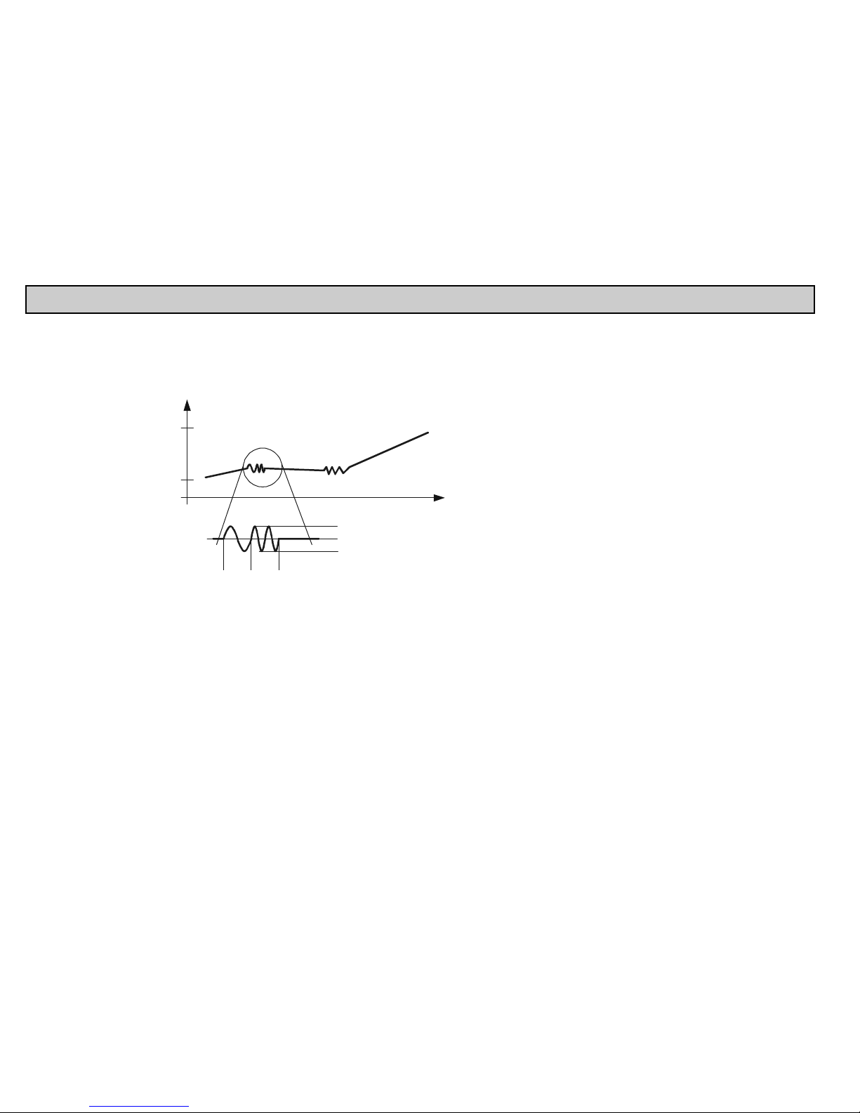
This diagram shows the output signal of a
4…20mA transmitter (device) and the
superimposed HART signal, which is essentially a
0.5 mA modulation of the output current..
t
I
out
[mA]
20 mA
4 mA
1
Io + 0.5 mA
I
o
Io – 0.5 mA
0
The enlarged picture shows that HART
communication uses frequency modulation, and
logical „1” is assigned to 1200 Hz, while „0” is
assigned to 2200 Hz. This is called FSK
(Frequency-Shift Keying) modulation. The
communication is realized with systematic series
of impulses above described.
1.1.1. The Communication
The HART communication is basically a master-slave type, which means that the transmitter – slave – only sends a response when the master (of which there can be
only one in the system) sends a query. The master can be a Hand-held Communicator, a PC with a HART modem or a universal interface, in this case, a MultiCONT
(naturally, only one can be active). The communication uses standard commands (see chapter 1.1.3)
1.1.2. The structure of the system
The system must contain a 230..1000 resistor to guarantee that the HART signal of small amplitude will not load the power supply of unknown output impedance.
Page 7
prw2101a0600p_01
7 / 105
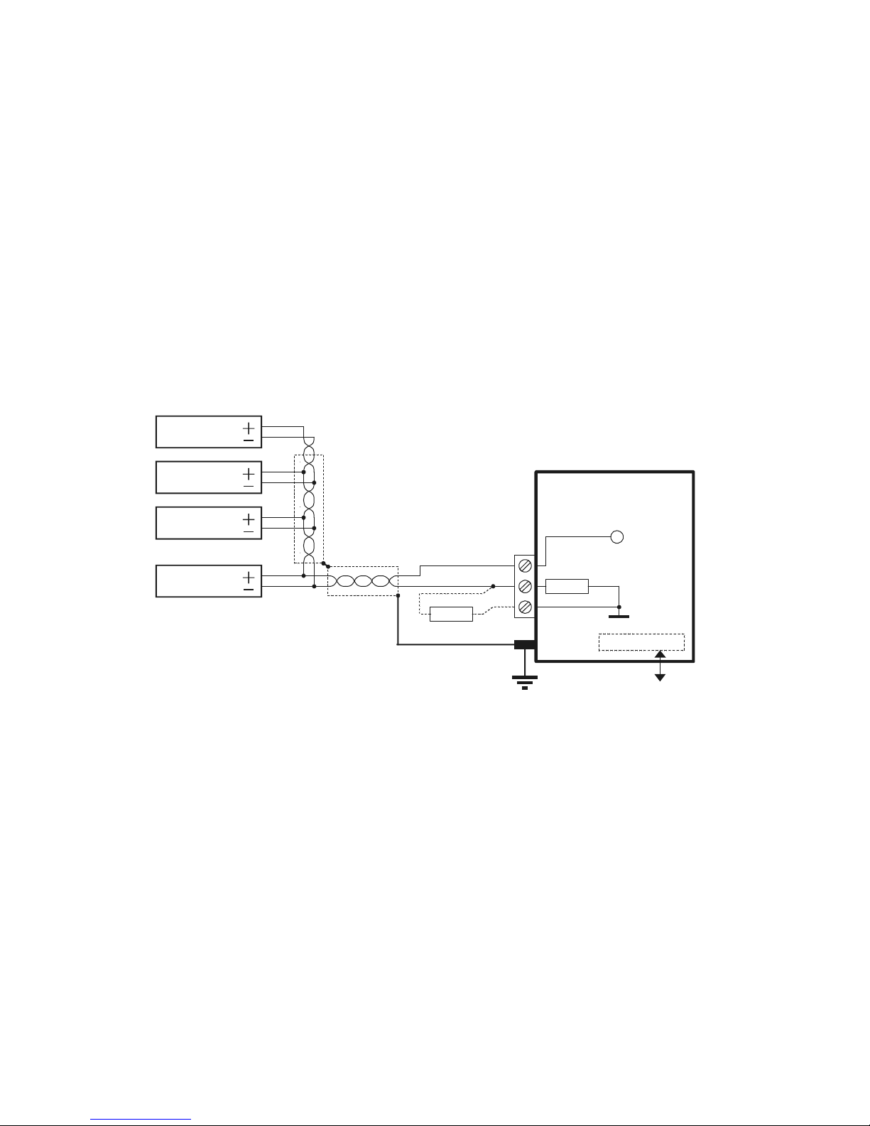
1.1.2.1 Point-to-point connection
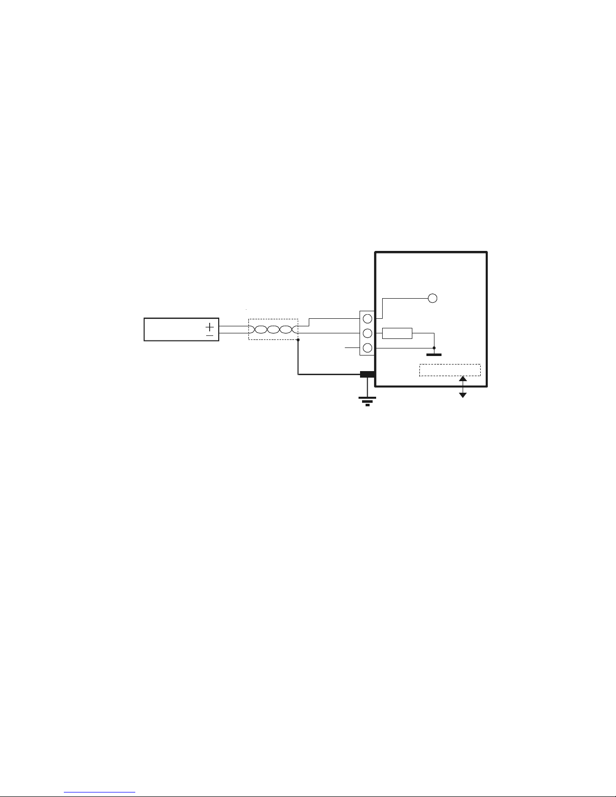
When a master (communicator or HART modem with PC or MultiCONT) and a slave are alone in a system, we talk of a point-to-point connection
Transmitter
I+
I–
SH
L+
L–
MultiCONT
250
+U
s
Universal interface
RS485
In this case the flowing current is the output current of the transmitters, so if permitted by the loop voltage, even a local indicator can be included into the loop.
Essentially, the minimal voltage specified in the manual must be kept on the terminals of the transmitters.
Since the speed of transfer is 1200bit/sec, communication is slow, because the master queries and the slave responds. This can be speeded up if the querying is left
out, and the slave responds continuously every given period of time until the master stops the transfer in the break between 2 data transmissions. This is called “burst
mode”.
Page 8
prw2101a0600p_01 8 / 105
1.1.2.2 Multipoint connection (Multidrop). Multiple slaves connected in parallel.
HART’s addressing system can handle 15 devices whereby they are wired in parallel. In this case, the current is the sum of the currents of all the devices in the loop,
which has not informative value. So in this case, the output current of the transmitters should be set to multidrop mode, which means a constant current of 4mA. This
automatically happens when the polling address is set between 1..15. (if the polling address is 0, then we should have only one transmitter with 4…20mA output, if
the polling address is 1…15, then we will have a constant 4 mA). There is a deviation possibility for transmitters whose output current can be programmed to an
arbitrary fixed value, however in this case, the minimal voltage drop on the terminal of the transmitters must be the minimum specified voltage, otherwise the
transmitter(s) will not be able to work (measure or respond)
T 1ransmitter
Transmitter 2
T 3ransmitter
T 15ransmitter
I+
I–
SH
L+
L–
MultiCONT
250
+U
s
....
Universal interface
RS485
820 *
In a Multidrop system, the „burst mode” does not work
* An 820 ohm resistor should be connected between the L- and SH terminals of the Ex version MultiCONT when it is used with the 3 (max. allowed) Ex version
MicroTREK microwave level transmitter.
Page 9

prw2101a0600p_01
9 / 105
1.1.3. Properties of HART-capable devices
These are programmed into the unit during manufacturing, some can be configured using a HART MASTER, others cannot (they can be reconfigured only by the
manufacturer)
Short TAG 8 character device ID. Can be reconfigured.
Short address Used to differentiate the 0…15 devices. There cannot be 2 identical „short addresses” in one system. Can be reconfigured
Message A max 32-character arbitrary comment that can be assigned to the device and is generally operation-related.
Can be reconfigured
Descriptor A max 16-character arbitrary comment that can be assigned to the device and is generally material-related.
Can be reconfigured
Date Date. Can be assigned to the device. Can be reconfigured
Factory ID Factory ID. For NIVELCO devices: 151, cannot be reconfigured
Device type ID Device type ID, cannot be reconfigured
Device ID The manufacturer’s electronic production number, cannot be reconfigured
The Factory ID, the Device Type ID and the Device ID together form the “Long Address”.
SW version ( Software version ): Software version of the device (see device manual)
HW version ( Hardware version ): Hardware version of the device (see device manual)
Apart from this, they provide the specification of the HART version according to which the device’s commands work
1.1.4. HART Command set
We have seen how to build up a HART system. Using the HART commands, we can decide what the devices should do. Naturally, an ultrasonic transmitter needs
commands different from those of a temperature transmitter or maybe a valve, so quite a large number of commands would be needed. Every command has a onebyte identifier. The 31
st
command enables expansion, and in this case the next 2 bytes form the code of a command (0…65535). HART commands can be divided in
to 3 classes:
universal commands 0..30
general commands 32..121
device-specific commands 128..253
In all cases, the commands contain an address (this can be short, long address, TAG), which determines the corresponding device.
Two devices with the same address cannot be connected together!!
Page 10

prw2101a0600p_01 10 / 105
1.1.4.1 Universal commands
These are commands understood by all devices, and to which all devices give the same reply.
0. Read unique identifier
the addressed device provides the following in it’s reply:
Manufacturer’s code (provided by the HART foundation, see appendix)
Product code (provided by manufacturer, see chapter 5.2.1.1)
Universal command table code ( HART 5 )
Device ID
Software version
Hardware version
Device status
1. Read primary variable
This reads the digital value (Primary Value) that the transmitter sends to the 4…20 mA output.
The unit also belongs to the numeric value.
2. Read output current in mA and in percent of range
3. Read output current and four dynamic variables
The primary, secondary, tertiary and quaternary variables are transmitted.
The secondary, tertiary and quaternary variables are specified in the manual of the given device.
6. Modify (short) polling address (Write polling address)
If there is more than one device in the loop (multidrop), each device must have a different address.
In this case, the address should be configured before connecting the device to avoid errors caused by devices with the same addresses replying at the same
time.
11. Read unique device identifier associated with tag
Devices are queried based on their short TAG and not based on their addresses.
As a result, there must not be more than one device with exactly the same short TAG.
Page 11

prw2101a0600p_01
11 / 105
12. Read device message
This reads the 32 character message stored in the non-volatile memory of the device (e.g. T18 35% HCL TANK)
13. Read the 8 character ”short TAG”, 16 character descriptor and date
14. Read PV sensor information
15. Read output information
16. Read final assembly number
17. Write 32 character message
18. Write the 8 character ”short TAG”, 16 character descriptor and date
19. Write final assembly number
1.1.4.2 General commands
These commands do not need to be understood by all devices. If not understood, nothing happpens, however, if understood, then it must be interpreted according to
the standard. Many such commands exist, the most important ones are the following:
34: damping (writing settling time)
35: measurement range (writing of upper and lower limits, and/or dimension)
36: Upper limit now! (sets the upper limit – 20 mA)
37: Lower limit now! (sets the lower limit – 4 mA)
40: setting constant current output (can be very useful during testing)
41: Device self-test, sends back the result.
42: Master reset (setting factory default)
50: Reading assignment status of the primary variable (PV), the secondary variable (SV), the tertiary variable (TV) and the quaternary variable (QV). This can
not always be read unambiguously, in most cases it can be found in the manual of the device.
109: Switching „Burst” mode on and off.
1.1.4.3 Device –specific commands
These commands are specified by the manufacturer. A description of the commands can be found in the device manual.
Page 12
prw2101a0600p_01 12 / 105
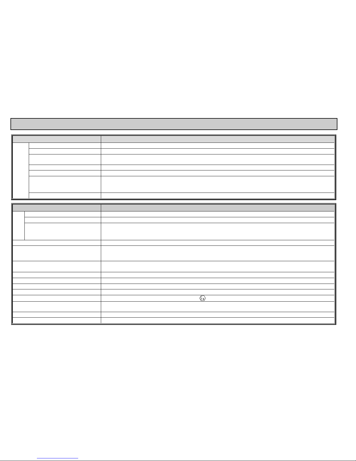
2. TECHNICAL DATA
TYPE P - 2-
Transmitter Power Supply 30 V DC / 60 mA (For Ex Version: 25 V DC / 22 mA)
Display 128 x 64 dot-matrix
Analogue
Max. 2 galvanically isolated 4 … 20 mA outputs,
max load of 500 ohm, with over-voltage protection
Relay Max. 5 SPDT, 250 V AC, AC1. 5 A
RS 485 interface Galvanically isolated, HART / MODBUS protocol
HART
Output signal level: 0.5 ±0.1 V
pp
trapezoid 1200 / 2200 Hz
Minimum level of Input signal: 50 mV
pp
Inbuilt sensor resistance: 250 ohm.
Outputs
Logger Capacity: FLASH = 65000 entry; SD card (max 2 GB) = depends on the card!
TYPE P - 2-
Power Supply, Relays, analogue 4 … 20 mA 0.5 … 2.5 mm2 wire cross-section
RS 485 interface Shielded, twisted cable pair with a cross section of 0.5 … 2.5 mm2
Connecting
cables
HART line
Below1500 m shielded, twisted cable pair with a min.cross section of 0.5mm
Above 1500 m shielded, twisted cable pair, with a min. cross section of 0.8mm
max. resistance : 75 ohm, max.capacitance : 200 nF
Number of powered transmitters Max. 15 non-Ex (max. 4 Ex) transmitters
Power supply /
Power consumption /
max. power supply
85 … 255 V AC 50 … 60 Hz / 12 VA / 255 V
eff
11.4 … 28 V AC 50 … 60 Hz / 12 VA / 28 V
eff
11.4 … 40 V DC / 11 W / 40 V DC
Fuse
85 … 255 V AC 50 … 60 Hz T400 mA
11.4 … 28 V AC 50 … 60 Hz és 11.4 … 40 V DC T1A
Housing material Polycarbonate (PC)
Mounting Wall mounted
Ambient Temperature -20 °C … +50 °C
Ingress protection IP 65
Ex marking
II (1) G [Ex ia Ga] IIB
Intrinsically safe output limitation data
U
o
= 30 V Io = 140 mA Po = 1 W
L
o
= 4 mH Co = 200 nF
Electrical protection Class I / III
Mass 0.9 kg
Page 13

prw2101a0600p_01
13 / 105
2.1. ACCESSORIES
Warranty Card
User’s and Programming manual
Declaration of Conformity
2 universal cable gland sealings
Page 14
prw2101a0600p_01 14 / 105
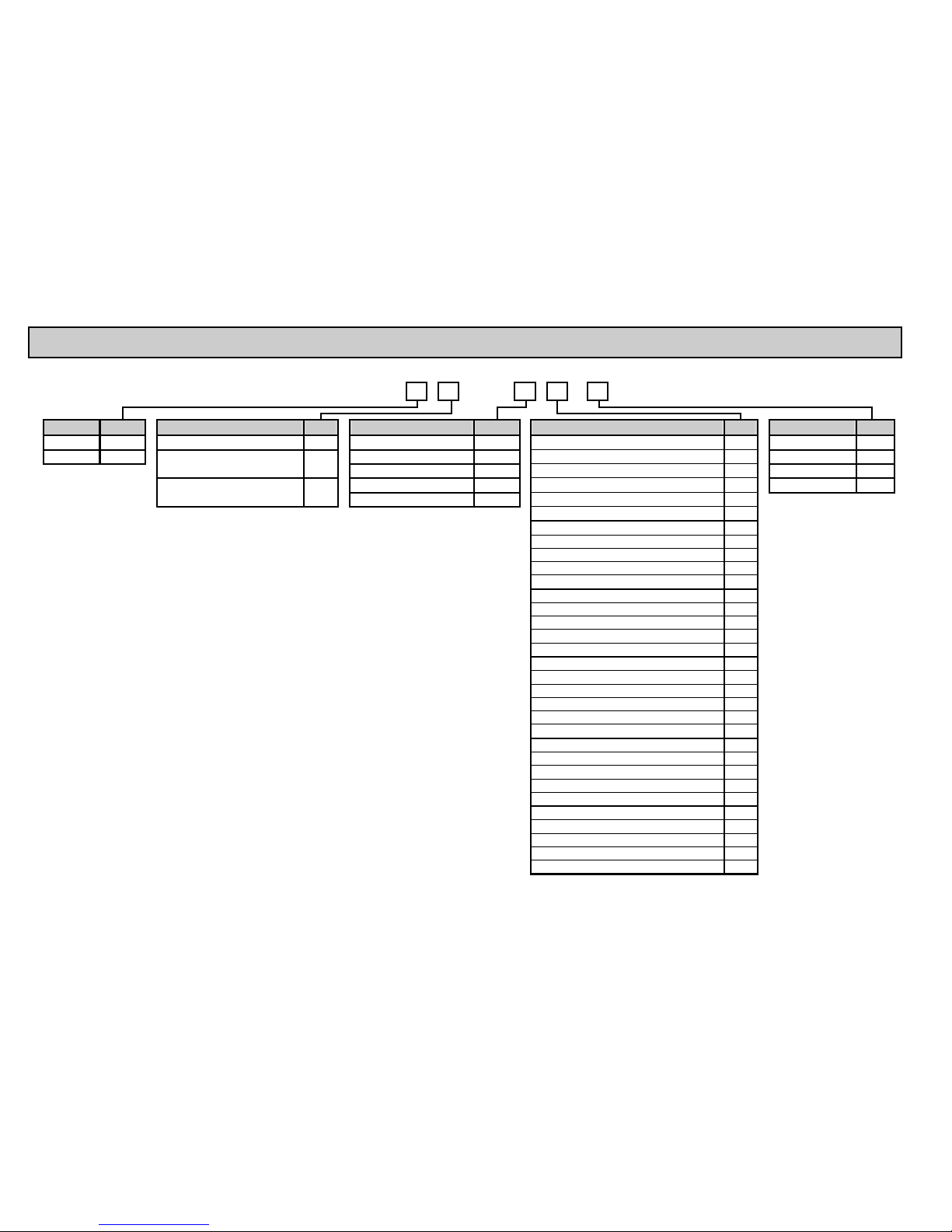
3. ORDER CODE
MultiCONT P – 2 –
EXPANSION CODE ENCLOSURE CODE INPUT CODE OUTPUT CODE POWER SUPPLY CODE
Expandable * R IP 65 wall enclosure W 1 HART unit 1 Display only 0 85 … 255 V AC 1
Standard E 2 HART units 2 1 relay 1 24 V AC / DC 2
IP 65 wall enclosure +
transparent cover
C
4 HART units 4 2 relays 2 85 … 255 V AC Ex 5
8 HART units 8 3 relays 3 24 V AC / DC Ex 6
IP 65 wall enclosure +
transparent cover + logger
D
15 HART units M 4 relays 4
5 relays D Ex: Ex ia
1x 4-20mA Analogue output F
1 relay + 1 x 4-20 mA Analogue output 5
2 relays + 1 x 4-20 mA Analogue output 6
3 relays + 1 x 4-20 mA Analogue output 7
4 relays + 1 x 4-20 mA Analogue output 8
2x 4-20mA Analogue output G
1 relay + 2 x 4-20 mA Analogue output H
2 relays + 2 x 4-20 mA Analogue output J
3 relays + 2 x 4-20 mA Analogue output K
4 relays + 2 x 4-20 mA Analogue output 9
RS 485 interface A
1 relay + RS 485 interface L
2 relays + RS 485 interface M
3 relays + RS 485 interface N
4 relays + RS 485 interface P
5 relays + RS 485 interface E
1x 4-20mA Analogue output + RS 485 interface B
1 relay + 1 x 4-20 mA output+ RS 485 interface R
2 relays + 1 x 4-20 mA output+ RS 485 interface C
3 relays + 1 x 4-20 mA output+ RS 485 interface S
4 relays + 1 x 4-20 mA output+ RS 485 interface T
2x 4-20mA + RS 485 interface U
1 relay + 2 x 4-20 mA output+ RS 485 interface V
2 relays + 2 x 4-20 mA output+ RS 485 interface W
3 relays + 2 x 4-20 mA output+ RS 485 interface X
4 relays + 2 x 4-20 mA output+ RS 485 interface Y
The order code of an Ex version should end in „Ex”.
* The system can be expanded using Relay, Analogue and Universal Interface Modules
Page 15
prw2101a0600p_01
15 / 105
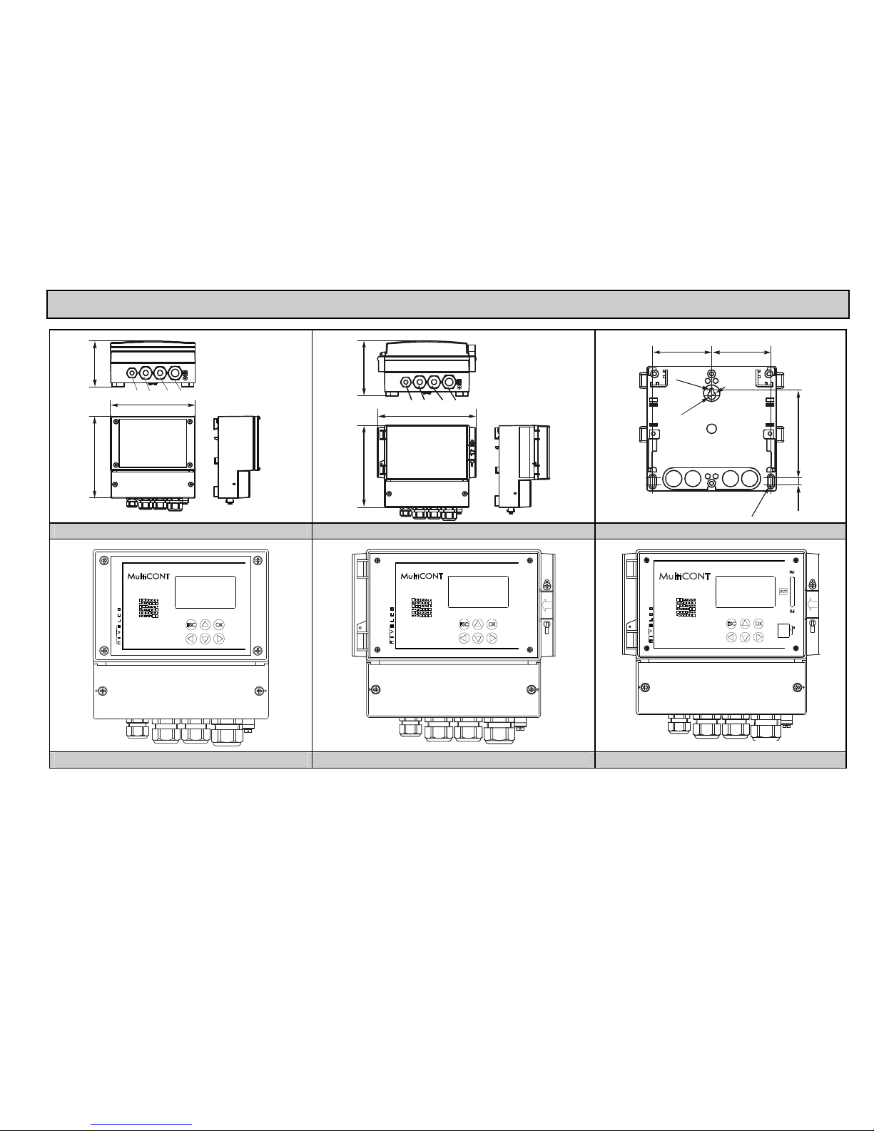
3.1. DIMENSIONS
160
166
89.5
AB BC
A
Pg9 or M16
B Pg11 or M20
C Pg11, Pg13.5 or M20
10716 0
193
A
Pg9 or M1 6
B Pg11 or M20
C Pg11, Pg13.5 or M20
CBB
A
75.575.5
11210
1
0
R
2
.
7
R
2
.
5
PW PC, PD ARRANGEMENT OF MOUNTING HOLES
PW PC PD
Page 16

prw2101a0600p_01 16 / 105
3.2. CONDITIONS OF USE OF THE EX UNITS
The units should be mounted outside the hazardous zone!
Device should be protected against direct sunshine!
The power supply and ambient temperature values must not exceed the specifications in the Technical data!
Transmitters installed in hazardous areas must only be connected to the L+ and L- terminals!
The housing of the transmitter must be grounded!
The transmitters must be connected using shielded, twisted cable pairs!
Page 17
prw2101a0600p_01
17 / 105
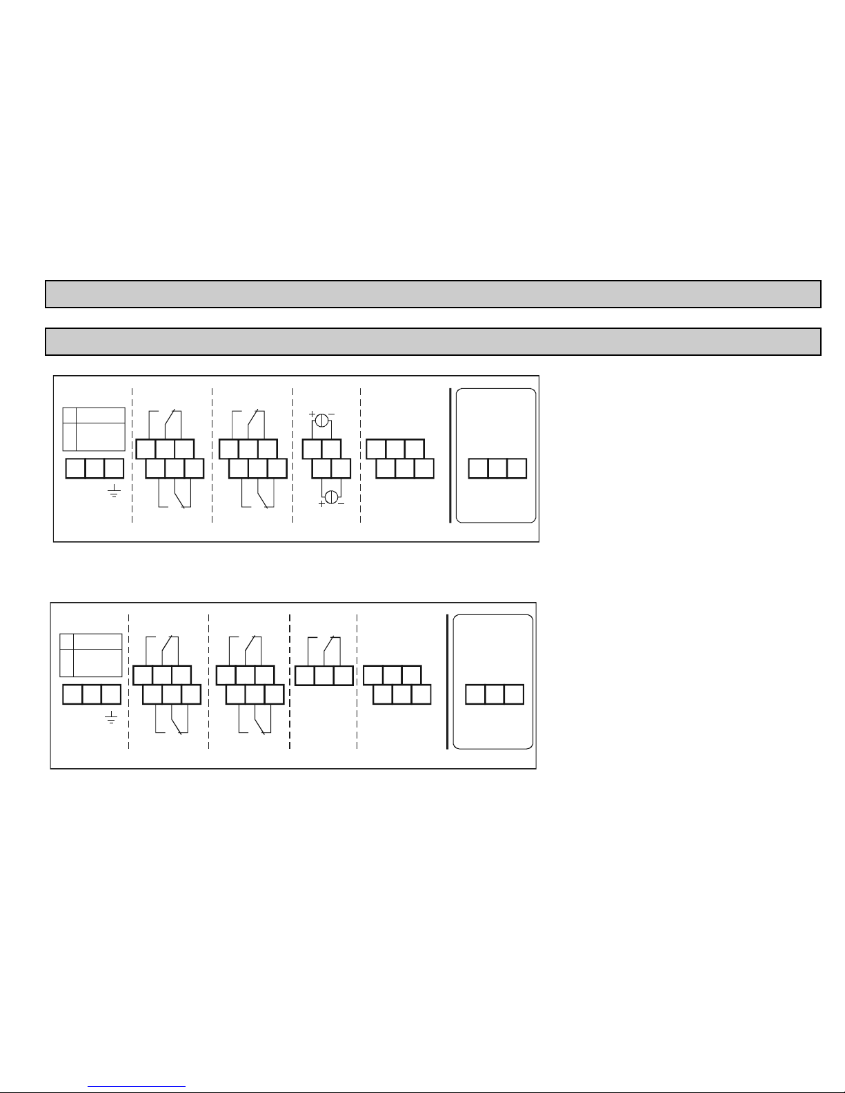
4. ELECTRICAL CONNECTION
4.1. ARRANGEMENT OF THE CABLE TERMINALS
4.1.1. Four relays version
1 2 3
4 5 6
7 8 9
16 17
18 19
10 11 12
13 14 15
20 21 22
23 24 25
MAINS RELAY 1
RELAY 2
RELAY 3
RELAY 4
CURRENT
OUT 1
CURRENT
OUT 2
USER RS485
MODULE RS485
ABCOM
ABCOM
DEVICES
26 27 28
LLSH+
-
11.4 ... 28V
AC
11.4 ... 40V
DC
85 ... 255V
AC
()+-()
**
*
After loosening and removing screws fastening the
cover the cables can be connected. The same cable
should not be used for AC and DC as well as for SELV
and mains voltage.
For wiring of the transmitters shielded, twisted cable
pair (STP) should be used with the length depending
on the number of connected units and the electrical
properties of cable.
RS485 interface: A: TRD+
B: TRD–
COM: shielding
* Only PR types
** Non-Ex versions only
4.1.2. Five relays version
1 2 3
4 5 6
7 8 9
10 11 12
13 14 15
20 21 22
23 24 25
MAINS RELAY 1
RELAY 2
RELAY 3
RELAY 4
RELAY 5
USER RS485
MODULE RS485
ABCOM
ABCOM
DEVICES
26 27 28
LLSH+
-
11.4 ... 28V
AC
11.4 ... 40V
DC
85 ... 255V
AC
()+-()
16 17 18
Page 18
prw2101a0600p_01 18 / 105
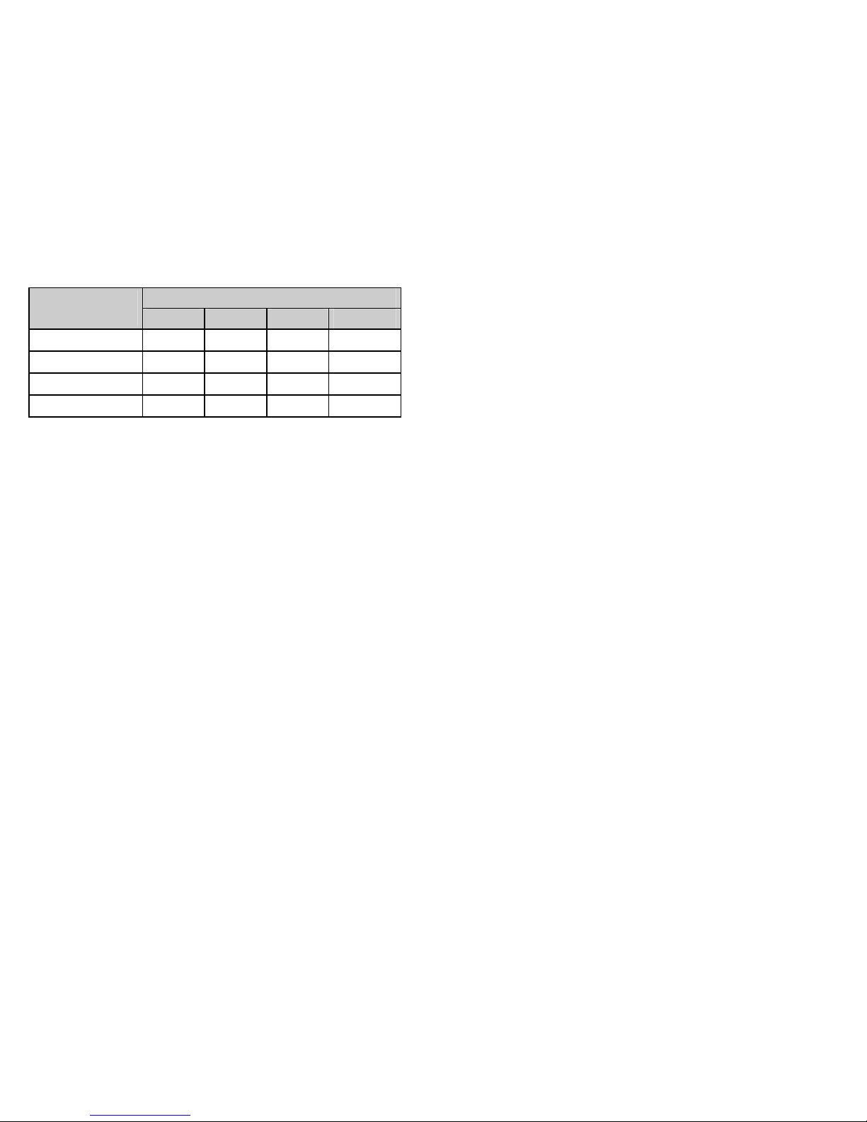
Cabel Capacitance (pF / m)
Number of
Transmitters
65 95 160 225
1 2800 2000 1300 1000
5 2500 1800 1100 900
10 2200 1600 1000 800
15 1850 1400 900 700
Shielding of the connecting cable between the transmitter and the controller should be grounded at one end, connected either to the internal or external part of the
earthing screw.
Intrinsically safe (Ex) transmitters should be connected through the terminals L+, L– to the controller. These points are galvanically isolated from the other parts of the
electronics. Power supply for the Ex transmitter is current-, voltage- and power-limited.
Page 19
prw2101a0600p_01
19 / 105
4.2. WIRING
4.2.1. Wiring
Before wiring, please check: if the units (order codes) are HART-capable, the value of the loop current and also if there are two or more units with the same “Short
address”. (See 5.2. Steps of commissioning)
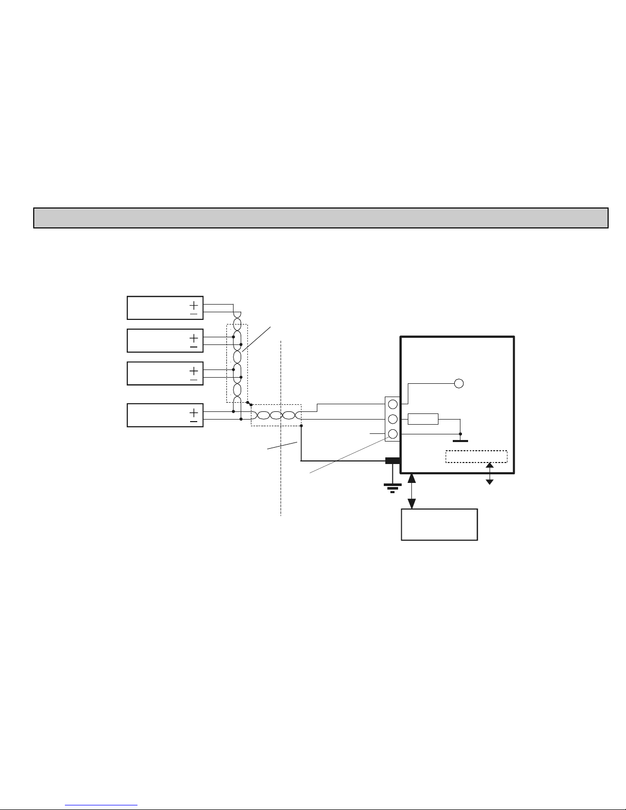
4.2.1.1 Wiring of 2-wire units (transmitters)
Shielding grounded
at the MultiCONT
In non-Ex versions only
Transmitter 1
T 2ransmitter
T 3ransmitter
T Nransmitter
I+
I–
SH
L+
L–
MultiCONT
250
+U
s
Shielded twisted
cable pair
Universal interface
USER
RS485
Non-Ex area
Ex area
PJK-100
Universal interface
modules
MODULE
RS485
Page 20
prw2101a0600p_01 20 / 105
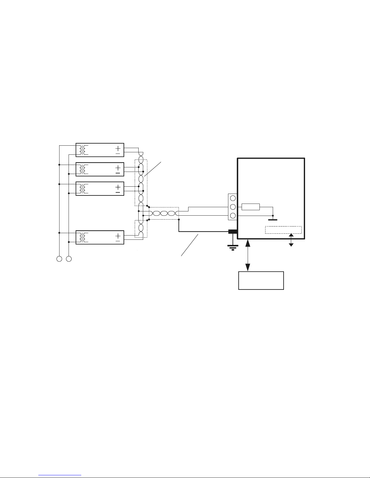
4.2.1.2 Wiring of 4-wire units (transmitters with separate power supply)
85...255 VAC
11.4...28 VAC
11.4...40 VDC
Shielding grounded
at the MultiCONT
I+
I– SH
L–
MultiCONT
250
Transmitter 1
T 2ransmitter
T 3ransmitter
T 15ransmitter
Shielded twisted
cable pair
Universal interface
USER
RS485
MODULE
RS485
PJK-100
Universal Interface
Modules
Page 21
prw2101a0600p_01
21 / 105
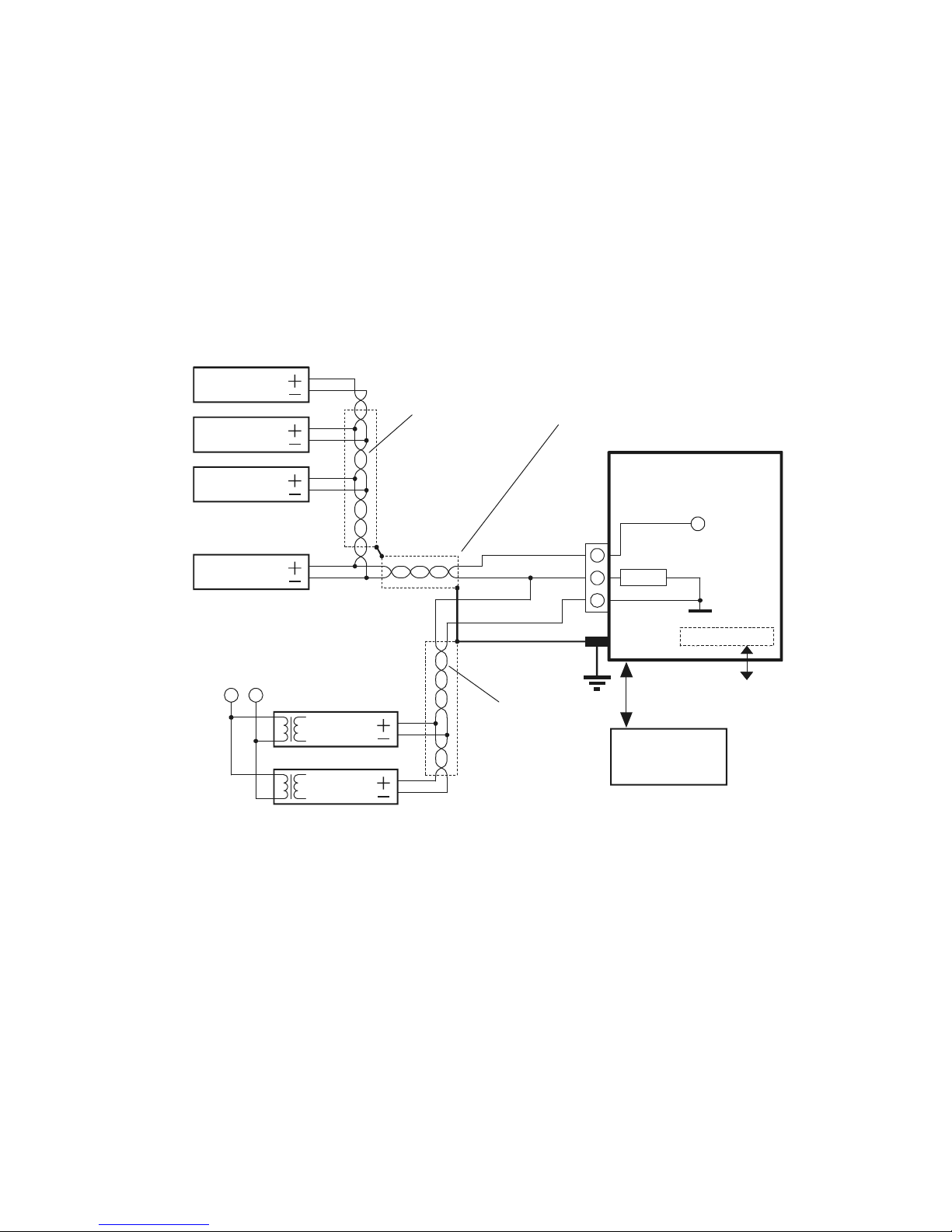
4.2.1.3 Wiring of Combined Systems (containing both 2- and 4-wire transmitters)
Transmitter 1
T Nransmitter
T 1ransmitter
T Mransmitter
85...255 VAC
11.4...28 VAC
11.4...40 VDC
T 2ransmitter
T 3ransmitter
Shielding grounded
at MultiCONT
I+
I–
I+ SH
I–
L+
L–
MultiCONT
250
+U
s
Shielded twisted
cable pair
Shielded twisted
cable pair
Universal interface
USER
RS485
MODULE
RS485
PJK-100
Universal Interface
Modules
Page 22
prw2101a0600p_01 22 / 105
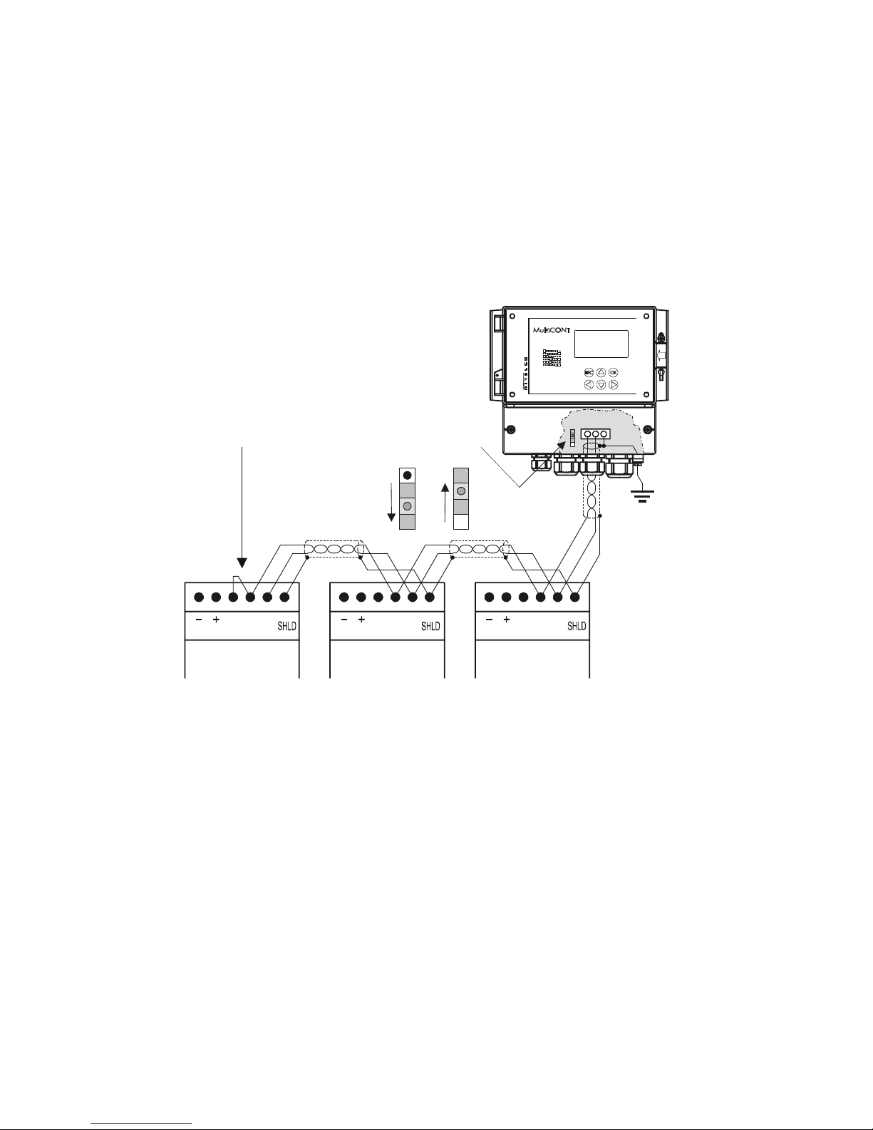
4.2.2. Wiring of Universal Interface Modules (PJK-100)
TB B A
24VDC
TB B A
PJK-102 PJK-120 PJK-111
24VDC
Module RS485
A B COM
K2: terminal resistor
ON
K2
Connection with shielded twisted pair cable, shielding is
grounded at one point, at the MultiCONT.
The terminal resistor is connected to the two farthest points
of the cable. (TB and B terminals are connected in PJK 100;
and on the MultiCONT the K2 terminal resistor, located
next to the terminals, is switched on.)
TB B A
24VDC
OFF
relay module 4-20 mA module relay + 4-20 mA module
The most important rule is that the data transfer line has to be closed at both ends with a resistor, at points farthest from each other. The value of the terminal resistor
depends on the wave impedance of the connecting cable. The interface contains a 120
terminal resistor, so please use a cable with appropriate impedance.
A configuration, whereby there aren’t 2 terminal resistors, or where the 2 terminal resistors are not at the farthest points from each other is a bad configuration.
In such cases, especially if the data transfer cable is too long, data transfer errors are likely to occur.
The Universal Interface Modules should be connected one after another on one cable pair. Star-shaped topology is forbidden. The maximum length of the cable is
1000m, but in this case a cable with shielded, twisted pair of wires (STP, Shilded Twisted Pair) must be used. The capacitance of the cable should be less than
100 pF/m. The Universal Interface Modules connected to a system must each be given different addresses (0…31), see 5.2.1.2.
Page 23

prw2101a0600p_01
23 / 105
5. PROGRAMMING OF MultiCONT
During programming the following can be performed:
Automatic detection of devices (transmitters) connected to the MultiCONT, and putting them into the list of devices. Devices not on the list are part of the
system but are unable to communicate with the MultiCONT (see 5.2.3 Main menu / MultiCONT config / DEV detect).
Activation, inactivation of devices (transmitters) (See 5.2.3 Main menu / Devices).Theoretically all devices in the system should be working. (whether in the
list or not). Devices in the list automatically become active. Inactivation can be used to temporarily disable devices from the system.
Activation, inactivation of relays and current outputs (see Attachment 3 and 4)
Relays and current outputs of the MultiCONT should also be activated (see Attachment 3 and 4)
Assignment of the MultiCONT outputs (relays, current outputs) to devices (transmitters)
Formation of functional values (difference of 2 measured values, sum or average of 2 or more measured values)
Remote programming of devices, although it is practical to program the devices in the laboratory before installation and wiring.
(parameters of the transmitters e.g. P01, P02, etc. will be used in this Manual in the same way as described in the Installation and User’s Manual)
Programming of MultiCONT outputs (Relay and current output parameters of the MultiCONT will be identified as RP1, RP2, RP3 and CR1, CR2, CR3
respectively).
The programming of systems involving the MultiCONT universal interface assumes a sound knowledge of both the HART standard and the programming
of the connected devices.
During programming full scale of operation such as measurement, polling of devices, functioning of the relays and current outputs will be maintained.
Modifications will be automatically saved upon returning back to measurement mode.
If the MultiCONT is left in Programming mode, it will automatically return to Measurement mode 5 minutes after the last key was pressed (modifications
will be saved!).
Page 24
prw2101a0600p_01 24 / 105
5.1. STEPS OF PROGRAMMING
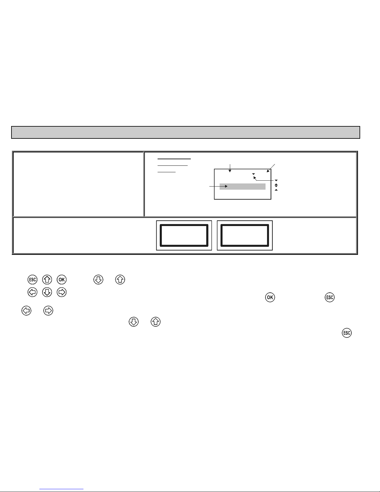
Programming can be done using the 6 buttons with the help of the 128x64 point graphic screen. There are three different kinds of images.
Measurement / operation images
(marked with capital letters in the upper right corner
(Appendix 5):
Measurement, see 5.10 Measurement mode
Bargraph image (output range)
User image, see 5.4 MultiCONT configuration
Relay assignment table
Current output assignment table
Error list, see 6. Error codes
Programming /
configuration
images:
Main menu
05
Current generators
Devices
Relays
Number of
menu table
Name
of the menu
Selected
menu
point
No further menu points
Further menu points down the line
Further menu points up and down the line
Further menu points up the line
Box messages / warnings indicate steps taken by the
unit or those to be performed
Scanning HART line
Device: 3
HART logical error
Click OK
See a summary of the programming below. A complete menu system is in Appendix 2. The relevant menu item and the value or character to be edited appears in a
highlighted form.
and are used to select options within the menu. The buttons are repetitive i.e. steadily pressing the button results in
continuous stepping (the menu repeats at the end).
Programming mode can be entered and a menu item can be selected by pressing
and exited by pressing .
The and buttons are used for editing parameters with numbers or text, selection of local values or for character positioning and for selection in some sub-
menus (e.g. Relay functions). Repeating function keys
and are used for scrolling numbers and characters when editing parameters with numbers or text.
(These two buttons are dual-functional - steady pressing results in continuous stepping up-down and in jumping to the beginning at the end). Use
to
acknowledge (quit) error messages (deletion of the error list).
Page 25
prw2101a0600p_01
25 / 105
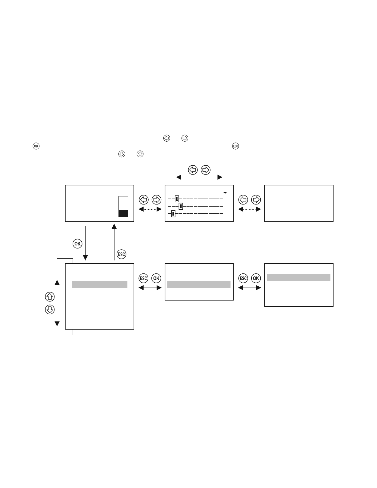
5.1.1. Scrolling and selecting menu items
The various display modes (M, B, U, R, C, E) can be selected using and buttons.
With button can enter into the Programming Mode or the selected menu point and can return with button.
The desired menu item can be selected using and (repetitive functioning i.e. steady pressing results continuous stepping and jumping to the beginning at the
end).
1: SE300-1 M
2: Errors: 2
3.125 m
Relays 18
02: R_IN_2
03: R_IN_3
01: R_IN_1
Main menu
05
Current outs
Devices
Relays
Error report
E
02: SE300-2: Sensor
01: SE300-1: Reply
123456789ABDCDEF R
R1
R2
R3
01: R_IN_1
19
Info
Programming
:
:
Default config
Restart
Short TAG
ID
Page 26
prw2101a0600p_01 26 / 105
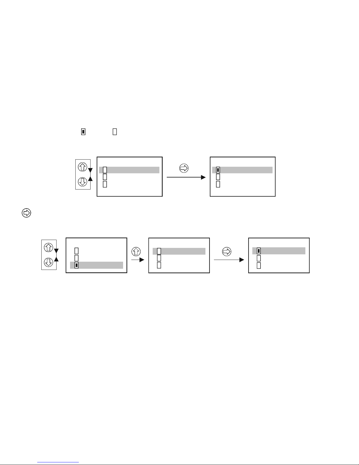
5.1.2. Activation (of devices, relays and current outputs) selection (of language, operation mode, etc.)
Devices on the list may be active ( ) or inactive ( ). Only active devices will be queried. Active relays and current outputs operate according to their configuration,
inactive relays are de-energized while inactive current outputs remain 0 mA.
Relays 18
02: R_IN_2
03: R_IN_3
01: R_IN_1
:
No active relay. R_IN_1 is active
Relays 18
02: R_IN_2
03: R_IN_3
01: R_IN_1
:
Use
to switch between active and inactive relay states.
Selection of the various modes (Relay mode, current output mode, language, etc.) is done similarly.
Language
43
German
French
Hungarian
Language
43
French
English
German
Language
43
French
English
German
After selection, the chosen language is immediately activated.
Page 27
prw2101a0600p_01
27 / 105
5.1.3. Assignment of outputs (relay and current) to the device
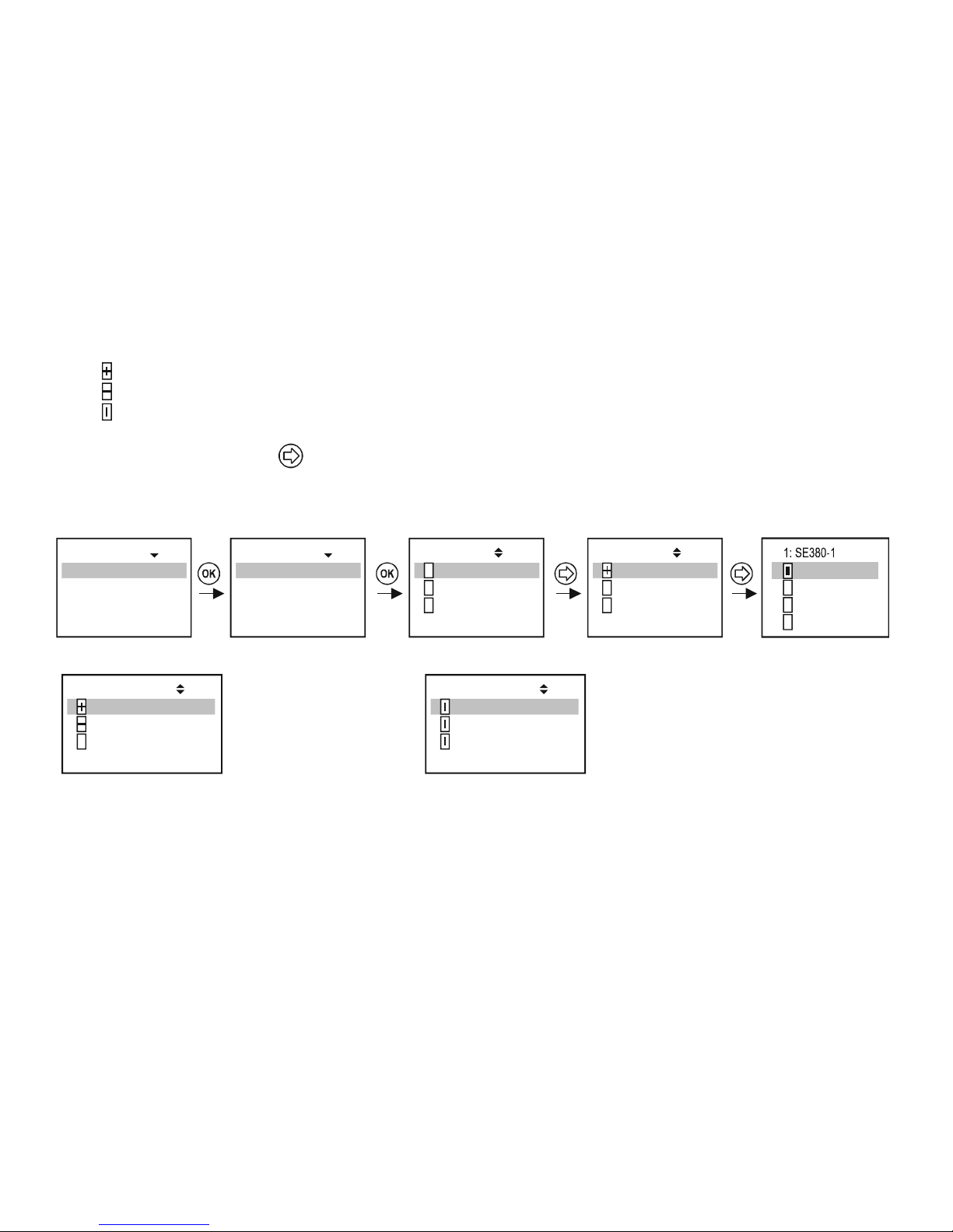
During configuration, the relays and current outputs should be assigned to the field devices and to their variables (PV, SV, TV, QV):
Value has a positive sign (for summation)
Value has a negative sign (for differential measurement)
Values from devices marked this way will be averaged
The above settings can be changed using
Assignment of device SE380-1 to the relay R_IN_1 in the MultiCONT should be performed as below:
1: SE380-1
2: SE380-2
3: SE360-1
:
Source 21
:
1: SE380-1
2: SE380-2
3: SE360-1
:
Source 21
:
Source
Function
Parameter
:
Programming 20
:
Program
Info
Short TAG
ID
01: R_IN_1 19
:
57
TV
PV
SV
QV
1: SE380-1
2: SE380-2
3: SE360-1
:
Source 21
:
Relay R_IN_1 is controlled by
the difference of the measured
values of SE380-1 and SE380-2
1: SE380-1
2: SE380-2
3: SE360-1
:
Source 21
:
Relay R_IN_1 is controlled by
the average of the measured
values of SE380-1, SE380-2
and SE360-1
Important: If there are more than one devices (sources) assigned to a relay (difference or average) then those devices should be programmed to
measure the same parameter (DIST, LEV, ...) in the same unit (m, ft, inch, ...)
Otherwise error message (Program) will appear. See 5.7, 5.8 and 6.
Page 28
prw2101a0600p_01 28 / 105
5.1.4. Entering parameter values
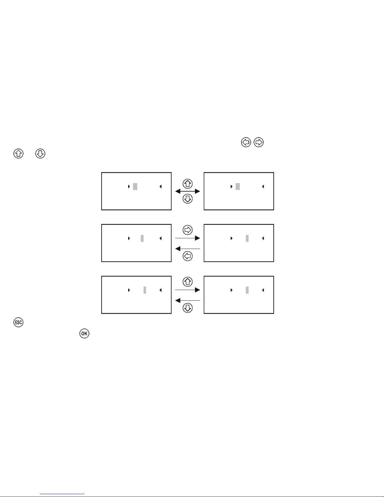
Parameters have signs and absolute values. Positioning the cursor to the sign and digits can be done using .
and are for modifying the value of either the sign or the digit.
Switching between the (+) and (-) signs
RP3 = 0
RP2 = 0.000
Parameter 23
RP1 = + 0000.000
RP3 = 0
RP2 = 0.000
Parameter 23
RP1 = – 0000.000
Changing cursor position
RP3 = 0
RP2 = 0.000
Parameter 23
RP1 = 0000.000
+
RP3 = 0
RP2 = 0.000
Parameter 23
RP1 = + 0000.000
Modifying the value of the digit (no carry-over)
RP3 = 0
RP2 = 0.000
Parameter 23
RP1 = 0010.000
+
RP3 = 0
RP2 = 0.000
Parameter 23
RP1 = + 0000.000
can be used to quit without saving.
To save the parameters, press
after RP3.
Page 29
prw2101a0600p_01
29 / 105
5.1.5. Editing character variables (e.g. Short TAG)
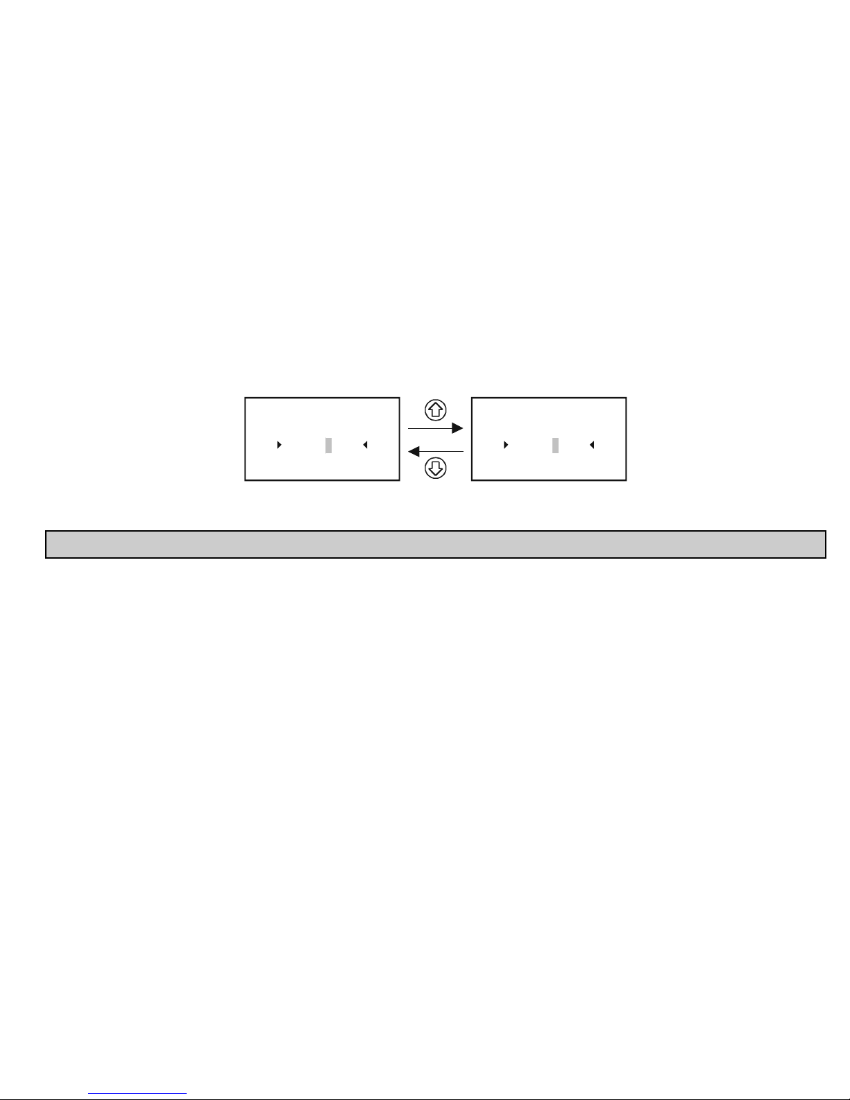
Scrolling order of the caracters:
ABCDEFGHIJKLMNOPQRSTUVWXYZ [ \ ] ^ _ ! ” # $ % & ’ ( ) * + , - . / 0123456789 : ; < = > ? @
The character being edited is displayed in INVERTED mode.
Short TAG 09
S T 3 0 0 - 1 2
Short TAG 09
S T 3 0 - 1 2
1
5.2. STEPS OF PUTTING INTO OPERATION A MultiCONT NETWORK
Steps of putting into operation:
Preparing transmitters and Universal Interface Modules. (see chapter 5.2.1) Transmitters should be given a unique „Short address”. If there are multiple
transmitters, then the address should not be zero!
Adding the devices in the loop into the device list. see chapter 5.2.3
Configuration of the state of the transmitters. Devices (transmitters) placed in the device list during the detection process automatically become active i.e.
the MultiCONT queries them constantly. This can be avoided by setting their state to be inactive (see chapter 5.2.3)
Detecting Universal Interface Modules: The detected modules (relays, current outputs) become inactive, meaning that MultiCONT does not control them.
Relay configuration: The relay should be assigned to one or more transmitters (sources), the mode of operation (function) should be specified, the
switching points should be configured (parameters RP1…RP3), and then it should finally be activated. See chapter 5.7.
Current output configuration: Similar to the relay configuration, see chapter 5.8.
Page 30
prw2101a0600p_01 30 / 105
5.2.1. Preparation of the Transmitters and the Universal Interface Modules.
5.2.1.1 Preparation of the Transmitters
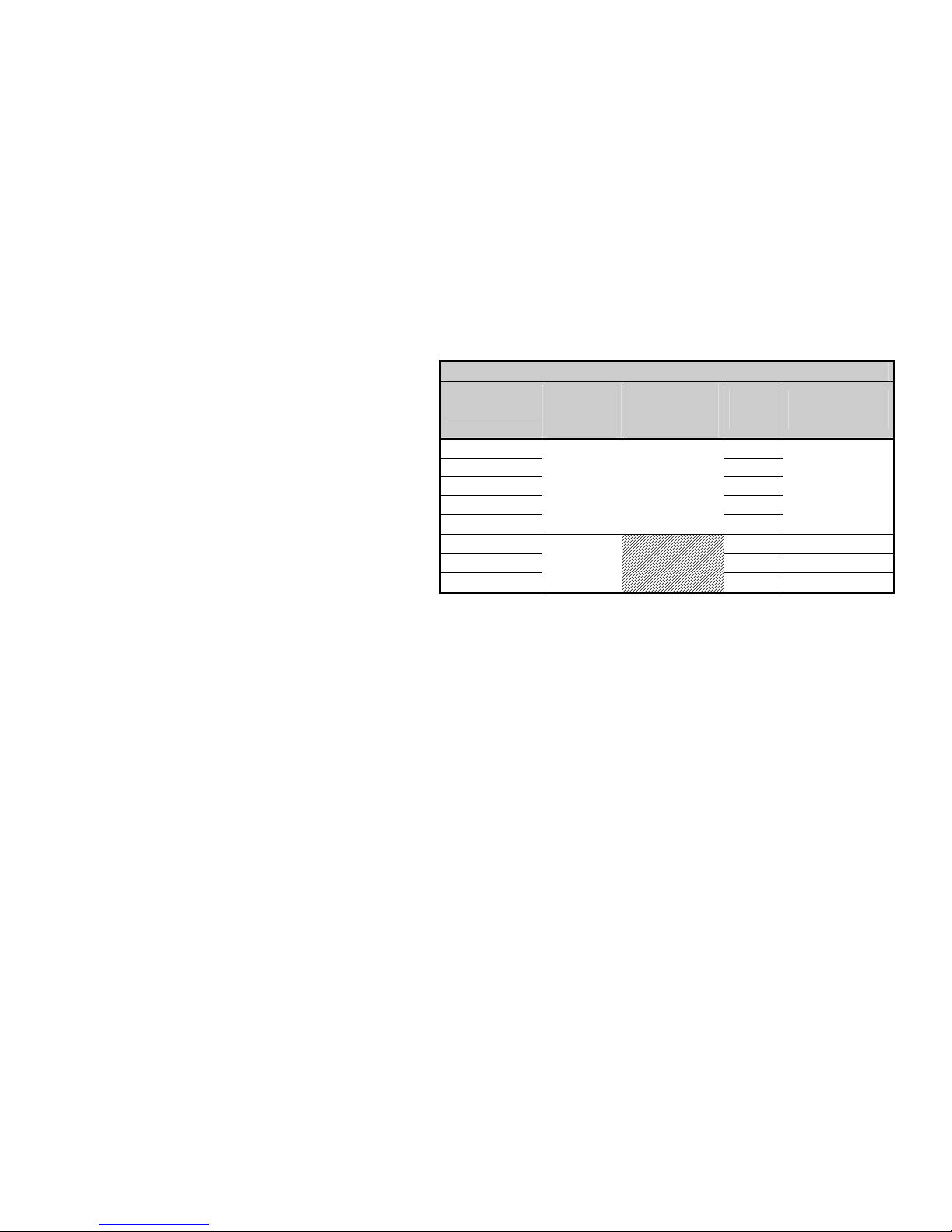
Data for NIVELCO made devices
DEVICE TYPE
„SHORT
ADDRESS”
PARAMETER
CONSTANT
CURRENT
PARAMETER
DEVICE
TYPE ID
DEFAULT „SHORT
TAG”
EchoTREK 4 wire 1
EchoTREK 2 wire 3, 4
EasyTREK 2
NIVOCAP 5
NIVOTRACK
P19 P08
6
XXXXXX
where xxxxxx
is the order or type
code of the
transmitter
e.g.: STA380
NIVOPRESS 21 DB500
UNICONT 22, 23 PDF400
THERMOCONT
P13
20 TB500
During this procedure, programming of the current outputs and “Short
address” (see Manual of the transmitters) of the transmitters should be
checked in laboratory circumstances. The loop current of the normal (nonEx) MultiCONT is max. 60 mA, and it is max. 22 mA for the Ex certified
version. If the loop current exceeds this value the voltage at the terminals
of the transmitters will be decreased to be too low for the transmitters to
start to operate. (There may happen that the transmitters could operate,
but HART signals will be distorted because the decreased terminal voltage
and communication may be failed or not be able to work.) In networks with
only one transmitter the short address of the unit can be 0, so the output of
the transmitter operates in 4-20mA range. In case of multiple transmitters
the short addresses should be set between 1…15 and then the current
output of the transmitters will be automatically limited to 4mA. The value of
this can be overrided by the fixed output current parameter (see Manual of
the transmitter). It is really important that loop current must not exceed the
given limit value. In addition to this, two or more instruments must not have
the same “Sort address” or “Long address” in order to provide error-free
operation.
Modification of the “Short address” can be performed with Eview
configuration software, or with the MultiCONT. In this case transmitters
should be connected and detected one by another and set the appropriate
“Short address”. The “Long address” of the device is given by the
manufacturer, which cannot be modified by the user.
Page 31

prw2101a0600p_01
31 / 105
5.2.1.2 Preparing of the Universal Interface Modules
The MultiCONT can be expanded by a maximum of
32 Universal Interface Modules. They can be
differentiated from each other using their „Short
Addresses”. Two or more modules with the same
address must not be in one system. Configuration
is possible using the row of DIP switches that can
be found on the top of the modules (0…31).
1
2
4
8
16
ON OFF
ADDR.
Example for setting the address:
4+8=12, this is the „Short Address” of the module.
5.2.2. Wiring
Wiring has to be done according to the previous instructions (See chapters 2.: Technical Data and 4.1: Arrangement of cable terminals)
Page 32

prw2101a0600p_01 32 / 105
5.2.3. Putting the MultiCONT into operation
Switching on initiates a 40 sec test process, during which MultiCONT tests the integrity of the memory where its settings are stored (See 5.9 The Boot Process).
If everything goes perfectly, then the following
No HART device
message appears on the screen, implying that the device table - the object
of the query - is empty yet.
To choose a programming Language (English, German, French, Hungarian) select the Language menu item under ”Main menu”/”MultiCONT
config”/”Language” using the and buttons and confirm it using the button.
From here on, the device will function using the selected language.
To detect devices in the loop select the ”Main menu”/”MultiCONT config”/” DEV detect” program.
It is essential not to confuse the Short address with the List-tag of the units. In order to make possible to search and identify HART-capable devices, it is necessary
to assign Short addresses ranging from 1 …. 15 to the devices during their (laboratory) programming. MultiCONT however registers the devices on the basis of the
List-tags ranging from 1, … 8, 9, A, B, … F.
At this stage configure the settings specific to the functioning of the system (display, backlight, etc.) under “Main menu” / “MultiCONT config”. See chapter 5.4.
Relays (see chapter 5.7) and current outputs (see chapter 5.8) should be programmed in accordance with the requirements of the application.
Settings can be protected via “Main menu”/“MultiCONT config”/”Password” with a secret code (software protection) and by using the program protection switch
K1 (hardware protection) on the back of the front panel (see chapter 7).
Page 33
prw2101a0600p_01
33 / 105
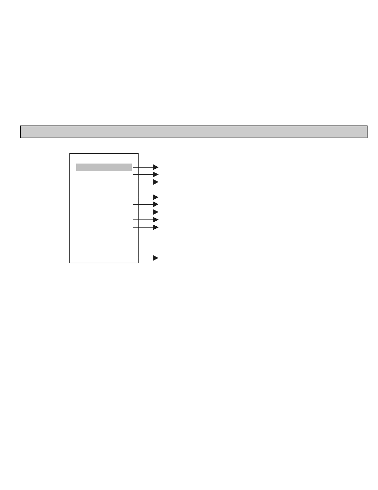
5.3. MAIN MENU
The Main menu can always be accessed from measurement mode by pressing OK.
MultiCONT conf.
Save config.
Load config.
Default config
Restart
Devices
Relays
Current outs
Inputs
UIM-s
Main menu
01
Setting features of devices (see chapter 5.5)
Programming relay mode of operation and parameters (see chapter 5.7)
Programming current generator mode of operation and parameters (see chapter 5.8)
Information about UIM-s, TAG modification
Programming of parameters affecting operation (see chapter 5.4)
Saves the actual configuration
Loads the saved configuration
Reset to default. Clears device list, relay and current output
assignments and resets the parameters of "MultiCONT conf."
Does not clear the switching number and work time.
The steps in 5.2.3 have to be repeated (Putting the MultiCONT into operation).
Simulate repowering ( RESET )
(see chapter 5.11)
parameters,
Page 34
prw2101a0600p_01 34 / 105
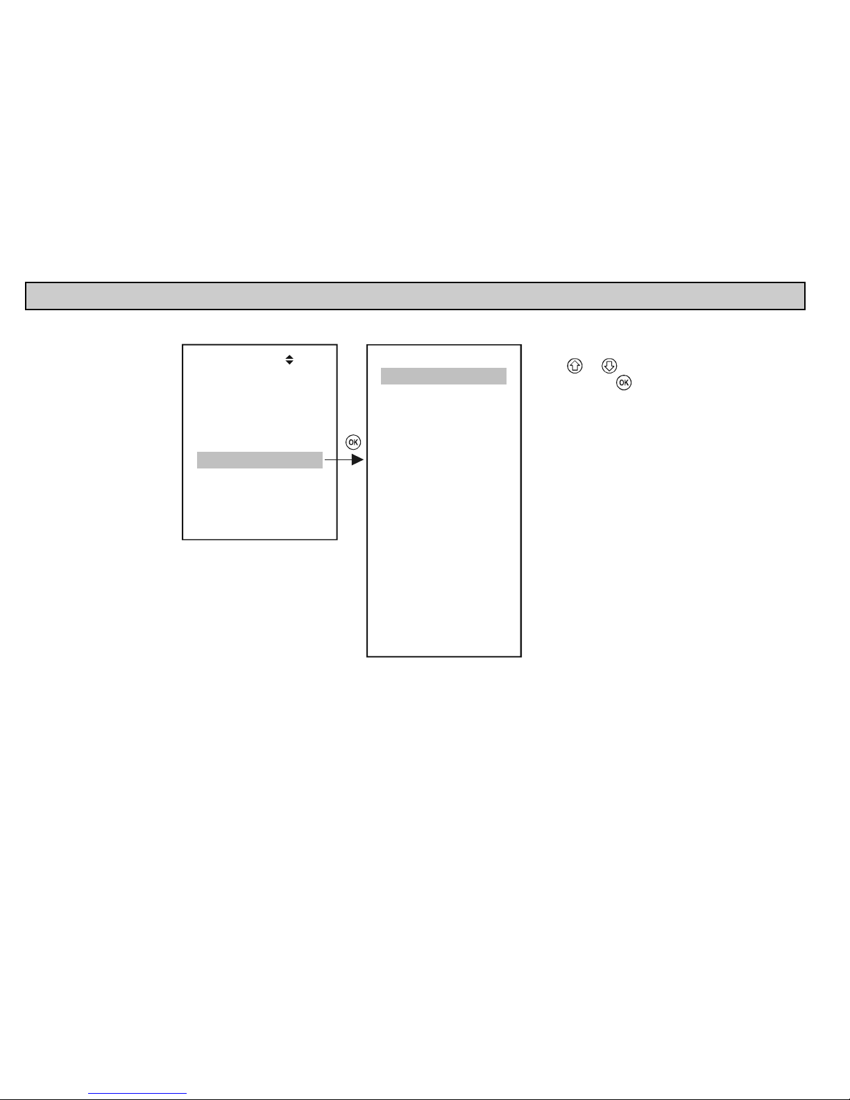
5.4. MULTICONT CONFIGURATION
The selected menu item appears in inverted mode on the display, and is marked in grey in this manual.
Devices
Current outs
Inputs
UIM-s
Default config.
Restart
Relays
MultiCONT config
Save config.
Load config.
Main menu
01
DEV detect
Main display
List display
User display
Language
Backlight
Display contrast
Report
Prog CS
EXT detect
Sorting
Trend
HART
USER RS485
LOG
Password
Clock
MultiCONT conf.
35
Select menu items
using and buttons
Enter by pressing
Page 35
prw2101a0600p_01
35 / 105
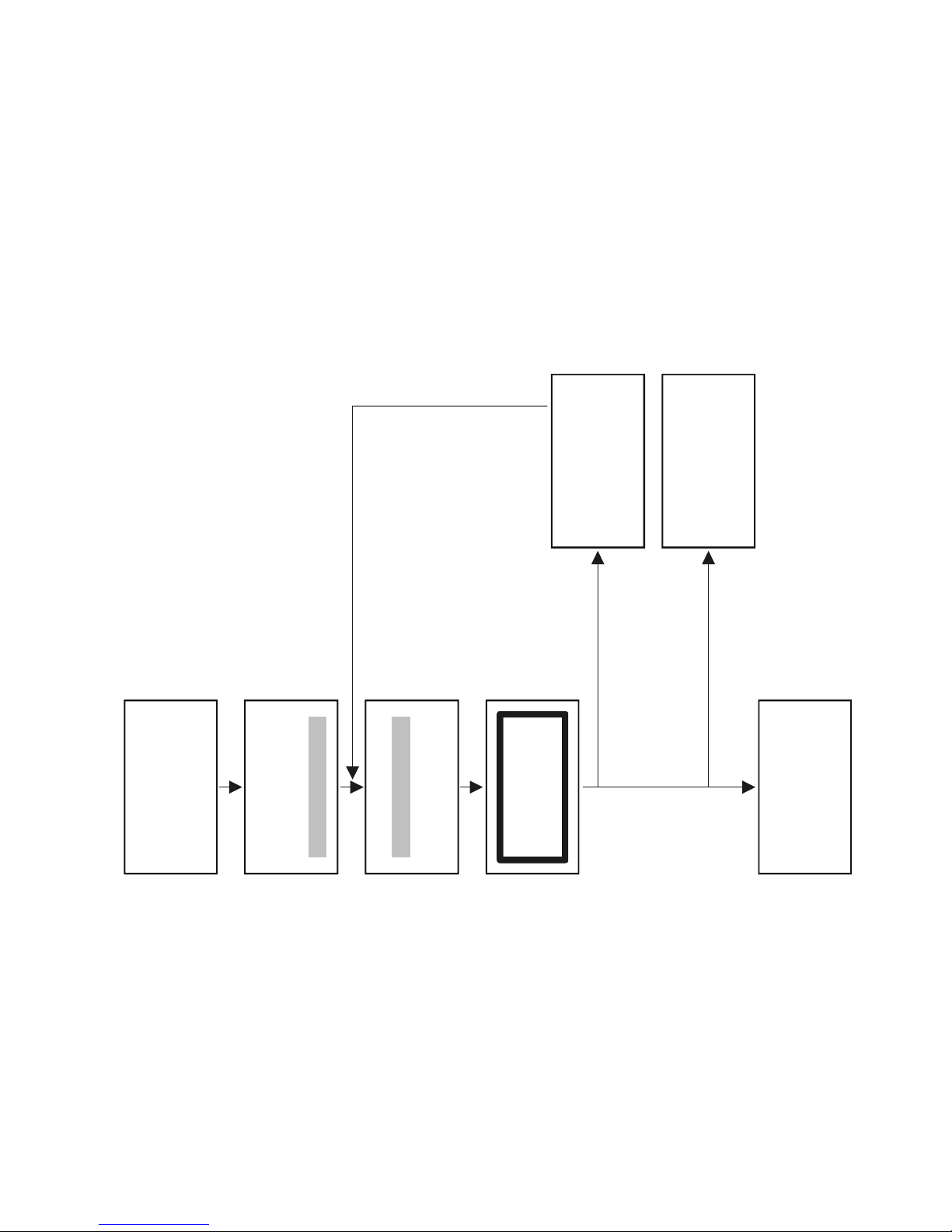
5.4.1. DEV detect:
Queries the transmitters via HART line from 0 to 15, and lists them with 1…9, A, B, C, D, E, F tag.
Main menu
01
MultiCONT config
Inputs
UIM-s
MultiCONT conf.
35
DEV detect
EXT detdct
M
No HART device
Scanning HART line
Device: N
Same address
M
No HART device
Deetect DEV
37
2: SEA-360 (07)
- - - -
>
SAVE
<
- - - -
1: SPA-440 (01)
Message appears
and detection starts
N=0...15
MultiCONT found devices with the
same long address. This is an error state
and detection stops.
Return to
by clicking OK
MultiCONT config
(see next page)
No device found
(device list
will remain empty,
)see next page
List of detected devices (Short TAG)
Short address in brackets
"OK"
"OK"
"OK"
"OK"
Page 36

prw2101a0600p_01 36 / 105
MultiCONT detects devices in accordance to the Short address (that is why two or more devices must not have the same Short address)
After detection however, query will be performed using the Long address that consists of the following three parts:
Manufacturer’s ID: (See APPENDIX 1. At the end of the Manual (for NIVELCO products it is:151)
Device type ID: identification number of the device type (see chapter 5.2.1.1)
Device ID: number generated during production (0…16777215)
When detection stops with the „Same Long address” error message there are two ways to identify the devices with the same Long address
Devices should be removed one by one until DEV detect program can run to completion.
Obviously the address of one of those devices remained in the loop is the same as the address of the unit last removed.
Then reconnecting the devices one by one again, after detection, the Factory ID, Device Type ID, and Device ID can be read in from the “Main
menu”/”Devices” menu item (see chapter 5.5 programming devices)
The Long addresses of the transmitters can be read using the Eview configuration software (preset to work with Short Addresses) provided with HART capable
devices
Since the Long address can not be modified please send such a unit back to the manufacturer, or call our Export Sales Department for help.
Question: what happens if the MultiCONT does not find all the devices?
1. One of the transmitters is not HART-capable. Check the transmitter type on the name plate.
2. Faulty device. Dismount the unit and check it in laboratory circumstances.
3. Faulty wiring connection.
4. The terminal voltage of the unit is small, check the configuration of the current outputs of the transmitters (See chapter 5.2.1.1 preparation of transmitters)
5. None of the devices are responding, please check:
Is there any voltage between terminals L+ and SH? If no, then the output is faulty, or there is a short-circuit on the line.
If there is voltage between terminals L+ and SH, then check if the terminals L+ and L- are short-circuited or if there is an open-circuit.
Then, the next steps will be adding the device to the list, and setting the device.
Page 37
prw2101a0600p_01
37 / 105
Searching result may be the following:
No HART device
Press OK
No device was found in the loop
DEV detect
37
- - - - > SAVE < - - - -
2: SEA-360 (- -)
3: SEA-360 (07)
4: SPA-380 (08)
1: ST-300 (01)
Device is found in the loop:
The devices above the ---SAVE--- line are the ones already included in the list. This list is empty if the unit is either
newly manufactured or if reset („Main menu”/”Default”). The units under this line are not in the list, but have
responded to a query. The „Short Address” (Polling Address) appears in brackets. Whereby a unit in the list responds,
the „Short Address” will appear in brackets, otherwise a (--) will appear instead.
Upon selecting any unit that has responded (either above or below the line) an pressing „OK”, the „Short Tag” can be changed.
MultiCONT only handles units above the line.
Note:
If the number of the devices in the loop is known and MultiCONT detected them already, detection process can be interrupted by pressing the button
(the button should be pressed until „DEV detection end” message appears).
Page 38
prw2101a0600p_01 38 / 105
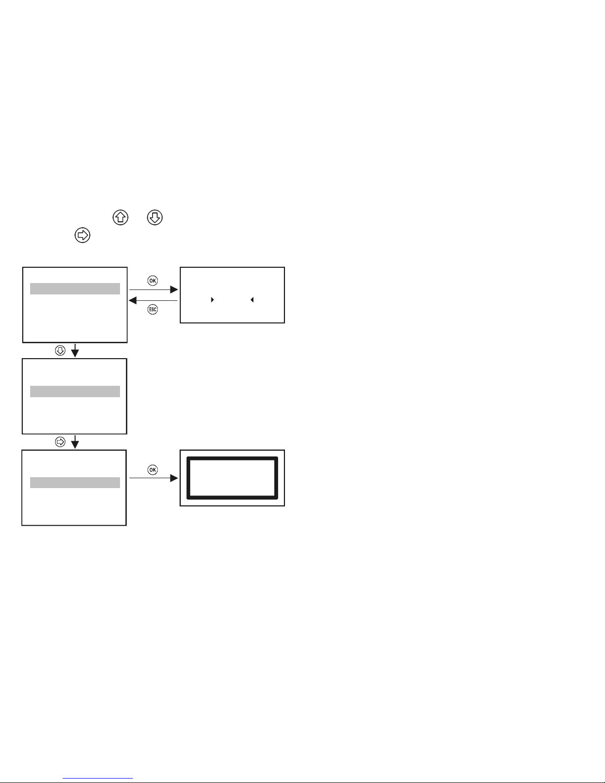
Reorganising the list can be done in the following manner:
Select the unit using
and buttons
Press the
button to move the unit to the end of the list at the other side of the line
Selecting the SAVE line saves the list above the SAVE line.
„Short TAG” can be modified
Note:
When pressing button does not move the selected device above
the --- SAVE --- line it means that the list above the --- SAVE --- line is full
and you cannot add more devices. The lenght of the list depends on the
type of the MultiCONT (1, 2, 4, 8, 15, see order code)
DEV detect
37
- - - - > SAVE < - - - -
2: SEA-360 (- -)
3: SEA-360 (07)
4: SPA-380 (08)
1: ST-300 (01)
DEV detect
37
- - - - > SAVE < - - - -
2: SEA-360 (- -)
3: SEA-360 (07)
4: SPA-380 (08)
1: ST-300 (01)
DEV detect
37
- - - - > SAVE < - - - 2: SEA-360 (07)
3: SPA-380 (08)
4: SEA-360 (- -)
1: ST-300 (01)
2: SEA-360
38
ST300
List saved
Press OK
Saving the list above the ----> SAVE <---- line
The units in the saved list automatically become active!!
Page 39
prw2101a0600p_01
39 / 105
1: ST300 M 1 LEV
2006.04.04
2.452 m
A 11:46
2: SE300 M 2 VOL
2006.04.04
41.18 m
3
A 11:46
Once back in measurment mode the measured values of the
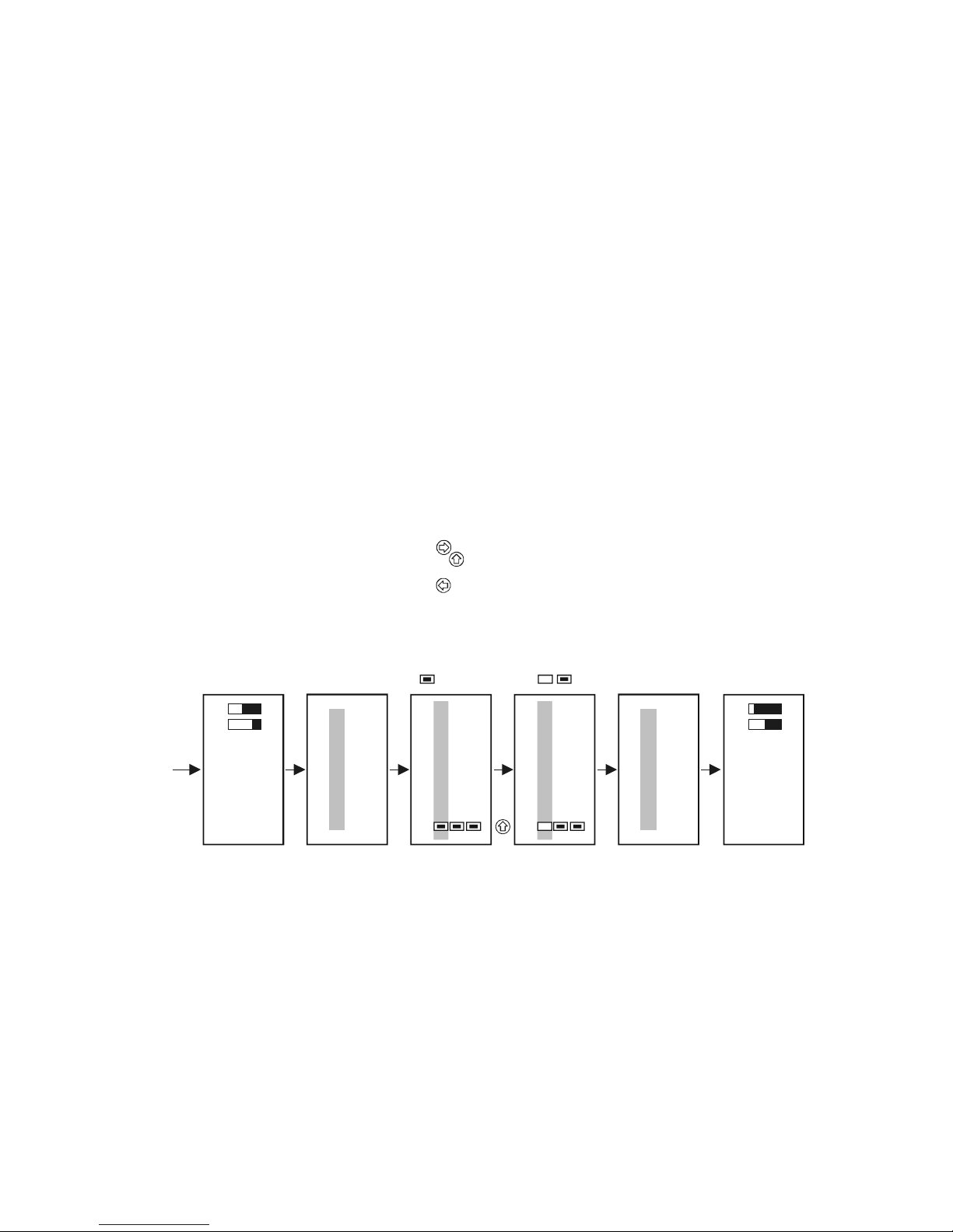
devices found during detection are displayed one after another on the display.
For the meanings of the captions on the display see 5.10 (Measurement mode)
If the measured data of a given device are not needed temporarily, no need to delete it
from the list, it is enough to inactivate it in the following manner.
Main menu
01
Current outs
Devices
Relays
Main menu
05
Current outs
Devices
Relays
Devices
06
02: SE300
03: ST–HCL
01: ST300
Devices
06
02: SE300
03: ST–HCL
01: ST300
"OK"
"OK"
"ESC"
"ESC"
Upon re-entering measuring mode the measured values of
the inactive d evice are not shown on the display and
states of assigned relays and current outputs do not change.
Device is active
Select the device with and
and deactivate it by pressing
Inactive device
ctive device A
Page 40
prw2101a0600p_01 40 / 105
5.4.2. EXT detect:
For detection of, external expansion (Relays, Current Output, or Combined) modules if available.
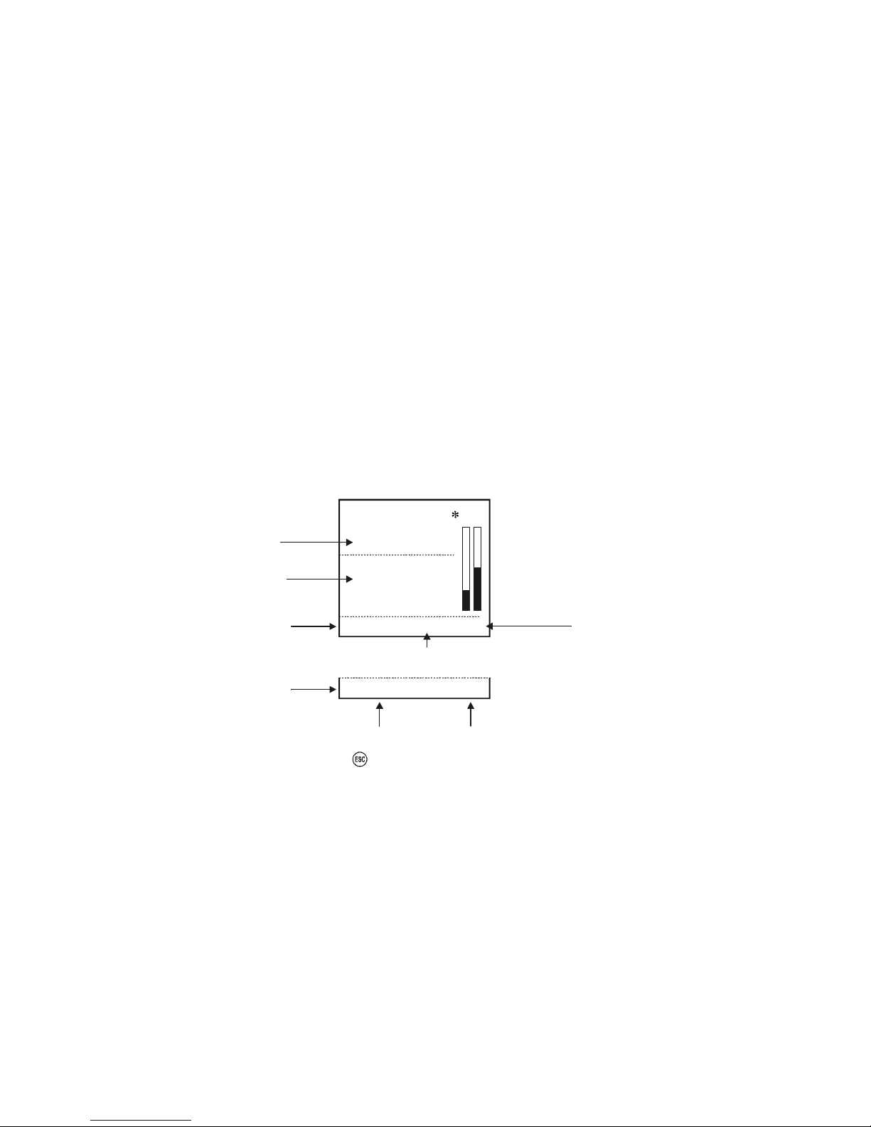
The query process is similar to that of the DEV detect mode, the only difference being that the modules that get into the list remain in an inactive state.
(See 5.2.3 Putting the MultiCONT into operation)
The detected relays or current outputs (4-20 mA) will placed at end of the Detected EXT list.
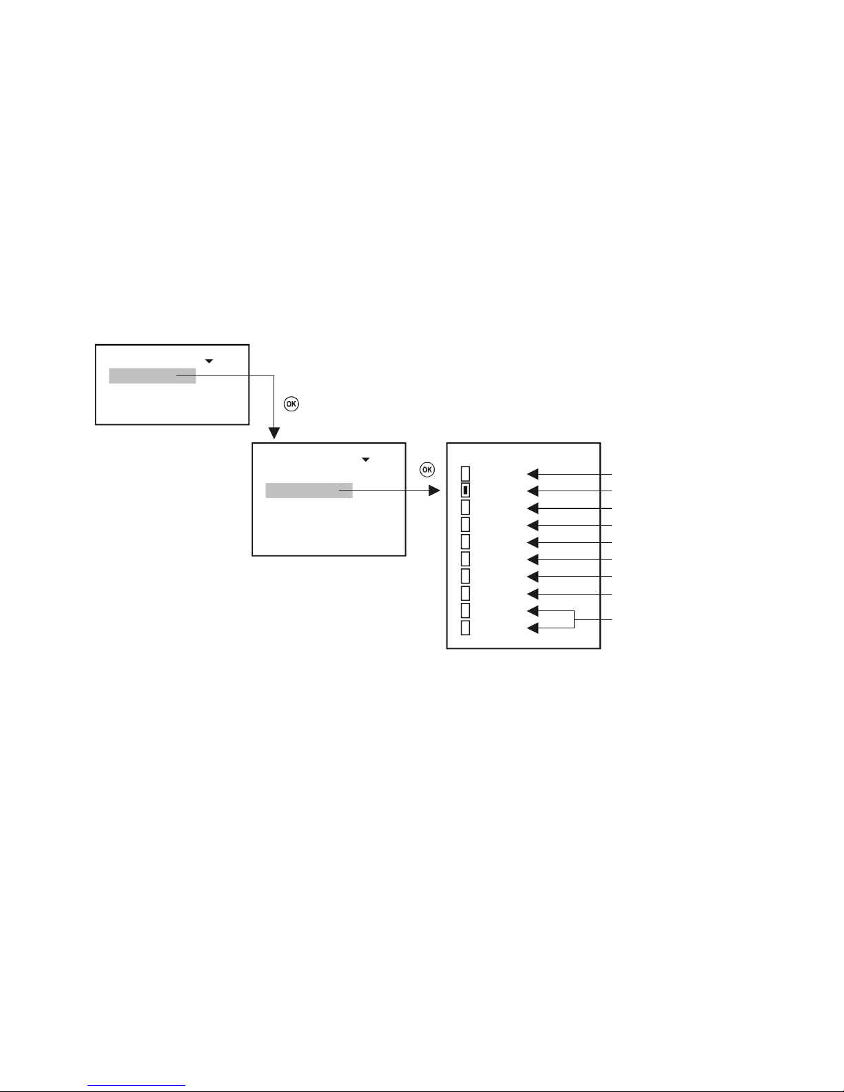
5.4.3. Main Display:
The main display consists of 3 parts: „Main display”, „List display” and „Status field” See 5.10 .
Among these, the „Main display” and „List display” can be freely selected for each device.
The quantity to be displayed and the rounding of the decimal part can be set in the „Main display”.
This is where to configure the stepping of the results of the transmitters on the display.
n: S 300E-11
M
FLOW
A 06:412006.04.11
5486. m
Code of the device error
or "Locked" message if
program protecting switch is on
No. of error logs
Acknowledge, (delete)
with
SV: 0.852 m
LEV: 0,514 m
TOT1: 1542 m3
TOT2: 1.25 E7 m3
Main display
List display
Status
field
Err11Errors: 4
PV
l/s
(no errors)
(max 4 rows)
A
= absolute time
R = relative time
2
Status
field
(on error)
A
ctual date& time
Page 41
prw2101a0600p_01
41 / 105
5.4.3.1 Source
The quantity to be displayed in the “Main display” can be selected independently for each transmitter. Cross-check your selection in “Main menu”/”MultiCONT
config.”/”HART”/”CommandSet”, to confirm the selection of the appropriate command containing the desired quantity.
2: SE360
42
PV
SV
TV
QV
Current
Percent
Level
Level%
TOT1
TOT2
Primary Value
Secondary Value
Tertiary Value
Quaternary Value
Current out of the transmitter*
PV in %
Level
Level in %
TOT1 and TOT2 Totalizer Values
during flow measurement
1: SE380
2: SE360
3P8
:
x: ST340
: S 3 0
Source 56
:
Source
Rounding
Step
Main display 55
:
* Output current, as a displayed quantity is recommended to use only if there is only one device in the system, and if the „Short Address” is zero,
i.e. the current output is not constant.
Page 42
prw2101a0600p_01 42 / 105
5.4.3.2 Rounding
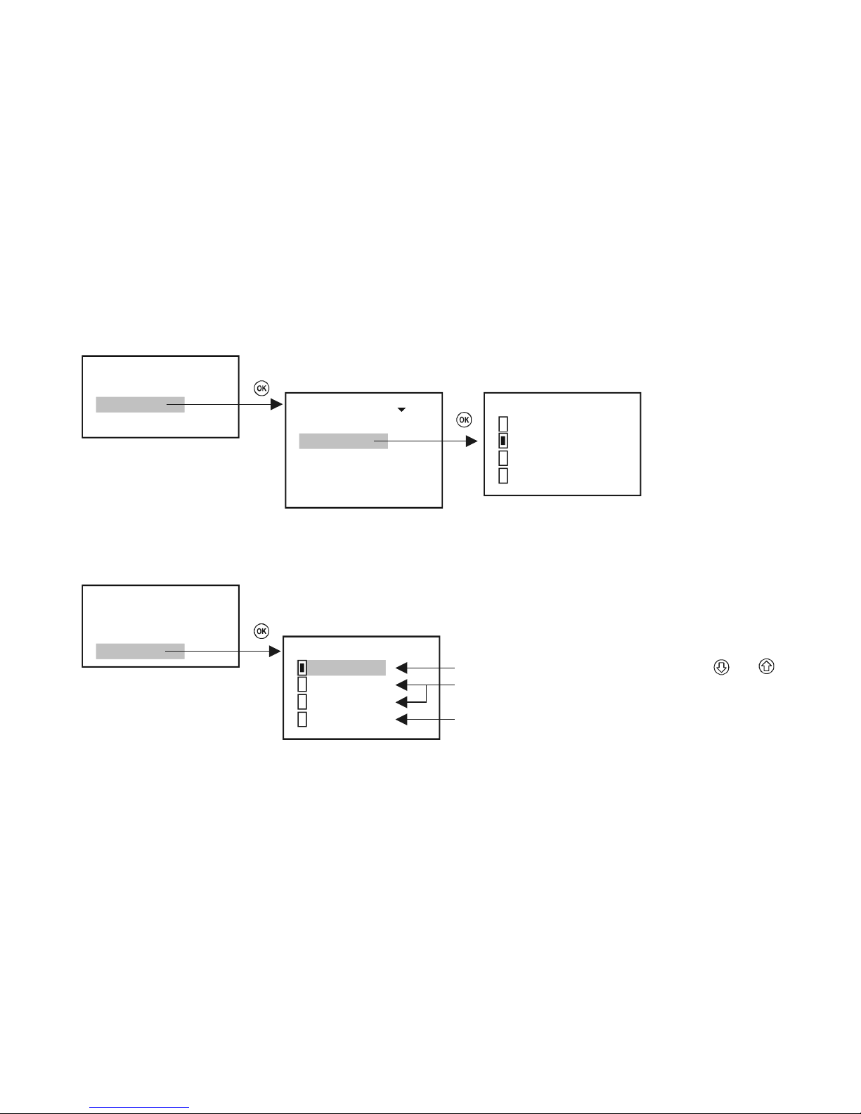
The MultiCONT by default rounds to 4 decimal digits i.e., the quantity is displayed with precision of 4 decimals.
The rounding is for the main image quantity only.
SE360 59
No
x.xxx
x.xx
x.x
1: SE380
2: SE360
3P8
:
x: ST340
: S 3 0
Rounding 70
:
Source
Rounding
Step
Main display 55
:
5.4.3.3 Stepping
Stepping is related to the display only. The query of the transmitters and the control of the relays and current outputs operates constantly, depending on the cycle
time set in the background ( „Main menu”/”MultiCONT config.”/”HART”/”Cycle time”).
Source
Rounding
Step
Main display 55
:
Step 48
Manual
Auto step 5s
Auto step 10s
Polled
:
manual stepping of the devices on the display using and
automatic stepping at 2 different speeds
refreshes the display after quering the device
Page 43
prw2101a0600p_01
43 / 105
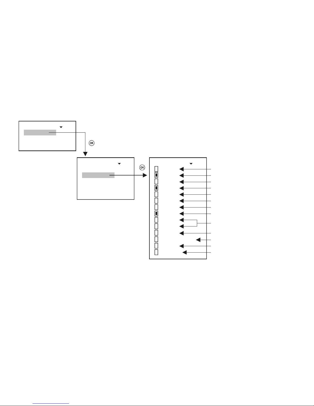
5.4.4. List display
Max. 4 quantities can be selected.
2: SE360 62
PV
SV
TV
QV
Current
Percent
Level
Level%
TOT1
TOT2
Status
PV rate of change
Working
Head of fl.
Primary Value
Secondary Value
Tertiary Value
Quaternary Value
Current out of the transmitter*
PV in %
Level
Level in %
TOT1 and TOT2 Totalizer Values
during flow measurement
Status of the instrument
Change speed rate of Primary Value
Working hours of the instrument
Level (h) for calculate instantaneous
flow in case of flowmetering
180
2E6
3P8
:
x: ST340
: SE3
: S 3 0
: S 3 0
Source 61
Source
List display 60
:
* The output current, as a display quantity is recommended to use only, if there is only one device in the system, and if the „Short Address” is zero, i.e., if the current
output is not constant.
** The MultiCONT calculates the value of PV rate of change in every 5 sec. If there are more transmitters in the loop and this cycle time is more than 5 sec,
calculation of PV_Rate ( t1 - t2 5 sec) is performed per cycles.
Change speed rate of PV [PV/min]=( PV
t1-PV t2 )×60/(t1-t2)
Page 44
prw2101a0600p_01 44 / 105
5.4.5. User Display:
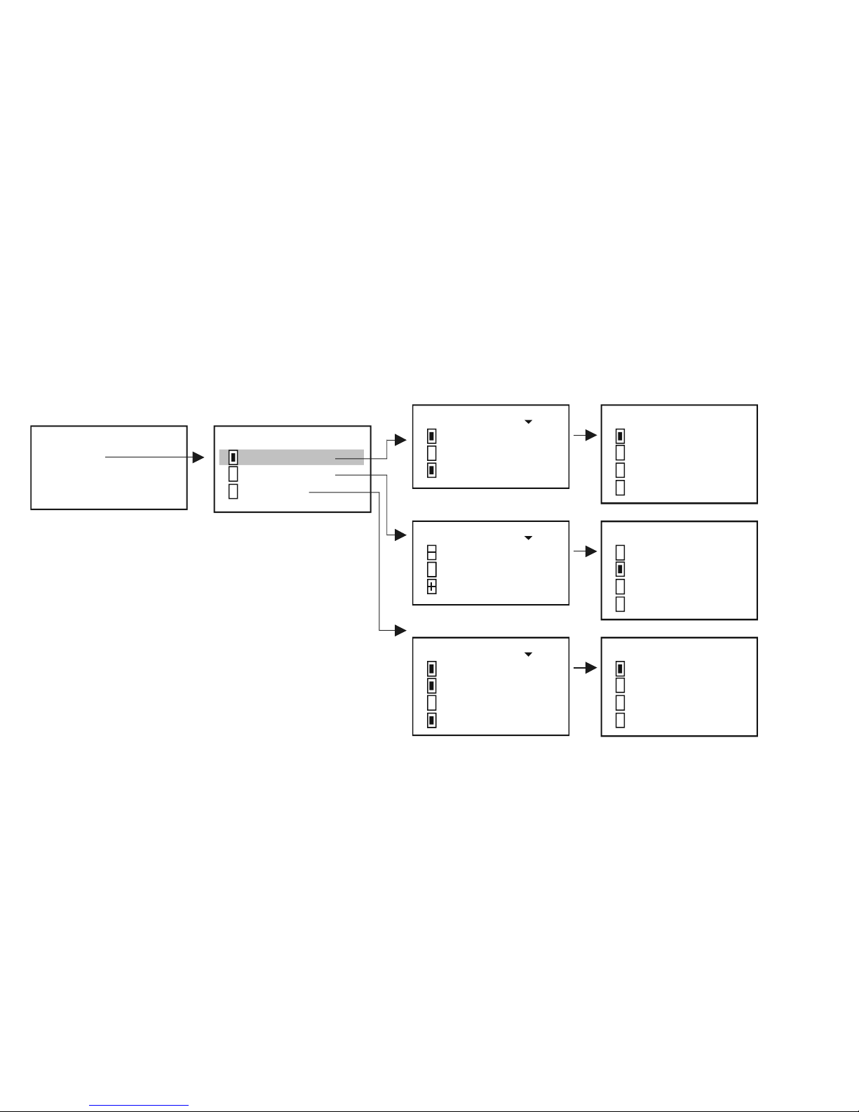
In measuring mode (See chapter 5.10) the user can select a display format besides the display showing the measured data and this can be seen in the user display.
We will receive an error message in the use’s image if:
Only one device is selected to display double, difference or average.
In the case of difference or average display for given transmitters, the values or dimensions are different.
5.4.5.1 Editing the user display
Type 6 51
Multiple
Difference
Average
1 PA-380
2EA-8
3PA-6
: S
: S 3 0
: S 3 0
Difference 52
:
1 PA-380
2EA-8
3PA-6
: S
: S 3 0
: S 3 0
Multiple 52
:
1 PA-380
2EA-8
3PA-6
4: SPA-380
: S
: S 3 0
: S 3 0
Average 52
:
SPA-380 65
PV
SV
TV
QV
SPA-380 65
PV
SV
TV
QV
SPA-380 65
PV
SV
TV
QV
Type
User display 63
:
Result of this setting
is shown on the following page.
Page 45
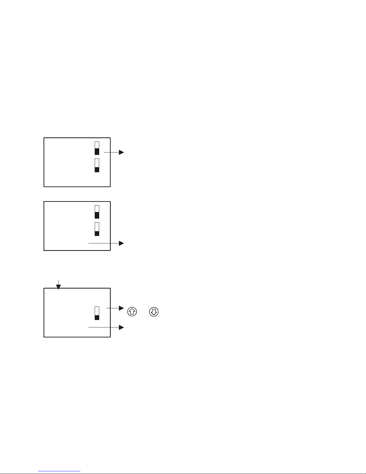
prw2101a0600p_01
45 / 105
5.4.5.2 The resulted user displays
Multiple
1: SPA-380 LEV
SV=
3: SPA-360 VOL
12.45 m
SV=
125.3 m3
U
Bargraph / Output range
Difference
1: SPA-360 LEV
+PV=
3: SPA-380 LEV
-PV
12.45 m
=
15.32 m
–2.87 m
U
difference of SPA-360 and SPA-380
Average
A 134
3 P 380 LEV
PV
:
: S A-
=
3.19 m
15.32 m
U
the calculated average
List number of devices whose avera
g
e value is
calculated by MultiCONT
The average value calculated from the measurement
result of the selected devices can be stepped using
and
Page 46
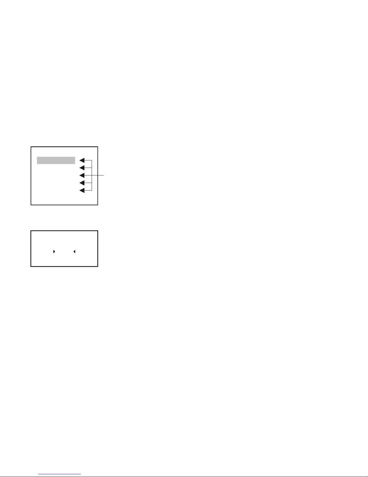
prw2101a0600p_01 46 / 105
5.4.6. HART
In this menu, it is possible to configure MultiCONT properties, the settings related to the transmitter query and also to choose the HART commands which the
MultiCONT uses to communicate with the devices.
HART 68
Short TAG
Polling address
Message
Description
Date
Command set
MultiCONT properties
5.4.6.1 MultiCONT Short TAG
Arbitrary 8-character identifier
Short TAG
54
P-100
Page 47
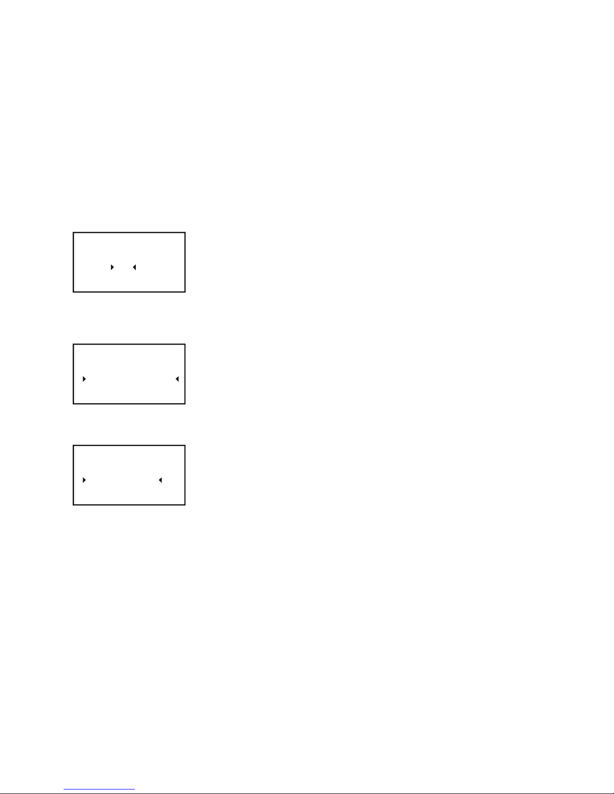
prw2101a0600p_01
47 / 105
5.4.6.2 Polling Address
If multiple MultiCONT-s are to be connected to a single system via RS485, then this address differentiates them.
Polling address
54
00
5.4.6.3 Message
An arbitrary message (usually related to the operation, and max 32 characters) can be assigned to a device.
To change rows use „OK” and „ESC”.
Message
54
MULTICONT PROCESS
CONTROLLER
5.4.6.4 Description
An arbitrary text that can be assigned to a device ( max 16 characters )
Description
54
MULTICONT P-100
Page 48
prw2101a0600p_01 48 / 105
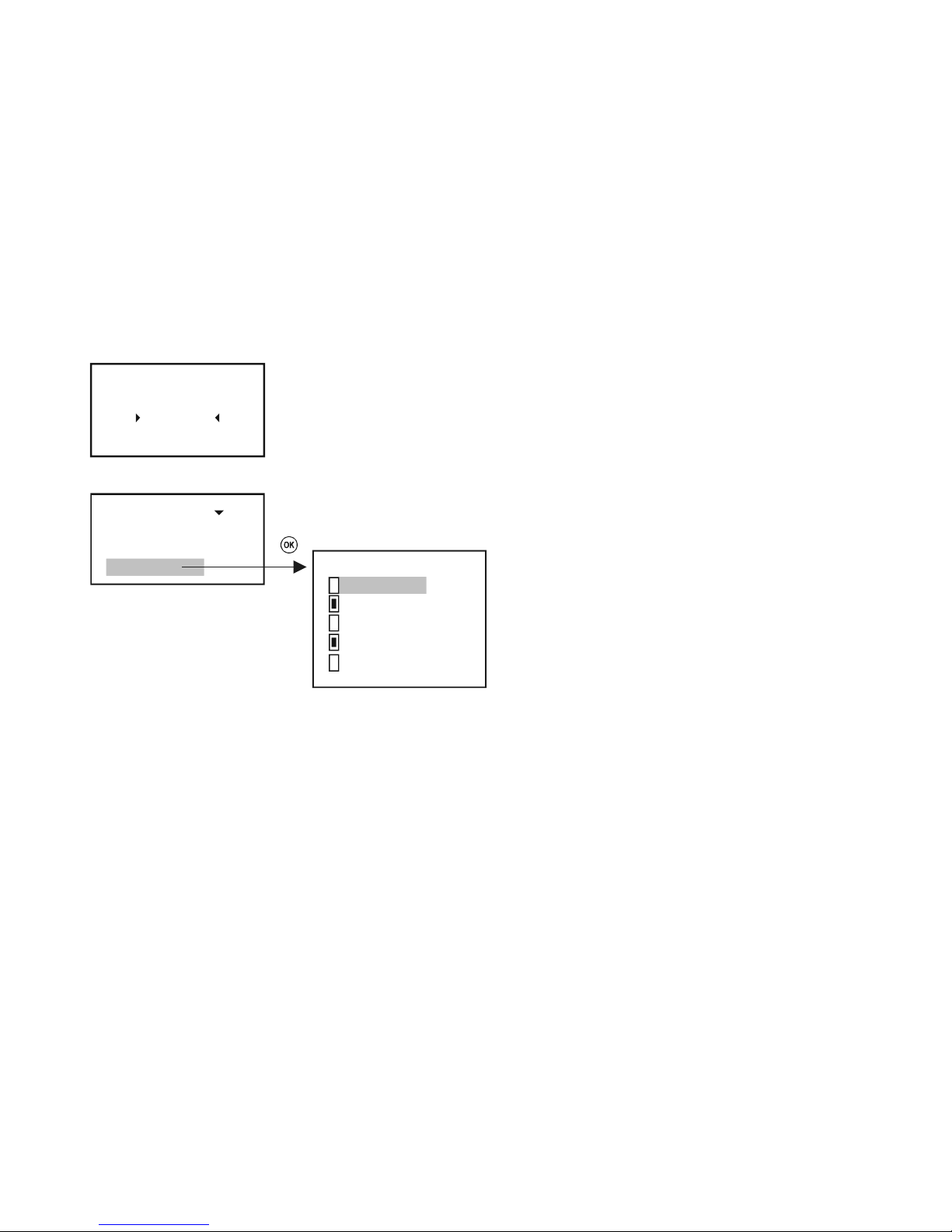
5.4.6.5 Date
The date assigned to the MultiCONT
Date
54
1900.00.00.
5.4.6.6 Command Set
1: SE360
2: ST380
3: SE380
Command set 66
:
3: SE380 67
COM1
COM2
COM3
NIV128
NIV129
:
The communication between the MultiCONT and the devices is via different commands. The MultiCONT sends a command containing the address of the device,
which responds in accordance with the standards. Some of the commands are universal, while others are device-specific. The appropriate commands are selected
automatically based on the data required to control the display, relays, and current outputs. This can be checked or modified in this menu point. If a command
became unselected which is needed for appropriate operation, „Program failure” message will be generated in the relays and current outputs. The display flashes,
showing that the result will not be refreshed, because the needed HART command for this operation is unactivated. So the modification of this option is not
recommended or it needs great care! If multiple commands are selected, then the refresh time increases (display, relay, and output current modification).
MultiCONT uses the following commands to communicate with the devices.
COM1: query of primary quantities/values
COM2: the output current in mA and in % (output range)
COM3: the primary, secondary, tertiary and quaternary values
Page 49
prw2101a0600p_01
49 / 105
These commands can be interpreted by any device belonging to any manufacturer.
The commands below can only be interpreted by NIVELCO products:
NIV128: device specific command optimalized for DIST, LEV, VOL measurements
NIV129: device specific command optimalized for DIST, LEV, FLOW, TOT1, TOT2 measurements
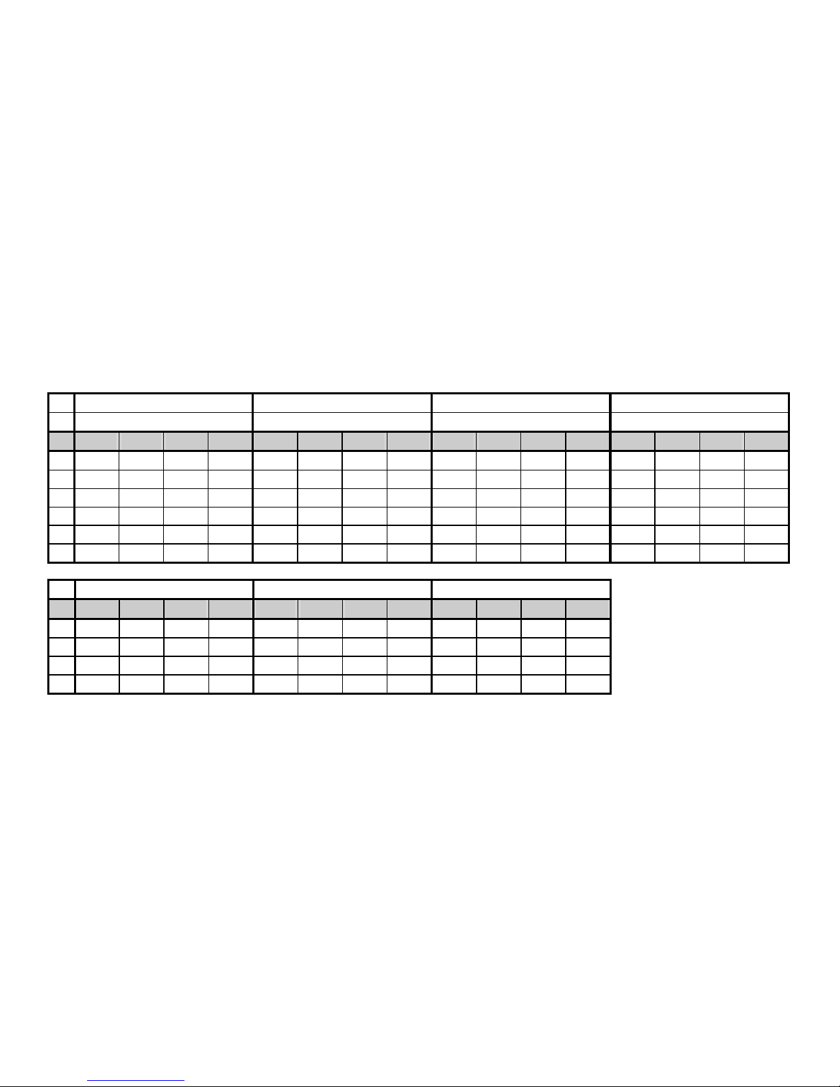
The table below shows the contents of the responses of NIVELCO-manufactured devices to given commands:
COM3: 03 Universal HART command
EchoTREK 4-wire. EchoTREK 2-wire. NIVOTRACK NIVOCAP
EasyTREK EasyTREK
P01 PV SV TV QV PV SV TV QV PV SV TV QV PV SV TV QV
0 DIST LEV DIST Temp DIST Temp - - DIST Temp - - % - - -
1 LEV LEV DIST Temp LEV DIST Temp - LEV DIST Temp - LEV % - -
2 LE% LEV DIST Temp LE% LEV DIST Temp LE% LEV DIST Temp LE% LEV % -
3 VOL LEV DIST Temp VOL LEV DIST Temp VOL LEV DIST Temp VOL LEV % -
4 VO% LEV DIST Temp VO% LEV DIST Temp VO% LEV DIST Temp VO% LEV % -
5 FLO LEV DIST Temp FLO LEV DIST Temp - - - - - - - -
NIVOPRESS UNICONT THERMOCONT
P10 PV SV TV QV PV SV TV QV PV SV TV QV
0 P* - - - Prog** Iin - - Temp - - 1 P* - - - Prog** Iin - - Temp - - 2 LEV P* - - Prog** Iin - - - - - 3 LEV P* - - Prog** Iin - - - - - -
* P: pressure
** Prog: the value calculated by the device from the input current ( I
in
).
During configuration, it is necessary to set the value ( e.g. 4 mA = 0 m
3
, 20mA = 125 m3 ) corresponding to the incoming 4…20mA ( Iin )
Page 50
prw2101a0600p_01 50 / 105
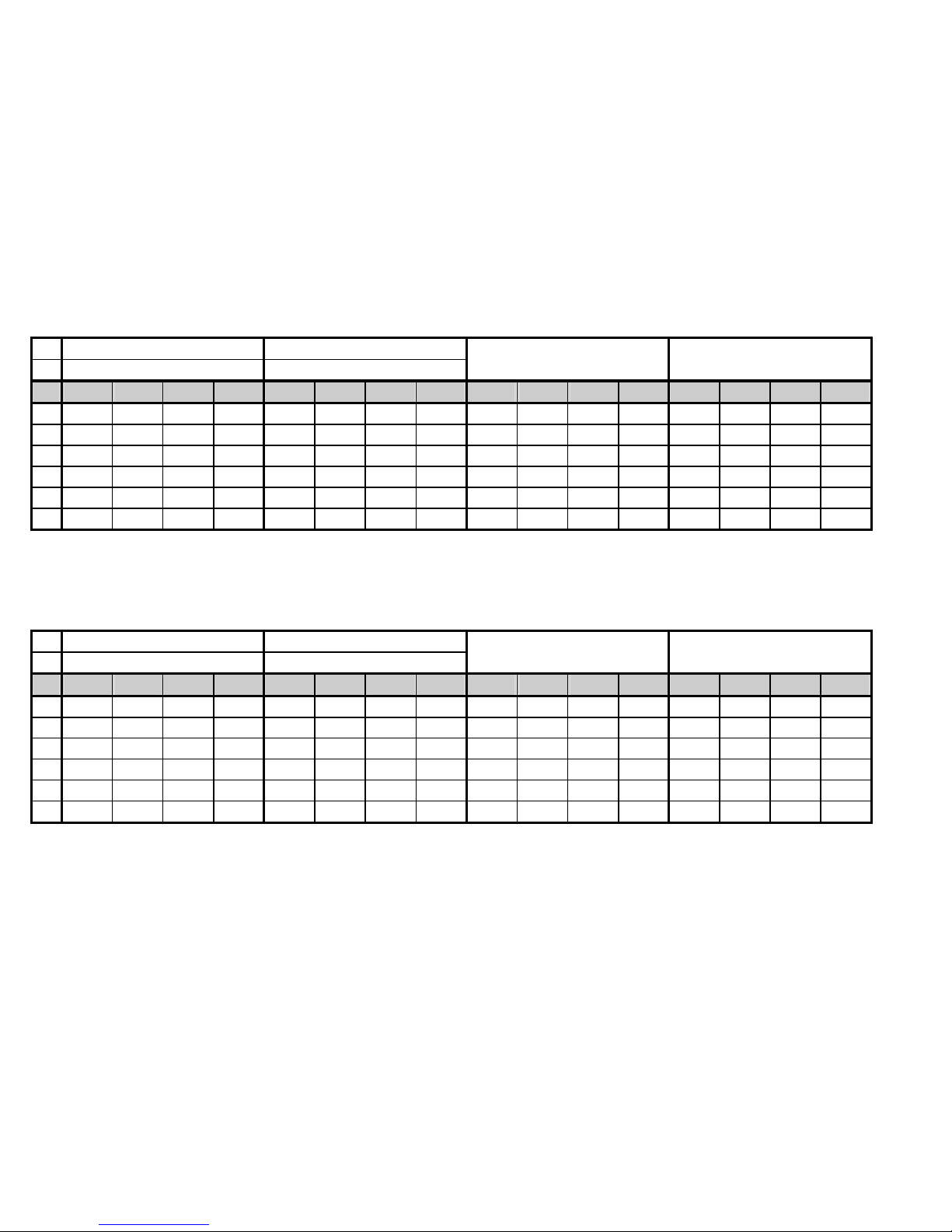
NIV128: NIVELCO device specific commands optimized for VOL measurement
EchoTREK 4-wire. EchoTREK 2-wire.
EasyTREK EasyTREK
NIVOTRACK NIVOCAP
P01 PV Base 3. Pos. 4. Pos PV Base 3. Pos. 4. Pos PV Base 3. Pos. 4. Pos PV Base 3. Pos. 4. Pos.
0 DIST LEV SR* Curr. DIST LEV SR Curr. DIST LEV SR Curr. % LEV 0 Curr.
1 LEV LEV SR Curr. LEV LEV SR Curr. LEV LEV SR Curr. LEV LEV 0 Curr.
2 LE% LEV SR Curr. LE% LEV SR Curr. LE% LEV SR Curr. LE% LEV 0 Curr.
3 VOL LEV SR Curr. VOL LEV SR Curr. VOL LEV SR Curr. VOL LEV 0 Curr.
4 VO% LEV SR Curr. VO% LEV SR Curr. VO% LEV SR Curr. VO% LEV 0 Curr.
5 FLO LEV SR Curr. FLO LEV SR Curr. - - - - - - - -
* SR (sensor range): Value of the difference in level between the „Maximum range” ( H=P04 ) and the „Minimum range” (dead zone - near blocking) in %
(empty tank: DIST=H 0%, full tank: DIST=”Minimum range” 100% ). Necessary for displaying the bargraph.
NIV129: NIVELCO device specific commands optimized for FLOW measurement
(TOT1 and TOT2 in float format)
EchoTREK 4-wire EchoTREK 2-wire
EasyTREK EasyTREK
NIVOTRACK NIVOCAP
P01 PV Base 3. Pos. 4. Pos PV Base 3. Pos. 4. Pos PV Base 3. Pos. 4. Pos PV Base 3. Pos. 4. Pos
0 DIST LEV TOT1 TOT2 DIST LEV TOT1 TOT2 DIST LEV 0 0 % LEV 0 0
1 LEV LEV TOT1 TOT2 LEV LEV TOT1 TOT2 LEV LEV 0 0 LEV LEV 0 0
2 LE% LEV TOT1 TOT2 LE% LEV TOT1 TOT2 LE% LEV 0 0 LE% LEV 0 0
3 VOL LEV TOT1 TOT2 VOL LEV TOT1 TOT2 VOL LEV 0 0 VOL LEV 0 0
4 VO% LEV TOT1 TOT2 VO% LEV TOT1 TOT2 VO% LEV 0 0 VO% LEV 0 0
5 FLO LEV TOT1 TOT2 FLO LEV TOT1 TOT2 - - - - - - - -
Page 51
prw2101a0600p_01
51 / 105
5.4.7. USER RS485
The MultiCONT User RS485 interface provides serial data transfer to the central
process controller computer or to a PLC. The following can be queried from
MultiCONT through the communication line:
system properties (MultiCONT configuration, relays, current outputs,
transmitters, errors, number of Universal Interface Modules, etc)
error list
device assignment to relays or current outputs
configuration of relays and current outputs
output values of the devices
The MultiCONT units have separate addresses so they can be connected into a
system. (max. 30 MultiCONT-s).
2 communication protocols are available:
HART 5 (default)
MODBUS RTU
USER RS485 80
Protocol
Parity
STOP bit
Protocol 82
HART prot.
MODBUS prot.
Parity 83
No parity
ODD parity
EVEN parity
STOP bit 84
1 STOP bit
2 STOP bit
5.4.8. Data Logger
Logger capability of the MultiCONT has two main parts with the following functions:
Trend logger: in a separate board in PED- and PRD- types. Storing can be done to the FLASH or the memory card. In case of trend logging the ID of the
transmitter, the primary value and three additional selectable values will be stored.
Time-controlled logging whereby an item is stored after a programmed time elapse or
Event-controlled logging whereby an item is stored a pre-set condition is fulfilled.
Two types of time-window logging can be used for flow-metering. Storing is done to the FLASH memory.
In case of “Time-window TOT” TOT is calculated in a selected time interval, monitoring the average, minimum and maximum value of the flow.
In case of “Time-window FM” the 8 highest values of flow are stored with time in a selected time interval.
Page 52
prw2101a0600p_01 52 / 105
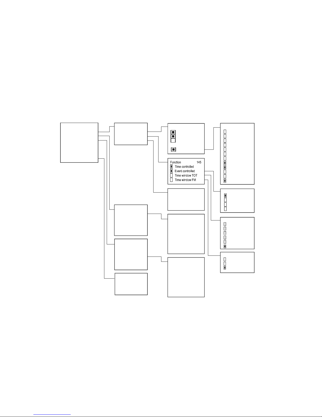
The time-windows are independent from the trend logger and even all four saving modes can operate at the same time (time/event-controlled, time-windows).
Time-window logger function can be used only for NIVELCO manufactured transmitters used in flow-metering mode.
SEA-380
LEP-100
SEA-340
SPA-360
:
Source 143
Setting
Show time window TOT
Show time window FM
Clear time window TOT
Clear log
Clear time window FM
Info
LOG
140
Source
Function
Parameters
Setting
141
Parameter 149
LP1 1234
LP2 5678
LP3 0030
SV
TV
QV
Current
Percent
Level
Level %
TOT1
TOT2
PV rate of change
Working
Head of flow
5:SPA-360
144
PV abs. change
PV % change
PV limit mon.
PV zone mon.
Event controlle d 146
1 hr
2 hrs
4 hrs
8 hrs
12 hrs
24 hrs
Time window TOT 147
1 month
6 months
12 months
Time window FM 148
01: I1
02: I2
:
12: I2n
Á
ramgenerátorok 27
:
1:SEA-380 151
T001: 2009.05.12 12:00
TOT: 12568m3
Qave: 35.6 l/s
Qmax: 58.6 l/s
2009.05.12 18:23
Qmin: 0 l/s
2009.05.13 08:02
01: I1
02: I2
:
12: I2n
Áramgenerátorok 27
:
3:SEA-340 142
Q1: 1256 l/s
2009.10.11-10:10
Q2: 1059 l/s
2009.05.10-09:45
Q3: 0959 l/s
2009.07.10-08:35
1: SEA-380
2: LEP-100
3: SEA-340
:
N: SPA-360
Source
143
1: SEA-380
2: LEP-100
3: SEA-340
:
N: SPA-360
Source
143
Entry number:
Overflow:
Status
Info
150
Page 53
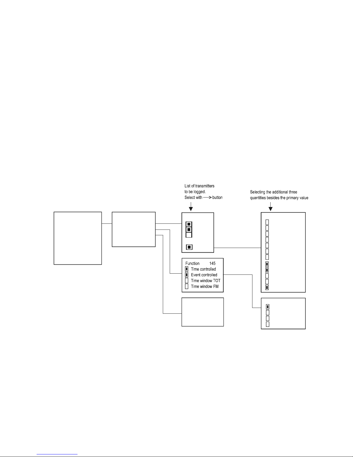
prw2101a0600p_01
53 / 105
5.4.8.1 Trend logger
Trend logger function is only available on PRD- and PED- instruments. Trend logging can be time-controlled (store an entry after a programmed time elapse) or
event-controlled (logging upon measurement changes). These two modes can be working simultaneously and conditions of the logging can be set from the menu
(programmed trend logging). Logged entry contains the necessary data to identify a transmitter, the time of the entry, the primary value of the transmitter, and three
additional menu-selectable values.
Data are stored into the FLASH memory in the first step. Capacity of the FLASH memory is 65000 entries. Then if data are stored into an SD (Secure Digital) card,
the capacity is depended on the SD card. The readout of the on-board memory can be performed via the USB port with an ordinary commercial USB cable (USB A-B
cable). Usage of the SD card is detailed in the chapter 5.4.8.4.
SEA-380
LEP-100
SEA-340
SPA-360
:
Source 143
Setting
Show time window TOT
Show time window FM
Clear time window TOT
Clear log
Clear time window FM
Info
LOG
140
Source
Function
Parameters
SD saving mode
Setting
141
Parameter 149
LP1 1234
LP2 5678
LP3 0030
SV
TV
QV
Current
Percent
Level
Level %
TOT1
TOT2
PV rate of change
Working
Head of flow
5:SPA-360 144
PV abs. change
PV % change
PV limit mon.
PV zone mon.
Event controlled 146
Page 54
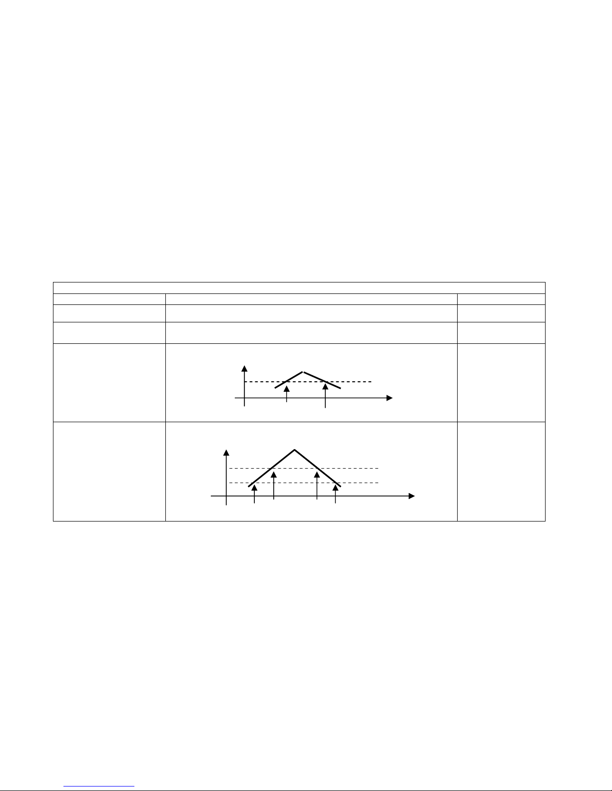
prw2101a0600p_01 54 / 105
For using the trend logging function, the following data should be set:
In the “Source” menu point the transmitter can be selected which measured value will be logged and the additional three values can be selected to be logged
besides the primary value.
In the “Mode” menu point the logging mode (time-controlled, event-controlled or both) can be selected.
In case of time-controlled logging mode in the “Parameters” menu point the logging interval should be entered into LP3 in minutes.
In case of event-controlled logging mode in the “Parameters” menu point LP1 and LP2 parameters should be set, according to the table below:
Event-controlled trend logging
Mode Operation Parameters
PV absolute change
Logging when (absolute) change of Primary value ( PV ) reaches the value in LP1
LP1
PV relative change in %
Logging when (relative) change of Primary value ( PV ) reaches the value in LP1 in
percentage
LP1
PV limit value monitoring
The logging monitors and stores the timestamps when Primary value ( PV ) exceeds
or falls under the value in LP1.
LP1
PV zone monitoring
The logging monitors and stores the timestamps when Primary value ( PV ) quits
from the zone defined by LP1-LP2, or when it returns into the zone.
LP1
LP2
In case of time-controlled trend logging the average of the selected values will be stored within the time interval which is set in LP3 parameter.
Mode and parameters of the logging are the same for all transmitters. Logging function commences when exiting the “LOG”/”Settings” menu point.
Besides the measurement values of the transmitters there are many events (which affect the operation of the whole system) stored in the trend logger regardless the
programming (see chapter 5.4.8.5).
LP1
Timestamps of logging
PV
LP1
LP2
Timestamps of logging
Page 55
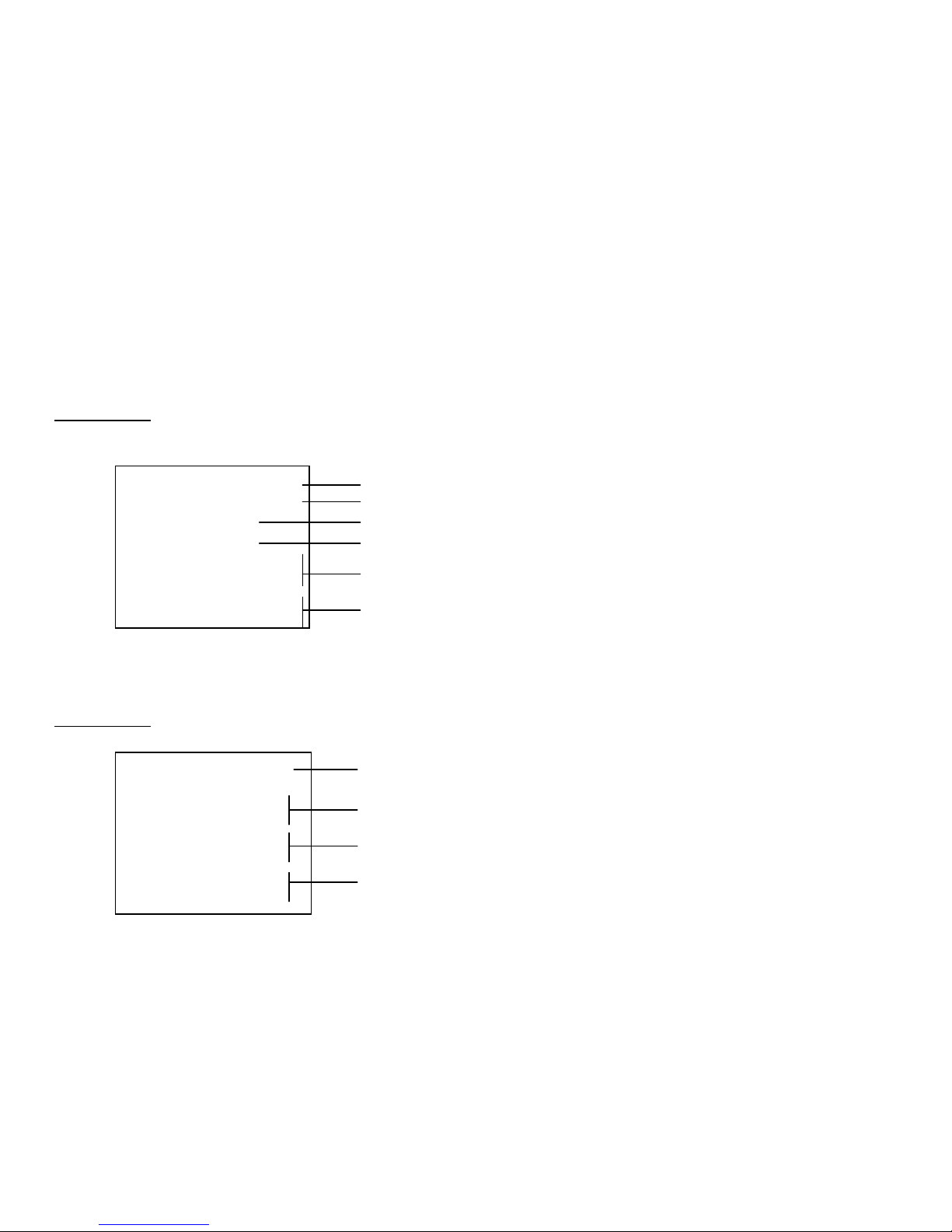
prw2101a0600p_01
55 / 105
Identifier of the transmitter
Number of „Time-window TOT” and time of start
Total flow
Average flow
Maximum flow with time
Minimum flow with time
2: SE-300 151
Tnnn: 2010.01.12-09:13
TOT: 15689 l
Qave: 12.56 l/s
Qmax: 54.23 l/s
2010.01.12-11:23
Qmin: 4.53 l/s
2010.01.12-13:56
2:SE-300 142
Q1: 458.56 l/s
2010.01.13-15:25
Q2: 418.13 l/s
2010.01.14-07:47
Q3: 356.98 l/s
2010.01.22-23:01
Identifier of the transmitter
Highest flow with time
2
nd
highest flow with time
3
rd
highest flow with time
5.4.8.2 Time-window TOT (Total flow logging)
This function is only available for NIVELCO manufactured transmitters operating in flow measurement mode (for this option NIV129 should be selected in
“Main menu”/”MultiCONT conf.”/”HART”/”Command set”). Within the selected time interval MultiCONT counts the total flow (TOT), the average flow (Qave) and
monitors the maximal and the minimal flow. Length of this time interval should be entered (in minutes) in LP3 parameter in the “Parameters” menu point. Up to 256
time-windows can be stored.
Read logging data: “Main menu”/”MultiCONT conf.”/”LOG”/”Show time window TOT”
, , OK and buttons are used for stepping in the list (OK moves down 10 lines, moves up 10 lines in the list)
T000 is the unfinished “Time-window 1”. T001 is the last finished time-window. Increasing nnn, the time can be incremented. nnn=0…255
5.4.8.3 Time-window FM (Flow Maximum logging)
This function is only available for NIVELCO manufactured transmitters operating in flow measurement mode (for this option NIV129 should be selected in
“Main menu”/”MultiCONT conf.”/”HART”/”Command set”). The 8 highest values of the flow are stored with time within the selected time interval in LP3 parameter in
the “Parameters” menu point.
Read logging data: “Main menu”/”MultiCONT conf.”/”LOG”/”Show time window FM”
and buttons are used for stepping in the list.
Page 56
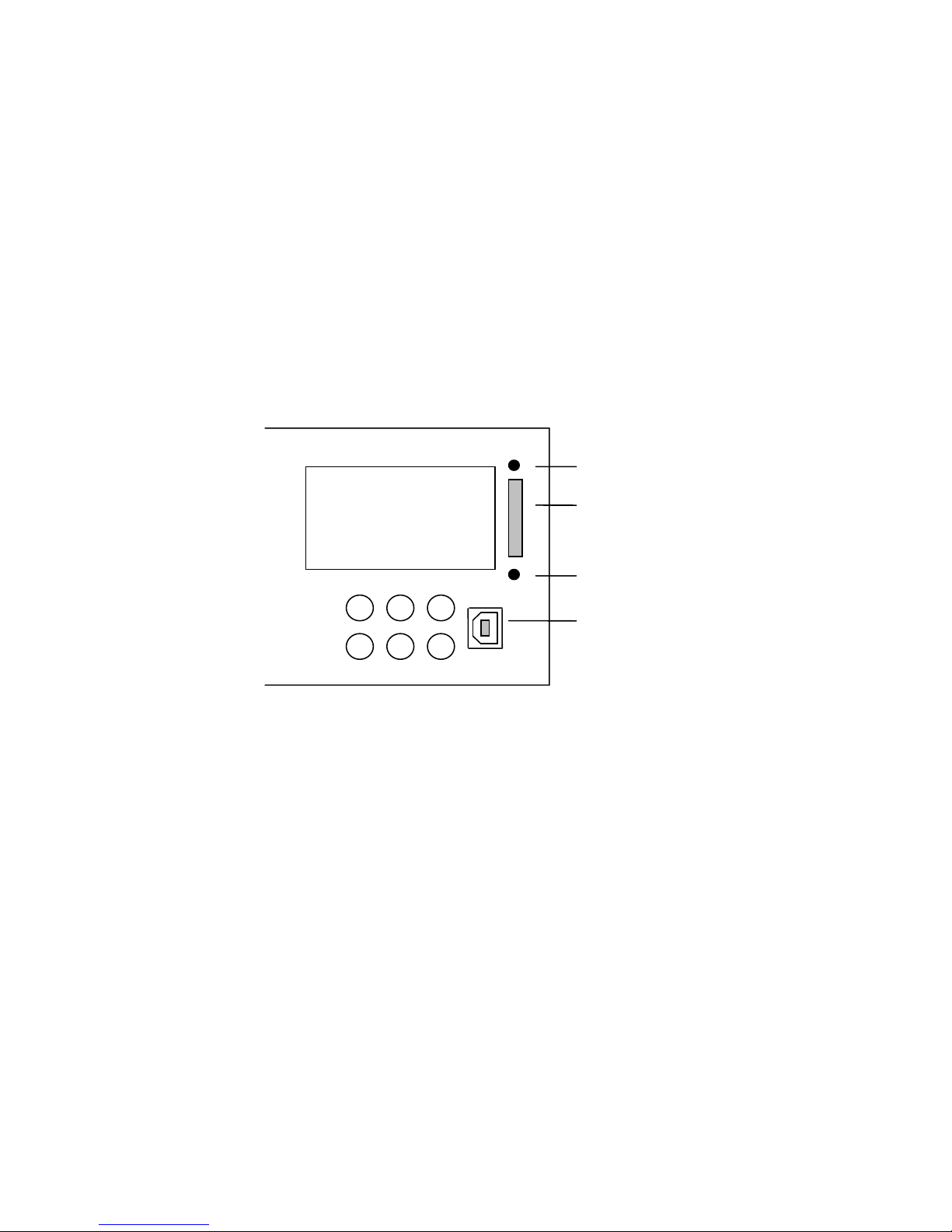
prw2101a0600p_01 56 / 105
5.4.8.4 Using a memory card for logging
Trend logging function is facilitated by a LOGGER unit connected to the front panel. It contains a FLASH memory chip and an SD (Secure Digital) card slot.
Communication between the central unit of the MultiCONT and the LOGGER unit is indicated by two LED-s on the front panel. The green LED (read) flashes when a
new logging entry is created, the red LED (wire) indicates when data are stored to the SD card. For storing data an SD (Secure Digital) memory card with maximum
2 GB capacity can be used. SDHC, MMC, Compact Flash, MiniSD, MicroSD and other types of memory cards are not available to use!
In case of PED- and PRD- type devices (which are able to trend logging) checking of the LOGGER unit is done when turning it on. Then the following box messages
will be shown on the display in accordance to the result of the logging procedure:
1:SPA-300 DIST 1 M
2.546 m
Red LED
SD card slot
Green LED
USB connector
Page 57
prw2101a0600p_01
57 / 105
This procedure is repeated in every turning ON/OFF and restart.
Then the measurement data are sent continuously to the LOGGER unit (flashing green LED indicates) and in case of fulfilment of the selected conditions
(see chapter 5.4.8.1) they are logged, which is indicated by the flashing red LED.
Capacity of the on-board FLASH memory is 65000 entries. When this memory is became full and there is no SD card in the card-reader, the old entries will be
overwritten so the logging will be performed by a “rotation”. Number of overflows can be read out in the “LOG”/”Info” menu point. When there is an SD card in the slot
the read and write process is done with the frequency selected in “LOG”/”Settings”/SD saving mode” menu point. Maximal capacity of the SD card is 2 GB. One entry
is about 200 byte, so this capacity provides storing entries more than a million.
The LOGGER unit of the MultiCONT senses automatically the inserted SD card. Then saving the FLASH memory into the memory card commences automatically.
State of this process can be followed in the trend bargraph. Before remove the memory card, the end of the write process (when the red LED does not flash) has to
be waited. In order to avoid removing the card during the write process, push the ESC and the buttons at the same time. Then the following box message will be
shown on the display:
From this moment the MultiCONT does not send any data for 10 seconds to the LOGGER unit (write is unavailable) and the
SD card can be safely removed.
SD card
can be removed
Everything is OK
Red and green LED-s are flashing until
this caption appears
LOGGER card is not working properly
In this case P-200 :LOG IP entry will be
created in the error-list
LOGGER PRESENT
LOGGER NOT PRESENT
Page 58

prw2101a0600p_01 58 / 105
5.4.8.5 File system of the SD card and file content of a logging entry
When inserting an SD card into the MultiCONT, content of the on-board FLASH memory is loaded automatically into the memory card (this is indicated by continuous
flashing of the red LED during write process). The LOGGER unit finds the last dated directory and examines if the files are more than 200 in this subdirectory. If not,
MultiCONT continues the write process. If there are more than 200 files, a new directory is created. One logging file can contain max. 1000 entries, but new logging
files are created when turning ON/OFF, restart of the MultiCONT and exiting from the LOG menu.
After finishing the saving process to the SD card, data are able to open in any PC with appropriate SD card-reader. The logging file is a special TAB articulated text
file, which can be read with any spreadsheet application if necessary.
Name of the sub-directories on the card: PRddd where ddd=001…999
Name of files in the sub-directories: PRffffff.TXT where ffffff=000001…999999
The created file-system looks like in the following:
PR001 1
st
directory
PR000001.TXT
PR000002.TXT
PR000003.TXT
.
PR000200.TXT
PR002 2
nd
directory
PR000201.TXT
PR000202.TXT
.
PR000252.TXT
PR003 3
rd
directory
PR000253.TXT
PR000254.TXT
.
Page 59

prw2101a0600p_01
59 / 105
The PRffffff.TXT named logging files in the directories consist of two main parts: header and data field. The header contains the following information:
NIVELCO DataLogger Ver.:1.08 MultiCONT Ver.:01.02.02 << DataLogger and MultiCONT version
Date:2001.01.01 01:02 << Date of file creation
Data field contains the following data rows:
Title
Description Example
Head Logging entry code (LG = logger, ST = status, SD = mem.card operation, ER = error message)
Date Logging entry date 2010.05.07
Time Logging entry time 13:01:40
Type Logging entry type (see Type codes) 2
Dev List-tag of the source device 3
Addr HART Long address of the transmitter 151.30.2555904
Tag Short tag SAP-300
Err. Error 0
Status Status 0
Curr1 FLOW
Value1 125.67
Unit1
Primary Value
m3/h
Curr2 LEV
Value2 0.567
Unit2
Selected additional 2
nd
quantity
m
Curr3 TOT2
Value3 12345678
Unit3
Selected additional 3
rd
quantity
m3
Curr4 Work
Value4 1548
Unit4
Selected additional 4
th
quantity
h
Page 60
prw2101a0600p_01 60 / 105
Comments:
If logging entry type is not 2, then MultiCONT is the source ( DEV=255, TAG=P-100, Error=0, Status=0), instead of the PV and the three additional selected
values use NAN (no data) caption can be read.
Insertion of SD card: SD 2010.05.07 13:01:40 SD pushed
Removal of SD card: SD 2010.05.07 13:01:40 SD pulled
In case of ST entries, the selected values in LP1, LP2 and LP3 parameters can be read out from Value1, Value2 and Value3.
In case of ST entries the following codes are in the Type and Dev columns:
Type:
B7 B6 B5 B4 B3 B2 B1 B0
00=absolute value change
01=value change in %.
10=limit value monitoring
11=zone monitoring
1=event-controlled ON
1=time-controlled ON
Dev:
B7 B6 B5 B4 B3 B2 B1 B0
SD saving mode
000=
1 row
001=
8 rows
010=
16 rows
011=
32 rows
100=
64 rows
101=
128 rows
Number of transmitters to be logged
( LOG/Settings/Source )
Page 61

prw2101a0600p_01
61 / 105
The following codes can be in the type code column:
Type code Description Comments
0 Hardware reset Turning ON
1 Software reset Device restart from menu
2 Entry of measured value Programmed TREND logging entry
3 MultiCONT CRC altered
Settings of MultiCONT have changed. CRC calculated when entering
Main menu differs from the CRC calculated when quitting the Main
menu.
4 TOT1 clear Clearing TOT1 from a NIVELCO instrument used for flow-metering.
5 TOT2 clear Clearing TOT2 from a NIVELCO instrument used for flow-metering.
6 MultiCONT clock set
7 Transmitter ( DEVICE ) default load Loading default settings of the transmitter from menu
8 MultiCONT default load
9 Logger delete from menu
10 MultiCONT error-list clear
11 Transmitter program CRC altered
MultiCONT checks CRC when entering and quitting remote
programming mode. Logging entries are created when the two CRC
differs.
12 New list saved after ( DEVICE ) detection
253 Instrument respond error
Transmitter does not respond to the entered commands, it will be stored
also in the error-list
254 Instrument inactive The instrument selected for logging is in inactive state
Page 62
prw2101a0600p_01 62 / 105
5.4.9. Secret code
The viewing and modification of MultiCONT settings can be protected with a secret code differing from 00000000.
If there is a password, the following symbol appears left of the menu identifier, and flashes after being unlocked.
The password remains temporarily unlocked until returning to the measuring process.
No access
Scope
46
All
Modify
"Password" is 00000000,
no restriction
The "Password" is not 00000000,
To enter and modify a password is needed
Password modification permission is denied
thus unable to modify "password"
Go back to Unlock menu
If "Password" is unlocked the key flashes,
if there was no password, there is no key
"Password" can be deleted by typing 00000000
Access to view parameters but not to modify
Unlock
Modify
Scope
Password
44
Unlock please
Press OK
No Code
Press OK
Unlock
00000000
Modify
00000000
Password protected MultiCONT
Page 63
prw2101a0600p_01
63 / 105
5.4.10. Language
This is where to select the language used during measurement and programming.
The selected language will be switched to immediately.
Language 43
English
German
French
Hungarian
select using
Default: english
5.4.11. Background lighting
The background lighting of the display can be modified here.
Backlight 36
Low
Auto
High
In auto mode, pressing any button sets the backlight to "high".
10 s after the last button was pressed, the backlight turns off
Page 64
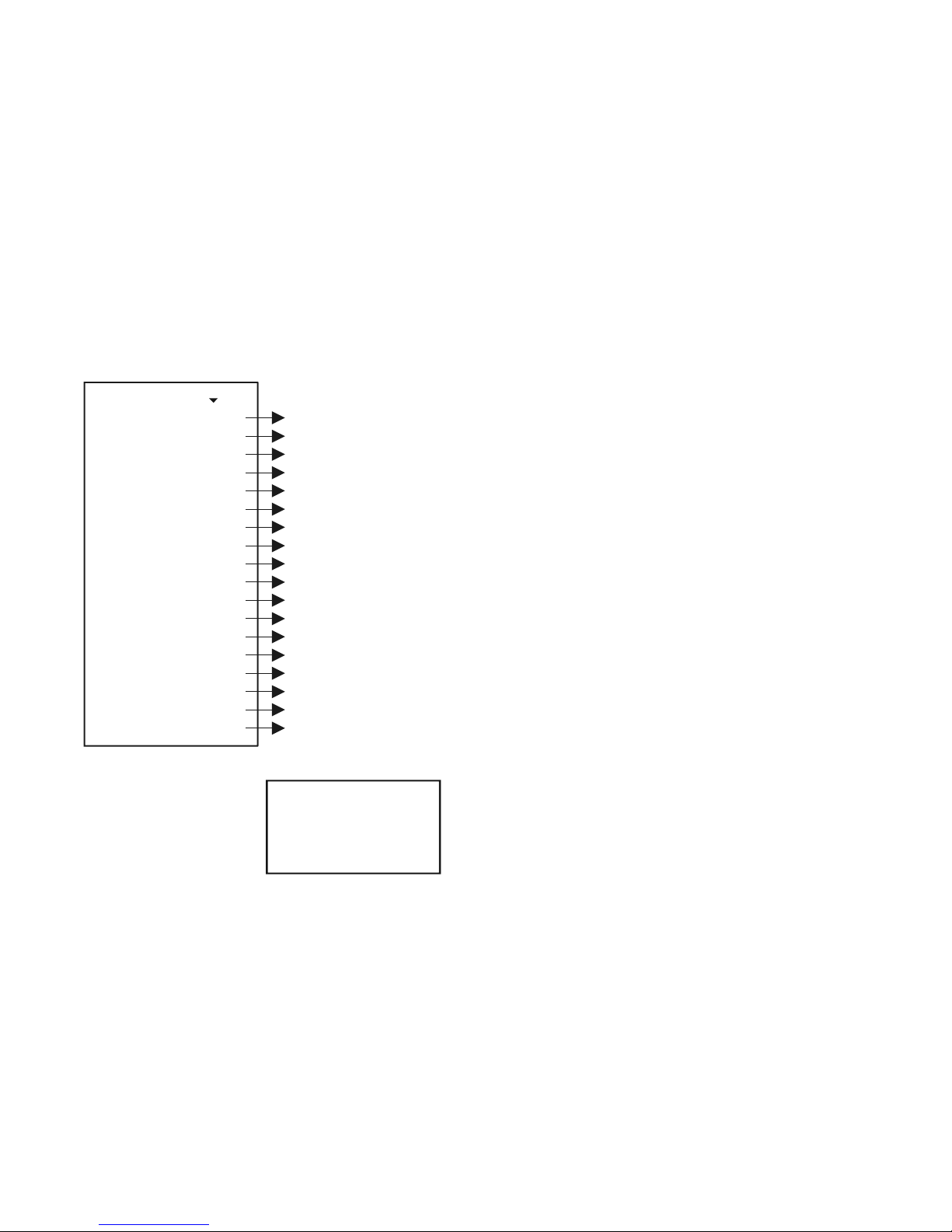
prw2101a0600p_01 64 / 105
5.4.12. Report:
This provides information about the system structure. This displays the number of devices (transmitters), relays, current outputs, and modules in the system, and also
the number that can be handled. Binding is when a relay or current output is assigned to a device.
Report 53
Devices:
UIM-s
Relays:
Current outs:
Inputs:
U485:
M485:
Bindings:
Typ e:
SW type:
SW version:
Serial:
Date:
Working:
Power cnt:
Temp min .:
Temperature:
Temp max .:
002/015
000/032
004/064
002/016
000/000
NO
YES
005/100
PEC2M9
01
01.00
B9718160
2005/11/15
6/18/59
224
18°C
22°C
35°C
2 devices (transmitters) in the loop, max. 15
No. of Universal Interface Modules (PJK-100)
No. of relays (64 = sum of maximal internal and external relays)
No. of current outputs
Other inputs
RS485 u interface
RS485 m interface (needed for UIM functioning)
No. of bindings
Type of MultiCONT
S
ser
odule
oftware type of MultiCONT
Software version of MultiCONT
Serial no. of MultiCONT processor
Date of MultiCONT software update
MultiCONT work time (days/hrs/mins)
No. of MultiCONT "power-on"s
MultiCONT min. temperature
MultiCONT actual temperature
MultiCONT max. temperature
5.4.13. Prog CS
When exiting the menu the device
generates a Frame Check Sequence from
the settings (EXCLUSIVE-OR operation of
bytes)
Prog CS
81
129
Page 65
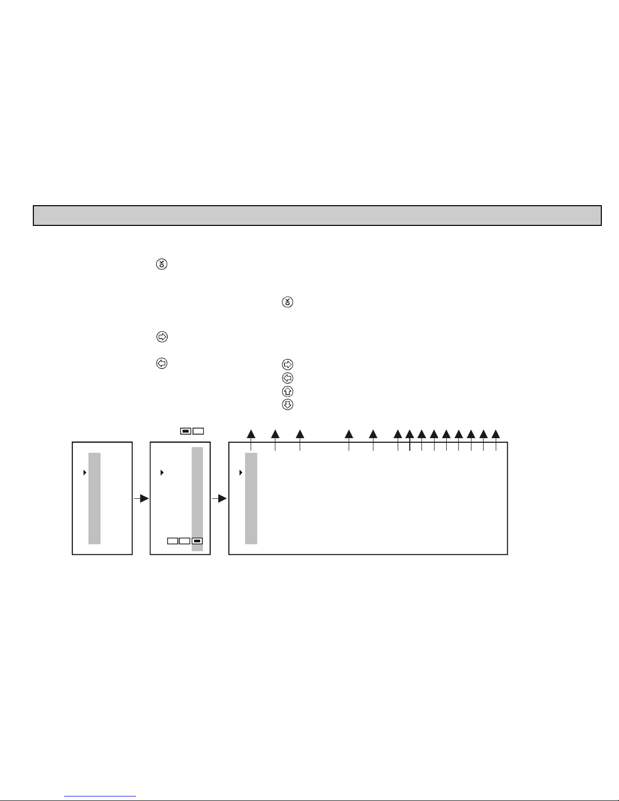
prw2101a0600p_01
65 / 105
5.5. PROGRAMMING DEVICES
Devices 06
02: SE300
01: ST300
Main menu
01
Current outs
Devices
Relays
"OK"
"OK"
Remote programming
Short TAG
Short address
Message
Description
Date:
Final ass. number
Factory ID
Device type ID
SW version
HW version
Device ID
Major revision
Device revision
Device: SG300
07
Programming the device and querying parameters
see: chapter 5.6.*
Short TAG
use and after press
Short address** (1...15), used during detection
will search for the device with this address
Secret code* not needed for modification
Modification should be done with care
Arbitrary text assigned to the device
(usually related to operation, max 32 char)
Arbitrary text assigned to the device
(usually related to the material, max 16 char)
Date assigned to the device
Factory setting = 0
Factory ID, for NIVELCO devices = 151
Device type ID
Software version of the transmitter (see manual)
H version of the transmitter (see amnual)
To query and modify the
ardware
Manufacturer's electronic serial number
HART revision
0
Device selection with and buttons, then press to
query and modify parameters.
Device is active
Device is not active, but can be programmed as if it were active
03: G300S
* In case of the NIVELCO non-compatible transmitters, only the assigned 4-20 mA values and damping time can be
programmed”.
** In this menu point the short address of the device will shown when pressing OK button. Detected “Short address”
is stored in the operative memory, turning off the device the memory content is erased. In case of this “??” will
appear. It has no effect on the operation, because communication is performed via “Long address” (cannot modified)
after the detection. The transmitter will have the modified address at the next detection!
Page 66
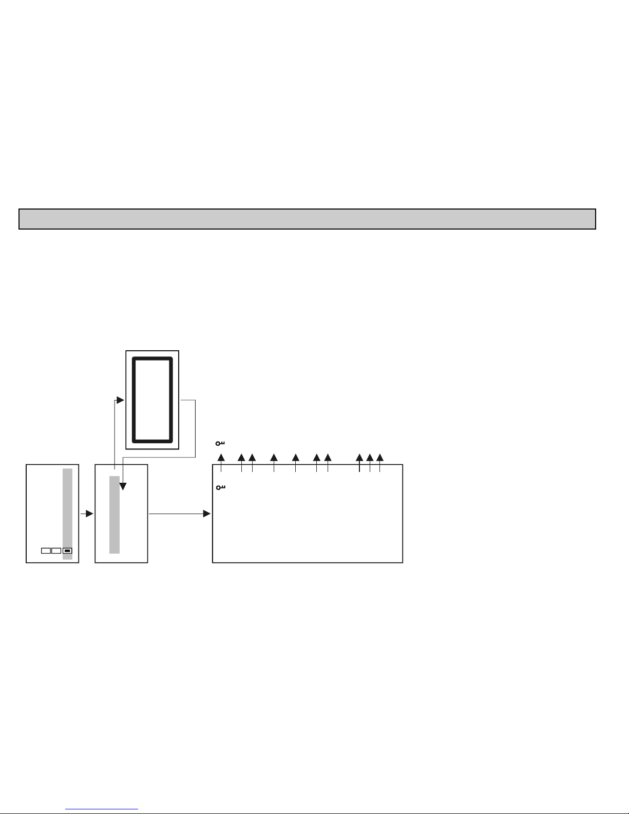
prw2101a0600p_01 66 / 105
5.6. REMOTE PROGRAMMING
Select the device to be programmed as described above.
Secret unlock
Secret mod.
App. parameters
Parameters
Linear table
Echo
Clear TOT1
Factory defaults
Service
HART protection
Press OK
"OK"
"OK"
Remote programming
Short TAG
Short address
Device: SG300
07
"key" shows that the device configuration is protected by a
(see programming manual of the device)
Unlocking the
Entering or changing the To change an existing code
the old one should be unlocked!! *
Parameter for NIVELCO instruments for selecting the
unit to be used (Metric: m, cm, US: ft, inch)
Querying and modifying the parameters of the device. **
If the device is password protected parameters are only readable. *
Editing the linearisation table (see chapter 5.6.1.)
Draws the Echo-map for ultrasonic transmitters***.
(returns with "unknown DEV/comm" error for devices where
this is not d efined)
Clears TOT1 for with flow mea surement function devices
"Password"
"Password"
"Password".
Return to default settings.
Clear TOT2, temper ature calibration, DIST calibration,
write Device ID (service code is needed for access)
Devices
06
02: SE300
01: ST300
03: SG300
Remote programming
"OK"
"OK"
Quit programming mode
or wait for automatic
exiting of PROG mode
(max. 30 min)
08
The device is in PROG mode,
remote programming is not allowed.
*, **, *** See next page for explanation
Note: Content of this menu is depended on the type of the transmitter!
For example: MicroTREK see: appendix 6.
LEP-100 see: appendix 7.
Page 67
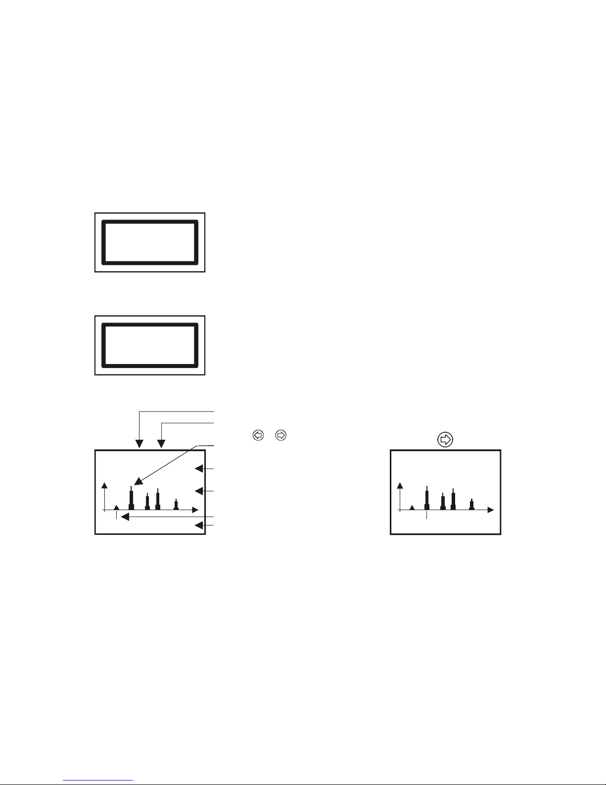
prw2101a0600p_01
67 / 105
* If the access is denied the following message appears.
Unlock please
Press OK
After entering a valid code press OK.
** Parameters entered during remote programming via MultiCONT will be sent without being checked to the device where
the data is checked. In the event of bad parameter value, or if the given parameter is not defined in the given device, then
the following message appears:
HART logical error
Press OK
To correct the problem see the User’s Manual of the respective device
(transmitter)
*** Explanation of the Echo Map of ultrasonic transmitters
On enter:
13Echo 5 1
1.40 m -3.2 dB
No. of echoes
No. of selected echo (on enter 1),
select with or
Measured echo is blinking
0.70 m -17.5 dB
A
mplitude and distance of the
measured (blinking) echo
The echo-map
Selected echo
marking
amplitude and distance
after pressing button:
13Echo 5 2
1.40 m -3.2 dB
1.40 m -3.2 dB
Note!! The displayed data corresponds to the moment of entering into the menu.
The flashing echo is the one used by the transmitter to measure distance. To refresh the display press ESC then OK.
Page 68
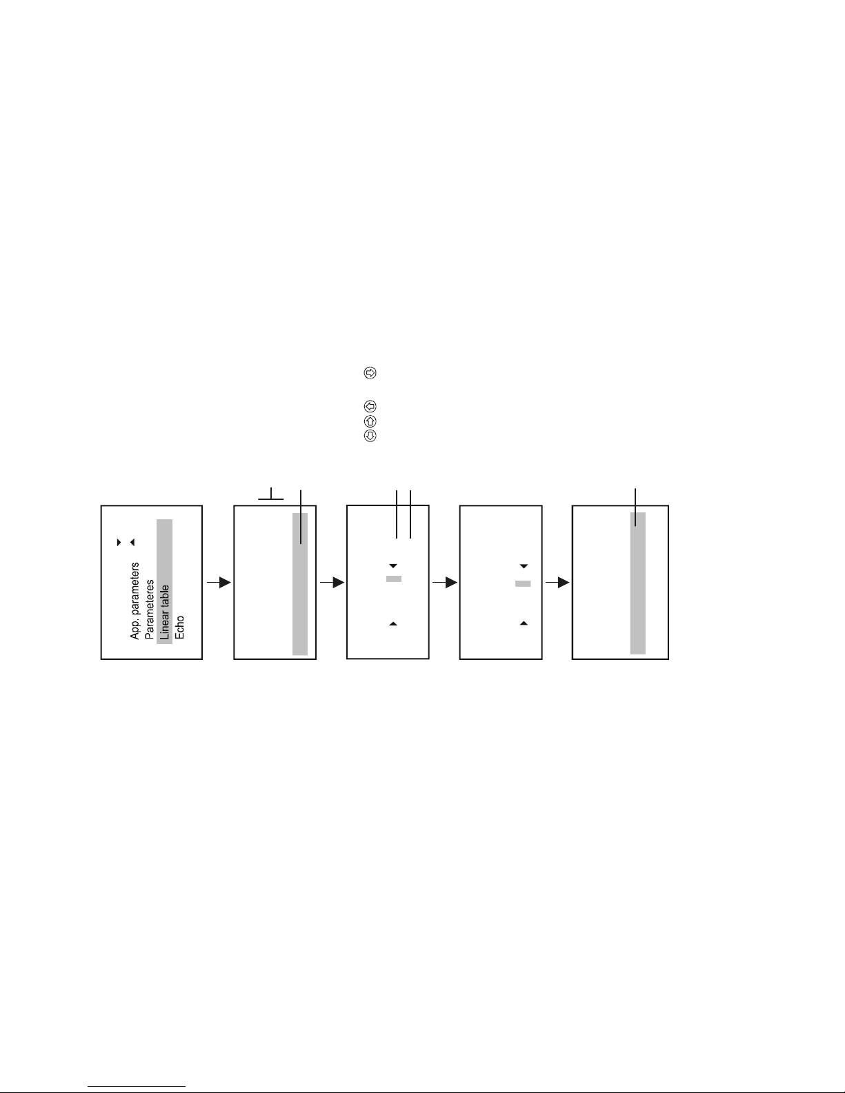
prw2101a0600p_01 68 / 105
5.6.1. Editing the linearisation table
Remote program
08
Linear table
12
01: 0.000 0.000
02: 1.520 125.540
3: (Lin. 0 )
Lin. 03
Lin. 03
1.980 m
+0259.300 m /s
3
Linear table
12
01: 0.000 0.000
02: 1.520 125.540
03: 1.980 259.300
( )
Lin. 04
"OK"
"OK"
"OK"
"OK"
Table with two rows
Data pair to be edited
Edit of 3 row has finished
rd
Edit using and buttons
Editing left sided element of the data pair
Right sided element of the data pair
+0001.980 m
0.000 m /s
3
Warning! For the transmitter to compute the measurement results using the linearisation table, linearisation has to be enabled in parameter P47
(See the Installation and Programming Manual of the given transmitter)
Page 69
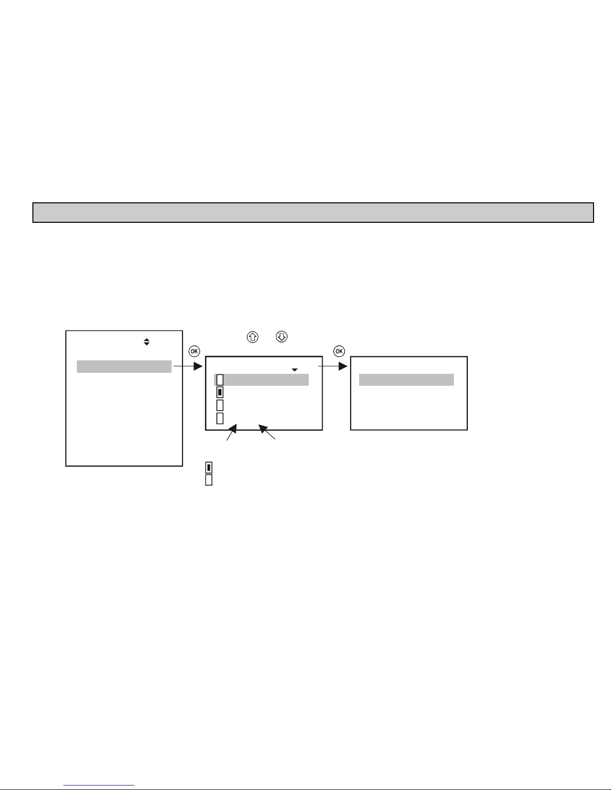
prw2101a0600p_01
69 / 105
5.7. RELAY CONFIGURATION
First of all it is recommended to decide which relay is to be assigned to which device(s), and to which measured value (PV=primary value, SV=secondary value, …. )
in Main menu/Relays/ Program/Source. Relays can be assigned to one or more sources (difference, average). Secondly the relay function should be selected in Main
menu/Relays/ Program/Function. Finally the parameters have to be specified in Main menu/Relays/Program/Parameter such that the dimensions of RP1 and RP2 are
determined by the devices assigned to them. Thus if the chosen value is LEVEL [m] then the RPx parameters also have to be entered in LEVEL [m].
5.7.1. Relay Selection
It is impossible to enter the relay menu if the system does not contain a single relay. The number of relays in the system can be viewed under Main menu/MultiCONT
config/ Report. (See chapter 5.4.12.)
Devices
Relays
Current outs.
Inputs
UIM-s
Default config
MultiCONT config.
Save config
Load config.
Main menu
05
Select using and
Relays 18
01: R1_IN
02: R12
:
12: R12n
01: R1_IN 19
Program
Short TAG
Info
List number
of relay
Relay ID
Short TAG
Active
Inactive, de-energised relay
Page 70
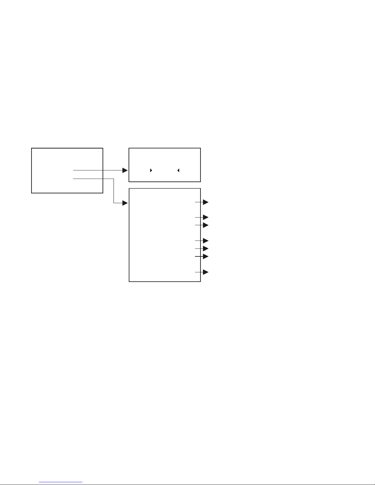
prw2101a0600p_01 70 / 105
5.7.2. Properties of the selected relay
The refreshing of “Cycle”, “Workking”, “Input” and “Output” takes place continuously in the case of the internal relays.
01: R1_IN 19
Program
Short TAG
Info
Short TAG
R_IN_1
25
Cycle:
Working:
Input:
Output:
ID:
Parent:
Location:
1789
67
0.589
BE
9729718161
9728718160
Internal
Info
74
Number of state changes of the relay
The ener
g
isation and release are each considered a different state
Relay energisation time
The value that the relay state was calculated from
(if RP1...RP3 are known)
Actual state of the relay
Relay ID number
In case of an internal relay, the
[ h ]
MultiCONT's ID,
if not then the module's ID
Location of the relay (Internal=in MultiCONT,
External=in an external module)
Page 71
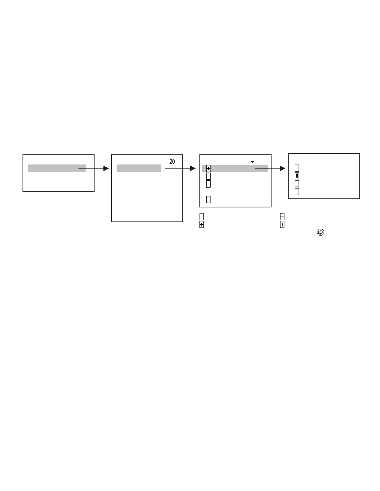
prw2101a0600p_01
71 / 105
5.7.3. Relay programming
5.7.3.1 Source selection
One or more devices can be assigned to one relay.
19Relay: R1_IN
Program
Short TAG
Info
Program
Source
Function
Parameter
Invert
Clear TOT
Update TOT
Te s t
10
2
3P8
: SE30
: SC380
: S 3 0
:
n: ST-300-1
Source 21
Not assigned
Assigned with a "+" sign
1: SE300
PV
SV
TV
QV
57
–
Modify using
A
ssigned with a " " sign
Assigned by averaging
In the above example, Relay R1_IN is controlled by the difference of the secondary values of SE300 and SP380. In case of a single unit, the sign is indifferent, in fact,
average might as well be selected. In case of the selection of multiple devices, control depends on the result of the mathematical sum. If in the case of selected
multiple devices the dimensions of the quantities are different, the unit will display an error message. Upon selelcting the quantity, confirm that the appropriate HART
command has been seleceted for the device (See Main menu/MultiCONT config/HART / command set, see chapter 5.4.5.5)
Page 72
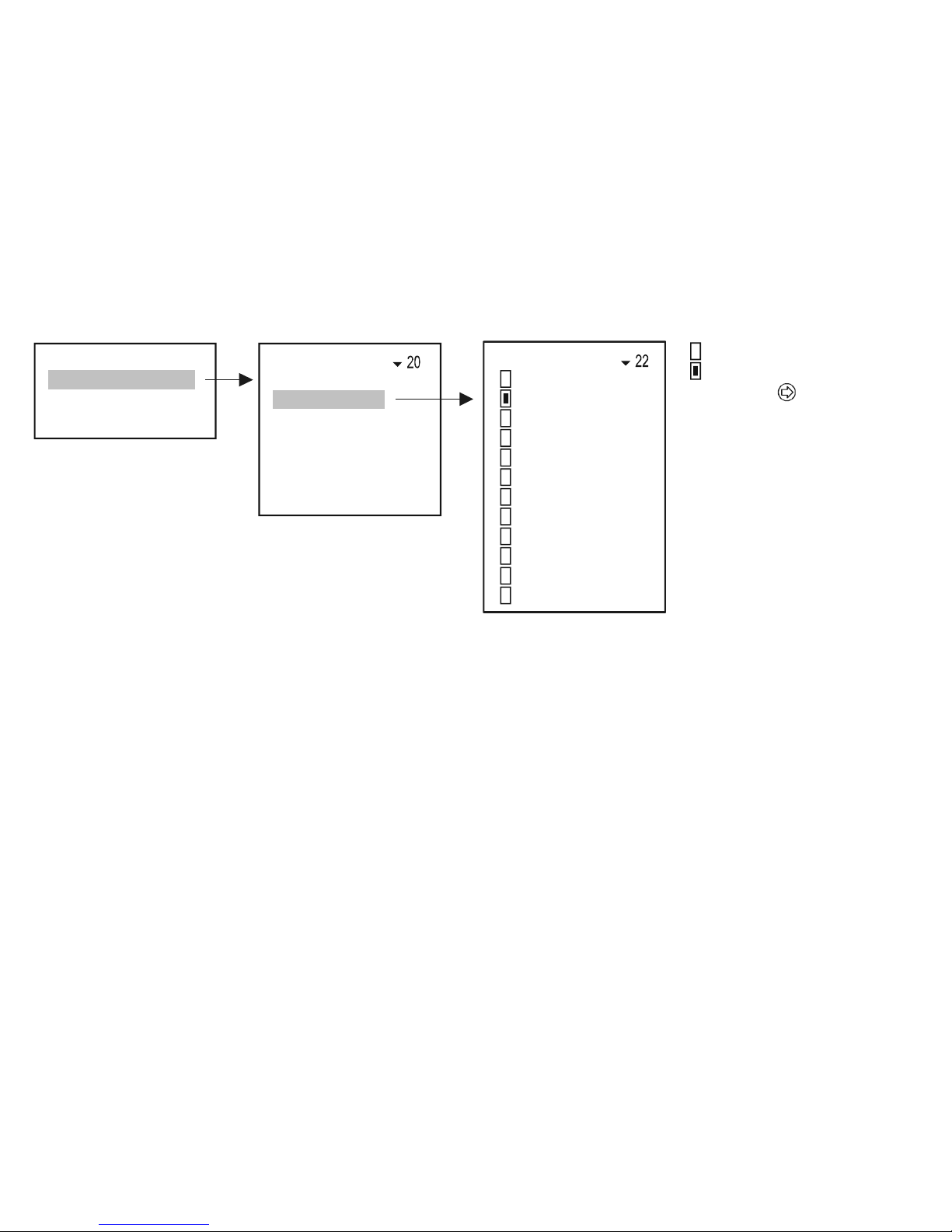
prw2101a0600p_01 72 / 105
5.7.3.2 Function
Function
Hyst.
A
larm
Alarm, K
Alarm, G
Window
Window, D
Error
Impulse, F
TOT 1
Alt., S
Sequential
PV rate of chan
g
e
19Relay: R1_IN
Program
Short TAG
Info
Program
Source
Function
Parameter
Invert
Clear TOT
Update TOT
Te st
Not selected
Selected
Select usin
g
Page 73
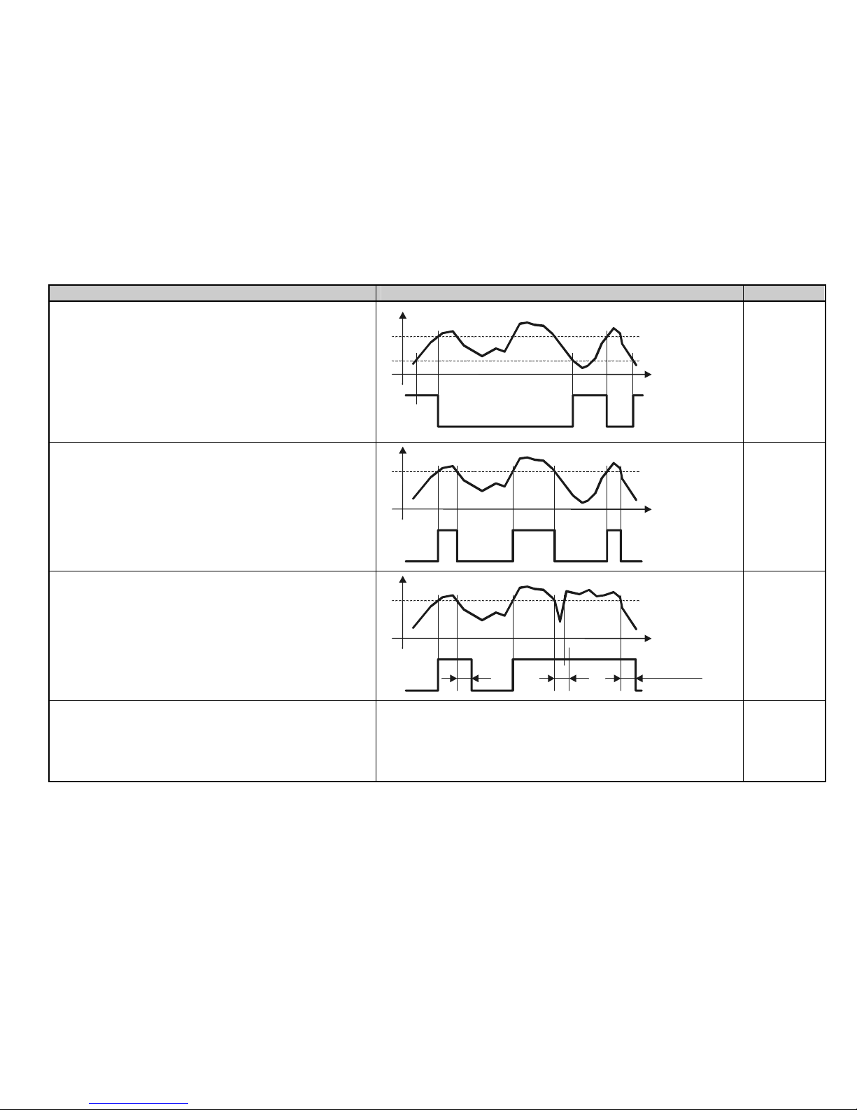
prw2101a0600p_01
73 / 105
OPERATING MODE FUNCTION PROG. PAR
Hysterisis. (2-point control)
Default: filling with energized relay:
Invert = OFF,
above RP1 the relay will be de-energized below RP2 it will be
energized
Inverted operation: by interchanging RP1 and RP2
or by selecting Invert = ON
Main menu/Relays/Program/Invert
If RP1 = RP2 then the upper alarm function is enabled
RP1
RP2
t
Energised
De-energised
Relay
RP1,
RP2
Alarm
Default: Invert = OFF
Below RP1 relay will be de-energized
Inverted operation (relay will be energized below RP1) or by
selecting Invert = ON
Hysterisis = 2.5% of RP1
If RP1 = 0 the relay will be constantly energized
RP1
t
Energised
De-energised
Relay
RP1
Alarm K (with delayed switching)
Default: Invert = OFF
below RP1 relay will be de-energized using delay in RP3
(Factory default t= 0 sec )
Delay can be set under RP3 in sec
RP1
t
Energised
delayK
De-energised
Relay
K K
RP1,
RP3
Alarm G (group ALARM)
Default: „Invert =Off”
Relay get de-energized if the condition (measured value is less than RP1)
is fulfilled in case of any transmitters assigned to the relay.
Hysteresis: 2.5% of RP1
Operation can be inverted with Invert =On switch
(Relay get de-energized if the measured value is more than RP1)
RP1
Page 74
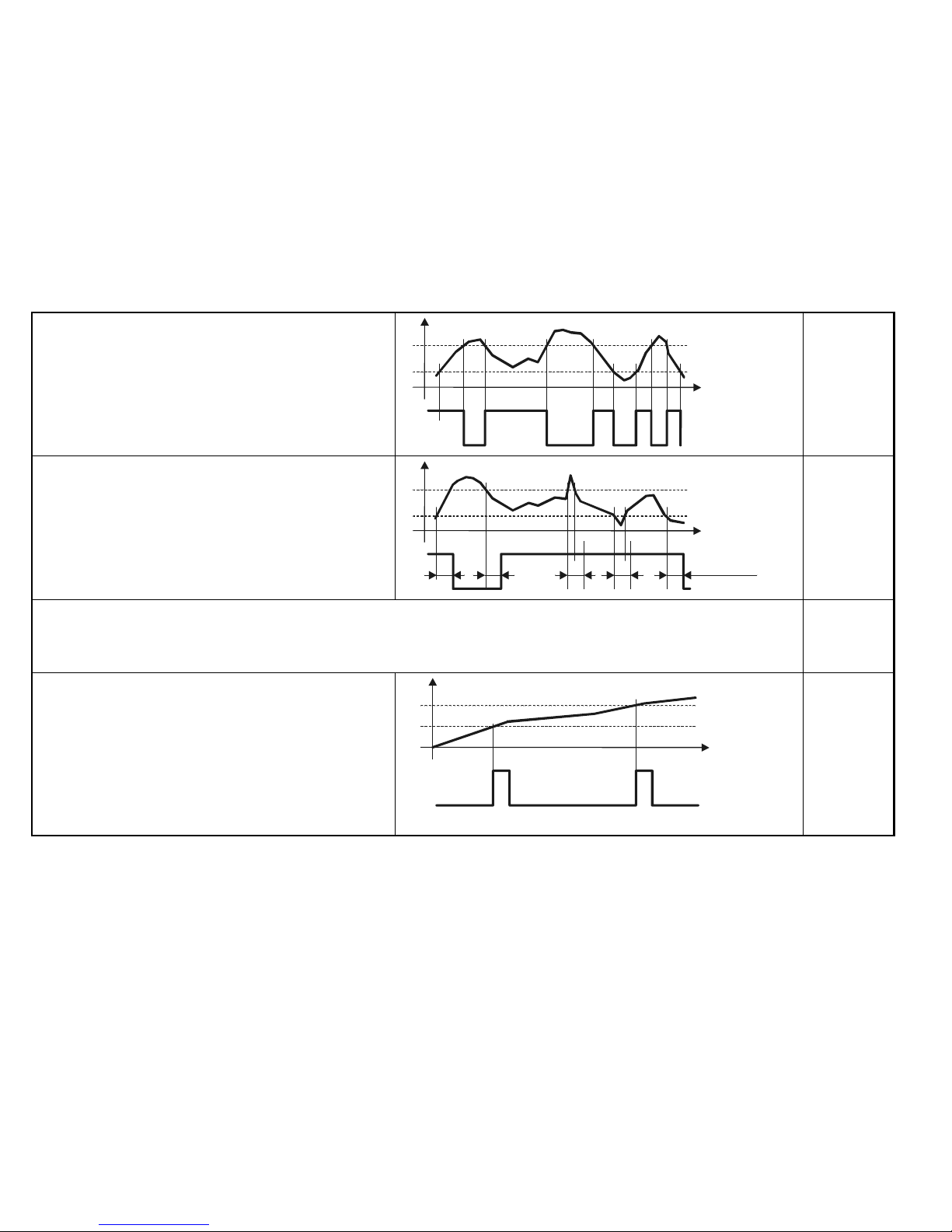
prw2101a0600p_01 74 / 105
Window (window comparator)
Default: Invert= OFF
Between RP1 and RP2 relay will be energized
Inverted operation (Between RP1 and RP2 relay will be de-
energized)
or by selecting Invert = ON
RP1
RP2
t
Energised
De-energised
Relay
RP1,
RP2
Window D (comparator with delayed switching)
Default: Invert = OFF
Between RP1and RP2 relay will be energized using delay in
RP3 (Factory default t= 0 sec )
Inverted operation (Between RP1and RP2 relay will be de-
energized )
or by selecting Invert = ON
RP1
RP2
t
Energised
DelayK
De-energised
Relay
K KKK
RP1,
RP2,
RP3
Error
Default: Invert = OFF
In case of error relay will be de-energized. RP3=0 for any error; RP3=n for error of code n
Inverted operation (in case of error relay will be energized ) or by selecting Invert =ON
RP3
Impulse F
Default: Invert = OFF
relay will be energized for appr. 200ms for each unit volume
set in
RP3
Operation can be inverted by selecting Invert = ON
Programming error will be displayed if:
more than one device (transmitter) is marked as source
RP3 = 0
t
De-energised
Relay
TOT1
20
10
Energised
RP3=10
RP3
Page 75
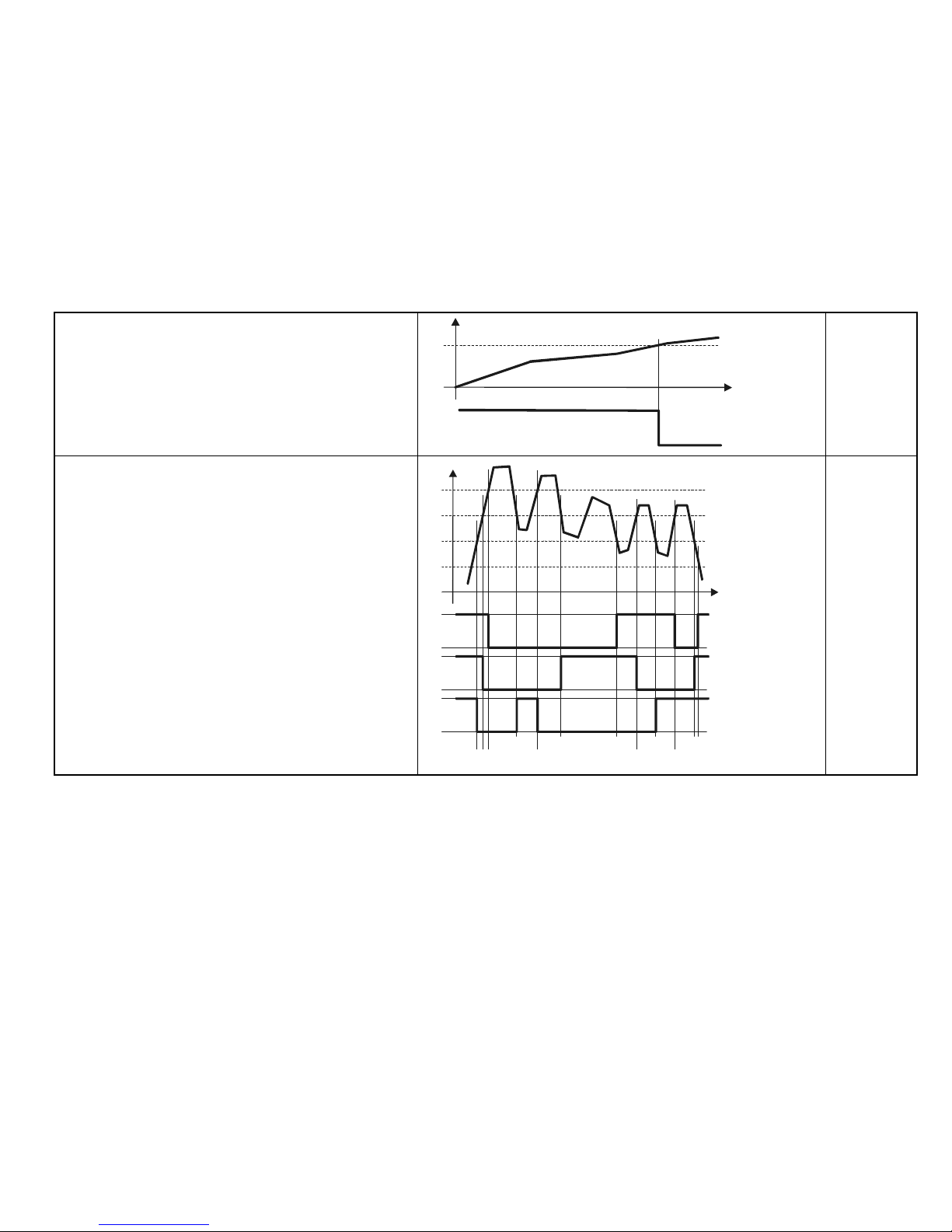
prw2101a0600p_01
75 / 105
TOT1
Default: Invert = OFF
relay will be de-energized when TOT1 reaches value in RP1
Operation can be inverted by selecting Invert = ON (relay will be
energized)
t
Energised
De-energised
TOT1
20
RP1=20
Relay
RP1
Alt (optimized pump control)
Default: Invert = OFF
More relays (max 8) can be assigned to one source (transmitter)
and they are controlled such that the switching number will be the
same for all of them.
In this case the connected relays will be energized and deenergized one after the other irrespective of which relay’s
conditions are fulfilled.
As in the diagram, relays programmed in this manner operate in
the following sequence for:
Mode: Alt S
1 23 1 23 Energised
123 1 2 3 De-energised
Mode: Hysterisis
3 32 2 21 Energised
123 3 2 2 De-energised
t
R3
Energised
De-energised
Relay
RP1
RP2
R1
RP1
RP2
R3
RP1
RP2
R2
R1
Energised
De-energised
Relay
R2
Energised
De-energised
Relay
Energised
De-energised
1
123 1
2321
3
23
RP1,
RP2
Page 76
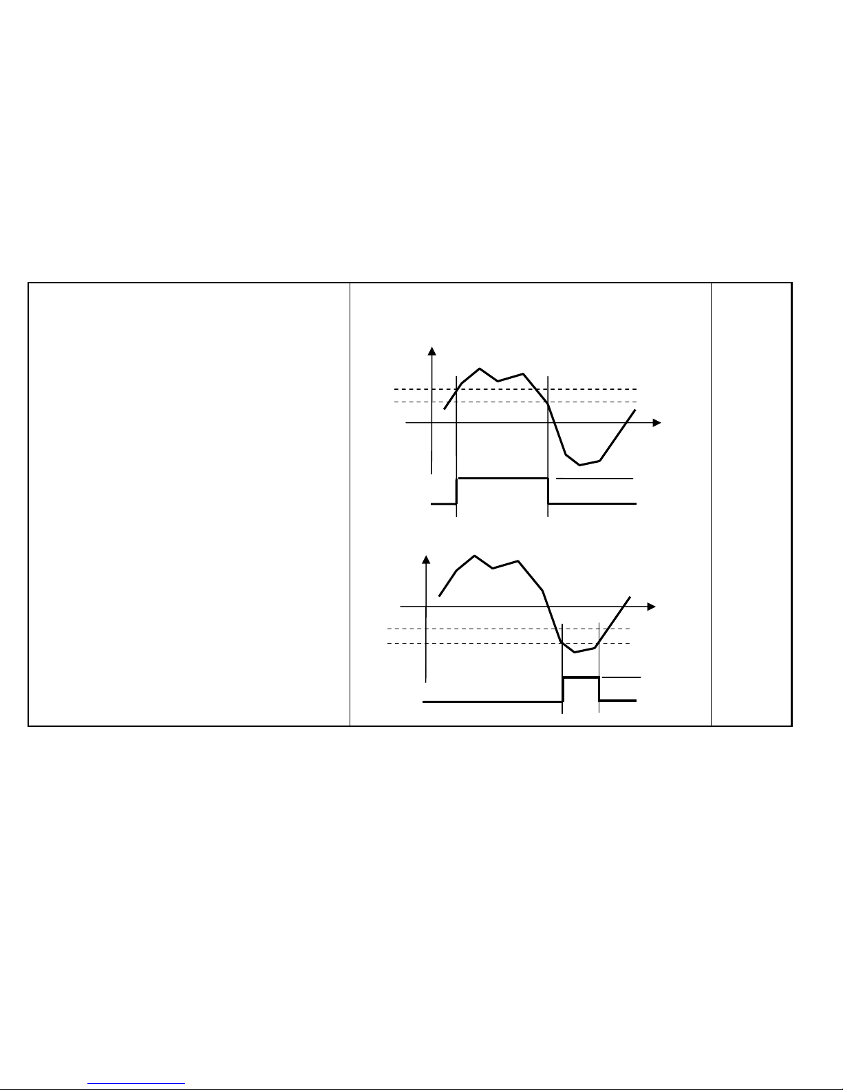
prw2101a0600p_01 76 / 105
PV rate of change
Default: „Invert = OFF”
The MultiCONT counts PV rate of change in every 5 seconds.
When there are more transmitters in the loop and cycle time is
more than 5 seconds, PV_Rate is calculated per cycles.
( t1-t2 5sec )
PV rate of change speed is [ PV/min] =( PV
t1
-PVt2)*60/( t1-t2)
There are two operation m odes, depending on the value of the
parameters:
1.
RP1 > RP2 ≥ 0
For example: Relay becomes energized when level is
increasing in the tank too fast.
2.
RP1 < RP2 ≤ 0
For example: Relay becomes energized when level is
decreasing in the tank too fast.
Inversion of the operation can be performed with selecting
„Invert = ON”
RP1
RP2
PV rate
of change
t
RP1
RP2
Energized
De-Energized
RP1>RP2≥0
t
RP1
RP2
Energized
De-Energized
RP1<RP2≤0
PV rate
of change
Page 77
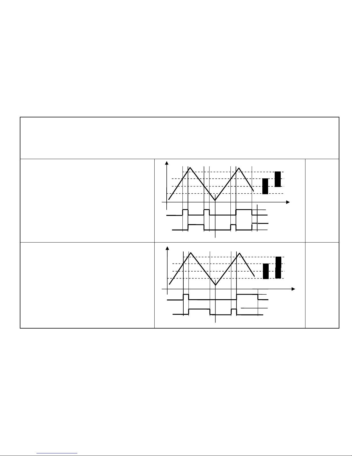
prw2101a0600p_01
77 / 105
Sequential
Default: „Invert = OFF”
More operation modes are possible to use depending on the values of the parameters.
There is only one relay in energized state. When all relays are in de-energized state, then new cycle is started and relays will be reversed.
In the followings, there is an example for the operation in case of two relays ( max. 8 relays can be operating in a group )
Sequential
1. Different switching points for the relays for turning ON
and OFF
Rx-RP1 > Rx-RP2
Emptying with energized relay
RP1
RP2
Sequential
2. Same switching points for turning ON and different
switching points for turning OFF for the relays.
Rx-RP1 > Rx-RP2
Emptying with energized relay
RP1
RP2
LEV
R2 ON RP1
R1 ON RP1
R1 OFF RP2 R2 OFF RP2
ON RP1
RELAY 1
OFF RP2
ON RP1
RELAY 2
OFF RP2
1. cycle 2. cycle
LEV
R2 ON RP1
R1 ON RP1
R2 OFF RP2
R1 OFF RP2
ON RP1
RELAY 1
OFF RP2
ON RP1
RELAY 2
OFF RP2
1. cycle 2. cycle
Page 78
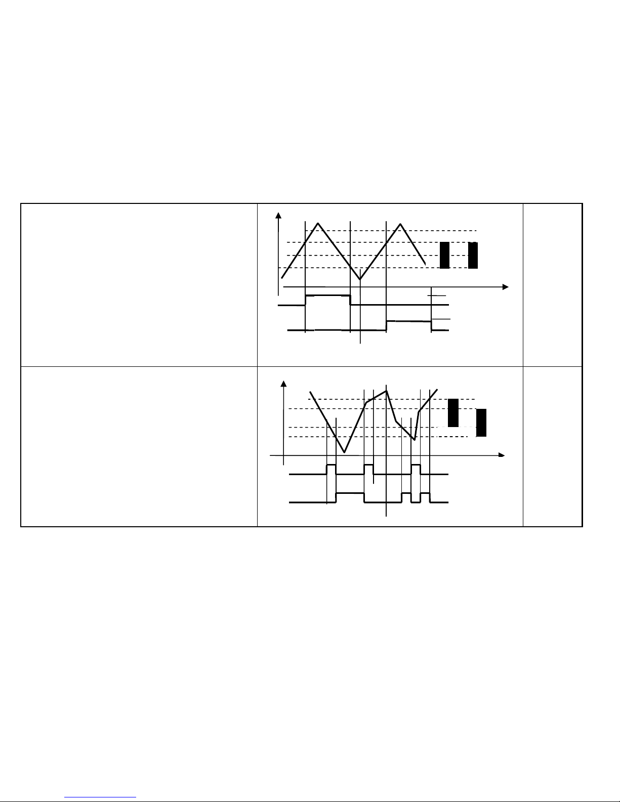
prw2101a0600p_01 78 / 105
Sequential
3.
Same switching points for the relays for turning ON and
OFF
Rx-RP1 > Rx-RP2
Emptying with energized relay
In case of x ( x=2..8 ) relays, relays are operating alternately
RP1
RP2
Sequential
4. Different switching points for the relays for turning ON
and OFF
Rx-RP1 < RX-RP2
Filling with energized relay
RP1
RP2
LEV
1. cycle 2. cycle
ON RP1
RELAY 1
OFF RP2
ON RP1
RELAY 2
OFF RP2
R1 OFF RP2
R2 OFF RP2
R1 ON RP1
R2 ON RP1
LEV
R2 ON RP1
R1 ON RP1 R2 ON RP1
R1 OFF RP2 R2 OFF RP2
ON RP1
RELAY 1
OFF RP2
ON RP1
RELAY 2
OFF RP2
1. cycle 2. cycle
Page 79
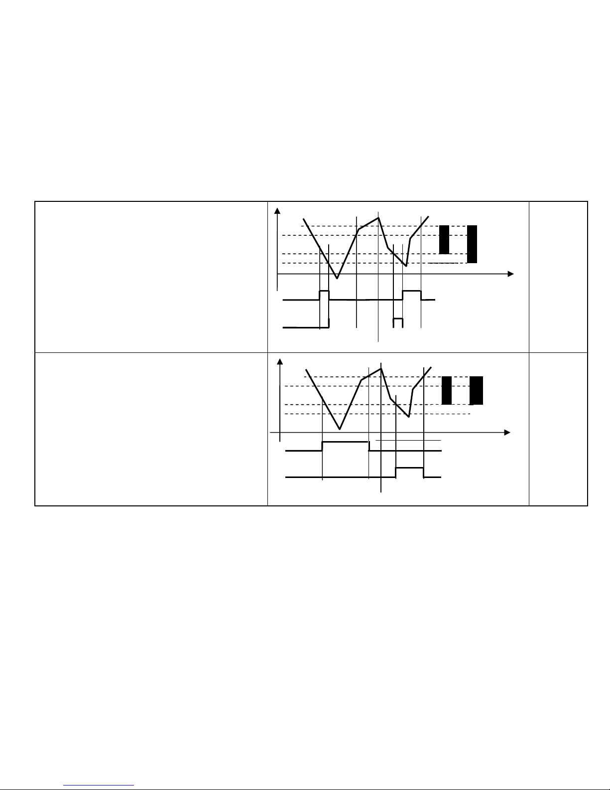
prw2101a0600p_01
79 / 105
Sequential
5. Different switching points for turning ON and same
switching points for turning OFF for the relays
Rx-RP1 < RX-RP2
Filling with energized relay
Sequential
6. Different switching points for turning ON and same
switching points for turning OFF for the relays
Rx-RP1 < RX-RP2
Filling with energized relay
In case of x ( x=2..8 ) relays, relays are operating alternately
RP1
RP2
LEV
1. cycle 2. cycle
ON RP1
RELAY 1
OFF RP2
ON RP1
RELAY 2
OFF RP2
R1 OFF RP2
R2 OFF RP2
R1 ON RP1 R2 ON RP1
R1 ON RP1
LEV
1. cycle 2. cycle
ON RP1
RELAY 1
OFF RP2
ON RP1
RELAY 2
OFF RP2
R1 OFF RP2
R2 OFF RP2
R2 ON RP1
Page 80
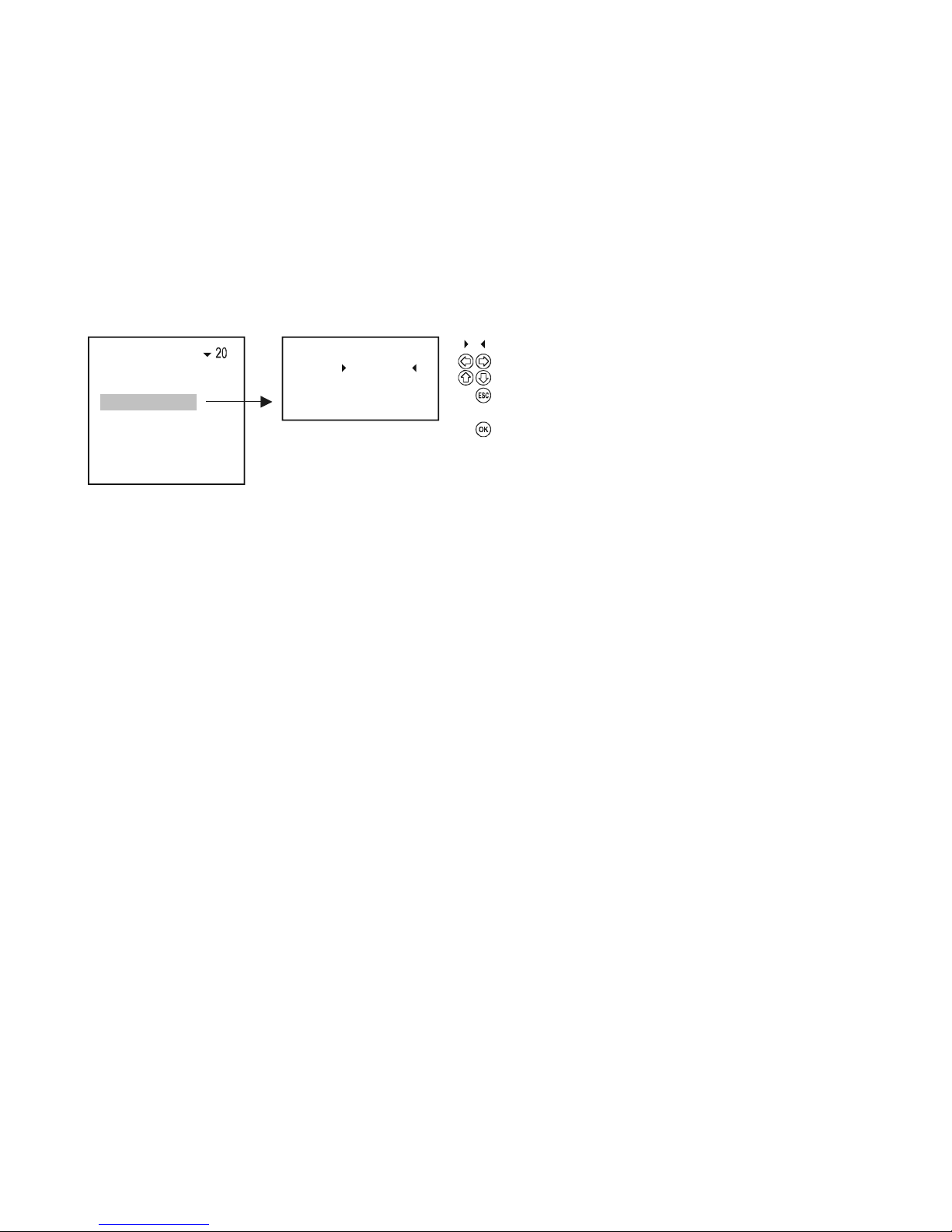
prw2101a0600p_01 80 / 105
5.7.3.3 Configure parameters
RP3 = 0
RP2 = 12.45
Parameter 23
RP1 =
+ 0003.45
Program
Source
Function
Parameter
Invert
Clear TOT
Update TOT
Te s t
Parameter to be edited
Selection of digit position
Modifying sign and number
For RP1 steps back to "Pro
g
ramming" sub-menu,
for RP2 and RP3 steps back to the previous parameter
Accepts parameter change and steps to the next,
pressin
g
for RP3, values of RP1...RP3 are loaded to the
memory and steps back to "Programming" sub-menu
Page 81
prw2101a0600p_01
81 / 105
5.7.3.4 Invert
The operation of the relay can be inverted by switching on the inverter.
Default: Off
Invert 26
On
Off
Not selected
Selected
Select using
Selected choice gets applied immediately
5.7.3.5 Deleting TOT
Quantity (TOT1 and TOT2) summation is done in the flow-measuring transmitters. In the MultiCONT it is possible to transmit the TOT2 in preset units in the form of
relay impulses. In order to do this, the relay has to be switched to ‘Impulse F’ mode. In the ‘RP3’ parameter (belonging to the relay), specify the volume that will
trigger 1 impulse (the length of 1 impulse is about 200 ms). There is a ‘PULSE’ and a ‘TOTAL’ variable for each relay programmed to work in ‘Impulse F’ mode. The
‘TOTAL’ variable of the relay goes after the ‘TOT2’ variable of the transmitter. The volume difference between the 2 variables, given in ‘RP3’ is put into the ‘PULSE’
variable. The value in the ‘PULSE’ variable is transmitted to the output of the relay. The ‘TOTAL’ and ‘PULSE’ relay variables get into the “non-volatile” memory even
in the event of a power failure, as a result of the (automatic) saving done every 6 minutes.The relay impulses that occur in the time elapse between the last save and
the return of power get counted again after the power supply is turned on. In order to avoid repeated counting, use a UPS.
Example: Let the TOT2 value of the transmitter be 1000m
3
. Let the TOTAL value of the relay also be 1000m3. Let the PULSE value of the relay be 0.
At the same time, assume the RP3 parameter of the relay to be 10m
3
. In this case, no impulses appear at the relay output, because the TOT2 value of the transmitter
is the same as the TOTAL value of the relay. Based on the measurement of the transmitter the TOT2 value changes from 1000m3 to 1050m3, the change being 50m3.
Also, based on the RP3 parameter of the relay (10m
3
unit volume), 5 is added to the value of the PULSE variable, with the change being 5*10=50m3. The relay then
counts 5 impulses. After this, the value of the relay’s PULSE becomes 0, while that of TOTAL becomes 1050m
3
Once in this menu, pressing ’OK’ will delete the values of the relay’s ’TOTAL’ and ’PULSE’ variables. This results in the total volume in the transmitter’s ’TOT2’
variable to be counted to the output of the relay based on the unit set in the ’RP3’.
The delete operation is followed by the window below.
Clearing TOT
Press OK
Page 82
prw2101a0600p_01 82 / 105
5.7.3.6 Refreshing TOT
Once in the menu, pressing ’OK’ will copy the transmitter’s ’TOT2’ value into the relay’s ’TOTAL’ variable, and then delete the contents of the relay’s ’PULSE’.
The transmitter and the MultiCONT become synchronised.
The update operation is followed by the window below.
Updating TOT
Press OK
5.7.3.7 Testing
Relay operation can be tested as seen below.
Te st 2 4
On
Off
Toggle
Not selected
Selected
Select us in g
Changing the selection will change
the state of relay immediately
In “toggle” mode, pressing
causes the state of the relay to switch.
Page 83
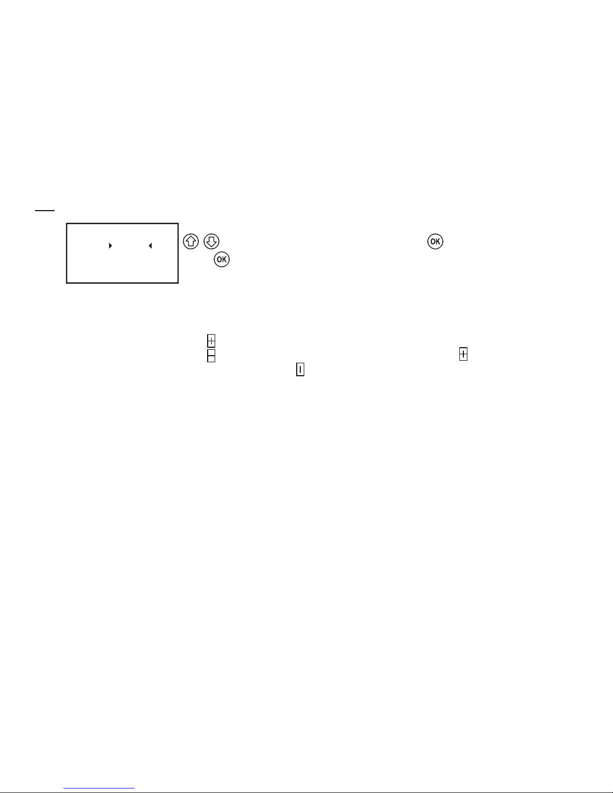
prw2101a0600p_01
83 / 105
Note:
1.
RP3 = 0
RP2 = 12.45
Parame ter 23
RP1 =
0001.25
To program the parameter select the relevant parameter in Main menu/Relays/Relay/Program/Parameter using the
buttons, enter the value in between the pointers and press . Programming can only be completed by
pressing
after setting RP3 (even if it is zero or not applicable in the given function!)
2. Inactive relays are de-energized (See: Main menu/Relays).
3. More than one device can be assigned to any of the relays (Main menu/Relays/Program/Source)
4. The result will be the mathematical combination of the sources.
If the measurement mode or dimensions of devices are different MultiCONT will send error message (See 6. Errors, Error messages)
5. The result of the transmitters marked with are added.
6. The result of the transmitters marked with is subtracted from the sum of the result of the transmitters marked with
7. Computes the average of the results of the transmitters marked with
8. If the Error function is selected no (source) assignment is required since errors of all active devices will be monitored.
9. Relay state will not be changed (HOLD) if its assigned source does not reply!
10. The device will indicate program error if:
There are multiple sources with different dimensions
„Impulse F” function is selected, and there are multiple sources or RP3=0
„Alt S” or Sequential function is selected, and more than 8 relays are assigned to one device or the sources are different
(e.g.: PV for 1 relay, and SV for another)
The sources are SV, TV, and QV but the COM3 command is not selected
ALARM, G function is selected and dimensions of the transmitters’ measurement values are different
For a detailed overview of the Programming see Appendix 3.
Page 84
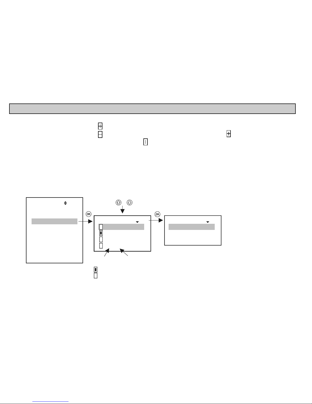
prw2101a0600p_01 84 / 105
5.8. OPERATION AND PARAMETERS OF CURRENT OUTPUTS
First of all a device should be assigned to the current output (Main menu / Current outputs / Program / Source).
The result of the transmitters marked with are added.
The result of the transmitters marked with is subtracted from the sum of the result of the transmitters marked with . (difference measurement)
Computes the average of the results of the transmitters marked with
Secondly the relevant function should be selected and configured in (Main menu/ Current outputs /Program/Function). Finally the parameters have to be
programmed such that the values of the dimensions of CP1 and CP2 be determined by the transmitter(s). Thus if the measurement mode is LEVEL [m]
(e.g. for SE-300 P01=x1 P00=00x), then the programming has to be in LEVEL [m] too (Main menu/ Current outputs /Program/Parameter).
For a detailed overview of the programming steps see Appendix 4.
5.8.1. Selection of Current outputs
It is impossible to enter the current output menu if the system does not contain a single current output. The number of relays in the system can be viewed under Main
menu/MultiCONT config/ Report. (See chapter 5.4.12)
Devices
Current outs.
Inputs
UIM-s
Default config
Relays
MultiCONT config.
Save config.
Load config.
Main menu
05
Select using &
Current outs. 18
01: C1_IN
02: C12MB
:
12: C12n
01: C1_IN 19
Program
Short TAG
Info
List number
of curr. out
Curr. output ID
Short TAG
Active
Not active
(
output current )= 0mA
Page 85
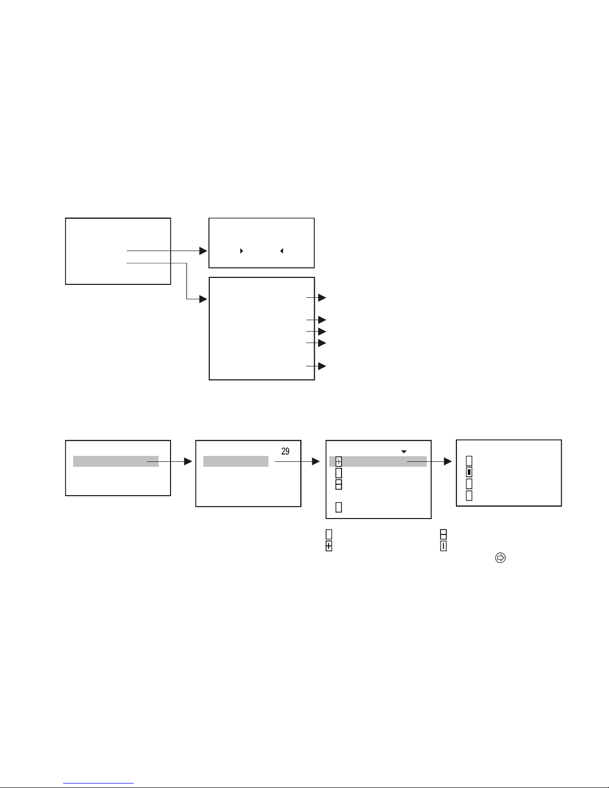
prw2101a0600p_01
85 / 105
5.8.2. Properties of the selected Current Output
01: 1_INC 19
Program
Short TAG
Info
Short TAG
C1_IN
34
Input:
Output:
ID:
Parent:
Location:
0.589
12.45 mA
9728718160
Internal
9729718161
Info
34
The value that the output current was calculated from
(if CP1...CP3 are known)
Actual value of the output current
ID of the current output
For an internal curr.out., this is the MultiCONT's ID,
for an external one, this is the module's ID
Location of the curr. out. (Internal=in MultiCONT,
external=in module)
5.8.3. Current Output programming
5.8.3.1 Source selection
One or more devices can be assigned to a single current output
01: SE300
PV
SV
TV
QV
1901: C1_IN
Program
Short TAG
Info
Program
Source
Function
Parameter
Te s t
10
2
3P8
: SE30
: SC380
: S 3 0
:
n: ST-300-1
Source 30
Not assigned
Assigned with a "+" sign
–
Modify using
A
ssigned with a " " sign
Assigned by averaging
Page 86
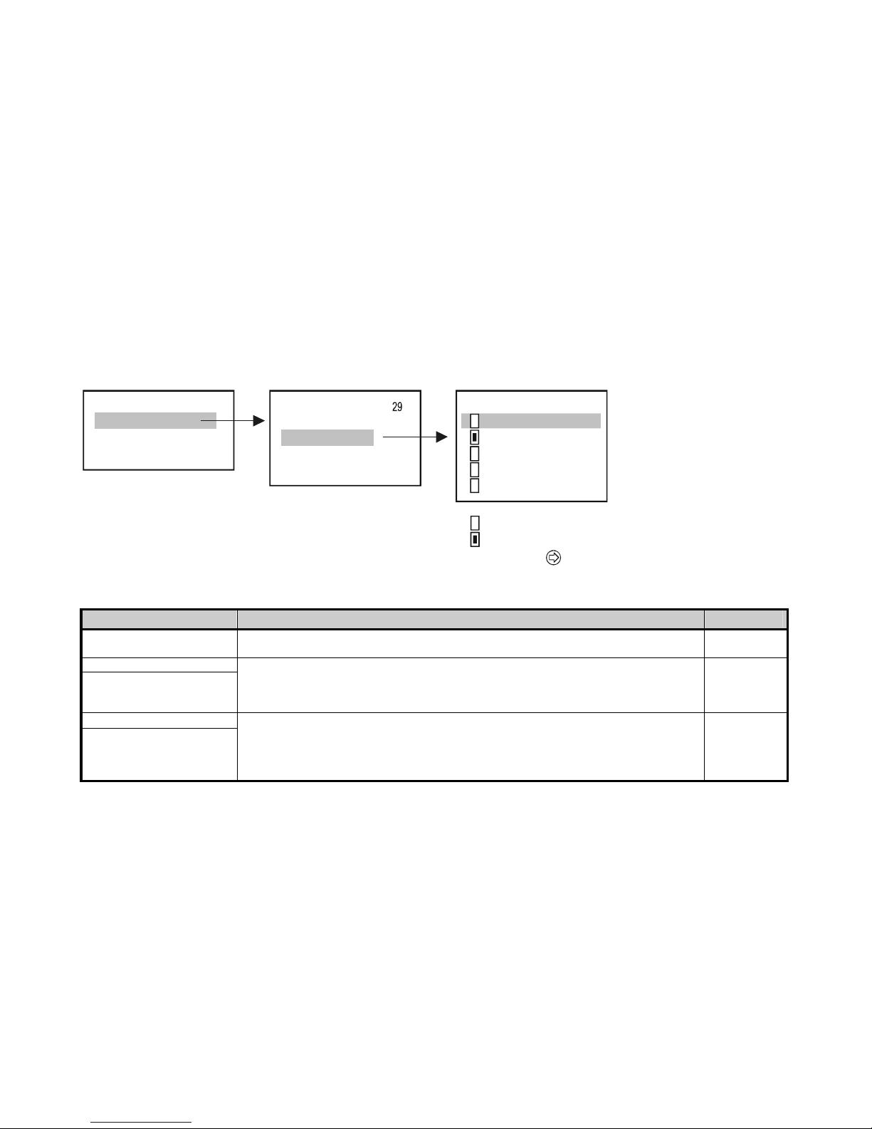
prw2101a0600p_01 86 / 105
In the above example, current output C1_IN is controlled by the difference between the secondary values of SE300 and SP380. In the case of a single unit, the sign is
indifferent; in fact, average might as well be selected. In the case of the selection of multiple devices, functioning depends on the result of the mathematical sum. If in
the case of selected multiple devices the dimensions or the values are different, the unit will display an error message. Upon selecting the value, confirm that the
appropriate HART command has been seleceted for the device (See Main menu/MultiCONT config/HART / command set, see chapter 5.4.5.5)
5.8.3.2 Function
28Curr. out.: C1_IN
Program
Short TAG
Info
Program
Source
Function
Parameter
Te st
Var iab le
Error 3.6 mA
Error 22 mA
Var iable H
Var iable H
= 3.6mA
= 22mA
Function 31
Not selected
Selected
Select using
FUNCTION DESCRIPTION OF OPERATION PROG.PAR.
Variable
Operates in accordance to the selected (PV, SV, TV, QV) value in the “Source” menu point.
The value in CP1 parameter is assigned to 4mA, the value in CP2 parameter is assigned to 20mA.
CP1
CP2
Error 3.6mA
Error 22mA
CP3=0 in every cases it is the error current
CP3=n in case of “n” coded error it is the error current
Error codes (see chapter 6)
If there is no error, value of the current output is 4mA
CP3
Variable H = 3.6mA
Variable H = 22mA
The previous two functions in one:
Until there is no error, it works according to the selected (PV, SV, TV, QV) value in the “Source” menu
point.
The value in CP1 parameter is assigned to 4mA, the value in CP2 parameter is assigned to 20mA.
In case of any error, selected error current will be applied.
CP1
CP2
CP3
Page 87
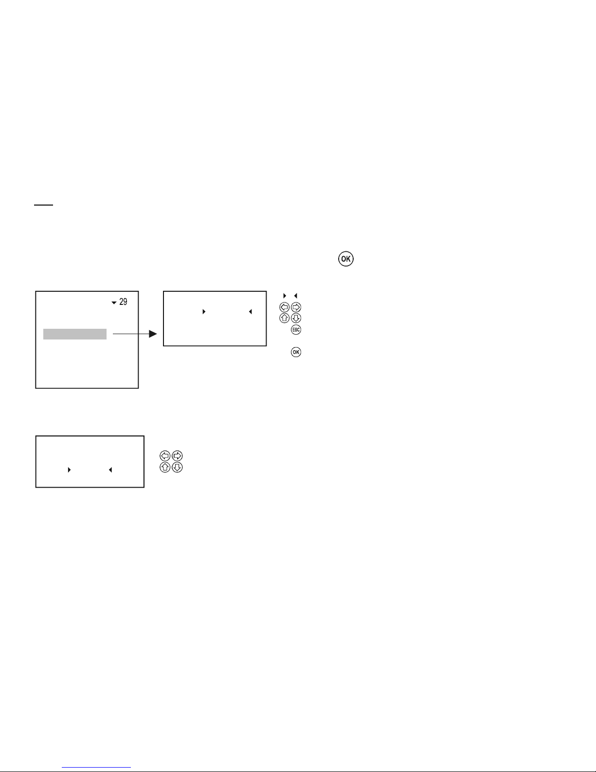
prw2101a0600p_01
87 / 105
Note:
1. The device will display an error if the selected mode is “Variable” and CP1=CP2
2. Value of the output current will not change (HOLD), if the assigned device does not respond or responds with an “Err xx” error!
3. If the current output is not active the output will be 0 mA.
4. If the Error function is selected, then no Source assignment is required since errors of all active devices will be monitored.
5. The modified parameters can only be saved when the cursor is on CP3 by pressing .
5.8.3.3 Parameter configuration
CP3 = 0
CP2 = 12.45
Parameter 32
CP1 =
+ 0003.45
Program
Source
Function
Parameter
Te s t
Parameter to be edited
Selection of digit position
Sign and number modification
from P1: steps back to "Programming" sub-menu,
from P2: and P3 steps back to the previous parameter
Accepts parameter change and steps to the next row.
Pressing when P3 is highlighted, loads the values of P1... P3 into
the memory and steps back to "Programming" sub-menu
C
CC
CCC
5.8.3.4 Testing
The current output can be tested in steps of 1A. Upon changing the numbers, the output changes immediately, and it is not necessary to press OK.
Te s t
12.125
33
Selecting the digit position
Sign and number modification
Page 88
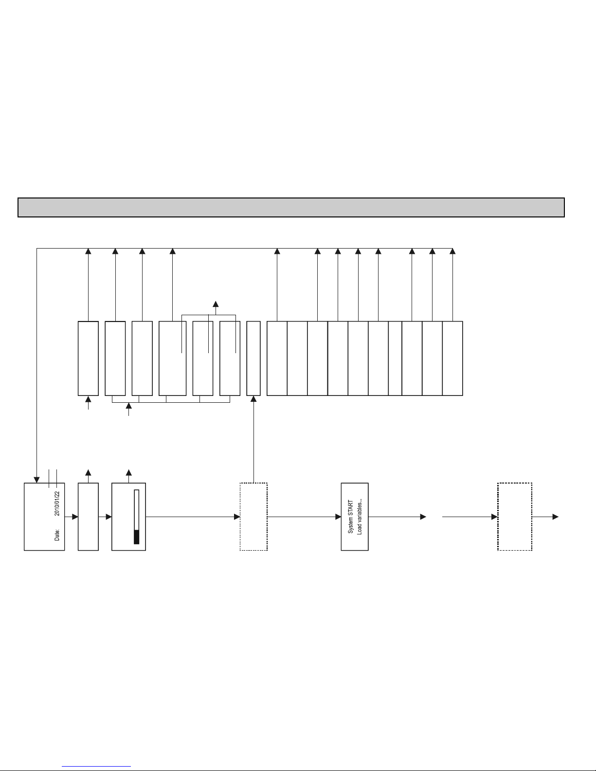
prw2101a0600p_01 88 / 105
5.9. THE BOOT PROCESS
At every powering on, a test program runs testing the MultiCONT hardware. The whole process can be followed on the display in English. The procedure takes
about 40s.
MultiCONT
Version: 01.02.00
Software version Release date of software version
System START CODE FLASH ERROR
RESTARTING !
Restart in case of error
System START
Tes tin g D ATA…
FLASH1 NOT PRESENT
RESTARTING !
FLASH2 NOT PRESENT
RESTARTING !
In case of D ATA FLASH
or page CRC error
DATA FLASH ERROR
RESTARTING !
Number of the
wrong page
IA2 FLA SH ERROR
IA1 FLASH ERROR
VARIABLE ERROR
RESTARTING !
VERSION UPDATE
DEFAULT LOADING
DEVICE ERROR
RESTARTING !
ROUTE ERROR
RESTARTING !
RELAY ERROR
RESTARTING !
CURRENT
ERROR","RESTARTING!
LOGER ERROR
TYPE ERROR
RESTARTING !
U485 NOT PRESENT
RESTARTING !
M485 NOT PRESENT
RESTARTING !
Checking cloc k
in the background
In case of clock error
relative time is shown
on the display
Restarting
No error
Tes tin g C ODE
RTC NOT PRESENT
Page: 1234
Page: 1234
Page: 1234
In background:
In case of P_D type
devices LOGGER
unit is checked
Page 89
prw2101a0600p_01
89 / 105
1: SE300 1 M
---
Still no valid data
3.125m
LOGGER NOT PRESENT
LOGGER PRESENT
Hardware check is successful.
MultiCONT is in measurement mode
and queries the active transmitter
2010.01.21 A 09.32
1: SE300 DIST 1 M
2010.01.21 A 09.32
On the display, the result of the first number
list-tagged transmitt er can be seen.
-
Query of the 2
nd
transmitter is in progress.
(see: 5.10. Measurement Mode)
Page 90
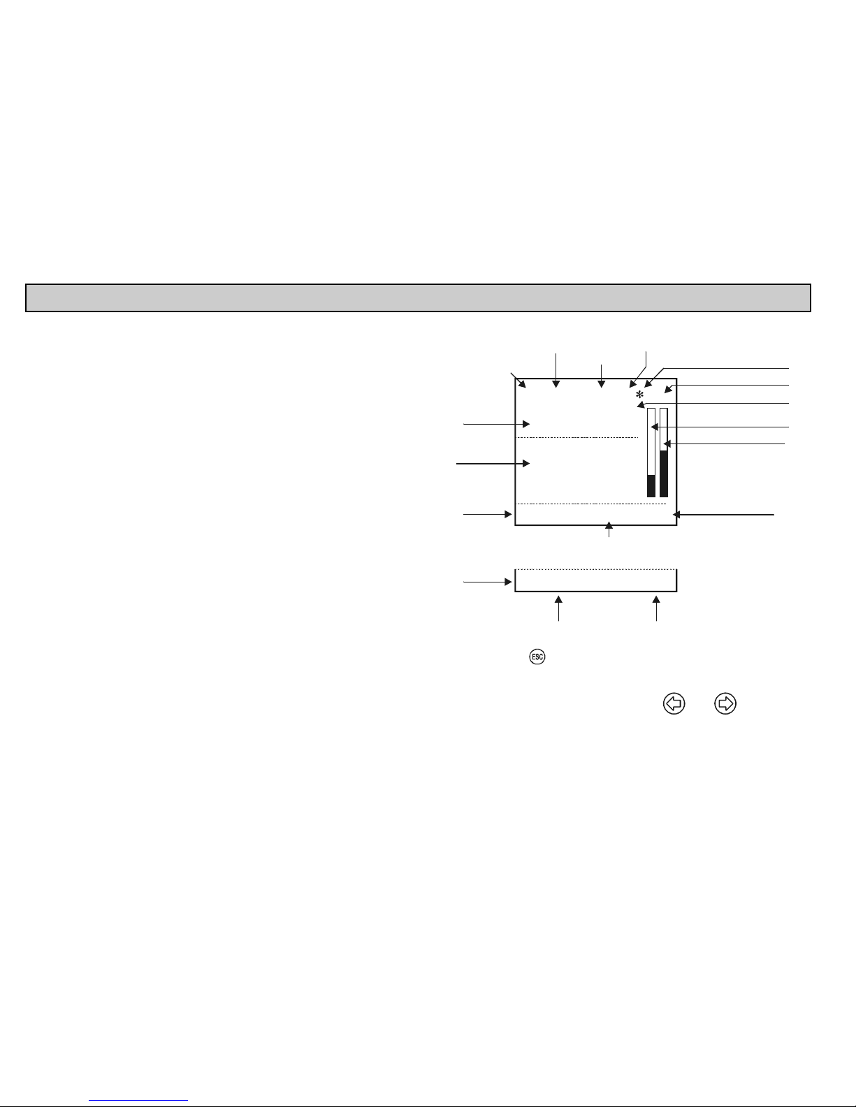
prw2101a0600p_01 90 / 105
5.10. MEASUREMENT MODES
After the boot test the MultiCONT will automatically enter the Measurement Mode /
standard display image. Measurement values will be queried and displayed in
accordance with the contents of the device list read from the memory and the
settings in Main menu / MultiCONT config. / Main display / Step. Maximum 5 data
per device can be displayed simultaneously on the display
(1 main display – see 5.4.3 - and 4 on the list display – see 5.4.4) together with
dimensions and abbreviations (DIST, LEV, VOL, FLOW, PV, SV, TV, QV, TOT1,
TOT2, E). In the upper row the device identifier (Short TAG), List Tag (1,…9,A.,...F)
can be seen and the device communicating actually with the MultiCONT.
When the device communicates via RS485, the „*” flashes. There are two bargraphs
on the display. One is the „sensor range” (only for NIVELCO transmitters), this
indicates the transmitter’s measurement range (the tank level between the maximum
and minimum measuring distance). The other is the „output range” that indicates the
4-20mA range of the transmitter.
n: S 300E-11 MFLOW
A 06:41
2006.04.11
5486. m
Bargraph/sensor range
Bargraph/output range
Variable (PV, SV, TV, QV)
menu display ID
op. mode
device ID
(short TAG)
n=number
of the
in the list
1...9, A...F
device
Code of the device error
or "Locked" message if
program protecting switch is on
No. of error logs
Acknowledge, (erase)
with
RS 485 communication
SV: 0.852 m
LEV: 0,514 m
TOT1: 1542 m3
TOT2: 1.25 E7 m3
Main
display
List display
Status
field
A
ctual date and time
Err11Errors: 4
PV
l/s
(no errors)
(max 4 rows)
A
= absolute time
R = relative time
2
number of queried device
(flashes)
Status
field
(on error)
In this mode, it is possible to view the „Bargraph display”, the „User display” (Range, Double, Difference, Average see Main menu / MultiCONT config / User
display - chapter 5.4) selected by the user, the relay-device and current output-device assignments, and also the error list, using and for selection.
See Appendix 5
After the termination of a possible error, the display keeps on displaying the error until the error is acknowledged by pressing the ESC button. The query of the
devices, the control of the relays and the current outputs and the servicing of the RS485 all happen continuously during programming. The MultiCONT automatically
returns to measurement mode 5 minutes after the last button was pressed. It also records and saves the number of switchings and worktime of the relays every
6 minutes. The 6 minutes commence after the automatic exit.
Page 91
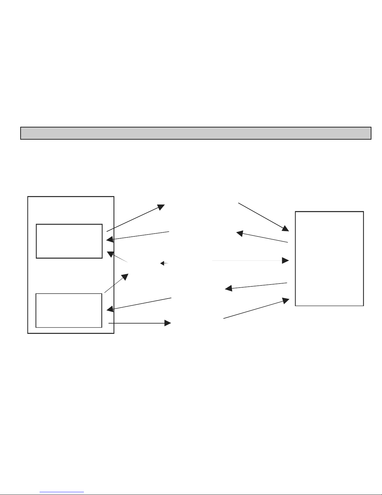
prw2101a0600p_01
91 / 105
5.11. SAVING, LOADING THE CONFIGURATION OF THE MultiCONT
Settings of the MultiCONT are stored in a non-volatile FLASH memory (FMA). The content of this FLASH memory is replaced into the operative memory (OM) (which
is a volatile memory) when MultiCONT is turned ON or restarted. Settings are saved automatically when exiting from the Menu.
In addition to this, working hours and the switching number of the relays are saved in every 6 minutes into the FLASH memory. In the “Main menu”/”Save config.”
menu point a safety copy (FMS) can be made from the automatically saved settings.
Load of the safety copy can be performed in the “Main menu”/”Load config.” menu point. When turning ON or restarting, memory content is replaced into the
operative memory from the FLASH memory, if it is faultless (calculated and stored CRC are the same). If there is a safety copy from the settings, the content of this
(FMS) is copied to the operative memory (OM) and the automatic saving storage (FMA) FLASH memory, when ESC and buttons are pressed simultaneously.
FLASH
Nem felejt memória
Beolvasás:bekapcsolás/
újraindítás, ha nincs hiba
FMA
Automatikus
mentés
FMS
Biztons gi /
beállítás mentés
á
RAM ( OM )
Operatív memória
A készülék
kikapcsolásakor a
tartalma elvész
Bekapcsolás/újraindításkor
az ESC és egyidej
megnyomása
Automatikus mentés,
menüb l kilépéskor
Beállítás mentés
menüb l
Beállítás feltöltés
menüb l
Page 92
prw2101a0600p_01 92 / 105
6. ERROR CODES
In the event of an error, the message “errors” (see Measurement mode, appendix 5) immediately appears
regardless of which device the error is connected to.
Errors occurring during operation will be collected in the E (Error) table where the error identifier message can
be viewed.
Errors
E
01: SE300-11 : Response
02: ST300-11 : Program
03: SP300-11 : Device
“Sensor” and “Reply” error message will automatically be erased from the list upon termination of the error.
Other errors entries will remain in the table until acknowledgement by pressing ESC. Thus for instance if a relay or current output set for function “Error”, it will
indicate the error even after termination of the error until the error is acknowledged as above.
ERROR CODE MESSAGE ERROR DESCRIPTION CORRECTION
1 Init Device does not reply after switching-on* Check wiring of device
2 Reply Device with normal operation does not respond ** Check wiring of device
3 Sensor Sensor failure on the device *** Check device (transmitter)
4 Device Other device Error (See chart next page)
Check programming of device ( See relevant Install and Prog. Manual), and
measurement conditions
5 Program
Error occurred during programming of relay or current
output ****
Check programming
6 Save Error occurred in the course of saving to memory If this happens repeatedly, send device to the manufacturer.
7 Log
Logging does not answer or a failure may happened
during the saving process
Please check the memory card, if necessary try with another SD card.
* An active device on the list does not reply after switching-on. Possible reasons:
the system was modified before turning on (device was disconnected, the wiring was changed, etc.)
device failed to reach operation conditions during the boot process (and is not yet able to measure) thus this error message appears
(e.g. in solid applications, STD-300 transmitters may not respond until the amplification reaches operation conditions).
** A device that had been working perfectly suddenly stops responding. Possible reasons:
the device has gone wrong
broken cable
noisy HART line (See Main menu/MultiCONT config/HART test)
Page 93

prw2101a0600p_01
93 / 105
*** A special error message belongs to sensor failures. This error can appear in
the case of ultrasonic transmitters due to the breakdown of the transducer or
during a dusty filling process, when if there is a display, a NoEcho message is
displayed. In case of magnetostrictive transmitters, this error can be due to the
cracking of the magnet disc, or a break in the magnetostrictive wire.
1: SE300-12 M DIST
2 Errors: 1
SENSERR
Err00
Device responds but there is no
valid result because of sensor
error.
**** Programming error will be caused if:
assignment of more than one source with different dimensions to a relay or current output
an appropriate value (PV, SV, etc) is assigned to a current output and CP1=CP2 (see 5.8 Operation and parameters of current outputs)
assignment of flow value (Impulse F) to a relay and there is more than one source (see 5.7 Relay configuration)
assignment of flow value (Impulse F) to a relay and RP3=0 (see 5.7 Relay configuration)
more than 8 relays with „Alt S” or Sequential function are assigned to a transmitter
different variables are selected in the case of a relay with „Alt R” function
the source is SV, TV or QV, but the COM3 HART command is not selected
ALARM, G function is selected, but the dimensions of the measured values are not the same
Page 94
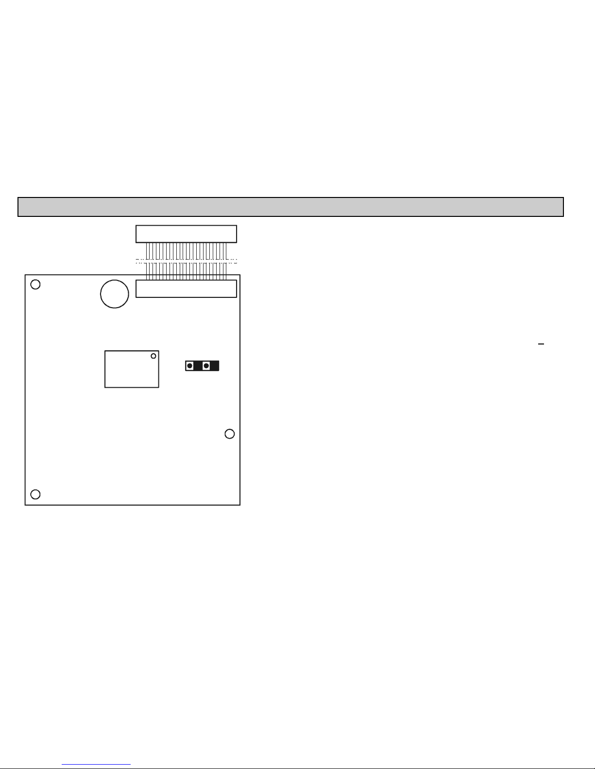
prw2101a0600p_01 94 / 105
7. HARDWARE PROTECTION OF THE SETTINGS
ON OFF
IC2
S1
C26
For access, loosen the nuts fastening the front panel.
The program protection switch in ON position will prevent modification of parameters
affecting operation such as:
relay parameters
current output parameters
activation of devices
remote programming
denying access to the Service menu
denying permission to run DEV detect, EXT detect under MultiCONT config
The switch does not prevent modifications that do not influence the operation of
the
MultiCONT (such as language, backlight, user image, sorting, restart, etc)
Page 95
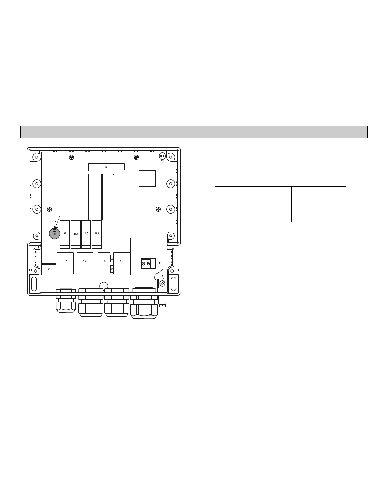
prw2101a0600p_01
95 / 105
8. FUSE REPLACEMENT
PRW10A02-A
RS485
+
B1 fuse
In order to change the fuse loosen four nuts fastening the front panel, carefully tilt
the front panel forward, such that the cable band is not under tension and replace
the fuse.
Warning! Only use fuses specified in the table below:
The device contains 1 network fuse. Its value depends on the
power supply.
POWER SUPPLY FUSE B1
85…255 V AC 50…60Hz T400mA
11.4…28 V AC 50…60Hz
11.4…40 V DC
T1A
Page 96

prw2101a0600p_01 96 / 105
9. SERVICING
9.1. BOX MESSAGES:
No. Box Message Explanation
1 No CODE! Secret code is not set
2 In manual prg! The transmitter is under manual programming
4 Already unlocked! No code in the trasnmitter ( i.e. 00000000 )
5 Unlock, please! Secret code needed for modification (see.”Main menu/”MultiCONT config.”/”password”)
6 HART error! Communication error
7 TOT1 cleared! Value of TOT1 deleted
8 TOT2 cleared! Value of TOT2 deleted
9 HART no reply During programming the device does not respond, or bad data
10* HART comm. error Error in HART message (parity, framing, overflow, …)
11* HART logical error Other logical error in HART message
12* HART write protect The parameter cannot be written
13 Unknown dev/comm The address (Long address) in the HART message is not found in the list
14 Parameter saved Successful save of the parameter
15 Save error Error in writing to FLASH memory
16 Device added The selected device in the „Device detect” menu has been included into the list.
18 Unknown param. Unknown parameter during device detection
19 Default loaded Loading of Factory default ( depending on type ) was successful.
20 PSW cleared Secret code is deleted
23 FLASH error FLASH error at boot
24 Same address! Multiple same Long address found during DEV detect
25 No HART device In the „Device detect” menu, searched for devices with „Short addr.” between 0..15 but did not find any
26 Load error Error when reading from FLASH memory
28 No comp. Device Device is not NIVELCO compatible
30 HART:Parse error The received data are not applicable
31 HART:Invalid sel. The received HART command is unknown to the MultiCONT
Page 97

prw2101a0600p_01
97 / 105
No. Box Message Explanation
32 HART:Too large The received HART command is longer than standard
33 HART:Too small The received HART command is shorter than standard
34 HART:Few data
35 HART:Device spec. Bad parameter sent during remote programming
36 HART:Access restr.
37 HART:Busy
38 HART:Comm. not. imp. The received HART command is unknown to the MultiCONT
39 Please wait! DEV detect cannot run due to periodic disturbance on the HART line, which causes continuous error!
40 TOT cleared TOT deleted during relay progamming ( Impulse F )
41 TOT updated TOT updated during relay progamming ( Impulse F )
42 No in RP mode Device could not enter „Remote programming” (RP) mode during programming
43 Stick in RP mode Unsuccessful exit after remote programming of device
9.2. OTHER MESSAGES:
No. Message Explanation
1 Scanning HART line Displayed during device detection
2 Logical error
- Displayed instead of user’s image, if difference or average is selected, but there is only one active device
- Displayed if the dimensions of the results of the selected devices are different
3 No user screen In „Main menu”/”MultiCONT config.”/”User display” „None” is selected
4 No active device Displayed during measurement or instead of user’s image, when there is no avtive device
5 No HART device The unit’s device list is empty ( run „DEV detect”
6 Locked The hardware switch is on ( the program cannot be modified)
7 No current output Displayed in the position of the „current output assignment” image, if there is no current output in the system
8 No relay output Displayed in the position of the „Relay assignment” image, if there is no relay in the system
Page 98

prw2101a0600p_01 98 / 105
9.3. TROUBLESHOOTING
9.3.1. It is impossible to enter the „Main menu”/”Relays” or „Main menu”/„Current outputs” menu:
There is no relay or current output in the unit. Check the number of relays and/or current outputs in „Main menu”/”MultiCONT config.”/”report” menu.
9.3.2. It is impossible to enter the „Main menu”/”Devices” menu:
The device list is empty. (there are neither inactive, nor active devices in the system, in measurement mode a „No HART Device” message appears on the display.)
9.3.3. A „Please wait” message appears upon selecting „DEV detect”
The HART line is so noisy, that there is no communication, and every command is bad. The only way to exit this state is by switching the unit off and on again.
Check the shielding of the cable and the cable route.
9.3.4. The result of „DEV detect” is the „No device” message
The MultiCONT did not detect any device that responded.
Check for short-circuits or open-circuits.
There is a short-circuit if there is voltage between L+ and SH, but between L+ and L- the voltage is 0V.
The line is open-circuited (cut) if there is no voltage between L- és SH, because there is no voltage drop on the sensing resistor ( R
fi
=255 ) connected
between these 2 points, whereas the loop current should never be 0mA.
Check the terminal voltage at the devices (transmitters). If the terminal voltage is small, it might be due to bad wiring (big intermediate resistance) or big
loop current, resulting on a big voltage drop on the sensing resistor. Connect the devices in to the loop one by one, checking the „Short address” and the
constant current parameter (see: chapter on preparation of transmitters)
Confirm that the device is HART capable (Type, nameplate)
9.3.5. The unit does not start up when switched on
It restarts repeatedly (see: chapter 5.9.)
This can be due to faulty FLASH ( the non-volatile memory in the unit )
Or a bad RS485 card ( types P__-1_A and P__-1_B ), because this is tested at boot, and does not continue in case of an error. Request help from our
Export Sales department.
9.3.6. The „Response” error entry is too frequent
The line is noisy, check the grounding of the cable shielding. If the cable is not shielded, replace it with a shielded cable.
DEVICES
L+ L- SH
Page 99
prw2101a0600p_01
99 / 105
9.4. ADDITIONAL INFORMATION
9.4.1. Problems that may occur during remote programming:
In the case of integer type parameters, MultiCONT
displays all the four digits even if the case of a given
transmitter only one digit is meaningful. For
example:
PRW:
P12 Error state
14
0002
SE-300:
P12: 2
SE-300 only tests the value of digit „a” value( see Manual), and does not display an error if 1002 is written. It even stores this value. It does not indicate any
operational error, but upon reading this parameter from SE-300 1002 is received which does not have any meaning according to the manual!!!!
9.4.2. MultiCONT transmits the parameters without examining them, and the testing is done by the device.
In the event of an error, if the device does not accept it, then a “HART logical error” box message appears on the display.
9.4.3. Use of Second HART Master ( Hand-Held or HART modem + Eview configuration software)
Normally, there can only be one master in HART systems. Since the MultiCONT is a master, other masters can only be used if if the status of every device is set to
inactive, i.e. the MultiCONT is in listen mode. (see „Main menu”/”Devices”) After this, the other master can be connected to the L- and SH terminals (with a 255 Ohm
sensing resistor inside)
9.4.4. Upon exiting remote programming, the unit tests to see if the transmitter really exited the remote programming mode
(During remote programming „RP” appears on the display of the transmitter). If this is not successful, then the „Stuck in RP mode” box message keeps us informed.
In this case, it is not possible to manually enter programming mode!!
9.4.5. When a transmitter does not respond, then „Response” error is entered into the table, but upon termination of the error
(the device responds), this entry is automatically cleared from the table (and does not need to be acknowledged)
This is also true for „Sensor” error ( noEcho, etc ). The states of the relays and current outputs are not refreshed during this process!!!
9.4.6. Upon exiting the menu, MultiCONT immediately saves the modifications
However, there are events that need to be saved, and this happens every 6 minutes. These include:
Work time and number of state changes of relays
The number of times the MultiCONT was turned on (see: „Main menu”/”MultiCONT config.”/”Report”/”Power count”)
The relevant internal variables, if the function of any relay is „Impulse F”, i.e. RP3 sends a unit pulse to the output, (TOTAL and PULSE, see: „Main
menu”/”Relays”/”Programming”/”deleting TOT”)
9.4.7. The error list is cleared when the device is put off
Page 100

prw2101a0600p_01 100 / 105
APPENDIX 1. MANUFACTURER IDENTIFICATION CODES OF HART-CAPABLE DEVICES:
112 "US ELECTRIC MOTORS",
113 "Apparatebau Hundsbach",
114 "Dynisco",
115 "Spriano",
116 "Direct Measurement",
117 "Klay Instruments",
118 "Action Instruments",
119 "MMG Automatiky DTR",
120 "Buerkert Fluid Control
Systems",
121 "AALIANT Process Mgt",
122 "POUNDS INSTRUMENT",
123 "ZAP S.A. Ostrow Wielkopolski",
124 "GLI",
125 "Fisher-Rosemount Performance
Technologies",
126 "Paper Machine Components",
127 "LABOM",
128 "Danfoss",
129 "Turbo",
130 "TOKYO KEISO",
131 "SMC",
132 "Status Instruments",
133 "Huakong",
134 "Duon Systems",
135 "Vortek Instruments, LLC",
136 "AG Crosby",
137 "Action Instruments",
138 "Keystone Controls",
139 "Thermo Electric Co.",
140 "ISE-Magtech",
141 "Rueger",
142 "Mettler Toledo",
143 "Det-Tronics",
144 "TN Technologies",
145 "DeZURIK",
146 "Phase Dynamics",
147 "WELLTECH SHANGHAI",
148 "ENRAF",
149 "4tech ASA",
150 "Brand Instruments",
151 "NIVELCO",
152 "Camille Bauer",
153 "Metran",
154 "Milton Roy Co.",
155 "PMV",
156 "Turck",
157 "Panametrics",
158 "Stahl",
159 "Analytical Technology Inc.",
160 "Fieldbus International",
161 "BERTHOLD",
162 "InterCorr",
163 "China BRICONTE Co Ltd",
164 "Electron Machine",
165 "Sierra Instruments",
166 "Fluid Components Intl",
1 "Acromag",
2 "Allen Bradley",
3 "Ametek",
4 "Analog Devices",
5 "Elsag Bailey",
6 "Beckman",
7 "Bell Microsensor",
8 "Bourns",
9 "Bristol Babcock",
10 "Brooks Instrument",
11 "Chessel",
12 "Combustion Engineering",
13 "Daniel Industries",
14 "Delta",
15 "Dieterich Standard",
16 "Dohrmann",
17 "Endress & Hauser",
18 "Elsag Bailey",
19 "Fisher Controls",
20 "Foxboro",
21 "Fuji",
22 "ABB Automation",
23 "Honeywell",
24 "ITT Barton",
25 "Kay Ray/Sensall",
26 "ABB Automation",
27 "Leeds & Northrup",
28 "Leslie",
29 "M-System Co.",
30 "Measurex",
31 "Micro Motion",
32 "Moore Industries",
33 "Moore Products",
34 "Ohkura Electric",
35 "Paine",
36 "Rochester Instrument
Systems",
37 "Ronan",
38 "Rosemount",
39 "Peek Measurement",
40 "Schlumberger",
41 "Sensall",
42 "Siemens",
43 "Weed",
44 "Toshiba",
45 "Transmation",
46 "Rosemount Analytic",
47 "Metso Automation",
48 "Flowserve",
49 "Varec",
50 "Viatran",
51 "Delta/Weed",
52 "Westinghouse",
53 "Xomox",
54 "Yamatake",
55 "Yokogawa",
56 "Nuovo Pignone"
57 "Promac",
58 "Exac Corporation",
59 "Meggitt Mobrey",
60 "Arcom Control System",
61 "Princo",
62 "Smar",
63 "Foxboro Eckardt",
64 "Measurement Technology",
65 "Applied System
Technologies",
66 "Samson",
67 "Sparling Instrumnets",
68 "Fireye",
69 "Krohne",
70 "Betz",
71 "Druck",
72 "SOR",
73 "Elcon Instruments",
74 "EMCO",
75 "Termiflex Corporation",
76 "VAF Instruments",
77 "Westlock Controls",
78 "Dexelbrook",
79 "Saab Tank Control",
80 "K-TEK",
81 "Flowdata",
82 "Draeger",
83 "Raytek",
84 "Siemens Milltronics PI",
85 "BTG",
86 "Magnetrol",
87 "Metso Automation",
88 "Milltronics",
89 "HELIOS",
90 "Anderson Instrument
Company",
91 "INOR",
92 "ROBERTSHAW",
93 "PEPPERL+FUCHS",
94 "ACCUTECH",
95 "Flow Measurement",
96 "KAMSTRUP",
97 "Knick",
98 "VEGA",
99 "MTS Systems Corp.",
100 "Oval",
101 "Masoneilan-Dresser",
102 "BESTA",
103 "Ohmart",
104 "Harold Beck and Sons",
105 "Rittmeyer Instrumentation",
106 "Rossel Messtechnik",
107 "WIKA",
108 "Bopp & Reuther Heinrichs",
109 "PR Electronics",
110 "Jordan Controls",
111 "Valcom s.r.l.",
prw2101a0600p_01.doc
2010. december 11.
NIVELCO reserves the right to change
technical specification without notice!
 Loading...