


PROGRAMMING MANUAL
For SCA-3!!-4 models with HART
1st edition
Manufacturer:
NIVELCO Process Control Co.
H-1043 Budapest, Dugonics u. 11.
Tel.: (36-1)-369-7575 Fax: (36-1)-369-8585
E-mail:sales@nivelco.hu http://www.nivelco.hu

Basic conception and elements of the ultrasonic measurement
LEV= level (calculated: H-DIST)
VOL= volume (calculated from LEV)
DIST=distance measured
M
a
x
i
m
u
m
m
e
a
s
u
r
i
n
g
d
i
s
t
a
n
c
e
o
f
m
t
h
e
u
n
i
t
(
X
)
M
F
a
c
t
o
r
y
d
e
f
a
u
l
t
P
0
4
=
X
M
M
a
x
i
m
u
m
o
f
t
h
e
u
n
i
t
r
a
n
g
e
F
a
c
t
o
r
y
d
e
f
a
u
l
t
P
0
5
=
X
B
C
l
o
s
e
e
n
d
b
l
o
c
k
i
n
g
(
X
)
B
M
a
x
.
m
e
a
s
u
r
i
n
g
d
i
s
t
a
n
c
e
o
f
t
h
e
a
p
p
l
i
c
a
t
i
o
n
(
H
)
P
r
o
g
r
a
m
m
i
n
g
:
P
0
4
=
H
P
r
o
g
r
a
m
m
e
d
r
a
n
g
e
o
f
t
h
e
a
p
p
l
i
c
a
t
i
o
n
D
i
s
p
l
a
y
e
d
r
a
n
g
e
F
a
c
t
o
r
y
d
e
f
a
u
l
t
:
P
0
6
=
0
F
a
r
e
n
d
b
l
o
c
k
i
n
g
M
i
n
.
m
e
a
s
u
r
i
n
g
d
i
s
t
a
n
c
e
(
X
)
m
P
r
o
g
r
a
m
m
i
n
g
:
P
0
5
=
>
X
X
B
m

CONTENTS
1. PARAMETERS – DESCRIPTIONS AND PROGRAMMING..........................................................................................................2
1.1 Measurement Configuration .........................................................................................................................................................................2
1.2 Current Output ..............................................................................................................................................................................................8
1.3 Relay Output.................................................................................................................................................................................................9
1.4 Measurement Optimisation.........................................................................................................................................................................10
1.5 Volume Calculation.....................................................................................................................................................................................15
1.6 Volume Flow Measuring .............................................................................................................................................................................16
1.7 32-Point Linearisation Curve ......................................................................................................................................................................21
1.8 Service Parameters ....................................................................................................................................................................................21
1.9 Additional Parameters of Flow Metering.....................................................................................................................................................22
2. ERROR CODES ...........................................................................................................................................................................23
3. TABLE OF PARAMETERS
4. SOUND VELOCITIES IN DIFFERENT GASES ...........................................................................................................................26

2 EasyTREK Compact Ultrasonic Level Transmitters
Thank you for choosing a NIVELCO instrument.
We are sure that you will be satisfied throughout its use.
1. PARAMETERS – DESCRIPTIONS AND PROGRAMMING
1.1 Measurement Configuration
P00: - cba Application/Engineering Units
Programming of this parameter will result in loading the factory default with the corresponding
engineering units.
a Operating (measurement) mode
0 Liquid level measurement
b Engineering units (according to “c”)
Metric
ft
0 minch
1 cm inch
c Calculation system
0 Metric
1 US
FACTORY DEFAULT: 000

EasyTREK Compact Ultrasonic Level Transmitters 3
P01: - - ba Measurement Mode
Displayed value on the PC, current output and the switching points of the relays will be interpreted in the engineering units of the (measured or
calculated) process value corresponding to the programmed measurement mode. On the other hand the higher the “a” of the programmed
parameter value the more (measured or calculated) process values can be displayed on the PC by the EVIEW software. (e.g. if P01=b0 only the
Distance, if P01=b5 the Distance the Level, the Volume and the Flow can be displayed. Exception if P01=b2 or b4.)
a Measurement Mode Display symbol
0 Distance DIST
1 Level LEV
2 Level in percentage LEV%
3 Volume VOL
4 Volume in percentage VOL%
5 Flow FLOW
FACTORY DEFAULT: 11
P02: - cba Calculation units
a Temperature
0 °C
1 °F
This table is interpreted according to P00(c), P01(a) and P02(c) and is irrelevant in case of percentage measurement ( P01(a)= 2 or 4 )
b Volume Weight (set also P32) Volume flow
Metric US Metric US Metric US
0 m
3
ft
3
- lb (pound) m3/time ft3/time
1 liter gallons tons tons liter/time gallons/time
c Time
0 Sec
1 Min
2 Hour
3 Day FACTORY DEFAULT: 000

4 EasyTREK Compact Ultrasonic Level Transmitters
P03: - - - a Values Displayed-Rounding
It is important to keep in mind that the instrument is measuring distance as basic quantity.
Measured distance Resolution
X
min
– 2m
1mm
2m – 5m 2mm
5m – 10m 5mm
The resolution depending on the distance can be considered as
a kind of rounding that will be contained in all further value (of
level, volume or volume flow) calculated. Therefore if
programmed for DIST or LEV measurement the setting of P03
is irrelevant.
Displayed VOL or FLOW
Displayed value Displayed form
0.000 – 9.999 x.xxx
10.000 – 99.999 xx.xx
100.000 – 999.999 xxxx.
1000.000 – 9999.999 xxxxx.
100000.000 – 99999.999 xxxxxx.
1 million – 9.99999*10
9
x.xxxx : e
(exponential form)
over 1*10
10
(overflow) Err4
Obviously the decimal position will be shifted with increasing
value displayed. (See table at the left).
Values over one million will be displayed in exponential format
whereas the value (e) represents the exponent. Over the value
of 1x10
10
Err4 (overflow) will be displayed.
Rounding
Parameter value “a”
Steps in the displayed
value
0 1 no rounding
1 2
2 5
3 10
4 20
5 50
A couple of millimetres of fluctuation of the basic DIST value (e.g. due to waves)
will be enlarged by the mathematical operations. This enlarged fluctuation in
displaying VOL or FLOW can (if disturbing) be avoided by rounding to be set in
P03. Rounding value 2, 5, 10 etc represents the steps by which the calculated
value will be changed in its (one or two) last digit(s).
Examples:
P03=1 steps by 2: 1,000; 1,002; 1,004
P03=5 steps by 50: 1,000; 1,050; 1,100 or 10,00; 10,05(0); 10,10(0); 10,15(0)
(the 0 from the steps 50, 100, 150 etc will not be displayed)
FACTORY DEFAULT: 0

EasyTREK Compact Ultrasonic Level Transmitters 5
P04: Maximum measuring distance (H)
The maximum measuring distance is the only one parameter that has to be programmed for each application other than distance
measurement mode. The DEFAULT value of P04 see table below:
EasyTREK Maximum measuring distance (XM)
Level transmitters (m/ft)
SCA-38_ 6 / 20
SCA-36_ 10 / 33
Keep in mind that
LEVEL
(as the result of the measurement) = P04 (H value, programmed) – DISTANCE (measured by the device)
Since the accuracy of level (and all further calculated) value depends on the accuracy of the max measuring distance of the application which is
the distance between the sensor face and the tank / silo bottom.
To obtain the best accuracy for a liquid level measurement, measure this distance in the empty tank with the EasyTREK.
FACTORY DEFAULT: according to the table

6 EasyTREK Compact Ultrasonic Level Transmitters
P05: Minimum measuring distance (Close-end blocking)
The EasyTREK will not accept any echo within the
blocking distance set here.
Automatic Close-end-blocking (Automatic Dead Band control) (P05= X
m
)
By using the factory default value, the unit will automatically set the smallest possible close-end-blocking distance i.e. the dead band.
Manual close-end-blocking (P05> X
m
)
Manual close-end-blocking would be used for example to block out the echo originating from the bottom rim of a stand-off pipe or from any object
protruding into the ultrasonic cone near to the transmitter.
By entering a value, higher than the factory default, the minimum measuring range will be extended and fixed to the specified value.
EasyTREK Minimum measuring distance (dead band)
Level transmitters (m/ft)
SCA-38_ 0,25 / 0,82
SCA-36_ 0,35 / 1,2
FACTORY DEFAULT: automatic dead band control

EasyTREK Compact Ultrasonic Level Transmitters 7
P06: Far-end blocking
A). Level measurement
Far end blocking is used to neglect incorrect
level/volume readings and output actions below a preset level. In the far-end of the measuring range, for
example tanks with heaters or other interfering objects
(sludge, cone of silo etc.) may cause faulty readings.
If the level of the medium sinks below the blocked
out range:
- ”Sub 0” will be indicated for the level and volume
below 1/8 value of P06
-
- Distance value is not interpretable
- Current output will hold value corresponding to
the far end blocking level
4
m
A
m
A
2
0
m
A
P06
Far end blocking
Level
Volume
"SUB 0" indication
below this level
If the medium level is above the blocked out range:
The calculation of level and volume will be based on the programmed tank dimensions, therefore the measured or calculated process values
will not be influenced in any way, by the far end blocking value.
B). Open channel flow metering
Far end blocking will be used to neglect incorrect volume flow readings and output actions
below a pre-set level, where accurate volume flow calculation is not possible any more.
If the liquid level in the flume/weir falls below the blocked out range:
The EasyTREK will act as follows:
- Indicate ”No Flow” on the Display (Q=0)
- Hold current value corresponding to Q=0
If the level in the flume/weir is above the blocked out range:
The calculation of volume flow will be based on the programmed flume/weir data, therefore
the measurement values will not be influenced in any way, by the far end blocking value.
FACTORY DEFAULT: 0
P04
P46
h
P06

8 EasyTREK Compact Ultrasonic Level Transmitters
1.2 Current Output
P10: Value (of distance, level, volume or flow) assigned to 4 mA current output
P11: Value (of distance, level, volume or flow) assigned to 20 mA current output
Values are interpreted according to P01(a). Please note that in case of programming for (LEV or VOL) % measurement the min and max value
has to be entered in the relevant engineering units of LEV (m, ft) or VOL (m3, ft3).
Assignment can be made so that the proportion between the change of the (measured or calculated) process value and the change of the current
output be either direct or inverse. E.g. lev 1m assigned to 4mA and lev 10m assigned to 20mA represents direct proportion and lev 1m assigned
to 20mA and lev 10 m assigned to 4mA represents the inverse proportion.
FACTORY DEFAULT:
P10 (4mA); 0
P11 (20mA)
P12: - - - a Error indication by the current output
In case of error the EasyTREK will provide one of the current outputs below. (For errors and their indications see Chapter 7).
a Error indication (according to NAMUR)
0 Hold last value
1 3.6 mA
2 22 mA
FACTORY DEFAULT: 0

EasyTREK Compact Ultrasonic Level Transmitters 9
1.3 Relay Output
P13: - - - a Relay function
a Relay function Also set:
0 DIFFERENTIAL LEVEL CONTROL
(Hysteresis control)
Relay is energised if the measured or calculated
value exceeds the value set in P14
Relay is de-energised if the measured or calculated
value descends under the value set in P15
Relay
Level
P14
P15
Time
Energise d:
De-energised:
P14, P15
There is a need to set
(in level min 20mm)
hysteresis between
P14 and P15
1 Relay is energised in case of Echo Loss -
2 Relay is de-energised in case of Echo Loss -
3 COUNTER
Used for open channel flow metering.
A 140 msec pulse is generated every 1, 10, 100,
1.000 or 10.000 m
3
according to P16.
P16= 0: 1m
3
P16= 1: 10 m
3
P16= 2: 100 m
3
P16= 3: 1.000 m
3
P16= 4: 10.000 m
3
FACTORY DEFAULT: 2
P14: … Relay parameter – Setpoint value
P15: … Relay parameter – Setpoint value
P16: … Relay parameter – Pulse rate see P13(3)
FACTORY DEFAULT: P14=0, P15=0, P16=0

10 EasyTREK Compact Ultrasonic Level Transmitters
1.4 Measurement Optimisation
P20: - - - a Damping
Use this parameter to reduce unwanted fluctuation of the display and output.
LIQUIDSa Damping
time
(seconds)
None/moderate
fume or waves
Heavy/dense fume or
turbulent waves
0 no filter Recommended for testing only
1 3 applicable not recommended
2 6 recommended applicable
3 10 recommended recommended
4 30 recommended recommended
5 60 recommended recommended
6 100 applicable applicable
7 300 applicable applicable
8 600 not applicable not applicable
9 1000 not applicable not applicable
FACTORY DEFAULT: 60 sec
P22: - - - a Dome top tank compensation
To reduce disturbing effect of possible multiple echos.
a Compensation Applied
0 OFF In case the EasyTREK is mounted not in the centre of the top and the top is flat.
1 ON In case the EasyTREK is mounted in the centre of a tank with dome-shaped top
FACTORY DEFAULT: 0

EasyTREK Compact Ultrasonic Level Transmitters 11
P23: - - - a Angle of repose (repose formation) Will not be used
P24: - - - a Target tracking speed
a Tracking speed Remark
0 Standard For most applications
1 Fast For fast changing level
2 Special Only for special applications
(measuring range is reduced to 50% of the nominal value)
The measuring window (P25) is inactive and the EasyTREK will respond practically instantly to any
target. Recommended to fast target tracking, but usually not applicable for level metering.
FACTORY DEFAULT: 0
P25: - - - a Selection of Echo within the measuring window
A so-called measuring window is formed around the echo signal. The position of this measuring window determines the flight time for calculation
of the distance of the target. (the picture below can be seen on the test oscilloscope)
Received
signal
amplitude
Echo 1.
t
"t" ultrasound flight time
Echo 2.
Some applications involve multiple (target + disturbing) echoes even within the measuring window. Basic echo selection will be done by the
Quest + software automatically. This parameter only influences the echo selection within the measuring window.
a Echo in the window to be selected Remark
0 With the highest amplitude For most applications (both with liquids)
1 First one For liquids applications with multiple echoes within the Measuring Window
2 Largest one Recommended if multiple echoes within the Measuring Window
FACTORY DEFAULT: 0

12 EasyTREK Compact Ultrasonic Level Transmitters
P26: (m/h) Level elevation rate (filling speed)
P27: (m/h) Level descent rate (emptying speed)
Use these parameters to provide additional protection against echo loss in applications with very heavy fuming.
These parameters must not be smaller than the fastest possible filling/emptying rate of the actual technology.
For all other applications, use the factory default setting.
FACTORY DEFAULT: 2000

EasyTREK Compact Ultrasonic Level Transmitters 13
P28 - - - a Echo-loss handling
a Echo-loss error
indication
Remark
0 Delayed During echo-loss, display and analogue output will hold last value.
If the echo-loss prevails for 10 sec plus the time period set in P20 (damping time), the reading on
the display will change to "no Echo" and the outputs will change according to the "Error Indication
Mode" preset in P12.
1 None For the time of echo-loss, display and analogue output will hold last value.
2 Advance to full During echo-loss in case of filling, the reading on the display and analogue output will shift towards
the "full" tank/silo state with a level elevation rate (filling speed) preset in P26
3 Immediate In case of echo-loss, the display will immediately change to “no Echo” and the outputs will change
according to the "Error Indication Mode" preset in P12.
4 No echo-loss indication in
case of empty tank/silo
Echo-loss may occur in completely empty tanks with a spherical bottom due to deflection of the
ultrasonic beam, or in case of silos with an open outlet.
If the echo is lost when the tank/silo is completely empty, the indication will correspond to empty
tank, in all other cases echo-loss indication will function according to the “Delayed”.
FACTORY DEFAULT: 0
P29 Blocking out of object #1
One fix object in the tank/silo that disturb the measurement can be blocked out.
Enter the distance of the object from the transducer. Use the Echo Map to read out the precise distance of disturbing objects.
FACTORY DEFAULT: 0

14 EasyTREK Compact Ultrasonic Level Transmitters
P31: Sound velocity at 20°C (m/sec or ft/sec depending on P00(c) )
Use this parameter if the sound velocity in the gases above the measured surface differs largely from that of in air.
Recommended for applications where the gas is more or less homogeneous. If it is not, the accuracy of the measurement can be improved using
the 32-point linearisation (P48, P49).
For sound velocities in various gases see section “Sound Velocities”.
FACTORY DEFAULT: Metric (P00: “EU”): 343.8 m/s, US (P00: “US”): 1128 ft/s
P32: Specific gravity
If you enter value (other than “0”) of specific gravity in this parameter, the weight will be displayed instead of VOL.
FACTORY DEFAULT: 0 [kg/dm3] or [lb/ft3] depending on P00(c)

EasyTREK Compact Ultrasonic Level Transmitters 15
1.5 Volume Calculation
P40: - - ba Tank/silo shape
ba Tank/silo shape Also to be set
b0 Standing cylindrical tank shape: value of “b” as below bottom P40(b), P41
01 Standing cylindrical tank/silo with conical bottom P41, P43, P44
02 Standing rectangular tank/silo (with chute) P41, P42, (P43, P44, P45)
b3 Lying cylindrical tank shape: value of “b” as bellow bottom P40(b), P41, P42
04 Spherical tank P41
FACTORY DEFAULT: 00
P41-45: Tank/silo dimensions
Standing cylindrical tank/silo
with hemispherical bottom
Standing cylindrical tank/silo
with conical bottom
Standing rectangular tank/silo
with or without chute
b=0
P40
b=1
b=2
b=3
If no chute
P43, P44 and P45=0
Lying cylindrical tank Spherical tank
b=0
b=1
b=2
b=3
P40
16 EasyTREK Compact Ultrasonic Level Transmitters
1.6 Volume Flow Measuring
P40: - - ba Appliances, formula, data
ba Appliances, formula, data Also to be set:
Type Calculation formula Qmin [l/s] Qmax [l/s] “P” [cm]
00 GPA-1P1 Q[l/s]= 60.87*h
1.552
0.26 5.38 30 P46
01 GPA-1P2 Q[l/s]= 119.7*h
1.553
0.52 13.3 34 P46
02 GPA-1P3 Q[l/s]= 178.4*h
1.555
0.78 49 39 P46
03 GPA-1P4 Q[l/s]= 353.9*h
1.558
1.52 164 53 P46
04 GPA-1P5 Q[l/s]= 521.4*h
1.558
2.25 360 75 P46
05 GPA-1P6 Q[l/s]= 674.6*h
1.556
2.91 570 120 P46
06 GPA-1P7 Q[l/s]= 1014.9*h
1.556
4.4 890 130 P46
07 GPA-1P8 Q[l/s]= 1368*h
1.5638
5.8 1208 135 P46
08
Nivelco Parshall flume
GPA-1P9 Q[l/s]= 2080.5*h
1.5689
8.7 1850 150 P46
09 General PARSHALL flume P46, P42
10 PALMER-BOWLUS (D/2) P46, P41
11 PALMER-BOWLUS (D/3) P46, P41
12 PALMER-BOWLUS (Rectangular) P46, P41, P42
13 Khafagi Venturi P46, P42
14 Bottom-step weir P46, P42
15 Suppressed rectangular or BAZIN weir P46, P41, P42
16 Trapezoidal weir P46, P41, P42
17 Special trapezoidal (4:1) weir P46, P42
18 V-notch weir P46, P42
19 THOMSON (90°-notch) weir P46
20 Circular weir P46, P41
21 General flow formula: Q[l/s]= 1000*P41*h
P42
, h [m] P46, P41, P42

EasyTREK Compact Ultrasonic Level Transmitters 17
P41-45: Flume/weir dimensions
See next pages.
FACTORY DEFAULT: 0
P46: Distance between transducer face and level of Q=0
P46 is always the distance between the transducer face and the level, where the volume flow is 0.
FACTORY DEFAULT:
0
Flume / Weir Dimensions
P40= 00
.
.
.
08
Nivelco Parshall flumes (GPA1P1 … GPA-1P9)
For further details see the Manual of the Parshall flume
Sensor
P46
Sensor
P40= 09 General Parshall flume
0.305 < P42(width) <2.44
0.026
Q[m3/s]= 0.372*P42*(h/0.305)
1.569*s
2.5 < P42
Q[m
3
/s]= K*P42*h
1.6
P= 2/3*A
A
h
P46
Sensor
Sensor
P42
P
s[m] K
3.05 2.450
4.57 2.400
6.10 2.370
7.62 2.350
9.14 2.340
15.24 2.320

18 EasyTREK Compact Ultrasonic Level Transmitters
P40= 10 Palmer-Bowlus (D/2) flume
Q[m3/s]= f(h1/P41)*P41
2.5
,
where h1[m]= h+(P41/10)
P04
P46
h
P41
D
D/10
P40= 11 Palmer-Bowlus (D/3) flume
Q[m3/s]= f(h1/P41)*P41
2.5
,
where h1[m]= h+(P41/10)
P04
P46
h
P41
D
D/10
P40= 12 Palmer-Bowlus (Rectangular) flume
Q[m3/s]= C*P42*h
1.5
,
where C= f(P41/P42)
D
P42
P46
P04
h
D/10
P41

EasyTREK Compact Ultrasonic Level Transmitters 19
P40= 13 Khafagi Venturi flume
Q[m3/s]= P42*1.744*h
1.5
+ 0.091*h
2.5
15cm
P46
Sensor
h
P42
Sensor
P40= 14 Bottom step weir
0.0005 < Q[m3/s] < 1
0.3 < P42[m] < 15
0.1 < h[m] < 10
Q[m
3
/s]= 5.073*P42*h
1.5
Accuracy: ±10%
P46
P42
h
P40= 15 Suppressed rectangular or BAZIN weir
0.001 < Q[m3/s] < 5
0.15 < P41[m] < 0.8
0.15 < P42[m] < 3
0.015 < h[m] < 0.8
Q[m
3
/s]= 1.7599*[1+(0.1534/P41)]*P42*(h+0.001)
1.5
Accuracy: ±1%
P04
P46
h
P42
P41
P40= 16 Trapezoidal weir
0.0032 < Q[m3/s] < 82
20 < P41[°] < 100
0.5 < P42[m] < 15
0.1 < h[m] < 2
Q[m
3
/s]= 1.772*P42*h
1.5
+1.320*tg(P41/2)*h
2.47
Accuracy: ±5%
P04
P46
h
P42
P41

20 EasyTREK Compact Ultrasonic Level Transmitters
P40= 17 Special Trapezoidal (4:1) weir
0.0018 < Q[m3/s] < 50
0.3 < P42[m] < 10
0.1 < h[m] < 2
Q[m
3
/s]= 1.866*P42*h
1.5
Accuracy: ±3%
1
4
P46
P04
h
P42
P40= 18 V-notch weir
0.0002 < Q[m3/s] < 1
20 < P42[°] < 100
0.05 < h[m] < 1
Q[m
3
/s]= 1.320*tg(P42/2)*h
2.47
Accuracy: ±3%
h
P46
P42
P04
P40= 19 THOMSON (90°-notch) weir
0.0002 < Q[m3/s] < 1
0.05 < h[m] < 1
Q[m3/s]= 1.320*h
2.47
Accuracy: ±3%
P46
P04
h
90
P40= 20 Circular weir
0.0003 < Q[m3/s] < 25
0.02 < h[m] < 2
Q[m
3
/s]= m*b*D
2.5
m= 0.555+0.418h/P41+(P41/(0.11*h))
Accuracy:
±5%
P46
P04
h
P41
P46: - - - - Distance between transducer face and level of Q=0
P46 is the distance between the transducer face and the liquid at which the flow starts (Q=0). (See figures)
During setting of P46 should be P06=0
FACTORY DEFAULT:
0

EasyTREK Compact Ultrasonic Level Transmitters 21
1.7 32-Point Linearisation Curve
P47: - - - a Linearisation
Linearisation is the method of assigning requested (calibrated or calculated) level, volume or flow to values measured by the transmitter.
It can be used for instance if the sound velocity is not known (LEVEL⇒LEVEL) or in the case of vertical cylindrical tank (LEVEL ⇒ VOLUME)
etc.
a Linearisation
0 OFF (FACTORY DEFAULT)
1 ON
1.8 Service Parameters
P60: (h) Overall operating hours of the unit
Indication varies according to the elapsed time:
Operating hours Indication form
0 to 999.9h xxx,x
1000 to 9999h xxxx
Over 9999h
X,xx: e meaning x,xx 10
e
P61: (h) Time elapsed after last switch-on
P62: (h) Operating hours of the relay
P63: Number of switching cycle of the relay
Indication same as in P60.
P64: (°C/°F) Actual temperature of the transducer
P65: (°C/°F) Maximum temperature of the transducer
P66: (°C/°F) Minimum temperature of the transducer
In case of a breaking in the temperature measuring Pt10 element „PtErr” will be displayed (See Chapter 7). The transmitter will perform
temperature correction corresponding to 20ºC.

22 EasyTREK Compact Ultrasonic Level Transmitters
P71: Distance of the of Measuring Window (read-out parameter)
P72 Amplitude of the Echo in the Measuring (read-out parameter)
P73:(msec) Echo Position (time) (read out parameter)
P74: Signal To Noise Ratio (read out parameter)
Ratio Measurement conditions
Over 70 Excellent
Between 70 and 30 Good
Under 30 Unreliable
P75: Blocking Distance
The actual close-end blocking distance is displayed. Provides useful information if automatic blocking was selected in P05.
1.9 Additional Parameter, of Open Channel Flow Metering
P76: (LEV) Head of flow
The Headwater value can be checked here. This is the “h” value in the formula for flow calculation.
P77: TOT1 volume flow totaliser (resetable)
P78: TOT2 volume flow totaliser (non-resetable)

EasyTREK Compact Ultrasonic Level Transmitters 23
2. ERROR CODES
Error
Code
Error description Causes and actions to be done
1 Memory error Contact local agent
No Echo
or
2
Echo loss No echo received (no reflection)
3 Hardware error Contact local agent
4 Overflow Check settings
5
Code referring to sensor error or improper
installation/mounting, level in the dead band
Verify sensor for correct operation and check for
correct mounting according to Users Manual
6 The measurement is at the reliability threshold Try to find a better location
7
No signal received within the measuring range
specified in P04 and P05.
Review programming, also look for installation
mistake
12
Linearisation table error: L(1) and L(2) are both zero
(no valid data-pairs)
See the Section ”Linearisation”
13
Linearisation table error: there are two same L(i) data in
the table
See the Section “Linearisation”
14 Linearisation table error: the r(i) values are not
monotone increasing
See the Section “Linearisation”
15 Linearisation table error: measured Level is higher than
the last Volume or Flow data-pair
See the Section “Linearisation”
16 The checksum of the program in the EEPROM is wrong Contact local agent
PtErr Break in the temperature sensor circuit Contact local agent

24 EasyTREK Compact Ultrasonic Level Transmitters
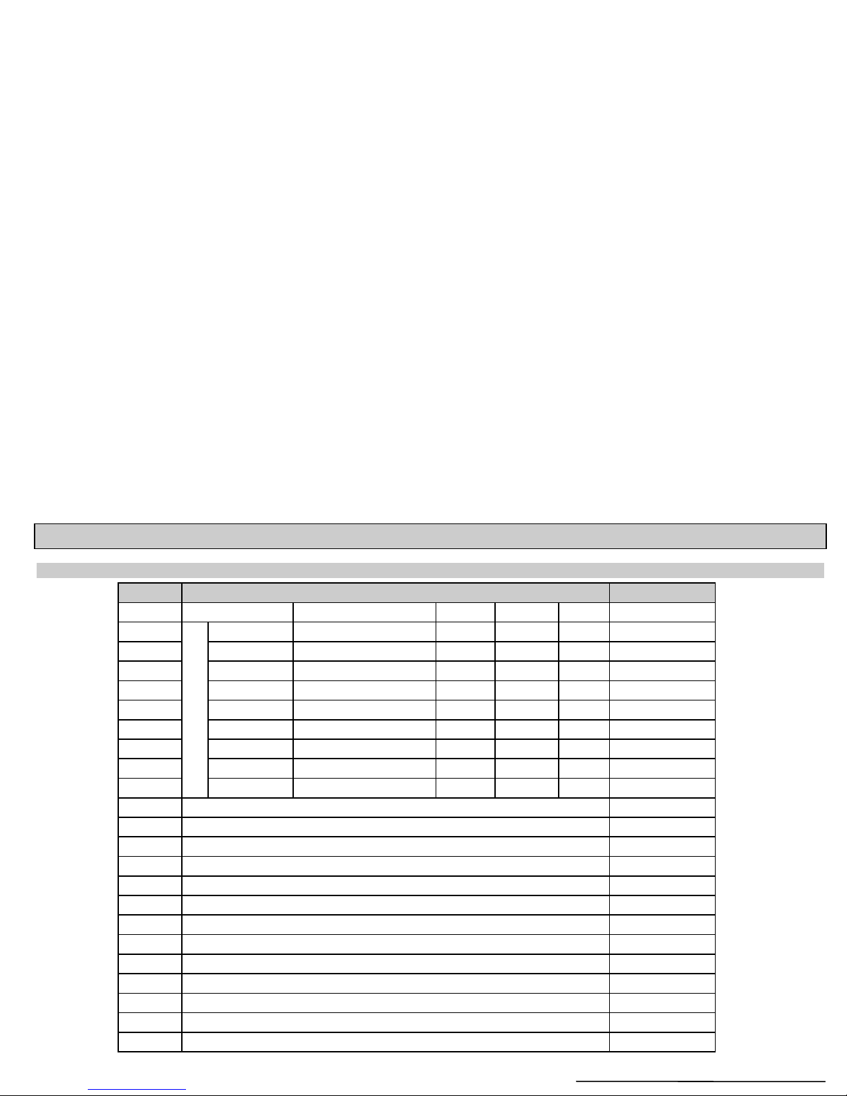
3. TABLE OF PARAMETERS
Par. Page Description Code Par. Page Description Code
dcba dcba
P00 2 Application/Engineering Units P28 13 Echo-loss handling
P01 3 Measurement Mode P29 13 Blocking sout of object #1
P02 4 Calculation units P30 - N.A.
P03 4 Values Displayed-Rounding P31 14
Sound velocity at 20°C
P04 5 Maximum measuring distance P32 14 Specific gravity
P05 6 Minimum measuring dist. (Close-end blocking) P33 -N.A.
P06 7 Far-end blocking P34 - N.A.
P07 - N.A. P35 - N.A.
P08 -N.A. P36 -N.A.
P09 - N.A. P37 - N.A.
P10 8 Value assigned to 4 mA current output P38 - N.A.
P11 8 Value to 20 mA current output P39 -N.A.
P12 8 Error indication by the current output P40 15 Tank/silo shape / Appliances, formula, data
P13 9 Relay function P41 15 Tank/silo dimensions / Flume/weir dimensions
P14 9 Relay parameter – Setpoint value P42 15 Tank/silo dimensions / Flume/weir dimensions
P15 9 Relay parameter – Setpoint value P43 15 Tank/silo dimensions / Flume/weir dimensions
P16 9 Relay parameter – Pulse rate P44 15 Tank/silo dimensions / Flume/weir dimensions
P17 - N.A. P45 15 Tank/silo dimensions / Flume/weir dimensions
P18 - N.A. P46 17 Dist. btw. transducer face and level of Q=0
P19 -N.A. P4721 Linearisation
P20 10 Damping P48 - N.A.
P21 - N.A. P49 - N.A.
P22 10 Dome top tank compensation P50 -N.A.
P23 - N.A. P51 - N.A.
P24 11 Target tracking speed P52 - N.A.
P25 11 Selection of Echo in the measuring window P53 -N.A.
P26 12 Level elevation rate (filling speed) P54 - N.A.
P27 12 Level elevation rate (emptying speed) P55 - N.A.

EasyTREK Compact Ultrasonic Level Transmitters 25
Par. Page Description Code Par. Page Description Code
dcba dcba
P56 -N.A. P7822 TOT2 volume flow totaliser (non-resetable)
P57 - N.A. P79 - N.A.
P58 -N.A. P80 -N.A.
P59 - N.A. P81 - N.A.
P60 21 Overall operating hours of the unit P82 - N.A.
P61 21 Time elapsed after last switch-on P83 -N.A.
P62 21 Operating hours of the relay P84 - N.A.
P63 21 Number of switching cycle of the relay P85 - N.A.
P64 21 Actual temperature of the transducer P86 -N.A.
P65 21 Maximum temperature of the transducer P87 - N.A.
P66 21 Minimum temperature of the transducer P88 - N.A.
P67 -N.A. P89 -N.A.
P68 - N.A. P90 - N.A.
P69 - N.A. P91 - N.A.
P70 -N.A. P92 -N.A.
P71 22
Distance of the of Measuring Window
P93
- N.A.
P72 22
Amplitude of the Echo in the Measuring window
P94
- N.A.
P73 22
Echo Position (time) (read out parameter)
P95
- N.A.
P74 22
Signal To Noise Ratio (read out parameter)
P96
- N.A.
P75 22 Blocking Distance P97 - N.A.
P76 22 Head of flow P98 - N.A.
P77 22
TOT1 volume flow totaliser (resetable)
P99
- N.A.

26 EasyTREK Compact Ultrasonic Level Transmitters
4. SOUND VELOCITIES IN DIFFERENT GASES
The following table contains the sound velocity of various gases measured on 20°C.
Gases Sound Velocity (m/s)
Acetaldehyde
C
2H4
O
252.8
Acetylene
C
2H2
340.8
Ammonia
NH
3
429.9
Argon Ar 319.1
Bensol
C
6H6
183.4
Carbon dioxide
CO
2
268.3
Carbon monoxide CO 349.2
Carbon tetrachloride
CCl
4
150.2
Chlorine
Cl
2
212.7
Dimethyl ether
CH
3
OCH
3
213.4
Ethane
C
2H6
327.4
Ethanol
C
2H3
OH
267.3
Ethylene
C
2H4
329.4
Helium He 994.5
Hydrogen sulphide
H
2
S
321.1
Methane
CH
4
445.5
Methanol
CH
3
OH
347
Neon Ne 449.6
Nitrogen
N
2
349.1
Nitrogen monoxide NO 346
Oxygen
O
2
328.6
Propane N.A.
C3H
8
246.5
Sulphur hexafluoride
SF
6
137.8
July, 2001
sca3802a0600p_01
 Loading...