


BKI 11 ATEX 0012 X le00100a0600p_05 1 / 60
AnaCONT
Manufacturer
Phone (36-1) (36-1)
E-mail: sales@nivelco.com www.nivelco.com
:
H-1043 Budapest, Dugonics u. 11.
: 889-0100 Fax: 889-0200
NIVELCO Process Control Co.
LE-100
LP-100
LG-100
Two-wire compact analytical transmitters

2 / 60 le00100a0600p_05 BKI 11 ATEX 0012 X
pH- and ORP- Dissolved oxygen
sensors and transmitters (compact type)
pH- and ORP- Dissolved oxygen
sensors and transmitters (integrated type)

BKI 11 ATEX 0012 X le00100a0600p_05 3 / 60
TABLE OF CONTENTS
1. INTRODUCTION.............................................................................................................................................................................................................................. 5
1.1. APPLICATION ............................................................................................................................................................................................................................ 5
1.2. OPERATION PRINCIPLE............................................................................................................................................................................................................... 5
1.2.1. Characteristics of an ideal pH electrode .......................................................................................................................................................................................................... 5
1.2.2. Characteristics of an ideal ORP electrode....................................................................................................................................................................................................... 6
1.2.3. Characteristics of an ideal DO sensor ............................................................................................................................................................................................................. 6
2. ORDER CODES............................................................................................................................................................................................................................... 7
2.1. CONFIGURATIONS.................................................................................................................................................................................................................... 11
3. TECHNICAL DATA........................................................................................................................................................................................................................ 16
3.1. TECHNICAL DATA OF THE PH ELECTRODES (INCLUDING EX VERSIONS) FOR LP-- INSTRUMENTS ................................................................................. 18
3.2. TECHNICAL DATA OF THE ORP ELECTRODES (INCLUDING EX VERSIONS) FOR LR-- INSTRUMENTS............................................................................. 20
3.3. TECHNICAL DATA OF THE DO SENSORS (INCLUDING EX VERSIONS) FOR LD-- INSTRUMENTS ..................................................................................... 22
3.4. ACCESSORIES......................................................................................................................................................................................................................... 22
4. MAINTENANCE AND REAPAIR................................................................................................................................................................................................... 23
4.1. STORAGE ............................................................................................................................................................................................................................... 23
4.2. PERIODIC SETTING, CALIBRATION AND VERIFICATION .................................................................................................................................................................. 23
4.2.1. Periodic calibration of the pH electrode ......................................................................................................................................................................................................... 24
4.2.2. Verification of the ORP electrode .................................................................................................................................................................................................................. 25
4.2.3. Periodic calibration of the DO sensor ............................................................................................................................................................................................................ 25
4.3. MAINTENANCE OF THE PH AND ORP ELECTRODES .................................................................................................................................................................... 27
4.4. MAINTENANCE OF THE DO SENSOR .......................................................................................................................................................................................... 29
4.5. SOFTWARE UPDATE................................................................................................................................................................................................................. 29
5. INSTALLATION............................................................................................................................................................................................................................. 30
5.1. MOUNTING.............................................................................................................................................................................................................................. 30
5.1.1. Installation of pH and ORP electrodes........................................................................................................................................................................................................... 30
5.1.2. Installation of DO sensor ............................................................................................................................................................................................................................... 31
5.1.3. Special application possibilities of the Integrated type instruments............................................................................................................................................................... 33
5.2. WIRING................................................................................................................................................................................................................................... 34
5.2.1. Wiring of Compact instruments...................................................................................................................................................................................................................... 34
5.2.2. Wiring of Integrated instruments.................................................................................................................................................................................................................... 35
5.3. LOOP CURRENT CHECKING WITH HAND INSTRUMENT.................................................................................................................................................................. 35
5.4. CONDITIONS OF EX APPLICATION .............................................................................................................................................................................................. 35

4 / 60 le00100a0600p_05 BKI 11 ATEX 0012 X
6. PROGRAMMING ........................................................................................................................................................................................................................... 36
6.1. THE SAP-300 DISPLAY UNIT.................................................................................................................................................................................................... 36
6.2. MEASURING WITH THE SAP-300 DISPLAY UNIT.......................................................................................................................................................................... 37
6.3. PROGRAMMING WITH THE SAP-300 DISPLAY MODULE ............................................................................................................................................................... 40
6.3.1. Components of the programming interface ....................................................................................................................................................................................................40
6.3.2. Menu structure................................................................................................................................................................................................................................................41
6.4. PROGRAMMABLE FEATURES DESCRIPTION................................................................................................................................................................................. 42
6.4.1. Basic measurement settings ..........................................................................................................................................................................................................................42
6.4.2. Analogue output .............................................................................................................................................................................................................................................44
6.4.3. Relay output ...................................................................................................................................................................................................................................................45
6.4.4. Digital output...................................................................................................................................................................................................................................................47
6.4.5. Service functions ............................................................................................................................................................................................................................................47
6.5. PH SENSOR CALIBRATION........................................................................................................................................................................................................ 53
6.5.1. Editing one item of the calibration table..........................................................................................................................................................................................................53
6.5.2. Adding an item to the calibration table ...........................................................................................................................................................................................................55
6.5.3. Deleting an element of the calibration table ...................................................................................................................................................................................................55
6.5.4. Reset the calibration table to default ..............................................................................................................................................................................................................55
6.5.5. Calibration procedure .....................................................................................................................................................................................................................................55
6.6. DO SENSOR CALIBRATION....................................................................................................................................................................................................... 56
6.6.1. Calibration of saturated value (100%) ............................................................................................................................................................................................................56
6.6.2. Calibration of Zero point (0%).........................................................................................................................................................................................................................57
6.6.3. Calibration with referential DO instrument......................................................................................................................................................................................................57
6.6.4. Reset the calibration table to default ..............................................................................................................................................................................................................57
6.6.5. Reset Timer....................................................................................................................................................................................................................................................57
6.7. ERROR CODES ........................................................................................................................................................................................................................ 58

BKI 11 ATEX 0012 X le00100a0600p_05 5 / 60
Thank you for choosing a NIVELCO instrument.
We are sure that you will be satisfied throughout its use!
1. INTRODUCTION
1.1. APPLICATION
The AnaCONT compact transmitters, liquid analytical instruments are suitable for high precision measurement and transmission of acidity or alkalinity - pH
(Hydrogen ion concentration) value -, reducing and oxidizing capability - ORP (Oxidation Reduction Potential) value -, or Dissolved Oxygen content of process
water, wastewater, surface water, ground water and drinking water. These measurements can be widely used in industrial practice and could be of great
relevance. In the field of environmental protection or sewage treatment, instruments like that are suitable for measuring the concentration of hazardous
substances (chromium, cyanide). In chemical- and pharmaceutical industry, high precision measurement has utmost importance in the aspect of the technology
(e.g. solvent feed), in many cases it is quality specification standard.
1.2. OPERATION PRINCIPLE
The intelligent signal processing of the electronics calculates the output signal from the voltage output values of the
electrode and the temperature probe, and compensates it to 25°C. This value composes the basis of all output
signals of the instrument.
1.2.1. Characteristics of an ideal pH electrode
he pH electrode immersed into the measured liquid measures a voltage value which is proportional to the hydrogen
ion concentration of the liquid.
0mV output at neutral pH value (pH=7.00)
Positive voltage output in acidic liquids (pH<7)
Negative voltage output in alkaline liquids (pH>7)
Total measuring range is 0-14pH
-59.16mV/pH (Nernst potential) slope at 25 °C
The temperature dependency of the Nernst potential is -0.001984 mV / °C.
600
500
400
300
200
100
0
100
200
300
400
500
600
100° C (74.04 mV/pH)
25° C (59.16 mV/pH)
0° C (54.20 mV/pH)
2 4 6 8 10 12 14
1 3 5 7 9 1 1 13
Because the pH electrodes in deed are not ideal (their properties depend on the design of the electrode, manufacturing tolerances and most of all the age of the
electrode) the parameters differ from the given values above. To achieve reliable pH measurement and accuracy these electrodes must be calibrated from time
to time. The time interval between two calibrations depends on the application conditions where the pH probes are used. Calibration of pH electrodes means
offsetting the displayed value (7.00pH) when gauging neutral buffer solution, and adjusting the slope (pH/mV) by measuring buffer solutions with other pH value
(usually with 4.00pH and 10.00pH value) by adjusting the displayed value to exact 4.00 and 10.00pH, respectively.

6 / 60 le00100a0600p_05 BKI 11 ATEX 0012 X
1.2.2. Characteristics of an ideal ORP electrode
Negative voltage output in liquids with reduction potential,
Positive voltage output in liquids with oxidation potential,
Output voltage is equal to the redox potential (according to the Nernst equation)
pH independent measurement with certain types
To achieve reliable measurement and accuracy, these electrodes have to be thoroughly checked before
installation and during usage from time to time. The time interval between two calibrations depends on the
application and conditions where the ORP probes are used.
1.2.3. Characteristics of an ideal DO sensor
The dissolved oxygen level indicates the amount (in mg/l or ppm) of physically dissolved gas-form oxygen in
liquid phase.
Oxygen-permeable membrane amperometric DC sensor wetted in the measurement medium gives output
urrent proportional to the dissolved oxygen concentration of the medium.
i
air
i
zero
O
utp
ut c
u
rre
n
t
of the DO sensor
Dissolved oxygen (DO), ppm
sat´n0
Slope =
/ppm oxygen
Output current of the
DO sensor
The ideal DO sensor has:
I
zero=0,
Temperature independent output current
Real DO sensor gives off a minimal I
zero
≠0ppm current in case of 0 ppm dissolved oxygen concentration and its oxygen-permeable capability is temperaturedependent. Oxygen-permeable capability of the membrane is increasing according to the increase of the temperature, at 25 °C it can be 4%/°C. Temperature
proportional correction is necessary for reliable measurement.
The DO sensors in deed are not ideal (their properties depend on the design of the electrode, manufacturing tolerances and most of all the age of the electrode),
so the parameters differ from the given values above. To give reliable DO measurement and accuracy these electrodes must be calibrated from time to time. In
case of DO sensors the calibration means that 0 ppm output value have to be set by offsetting in an oxygen-free solution. For DO measurement of other
mediums (for example dry air 20.95%@25°C or oxygen-saturated water) adjustment of slope (nA/ppm) has to done accurately according to the properties of
these mediums.

BKI 11 ATEX 0012 X le00100a0600p_05 7 / 60
2. ORDER CODES
Not all combinations possible!
AnaCONT instruments:
AnaCONT L - -
*
TYPE CODE FUNCTION CODE HOUSING CODE PROBE**
PROC. CONN. /
MATERIAL
CODE OUTPUT CODE
Transmitter E pH P Plastic 1
BSP 1½ “ / PP 1 4 … 20 mA 2
Transmitter +
display
G ORP R Aluminium 2
BSP 1½ “ / PVDF 2 4 … 20 mA / HART 4
Integrated P DO D
NPT 1½ “ / PP 4 4 … 20 mA / Ex 6
NPT 1½ “ / PVDF 5 4 … 20 mA / HART / Ex 8
4 … 20 mA / Relay R
4 … 20 mA / HART / Realy H
PH PROBE CODE ORP PROBE CODE DO PROBE CODE
4xpher112seph 1
4xorrherpseor 1 4x085g0023ydo
/ 20ppm
1
4xphed112seph 2
4xorrhexpseor 2 4x085g0022ydo
/ 10ppm
2
4xphex112seph 3
4xorrheptseor 3
4xpheph314sph 4
4xorrhespseor 4
4xphe1120seph 5
4xorrheppseor 5
4xphes112seph 6
4xorrheklseor 6
4xphep112seph 7
4xphekl112seph 8
* The order code of an Ex version should end in “Ex”!
** Probe selection is detailed in 3rd chapter.
8 / 60 le00100a0600p_05 BKI 11 ATEX 0012 X
The extension unit, adjustment unit and the sensor housing can be ordered to every analytical device, apart from the type of the electrode, measurement
principal and measured quantity. Sensor protection tube is available only for LP--, or LR-- instruments.
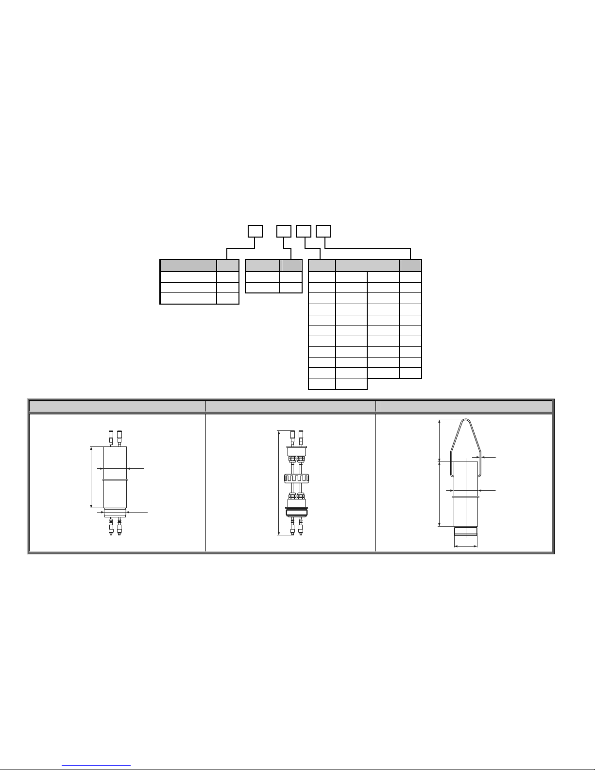
EXTENSIONS L A – – 0
TYPE CODE MATERIAL CODE CODE LENGTH (L) CODE
Pipe R PP 1 0 0 m 0 m 0
Cable K PVDF 2 1 1 m 0.1 m 1
Suspended pipe F 2 2 m 0.2 m 2
3 3 m 0.3 m 3
4 4 m 0.4 m 4
5 5 m 0.5 m 5
6 6 m 0.6 m 6
7 7 m 0.7 m 7
8 8 m 0.8 m 8
9 9 m 09 m 9
A 10 m
PIPE EXTENSION: LAR--0 CABLE EXTENSION: LAK--0 SUSPENDED PIPE EXTENSION: LAF--0
L
=
0
,
2
-
3
m
BSP2"
Ø63
L
=
-
m
1
1
0
101
L = 0,2 - 3m
Ø3
Ø63
BSP2"

BKI 11 ATEX 0012 X le00100a0600p_05 9 / 60
SLIDING SLEEVE: L A A – 1 0 – 0
CODE
DN80 PN16 / PP 2
DN100 PN16 / PP 3
DN125 PN16 / PP 4
DN150 PN16 / PP 5
DN200 PN16 / PP 6
Console mounting bracket, 200 mm K
Mounting bracket, 200 mm T
SLIDING SLEEVE WITH FLANGE: LAA-10-0
DN80 - DN200
63
DO
pH/ORP
CONSOLE MOUNTING BRACKET:
LAA-10K-0
MOUNTING BRACKET: LAA-10T-0
70
20 mm0
Ø
1
2
105
2
Ø
A
101
80
DO
pH/ORP
FOR EXTENSION TYPE
ØA
=63.5MM
FOR BASIC TYPE
ØA
=70.5MM
BKI 11 ATEX 0012 X le00100a0600p_05 10 / 60
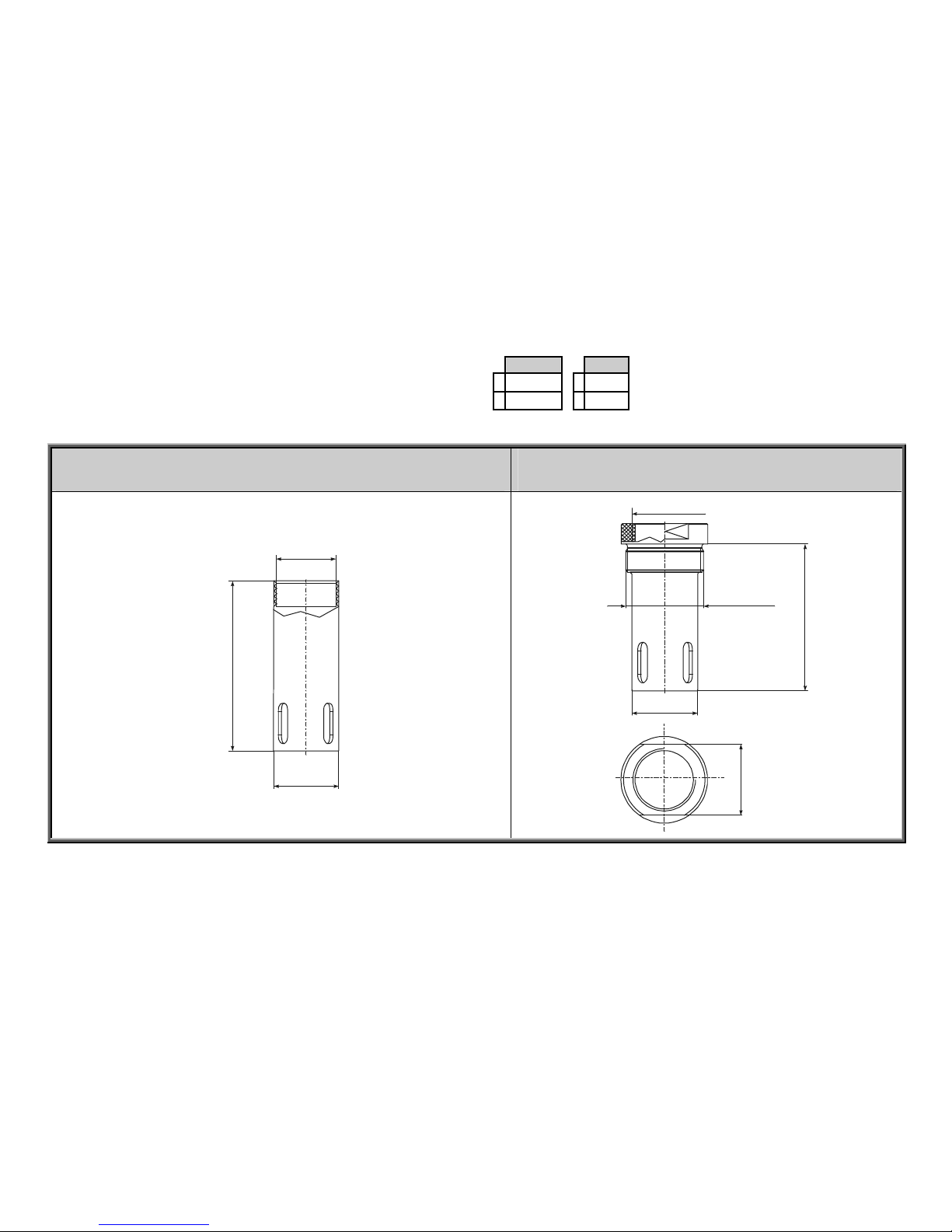
MATERIAL
SIZE
SENSOR PROTECTION TUBE: L A P
–
1 PP 1 1½”
0–0
2 PVDF 2 2”
PROTECTION TUBE 1½”: LAP-10-0
FOR EXTENSION TYPE
PROTECTION TUBE 2”: LAP-20-0
FOR BASIC TYPE
BSP1 1/2"
130
Ø51
55
Ø51
BSP1 1/2"
112
BSP 2"
Sensor protection tube is available only for LP--, or LR-- instruments

BKI 11 ATEX 0012 X le00100a0600p_05 11 / 60
2.1. CONFIGURATIONS
COMPACT STANDARD TYPE: ANACONT LE--,
LG--
(+SENSOR PROTECTION TUBE: LAP-20-0)*
INTEGRATED STANDARD TYPE: ANACONT LP --
(+SENSOR PROTECTION TUBE: LAP-20-0)*
BSP1 1/2"
120 160
~90
120
~200
Ø95
BSP1 1/2"
*Further configuration drawings show only compact types, however many accessories are available to order with integrated types.
Essential dimension values are shown in the drawings of the standard types.

12 / 60 le00100a0600p_05 BKI 11 ATEX 0012 X
STANDARD TYPE: ANACONT L--
(+SENSOR PROTECTION TUBE: LAP-20-0)*
STANDARD TYPE: ANACONT L--
+ PIPE EXTENSION: LAR--0
(+SENSOR PROTECTION TUBE: LAP-10-0)*
~90
BSP1 1/2"
1
0
pH/ORP
112
BSP2"
BSP1 1/2"
DO
1
6
0
1
2
0
52
90
108
As per order
codes
BSP 1 ½"
120
pH/ORP
DO
10
Ø51
Ø63
* Sensor protection tube is available only for LP--, or LR-- instruments.

BKI 11 ATEX 0012 X le00100a0600p_05 13 / 60
STANDARD TYPE : ANACONT L--
+ PIPE EXTENSION : LAR--0
+ SLIDING SLEEVE WITH FLANGE: LAA-10-0
(+SENSOR PROTECTION TUBE: LAP-10-0)*
STANDARD TYPE: ANACONT L--
+ PIPE EXTENSION: LAR--0
+ CONSOLE MOUNTING BRACKET: LAA-10K-0
(+SENSOR PROTECTION TUBE: LAP-10-0)*
52
As per order codes
BSP 1 ½"
120
DO
Ø51
90
108
10
pH/ORP
52
90
108
As per order codes
BSP 1 ½"
120
pH/ORP
DO
10
Ø51
* Sensor protection tube is available only for LP--, or LR-- instruments.

14 / 60 le00100a0600p_05 BKI 11 ATEX 0012 X
STANDARD TYPE ANACONT L--
+ CABLE EXTENSION: LAK--0
(+SENSOR PROTECTION TUBE: LAP-20-0)*
STANDARD TYPE: ANACONT L--
+ CABLE EXTENSION: LAK--0
+ SUSPENDED PIPE EXTENSION: LAF--0
(+SENSOR PROTECTION TUBE: LAP-10-0)*
98
BSP 1 ½"
120
pH/ORP
DO
10
112
BSP2"
BSP1 1/2"
90
175
A
s per order
codes
120
DO
90
175
As per order
codes
As per order
codes
1 ½"
52
110
Ø63
10
Ø51
BSP1 ½"
pH/ORP
* Sensor protection tube is available only for LP--, or LR-- instruments.

BKI 11 ATEX 0012 X le00100a0600p_05 15 / 60
STANDARD TYPE: ANACONT L--
+ CABLE EXTENSION: LAK--0
+ SUSPENDED PIPE EXTENSION: LAF--0
+ SLIDING SLEEVE WITH FLANGE: LAA-10-0
(+SENSOR PROTECTION TUBE: LAP-10-0)*
STANDARD TYPE: ANACONT L--
+ CABLE EXTENSION: LAK--0
+ SUSPENDED PIPE EXTENSION: LAF--0
+ CONSOLE MOUNTING BRACKET: LAA-10K-0
(+SENSOR PROTECTION TUBE: LAP-10-0)*
52
As per order codes
BSP 1 ½"
120
pH/ORP
DO
10
90
175
A
s per order
codes
45
from
DN80
Ø51
BSP1 ½"
52
As per order codes
BSP 1 ½"
120
pH/ORP
DO
10
Ø51
BSP1 ½"
90
175
A
s per order
codes
* Sensor protection tube is available only for LP--, or LR-- instruments.

16 / 60 le00100a0600p_05 BKI 11 ATEX 0012 X
3. TECHNICAL DATA
GENERAL DATA
Material of sensor housing Polypropylene (PP), PVDF
Electrode As per order code
Housing material
Compact type: Plastic: Glass fibre plastic PBT Metal: Powder paint coated Aluminium
Integrated type: Same as the sensor housing
Medium temperature
(pressure dependent) *
PP sensor housing: –10 °C ... +90 °C,
PVDF sensor housing: -15 °C …. +100 °C
with DO probe: 0 °C ... +50 °C
Ambient temperature Metal housing: -30 °C …+70 °C, Plastic housing: -25 °C … +70 °C, both with display: -20 °C … +70 °C
Pressure (absolute)*
With pH and ORP probe: 0.05 … 1 MPa (0.5 … 10 bar) @25°C
With DO probe: 0,1…0,2 MPa (1…2 bar)@25°C
Sealing PP sensor housing: EPDM. all other sensor housing: FPM (Viton)
Ingress protection
Compact type: Sensor housing: IP 68, Housing: IP 67 (NEMA 6)
Integrated type: IP 68
Power supply / Consumption 12 … 36 V DC / 48 mW … 720 mW, galvanic isolation, protection against surge transients
Electrode input
With pH and ORP probe: Combined electrode, galvanic isolation, input impedance: >10
12
ohm, connection: SN6.
With DO probe: Galvanic isolated current input, 0.725V polarisation voltage, connection: SN6
Liquid potential (complementary) electrode** Stainless steel housing of the temperature sensor (1.4571) , connection: SN6
Temperature measuring
(semiconductive sensor)
Range: -50…130°C, Accuracy: ±0.5°C, Resolution: 0.1°C
Analogue: 4 … 20 mA, (3.9 … 20.5 mA), R
tmax
= 1200 Ώ ( [Ut – 12 V] / 0.022 A)
galvanic isolation, protection against surge transients
Relay: SPDT 30 V DC, 1A DC
Display: SAP-300 (128x64 pixels monochrome LCD, 41x24mm with effective display interface)
Outputs
Serial line: (optional) HART interface, terminal resistor 250 ohm
Electrical connections
Compact type: 2 x M20x1.5 metal cable gland, cable diameter: 7 … 13 mm, or 2 x M20x1.5 plastic cable gland, cable
diameter: 6 … 12 mm; connecting cable cross section: 0.5 ... 1.5 mm
2
(shielded cable is recommended) +
internal thread 2x NPT 1 / 2" cable protective pipe
Integrated type: 6x0.5mm
2
shielded cable 6 mm x 5 m (up to max. 30 m cable length)
Electrical protection Class III. electric shock protection, less than 24V voltage feed
* Depends on the selected electrode!
**In case of LP-- and LR-- instruments.

BKI 11 ATEX 0012 X le00100a0600p_05 17 / 60
M
EASUREMENT DATA
pH measurement
Range: 0…14pH, Reserve: ±2pH, Accuracy*: 0.1% of the measured value ±1 digit ±0.01% /°C,
Linearity: ±0.004pH, Resolution: 0.01pH, (internal resolution 0.004pH), Measuring cycle: 300msec, on display: 1 sec
ORP measurement
Range: ±1000mV, Reserve: ±200mV, Accuracy*: 0.1% of the measured value ±1 digit ±0.01% /°C,
Linearity: ±0.001%, Resolution: 0.1mV, Measuring cycle: 300msec, on display: 1sec
DO measurement
Range: 0…20ppm v. 0…10ppm, Reserve: 20%, Accuracy*: 0.5% of the measurement range ±1 digit ±0.01% /°C,
Linearity: ±0.05ppm, Resolution: 0.01ppm, (internal resolution 0.005ppm), Measuring cycle: 300msec, on display: 1sec
* Depends on the selected electrode / sensor!
S
PECIAL DATA FOR EX APPROVED MODELS
Ex marking
II1G Ex ia IIB T6 Ga
Intrinsically safe data
Ci ≤ 15 nF, Li ≤ 200
H, Ui ≤ 30 V, Ii ≤ 140 mA, Pi ≤ 1 W
For Ex transmitter only Ex ia power supply should be used
Ex power supply Uo < 30 V, Io < 140 mA, Po < 1 W, power supply voltage range 12 V … 30 V, Rt
max
= [Ut – 12 V] / 0.022 A
Medium temperature
With pH and ORP probe: for PP sensor housing: –10... +70 °C, PVDF sensor housing: –15... +80 °C
With DO probe: : 0… +50 °C
Ambient temperature Metal housing: -30 °C … +70 °C with display: -20 °C … +70 °C, Plastic housing : -20 °C … +70 °C

18 / 60 le00100a0600p_05 BKI 11 ATEX 0012 X
3.1. TECHNICAL DATA OF THE PH ELECTRODES (INCLUDING EX VERSIONS) FOR LP-- INSTRUMENTS
Type 4xpher112seph 4xphed112seph 4xphex112seph
Range [pH] 1...12 1...12 1...12
Process temperature °C 0…80 0…80 0…100
Max. process pressure [bar] 6 8 16 (<25°C), 6 (<100°C)
Min. conductivity µs/cm 50 150 500
Diaphragm (the conductive aperture of the reference
electrode)/electrolyte in closed glass-house
PTFE (Teflon) ring / 3 mol KCl 2 pcs ceramic rod / 3 mol KCl Concentrical gap/ 3 mol KCl
Connection / insertion length [mm] SN6 & PG13,5 / 120 SN6 & PG13,5 / 120 SN6 & PG13,5 / 120
Main application areas
Public and industrial
wastewater, process water,
drinking water, water in
chemical industry, water with
suspended solid particles.
Industrial water, drinking water,
slightly contaminated
wastewater, cooling tower
water, galvanic industry,
technologic water with Cr 6+,
CN
Wastewater, process water, water
in chemical industry, emulsions,
suspensions, mediums containing
proteins or sulphides, water with
high concentration of solid
particles.
Not applicable for
Steam sterilization, water with
low conductivity, sudden
temperature changes.
Steam sterilization, water with
low conductivity, sudden
temperature changes.
Steam sterilization, water with low
conductivity, sudden temperature
changes. Clear water!!
Type 4xpheph314sph 4xphe112seph 4xphes112seph
Range [pH] 3...14 1...12 1...12
Process temperature °C 0…100 0…60 0…60
Max. process pressure [bar] 6 (<25°C), 3 (<100°C) 0.5 3
Min. conductivity µs/cm 150 150 150
Diaphragm (the conductive aperture of the reference
electrode)/electrolyte in closed glass-house
Ceramic / 3 mol KCl Ceramic / 3 mol KCl Ceramic / 3 mol KCl
Connection / insertion length [mm] SN6 & PG13.5 / 120 SN6 & PG13,5 / 120 SN6 & PG13,5 / 120
Main application areas
Monitoring or controlling of
chemical processes of
mediums from neutral to very
alkaline.
Swimming pools, applications
in atmospheric pressure,
drinking water, slightly
contaminated wastewater.
Swimming pools, applications
under pressure, drinking water,
slightly contaminated industrial
and wastewater.
Not applicable for
Steam sterilization, water with
low conductivity, sudden
temperature changes.
Steam sterilization, water with
low conductivity, sudden
temperature changes, above
atmospheric pressure.
Steam sterilization, water with low
conductivity, sudden temperature
changes

BKI 11 ATEX 0012 X le00100a0600p_05 19 / 60
TYPE 4xphep112seph 4xphekl112sph
Range [pH] 1...12
1...12
Process temperature °C 0…80
0…60
Max. process pressure [bar] 6
3
Min. conductivity µs/cm 150
150
Diaphragm (the conductive aperture of the reference
electrode)/electrolyte in closed glass-house
Ceramic / 3 mol KCl
Ceramic (polycarbonate)
Connection / insertion length [mm] SN6 & PG13,5 / 120
SN6 & PG13,5 / 120
Main application areas
Swimming pools, drinking water, process water,
slightly contaminated wastewater, electrolytic
metallization.
Swimming pools, drinking water, process water,
slightly contaminated wastewater.
Not applicable for
Steam sterilization, water with low conductivity,
sudden temperature changes.
Steam sterilization, water with low conductivity,
sudden temperature changes.

20 / 60 le00100a0600p_05 BKI 11 ATEX 0012 X
3.2. TECHNICAL DATA OF THE ORP ELECTRODES (INCLUDING EX VERSIONS)
FOR LR-- INSTRUMENTS
TYPE 4xorrherpseor 4xorrhexpseor 4xorrheptseor
Process temperature °C 0…80 0…100 0…60
Max. process pressure [bar] 6 16 (<25°C), 6 (<100°C) 1
Min. conductivity µs/cm 50 500 150
Diaphragm (the conductive aperture
of the reference electrode)/electrolyte
in closed glass-house
PTFE (teflon) ring / KCl Circular recess / solid electrolyte Ceramic
Connection / insertion length [mm] SN6 & PG13,5 / 120 SN6 & PG13,5 / 120 SN6 & PG13,5 / 120
Main application areas
public and industrial wastewater
process water
drinking water
water in chemical industry
water with suspended solid particles
polluted water
emulsions, mediums containing
sulphides
high pressure applications
drinking water
pools in atmospheric pressure
slightly polluted water
Not applicable for
steam sterilization
water with low conductivity
sudden temperature changes
steam sterilization
water with low conductivity
sudden temperature changes
clean water
steam sterilization
water with low conductivity
sudden temperature changes

BKI 11 ATEX 0012 X le00100a0600p_05 21 / 60
TYPE 4xorrhespseor 4xorrheppseor 4xorrheklseor
Process temperature [°C] 0…60 0…80 0…60
Max. process pressure [bar] 3 6 3
Min. conductivity [µs/cm] 150 150 150
Diaphragm / electrolyte Ceramic Ceramic Ceramic (polycarbonate housing)
Connection / insertion length [mm] SN6 & PG13,5 / 120 SN6 & PG13,5 / 120 SN6 & PG13,5 / 120
Main application areas
swimming pools
drinking water
slightly polluted water
slightly polluted water
drinking water
process water
swimming pools
metallization
chemical applications
swimming pools
drinking water
slightly polluted water
Not applicable for
steam sterilization
water with low conductivity
sudden temperature changes
steam sterilization
water with low conductivity
sudden temperature changes
above atmospheric pressure
mediums containing ozone
steam sterilization
water with low conductivity
sudden temperature changes

22 / 60 le00100a0600p_05 BKI 11 ATEX 0012 X
3.3. TECHNICAL DATA OF THE DO SENSORS (INCLUDING EX VERSIONS) FOR LD-- INSTRUMENTS
TYPE 4x085g0023ydo (20 ppm) 4x085g0022ydo (10 ppm)
DO range [ppm] 0...20 0...10
Process temperature [°C] 0…50 0…50
Max. process pressure [bar] 1 1
Min. speed of medium-flow [m/s] 0,05 0,05
Response time [sec] 110 22
Accuracy [%; ppm] ±0.5 ; 0.1 ±0.5 ; 0.05
Life-span [year] 2-3 2-3
Material/thickness of the membrane PTFE / 125µm PTFE / 50µm
Other materials
PBT/PC, gold, silver, silver-chloride, potassium-
chloride
PBT/PC, gold, silver, silver-chloride, potassium-
chloride
Application area
Fish- and crawfish farms, water conditioning of large
aquariums, Controlling of oxygen concentration in
water-plants, determination of biological condition in
surface water
Potable water production, river monitoring, water
treatment sites, controlling of dissolved oxygen
level in wastewater plants, determination of
biological condition in surface water.
SAP-300 DISPLAY UNIT
Display 128 x 64 pixels monochrome LCD, with 41x24mm effective display surface
Ambient temperature – 20°C…+70°C
Storage temperature – 30°C…+80°C
Housing material PBT fibre glass plastic
3.4. ACCESSORIES
Installation and programming manual,
Warranty Card
Declaration of Conformity,
2 pcs M20x1.5 cable glands,
pH/ORP electrode (as per order code, separately packed with user manual)
DO sensor (as per order code, separately packed with user manual)
SAP-300 display unit (optional)
CD (EViewLight, DataScope softwares)

BKI 11 ATEX 0012 X le00100a0600p_05 23 / 60
4. MAINTENANCE AND REAPAIR
The AnaCONT series do not require maintenance on a regular basis, but the electrode (depending on the application) may need to be checked, cleaned, calibrated
and replaced regularly.
Repairs during or after the warranty period are carried out exclusively at the Manufacturer’s. Equipments sent back for repairs should be cleaned or neutralised
(disinfected) by the User.
All sensors and electrodes including the NIVELCO recommended ones need proper storage, handling and calibration to have long life-time and give reliable
measurement. Improper handling and lack of calibration will lead to unreliable measurement
4.1. STORAGE
DO sensors can be stored (under normal storage conditions) for a period of 12 month without shortening its lifecycle. The lifetime of pH and ORP electrodes is
maximum one year (storage + usage). Prominent ships the electrodes hydrated in a well sealed container with a 3mol/l KCl solution in it. As a result, the membrane
remains wet and the electrode is in ready-to-use state. It is important to keep these containers as they are needed for storing the electrodes during calibration or in
case of transportation. If for any reason the electrodes are taken out of the process they must be put back into the storage containers containing storage liquid.
Notes: Never let the membrane and the diaphragm desiccated. Do not leave the electrode on open air longer than 10 minutes. If the electrode is warm it can
desiccate even within a shorter period of time!
4.2. PERIODIC SETTING, CALIBRATION AND VERIFICATION
The electrode is exposed to different stresses, dependent on the measured medium, its ORP and pH value and the medium temperature.
That is why the electrode needs to be recalibrated (its accuracy needs to be checked) between certain time intervals depending on the application utilizations. The
calibration intervals may vary from few days to several weeks (max. 8 weeks).

24 / 60 le00100a0600p_05 BKI 11 ATEX 0012 X
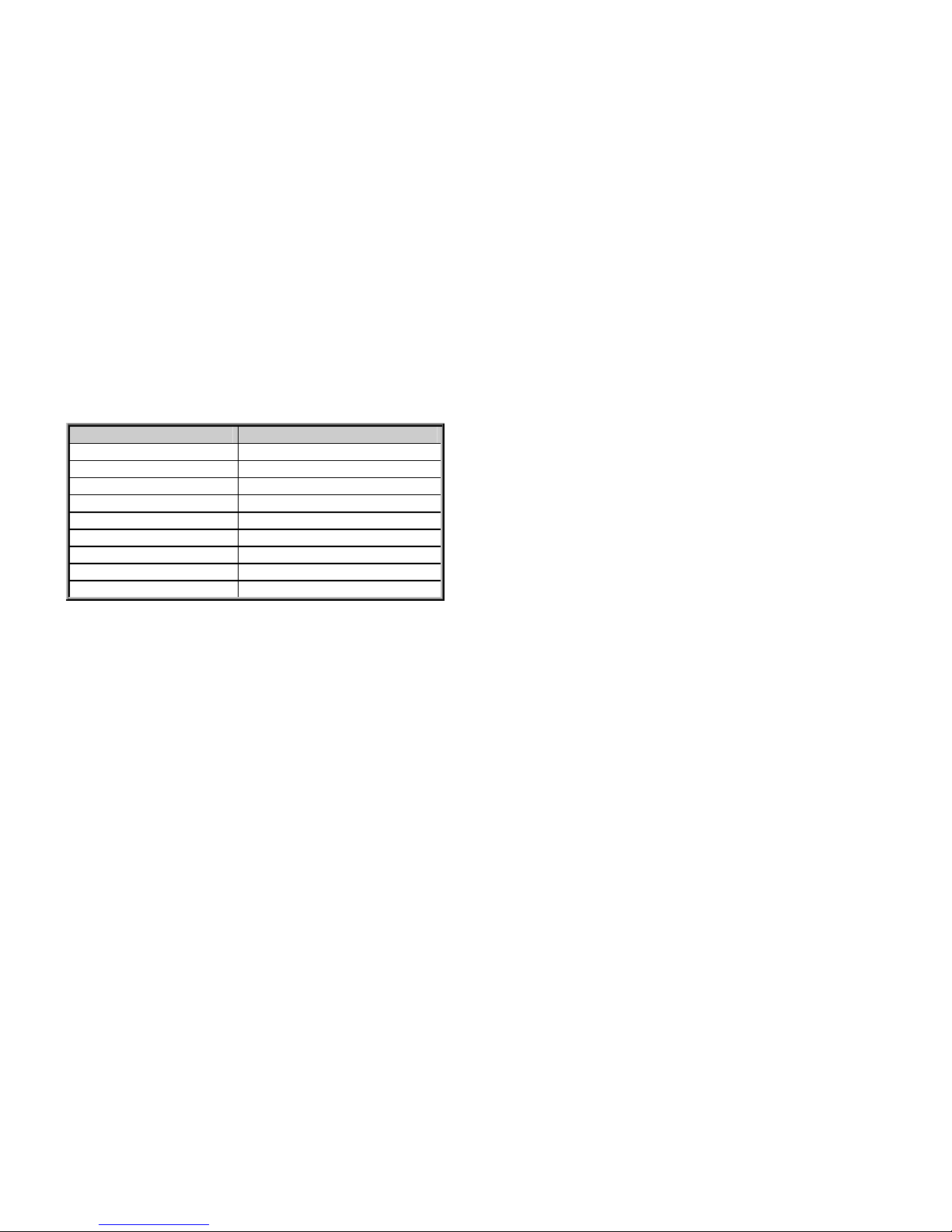
4.2.1. Periodic calibration of the pH electrode
The calibration has to be done minimum in two measuring points (using two different buffer solutions). The calibration points have to be selected so that the widest
measuring range is covered. The common calibration points are 4.00pH and 10.00pH, 4.00pH and 7.00pH, 7.00pH and 10.00pH, or even more points for example
4.00pH, 7.00pH and 10.00pH.
Recommended solutions:
ORDER CODE DENOMINATION
4vpuf4ph50mph Buffer solution pH4 / 50 ml
4vpuf4ph250ph Buffer solution pH4 / 250 ml
4vpuf4ph100ph Buffer solution pH4 / 1 l
4vpuf7ph50mph Buffer solution pH7 / 50 ml
4vpuf7ph250ph Buffer solution pH7 / 250 ml
4vpuf7ph100ph Buffer solution pH7 / 1 l
4vpuf10ph50ph Buffer solution pH10 / 50 ml
4vpuf10ph25ph Buffer solution pH10 / 250 ml
4vpuf10ph10ph Buffer solution pH10 / 1 l
4vtarkcI 350ph Storage solution KCl 3 mol / 50 ml
4vtarkcl 250ph Storage solution KCl 3 mol / 250 ml
4vtarkcl 310ph Storage solution KCl 3 mol / 1 l
4vtiszold 25ph Cleaning solution / 250 ml
The given pH values refer to 25°C. The temperature dependency is given by the manufacturer, usually in a table on the label of the bottle.
The calibration procedure is described in chapter 6.5
BKI 11 ATEX 0012 X le00100a0600p_05 25 / 60
4.2.2. Verification of the ORP electrode
The calibration can be done (for example) with a 465 mV buffer solution. After the electrode is rinsed with distilled water put the electrode into the buffer solution. The
electrode should reach the correct measurement value in 30 seconds. If the measured value is less with more than (the acceptable) 20mV the electrode should be
cleaned. If the electrode does not give the desired measurement after cleaning it has to be replaced
Recommended solutions:
ORDER CODE DENOMINATION
4vpuf22050mor Buffer solution ORP 220 mV / 50 ml
4vpuf220100or Buffer solution ORP 220 mV / 1 l
4vpuf46550mor Buffer solution ORP 465 mV / 50 ml
4vpuf465250or Buffer solution ORP 465 mV / 250 ml
4vpuf465100or Buffer solution ORP 465 mV / 1 l
4vtarkcI 350ph Storage solution KCl 3 mol / 50 ml
4vtarkcl 250ph Storage solution KCl 3 mol / 250 ml
4vtarkcl 310ph Storage solution KCl 3 mol / 1 l
4vtiszold 25ph Cleaning solution / 250 ml
The given (mV) values refer to 25°C. The temperature dependency is given by the manufacturer, usually in a table on the label of the bottle.
4.2.3. Periodic calibration of the DO sensor
The calibration has to be done minimum in two measuring points. Calibration points should be selected according to the required range to cover almost or fully.
In every case it is necessary for the calibration: one solution which does not contain any oxygen – may be a neutral gas – for the zero standard calibration, and an
other solution which has a known oxygen concentration for the full-scale standard calibration.
Zero calibration is necessary, because DO sensor gives output current when the measured medium does not contain any dissolved oxygen. This current is called
residual-current. The required zero-standard is an aqueous solution of sodium-sulphite (Na
2S03
) and cobalt(II)-chloride hexahydrate (CoCl2-6H2O) prepared
according to the followings. Oxygen-free nitrogen gas can be also used as zero-standard. The zero point calibration determines the offset of the calibration line.
Required items:
1 clean pot
1 mixer
1 dl distilled water
1g sodium-sulphite (Na
2S03
)
1mg cobalt(II)-chloride hexahydrate –Analytical Reagent– (CoCl
2
-6H2O)

26 / 60 le00100a0600p_05 BKI 11 ATEX 0012 X
Before the calibration pour the salts in the distilled water with continuous mixing.
For sensitivity calibration it is necessary a full-scale standard to determine the slope of the calibration line. Water solubility of oxygen at atmospheric pressure is well
known dependent on temperature and pressure, so air-saturated water is a natural choice for full-scale standard. The air-saturated water is difficult to prepare and
use. Usage of water-saturated air is a more general practice as a full-scale standard, because air-saturated water and water-saturated air are the same for the DO
sensor. These are same standards, because the sensor is actually measuring the chemical potential of the oxygen. This chemical potential is a force driving through
oxygen molecules from the sample through the membrane into the sensor. Output current of the sensor is proportional to the amount of oxygen driving through the
membrane, so this current is determined by the chemical potential of the oxygen in the sample. The amount of oxygen is the same in air-saturated water and watersaturated air, so the chemical potential of the oxygen are also the same in both phases. Consequently the output current of the sensor is also the same in both
cases.
Automatic calibration on air: The sensor should be simply hold in water-saturated air. The instrument measures the output current of the DO sensor, then store the
measured value if stabilized and measures the temperature of the sample. It determines the saturation vapor pressure of the water from the temperature. Then it
calculates the pressure of the dry air as the difference of atmospheric pressure and the saturation vapor pressure of the water. (Value of atmospheric pressure
should be entered in the menu of the instrument as a parameter, default value is 1013mbar=101,3kPa) Considering the fact, that oxygen concentration of dry air is
20.95%, it calculates the partial pressure of the oxygen. Knowing the partial pressure of the oxygen, it calculates the amount of atmospheric dissolved oxygen in
equilibrium at a current temperature using the Bunsen solubility coefficient. This calculated value is assigned to the stored output current of the sensor.
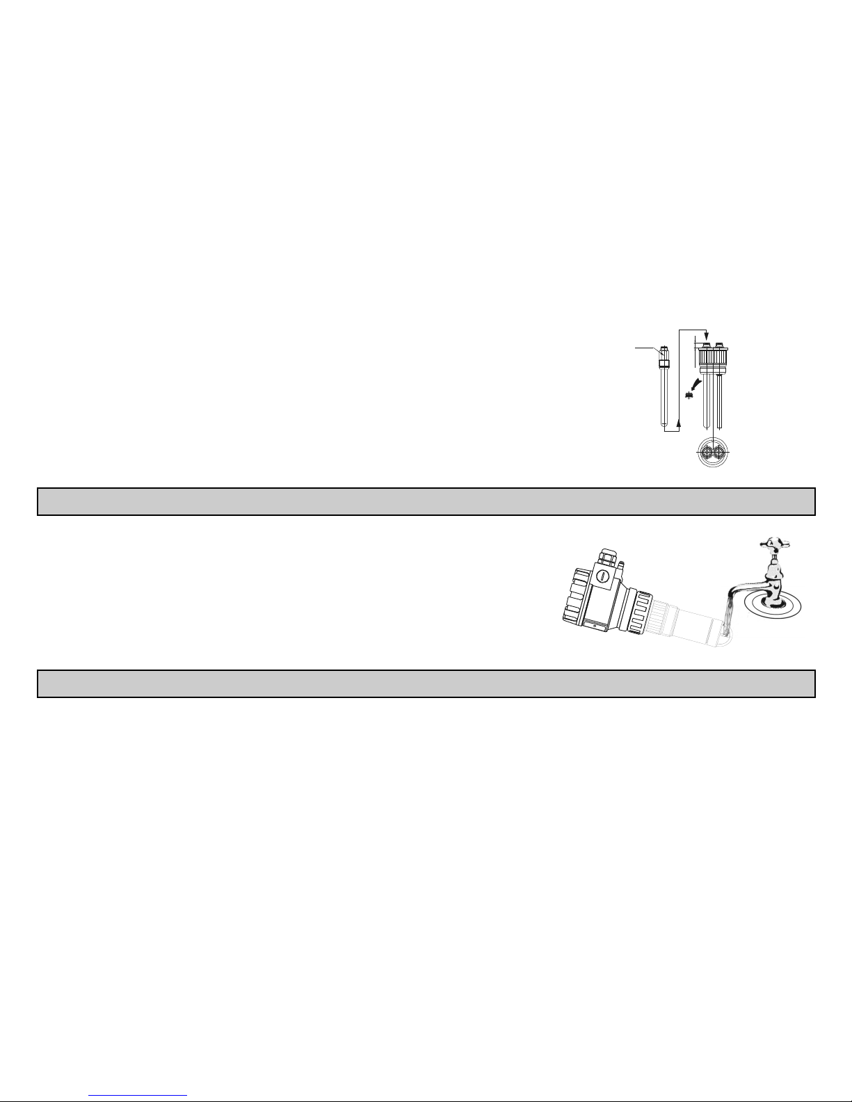
Usually it is has many difficulties to dismount the instrument or the sensor from the technologic process for the calibration. In case of this, the sensor can be
calibrated to a measurement value of a portable laboratory instrument in the same technologic process. Before this type of calibration, the laboratory instrument
(usually also using oxygen-permeable membrane amperometric sensor) should be calibrated in water-saturated air.
The calibration procedure is described in 6.6.

BKI 11 ATEX 0012 X le00100a0600p_05 27 / 60
4.3. MAINTENANCE OF THE PH AND ORP ELECTRODES
In this chapter you can find some recommendations regarding re-hydration, chemical cleaning and reactivation of the electrodes.
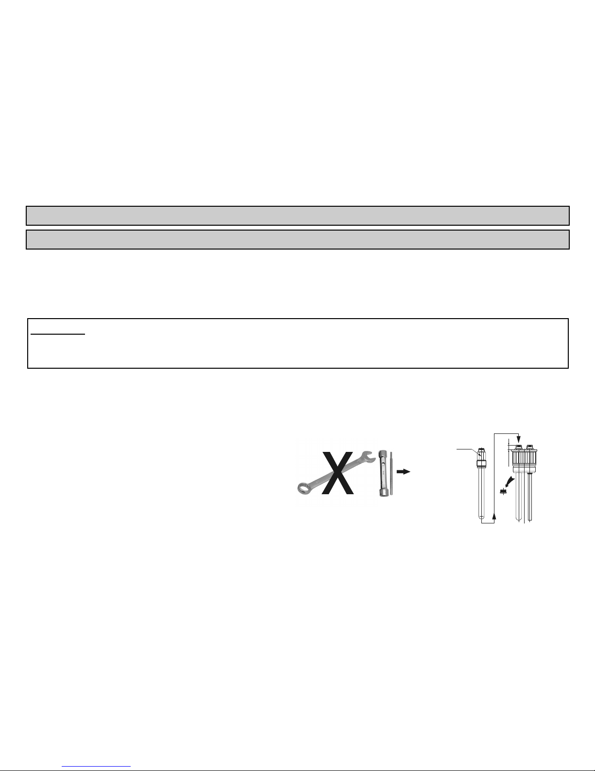
Disassembling the electrode
During this operation be careful not to expose the fragile electrode to mechanical (bending,
squeezing, tensile) forces!
Hold the electrode housing with one hand and the flare nut (right-threaded) with the other one
and loosen it completely.
Then detach carefully the electrode housing from the instrument housing.
Loosen the electrode carefully using a socket-wrench (size 17) and screw it off completely.
Don't use a pipe- or a double-end wrench!
Put the electrode into the storage solution or perform the following steps below.
size 17
Re-hydration
If the electrode was desiccated due to incorrect use or storage it needs to be re-hydrated. This has to be done by soaking the electrode in 3mol/l KCl storage solution
at 20°C for 24 hours. The process can be shortened to 6 hours if the KCl solution is at 60°C.
Note: long time desiccation or desiccation after measuring crystallizating mediums may have an irreversible effect on the electrode and thus the re-hydration may not
be successful.
Chemical cleaning
The deposits and obstructions on the surface of the electrode’s membrane and on the diaphragm have to be eliminated from time to time:
1. General deposits
Rinse the electrode with warm water then dry up gently using a soft rag!
Soak the electrode for 15 mins in 1.5mol/l (5%) hydrochloric acid (HCl)!
Rinse the electrode again with warm water then dry up gently using a soft swab!
Soak the electrode for 1 hour in 3mol/l KCl solution then perform the calibration procedure!

28 / 60 le00100a0600p_05 BKI 11 ATEX 0012 X
2. Non-organic deposits
Rinse the electrode with warm water then dry up gently using a soft rag!
Soak the electrode for 15 mins in 0.1 mol/l EDTA (ethylenediaminetetraacetic acid) solution!
Rinse the electrode again with warm water then dry up gently using a soft rag!
Soak the electrode for 1 hour in 3mol/l KCl solution then perform the calibration procedure!
3. Protein deposits
Rinse the electrode with warm water then dry up gently using a soft rag!
Soak the electrode for 15 mins in 0.5 mol/l hydrochloric acid (HCl) or in 0.1 mol/l HCl and 0.1% pepsin mixture!
Rinse the electrode again with warm water then dry up gently using a soft rag!
Soak the electrode for 1 hour in 3mol/l KCl solution then perform the calibration procedure!
4. Silver sulphide deposits
Rinse the electrode with warm water then dry up gently using a soft rag!
Soak the electrode for 15 mins in 0.1 mol/l thiourea and 1.5 mol/l (5 %) hydrochloric acid (HCl)!
Rinse the electrode again with warm water then dry up gently using a soft rag!
Soak the electrode for 1 hour in 3mol/l KCl solution then perform the calibration procedure!
Note: when deposits are hard to remove try using hydrogen peroxide or sodium hypochlorite solutions.
Reactivation
Regeneration of the glass membrane:
The physical or chemical damage of the glass membrane slows down the operation of the electrode. The reactivation of the membrane helps restoring the normal
operation of the electrode.
Immerse ONLY the spherical part of the glass electrode into ammonium bifluoride with 10% concentration for 60 seconds then immediately
into 50-50% mixture of undiluted HCl and water for 10 seconds. This will neutralize the strong base!
Soak the electrode for 12 hours in 3 mol/l hydrochloric acid (HCl)!
Rinse the electrode with water then dry up gently using a soft rag!
Soak the electrode for 1 hour in 3mol/l KCl solution then perform the calibration procedure!
BKI 11 ATEX 0012 X le00100a0600p_05 29 / 60
Reassembling the electrode
During this operation be careful not to expose the fragile electrode to mechanical (bending, squeezing, tensile) forces!
Insert the electrode to its place carefully, screw it in with your hand and then with a socket-wrench
(size 17) carefully, until it reaches the level of the connector of the temperature sensor
(
0
5.0
5.9
mm
,see figure). Don't use a pipe-wrench or a double-end wrench!
Assemble the instrument housing and the electrode housing then fasten the flare nut with your
hand. Pay attention to the encasement of the anti-rotation guides.
9.5
+ 0
- 0.5
s=17mm
4.4. MAINTENANCE OF THE DO SENSOR
During this operation be careful not to expose the fragile electrode to mechanical forces! Do not
scratch, finger or touch the membrane of the sensor!
Dismount the instrument from the technology process.
While holding the instrument in one hand rinse the membrane of the sensor with clean water.
If necessary some detergents could be used.
Dry up the sensor gently using a soft rag.
4.5. SOFTWARE UPDATE
Based on the observation and needs of our customers NIVELCO constantly improves the operating software of the device. The software can be upgraded with the
help of the ELink (USB) communication adapter plugged into the socket of the SAP-300 display. For software updates and for more information about software
updates please contact NIVELCO.
30 / 60 le00100a0600p_05 BKI 11 ATEX 0012 X
5. INSTALLATION
5.1. MOUNTING
When choosing the installation place please ensure proper space for later calibrations, verification or maintenance service. (see placement on page 32. )
Make sure that the transmitter is protected against overheating that can be caused by direct sunshine.
Assemble the electrode with the instrument prior to the installation.
It is advised to check the operation of the instrument prior to the installation in the control room.
If factory settings need to be modified do it according to the Programming Description.
The process connection should be selected according to the type to be installed.
ATTENTION!
When mounting or dismounting the instrument, avoid exposing the electrodes, DO sensors and temperature sensors to mechanical impacts because
these can cause malfunctioning of the unit. The unit should not be loosened if the process is under pressure, in this case user should take care of
depressurization first!
5.1.1. Installation of pH and ORP electrodes
Prior to mounting into the process the instrument should be put into operation-ready state. For this the user has to insert the electrode (packed separately) into
the instrument as described below:
During this operation be careful not to expose the fragile electrode to mechanical (bending, squeezing, tensile) forces!
The housing of the instrument can be disassembled as described in chapter 4.3.
Remove the plug in the electrode housing from the connector
of the electrode.
Open the box and screw the electrode off the container.
Insert the electrode to its place carefully, screw in with your hand and
using a socket-wrench (size 17) until it reaches the level of the
connector of the temperature sensor (
0
5.0
5.9
mm
).
Don't use a pipe-wrench or a double-end wrench!
size 17
9.5
+ 0
- 0.5
s=17mm
Assemble the instrument as described in Chapter 4.3.
If the instrument is not installed immediately into the process the electrode should be put into storage solution to keep it wet.
BKI 11 ATEX 0012 X le00100a0600p_05 31 / 60
5.1.2. Installation of DO sensor
Prior to mounting into the process the instrument should be put into operation-ready state. For this the user has to insert the DO sensor (packed separately) into
the instrument as described below:
During this operation be careful not to expose the fragile DO sensor to mechanical (bending, squeezing, tensile) forces!
Remove the threaded protector- basket and the sponge-disc protector of the contacts.
Unpack the DO sensor and place it into a flat surface, downward with the plastic cap. Do not wipe the out the silione grease from the back of the
membrane! Silicone grease protect the contacts against short-circuit, even if water is infliltrated.
With one hand hold the instrument upwards with its sensor, with other hand remove the (right-threaded) protector- basket of the sensor.
Place the sensor into the instrument with its cap that the pins of the sensor-nest can fit into the holes in the rear side of the sensor.
Remove the cap from the sensor and replace the protector- basket of the sensor.
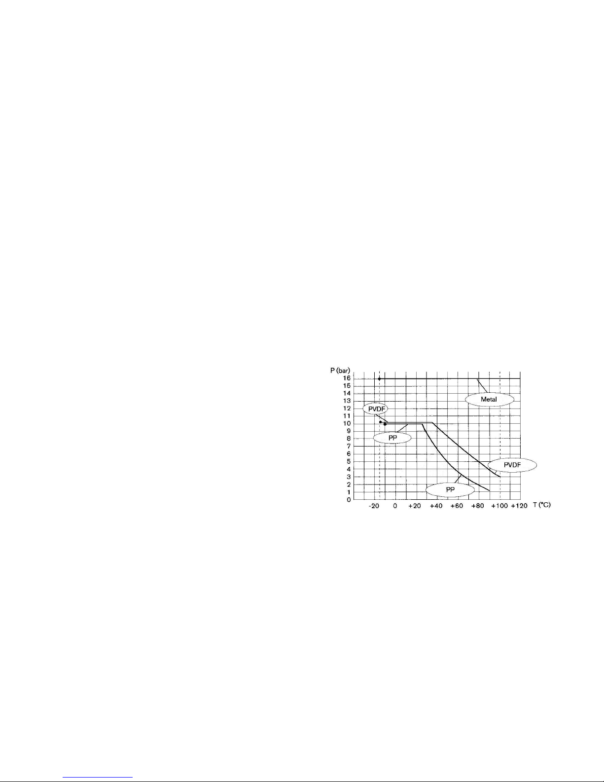
TEMPERATURE
As it is shown in the diagram below – there may be a drop in the pressure-resistance according to the changes of the medium temperature, - which, in any case,
should be considered, prior to the installation of the instrument into the technology process:
Depending on the location of the installation the instrument should be protected
against any heat source or direct sunlight to avoid higher temperatures than
specified!

32 / 60 le00100a0600p_05 BKI 11 ATEX 0012 X
PLACEMENT
The instrument should be mounted within a max. 45° angle, compared to vertical position.
Types mounted with 4xphekl112seph / 4xorrheklseor electrode may be positioned
horizontally as well!
If the unit is installed using a fitting piece the user has to assure that before and after the fitting piece
there is a straight pipe with the appropriate length to minimalize sedimentation and turbulency.
The influent section has to have min. 10xDN length while the effluent section has to have min. 3xDN
length.
It is advised to create a by-pass line so during the service of the instrument the electrode is kept wet
or a calibration can be done without stopping the process.
>10 DN
>3 DN
LIQUID CONTINUITY
Near the electrode (sensor), the pipeline should always be filled with liquid:

BKI 11 ATEX 0012 X le00100a0600p_05 33 / 60
BUBBLE, FOAM
Near the electrode (sensor), liquid in the pipeline should be free of bubbles or foam.
Installation of the threaded models
Screw the unit into its place and tighten by hand. Don’t use any tool!
After tightening, the enclosure can be rotated to the proper position. (Safety bolt prevents rotation more than 350°).
5.1.3. Special application possibilities of the Integrated type instruments
Integrated type instruments can be installed in the same place with the medium to be measured. In this case of application, the maximal process pressure can not
exceed 0.5 bar!

34 / 60 le00100a0600p_05 BKI 11 ATEX 0012 X
5.2. WIRING
The instrument operates from 12.5 … 36 V galvanic isolated and not grounded DC power supply in two wire system. (For Ex version: 12.5 … 30 V DC!)
Sum of the resistance of the equipped instruments, between the transmitter and the power supply, mainly depends on the supply voltage of power supply applied,
and the overall resistance value cannot exceed 1200 ohms. In case of using HART interface – to achieve proper communication between the transmitter’s interface
and the power-supply – a minimal 250 ohms resistance should be maintained within the network.
5.2.1. Wiring of Compact instruments
The instrument should be wired with shielded cable led through the cable gland. The wiring of
cables can be done after removing the cover of the instrument and the SAP display unit.
Make sure that the power supply is turned off at the source.
After removal of the cover of the housing and taking the display module (if any) out,
the wiring cables can be connected. (Recommended cable: shielded, two-wire, with
0.5 ... 1.5 mm2 cross section. Connect shielding to grounding by the inner or outer
grounding screw first.
Switch on the unit. After switching of the unit, necessary programming can be done.
After the wiring, adjustment and programming, check proper sealing and close the
cover carefully.
IMPORTANT: - The housing of the transmitter should be grounded to the EPH network.
Resistance of the EPH network should be R 2 ohm measured from the neutral. Shielding of
the cable should be grounded at the control room side to the EP network. To avoid disturbing
noises, keep away of closeness to high-voltage cables. Especially critical can be the inductive
couplings of harmonics (which are present at frequency converter control) because even cable
shielding does not supply effective protection against these cases.
RELAY
Display unit
connector
Loop current
measuring connect or
4...20 mA loop current
and supply (HART)
GND
1/2” NPT
1/2” NPT
M20x1,5
M20x1,5
I
23456
C2
5
4 6
C1
(Only normal
version)
2 3
1
2
U
1
!
The instrument may be damaged by electrostatic discharge (ESD) via its terminal, thus apply the precautions commonly used to avoid electrostatic
discharge e.g. by touching a properly grounded point before removing the cover of the enclosure.

BKI 11 ATEX 0012 X le00100a0600p_05 35 / 60
5.2.2. Wiring of Integrated instruments
The insrument can be connected directly to the suitable power suply unit. When extending the
cable, a junction box is needed to use for this purpouse. Shielding should be connected with
the shield of the extending cable and should be grounded at the signal processing device.
Make sure that the power supply is turned off at the source.
(Recommended cable: shielded cable with 6 x 0.5 mm
2
or greater cross section).
Turn on the power supply. After switching of the unit, necessary programming can be
done.
Colour codes of the wires:
Green – C1 relay output White – I One point (polarity-independent) of
loop current, power supply and HART
Yellow – CC relay output Brown – I Other point (polarity-independent) of
loop current, power supply and HART
Grey – C2 relay output Black – GND Grounding and shielding point
White
Green
Yel lo w
Grey
Braun
Black
Function box
Power
supply
Power supply
+HART
+Current output
HART modem
I
white (brown)
brown (white)
green
black
R
C1 C2
CC
yellow
grey
TRA NSM IT TER
mA
IMPORTANT: The shielding of the transmitter should be grounded at the control room side to the EPH network. Resistance of the EPH network should be R 2
ohm measured from the neutral. To avoid disturbing noises, keep away of closeness to high-voltage cables. Especially critical can be the inductive
couplings of harmonics (which are present at frequency converter control) because even cable shielding does not supply effective protection against
these cases.
5.3. LOOP CURRENT CHECKING WITH HAND INSTRUMENT
After removing the cover and lifting the Display Module, the actual loop current can be measured with an accuracy of ~ 5% by connecting a voltmeter (in the range of
200 mV) to the points indicated on the drawing above.
5.4. CONDITIONS OF EX APPLICATION
Intrinsically safe units with Ex ia IIB marking can only be used in certified intrinsically safe loops with the previously given technical data. (see values in special
data for Ex approved models under Point 3).
The size of the macrolon window of intrinsical safe equipment with metallic enclosure exceeds the limit, thus the devices must be protected against electrostatic
charges.
Equipment with plastic housing are susceptible to electrostatic charges, thus the deivces must be protected against electrostatic charges.
The aluminium content of equipment with metallic enclosure exceeds the limit, the devices must be protected against impact and friction effects.
Devices should be grounded by connecting their grounding screws to the equipotential system.

36 / 60 le00100a0600p_05 BKI 11 ATEX 0012 X
6. PROGRAMMING
The AnaCONT instruments can be programmed with the SAP-300 display unit.
Without SAP-300 the following LEDs can be seen:
RELAY Indicates the energised state of the relay (C2 closed, C1 open)
VALID Indicates the measuring capability of the unit. If lit, the input signal is stabilised.
If blinking,the input signal is changing.
COM Indicates digital (HART) communication. During Remote programming LEDs are
continuously illuminated.
When SAP-300 display is present, LEDs are not visible; functions are taken over by the display. In default state SAP
display shows the primary measured value (which the output current is calculated from). Programming is supported by
a text-based menu. Navigation is done by using the
E
/ / / buttons.
The instrument can operate without the SAP-300 module as well. Programming can be done only by using SAP-300
display module locally or by HART (REMOTE PROGRAMMING) communication system remotely.
6.1. THE SAP-300 DISPLAY UNIT
The SAP-300 is a 64x128 dot-matrix LCD display which can be plugged into the transmitter. (Universal – usable in
other NIVELCO devices as well – provided that the system software supports SAP-300.)
Warning!
The SAP-300 module is based on LCD technology, so please make sure it is not exposed to permanent heat or direct
sunlight, in order to avoid damage of the display unit. If the instrument cannot be protected against direct sunlight or
high temperature that is beyond the standard operating temperature range of the SAP-300, please do not leave the
SAP display in the instrument.

BKI 11 ATEX 0012 X le00100a0600p_05 37 / 60
6.2. MEASURING WITH THE SAP-300 DISPLAY UNIT
Elements of the display:
1. Primary value (PV), in a dimension depended on the type of the instrument
2. SENSOR VOLTAGE – informative data in case of pH measurement
3. Trend direction arrows. The empty triangle shows when the measured value is small, the filled triangle shows
large-scale change. If none of the arrows are shown the measured value is constant.
4. Measured value in relation to measurement range (Sensor range) in a bargraph.
5. Temperature is shown for temperature compensation (measured by internal sensor).
After the dimension, the temperature compensation mode is indicated by inverse inscription:
Any possible errors during measurement are shown in the lower part of the display.
Manual mode (see 6.4.1.3)
Temperature simulation active (see 6.4.5.8)
Temperature sensor error. In this case the instrument will compensate to 25 ºC.
6. Indication of primary value simulation. In this case the display and output will show the values of the simulation
and not the measured value.
7. Measured value normalized to 25˚C, 760Hgmm and Salinity=0 – informative data (only for DO transmitters)
8. Oxygen saturation (only for DO transmitters)
During active simulation the critical measurement errors will be displayed to give information to the user.
pH measurement
F
ORP measurement
DO measurement

38 / 60 le00100a0600p_05 BKI 11 ATEX 0012 X
A. Calculated value of the output current. After the dimension, the mode of current output is indicated by inverse
inscription:
Manual mode (see 6.4.2.1)
H
HART address is not 0, so output current has become overwritten to 4mA (see 6.4.2.1)
Analogue transmission reacts to a programmed failure condition if an upper or lower fault current is programmed.
(see 6.4.2.4)
B. Output range (4…20mA) indicated in a bargraph.
C. Relay state indication: if deenergized – C1 closed, C2 open, there is no indication. If RELAY message is visible, the relay is energised – C2 closed, C1 open.
D. Indication of Menu Lock:
If key symbol is visible, the unit is protected with a password. When entering the menu, the instrument asks for the correct password.
If REM message is visible, the instrument is in remote programming mode and the menu cannot be accessed.
Errors occurred during the measurement can be seen at the bottom line of the display.

BKI 11 ATEX 0012 X le00100a0600p_05 39 / 60
Information displays:
Press button to cycle between the information displays.
1. The general information display (DEV. INFO): overall
running time (OV. RUN TIME), run time after power on
(RUN TIME), type of interface (INTERFACE), relay
(RELAY) and logger (LOGGER) indication.
2. Sensor information: time passed after last sensor
change, slope and offset after sensor change, time
passed after last calibration, slope and offset at last
calibration, minimum / maximum temperature of the
sensor.
In case of DO measurement in addition to these:
atmospheric pressure (PRESSURE) and salinity
(SALINITY).
3. Relay information: number of switchings, total energised
time (C2 closed) (only if there is a relay in the unit).
The informative display switches back to main screen after 30
seconds.
By pressing the
button the user can get back to main screen at
any time.
Pressing the E button in any of the displays the user can enter to
menu. After exiting the menu always the main screen will be
shown.
Information display of pH
measurement
RUN TIME: 0.1h
OV. RUN TIME: 1.0h
RELAY: YES
INTERFACE: HART
- DEV. INFO ---0:1.00
LOGGER: NO
EN. TIME 15.2h
SW. COUNT 11
STATE: ON
--- RELAY INFO ------
T : 26.5°C
Io: 12.00mA
RELAY
0
F
700mV
S1: 00mV
RUN TIME: 42d
RUN TIME: 5d
-- LAST CALIBRATION -
--- SENSOR INFO -----
SC: 03mV
T: -5°C/ 70°C
Information display of ORP
measurement
Information display of DO
measurement

40 / 60 le00100a0600p_05 BKI 11 ATEX 0012 X
6.3. PROGRAMMING WITH THE SAP-300 DISPLAY MODULE
When entering the menu the instrument makes a copy of the actual parameters, all changes are done to this duplicated parameter set. During programming the
instrument keeps measuring and transmitting with the current (and intact) parameter set. After exiting the menu the instrument replaces the original parameters with
the new parameter set and will measure according the new parameters. This means that the change of the parameters does not become immediately effective when
pressing the E button!
Entering the menu can be done by pressing the E button while exiting the menu can be done by pressing the button.
If the instrument is left in programming mode after 30 mins it will automatically return to measuring mode. If the SAP display is removed during programming the
instrument immediately returns to measuring mode.
As programming with SAP-300 (manual programming) and HART (remote mode) programming is not possible at the same time use only one programming method
at a time. Measured values can be read out through HART at any time
6.3.1. Components of the programming interface
The parameters of the instrument are grouped according to their functions. The programming interface consists of lists, dialog windows, edit windows and report
windows.
Lists
Navigation between the lines of a list can be done by pressing / buttons. Pressing the E button
activates a list item. Selected list item is marked with inverse colour. Exit from a list by pressing the
button.
Menu list
Menu list is a specialized list. Its characteristic is that upon selecting a list item we directly get into another list,
and these lists are opening from each other in different levels.
The menu header (1) helps to navigate.
Entering the menu can be done by pressing the E button. Navigation between the menu items can be done
by pressing the
/ buttons. Enter to the selected menu by pressing the E button. The selected list item
is marked with inverse colour.
Exit from a submenu with
button. Pressing the button in the main menu will exit programming mode and
the instrument will return to measuring mode.

BKI 11 ATEX 0012 X le00100a0600p_05 41 / 60
Dialog window
The system sends messages or warnings using dialog windows. These usually can be acknowledged by
pressing the
button or the user can choose between two options (usually YES or NO) by pressing /
buttons. In some cases to correct an error one of the parameters has to be changed
WARNING
LOAD DEFAULT TO
PARAMETER TABLE!
ARE YOU SURE?
[YES] [NO]
Edit window
An edit window is used for modifying a numeric parameter value. The selected character can be changed
using the
/ buttons. The cursor can be moved to left, using the button.
The direction of the cursor movement through the digits is right to left. Changed value can be validated by
pressing the E button. The software checks if the entered value is appropriate, exiting the edit window is only
possible after entering a correct value. If the entered value is uninterpretable the software sends an error
message in the bottom line (1) of the display. The display gives the same error message, independently of the
measured value and the measurement principle.
PV: primary Value
Edit window – button combinations
In the edit window the following button combinations are available:
1. Recalling the parameters to the state before editing ( + , pressed for 3 secs);
2. Recalling default parameters (
+ , pressed for 3 secs);
3. Inserting (currently) measured value to the edit window (
+ , pressed for 3 secs)
Only for certain parameters!
6.3.2. Menu structure
Main menu
BASIC SETUP Parameter group of the basic measurement parameters
OUTPUT SETUP Parameter group of the output parameters
SERVICE Service functions, calibration, test and simulation
42 / 60 le00100a0600p_05 BKI 11 ATEX 0012 X
6.4. PROGRAMMABLE FEATURES DESCRIPTION
6.4.1. Basic measurement settings
6.4.1.1 Measuring unit (Only for DO measurement)
Parameter: P02: b
Menu path: BASIC SETUP / MEASURING UNIT Default value:
Dimension of PV: primary value. ppm
ppm
mg/l
%sat
Description:
Primary values are the same in case of displaying ppm and mg/l, only
displayed and transmitted dimension changes. Large number on the screen
follows the dimension of ppm and mg/l in the setting of ppm and mg/l.
In case of choosing %sat, large numbered primary value indicates the oxygen
saturation.
6.4.1.2 Damping time
Parameter: P20
Menu path: BASIC SETUP / DAMPING TIME Default value:
pH
measurement
ORP
measurement
DO
measurement
Description: Damping time is used to damp the unwanted fluctuations of the output and
display.
If the measured value changes rapidly the new value will settle with 1%
accuracy after this set time
2 sec 2 sec 2 sec
6.4.1.3 Temperature compensation mode
Parameter: P06: a
Menu path: BASIC SETUP / TEMP. COMPENSATION / MODE Default value:
AUTO
Description: Mode of the temperature compensation
AUTO Compensation is done with the value measured by the temp. sensor.
MANUAL Compensation is done with a predefined temperature value
(see 6.4.1.5)
OFF No compensation

BKI 11 ATEX 0012 X le00100a0600p_05 43 / 60
6.4.1.4 Temperature compensation unit
Parameter: P02: a
Menu path: BASIC SETUP / TEMP. COMPENSATION / UNIT Default value:
Description: Dimension of the temperature measurement
ºC
ºF
ºC
6.4.1.5 Temperature compensation fixed value
Parameter: P07
Menu path: BASIC SETUP / TEMP. COMPENSATION / MANUAL VALUE Default value:
Description: Value of the manual temperature compensation (see 6.4.1.3)
25 ºC
6.4.1.6 Salinity correction value (Only for DO measurement)
Parameter: P23
Menu path: BASIC SETUP / SALTINITY CORRECTION / MANUAL VALUE Default value:
Description: Value of the salinity correction in ppt (parts per thousand)
0 ppt
6.4.1.7 Pressure correction unit (Only for DO measurement)
Parameter: P02: c
Menu path: BASIC SETUP / PRESSURE CORRECTION / UNIT Default value:
Hgmm
Description: Dimension of the atmospheric pressure correction
Hgmm Compensation is performed by the measured value of the
temperature sensor
bar Compensation is performed by a fix given temperature value.
kPa Compensation is off
Measurement unit is required to be selected first and value should be entered after this.
6.4.1.8 Pressure correction value (Only for DO measurement)
Parameter: P22
Menu path: BASIC SETUP / PRESSURE CORRECTION / MANUAL VALUE Default value:
Description: Value of the atmospheric pressure correction
Measurement unit is required to be selected first and value should be entered after this.
760 Hgmm

44 / 60 le00100a0600p_05 BKI 11 ATEX 0012 X
6.4.2. Analogue output
6.4.2.1 Output current mode
Parameter: P12: b
Menu path: OUTPUT SETUP / ANALOG OUTPUT / CURRENT MODE Default value:
AUTO
Description: Transmission mode of the current output [AUTO, MANUAL]
AUTO The output current is calculated from the measured value, output is
active.
MANUAL The output current is fixed at a constant (set) value (see 6.4.2.5). In
this mode the setting of the error current (see 6.4.2.4) is irrelevant.
The set (current) value overwrites the 4mA output of HART
multidrop mode!
6.4.2.2 Output current value 4mA
Parameter: P10
Menu path: OUTPUT SETUP / ANALOG OUTPUT / 4mA VALUE Default value:
pH measurement ORP measurement DO measurement
Description: Measured value assigned to 4mA
0 pH - 1000 mV 0 ppm
6.4.2.3 Output current value 20 mA
Parameter: P11
Menu path: OUTPUT SETUP / ANALOG OUTPUT / 20mA VALUE Default value:
pH measurement ORP measurement DO measurement
Description: Measured value assigned to 20mA
14 pH 1000 mV 8.24 ppm
6.4.2.4 Output current error mode
Parameter: P12: a
Menu path: OUTPUT SETUP / ANALOG OUTPUT / ERROR MODE Default value:
HOLD
Description: Error indication by the current output
HOLD Error indication has no effect on the output current.
3.8 mA Error indication: the output current gets 3.8mA.
22 mA Error indication: the output current gets 22mA
Attention! Also see chapter 6.4.2.1!

BKI 11 ATEX 0012 X le00100a0600p_05 45 / 60
6.4.2.5 Fixed output current
Parameter: P08
Menu path: OUTPUT SETUP / ANALOG OUTPUT / MANUAL VALUE Default value:
4 mA
Description: Parameter for setting the fixed output current
Values between 3.8 and 20.5 can be entered. The output current will be set to the entered
value and analogue transmission will be suspended. . (see 6.4.2.1)
The set (current) value overwrites the 4mA output of HART multidrop mode!
6.4.3. Relay output
6.4.3.1 Relay output mode
Parameter: P13: a
Menu path: OUTPUT SETUP / RELAY OUTPUT / MODE Default value:
OFF
Description: Relay operating mode:
OFF Relay off (C1 closed, C2 open)
PH/ORP/DO Relay operation assigned to the measured pH / ORP / DO value
TEMP Relay operation assigned to the measured temperature
ON ERROR Relay operates on critical errors
6.4.3.2 Relay output functions
Parameter: P13: b
Menu path: OUTPUT SETUP / RELAY OUTPUT / FUNCTION Default value:
Description: Relay operation functions: HYSTERESIS
HYSTERESIS
Differential control. (ex.: for
controlling tasks)
If the two switching values
are close to each other it will
operate as a limit switch.
C2 OPEN
, T
EN < DEN
DEN EN
C2 CLOSED
PV
C2 CLOSED
C2 OPEN
PV, T
EN > DEN
EN DEN
WINDOW
Window comparator mode
(ex.: for monitoring a range).
H1=H2=0.05pH or 0.05 ºC
, T
H
1
H
2
EN < DE N
DEN EN
C2 CLOSED
C2 OPEN
PV
, T
H
1
H
2
EN > DE N
EN DEN
C2 CLOSED
C2 OPEN
PV
PV: Primary Value – pH measurement: pH, ORP measurement: mV, DO measurement: ppm

46 / 60 le00100a0600p_05 BKI 11 ATEX 0012 X
6.4.3.3 Relay output energised value
Parameter: P14
Menu path: OUTPUT SETUP / RELAY OUTPUT / ENERGIZED VALUE (EN) Default value:
pH measurement ORP measurement DO measurement
Description: Value of the relay when it will become energised (C1 open, C2
closed)
0 pH - 1000 mV 0 ppm
6.4.3.4 Relay output de-energised value
Parameter: P15
Menu path: OUTPUT SETUP / RELAY OUTPUT / DEENERGIZED VALUE (DEN) Default value:
pH measurement ORP measurement DO measurement
Description: Value of the relay when it become deenergised at (C1 closed,
C2 open)
14 pH 1000 mV 8.24 ppm
6.4.3.5 Relay switching (ON/OFF) delay
Parameter: P16
Menu path: OUTPUT SETUP / RELAY OUTPUT / DELAY Default value:
Description: Delay time of the relay switching On or Off (0 – 99 sec)
0 sec
6.4.3.6 Relay inverted operation
Parameter: P13: c
Menu path: OUTPUT SETUP / RELAY OUTPUT / INVERTING Default value:
Description: Relay operation
NO Normal operation
YES Inverted operation
NO

BKI 11 ATEX 0012 X le00100a0600p_05 47 / 60
6.4.4. Digital output
6.4.4.1 HART polling address
Parameter: P19
Menu path: OUTPUT SETUP / SERIAL OUTPUT / ADDRESS Default value:
0
Description: HART polling address (only HART capable types)
The polling address can be set between 0 and 15. For a single instrument the polling
address is 0 and the output is 4...20mA (analogue output). If multiple units are used in
HART Multidrop mode (max. 15pcs) the polling addresses should differ from 0 (1-15), in
this case the output current will be fixed at 4mA. The fixed 4mA output can be overwritten
as described in chapter
6.4.2.5.
6.4.5. Service functions
6.4.5.1 Security codes
User security code
Parameter: -
Menu path: SERVICE / SECURITY / USER LOCK Default value:
0
Description: Setting or unlocking the user security code.
The instrument can be protected against unauthorized programming with a 4 digit PIN
(Personal Identification Number) code. If either of the digits differs from 0 the code is
active. If zero is specified, then the secret code has been deleted!
In case of Active code, this code is requested at menu entry.
Service code
Parameter: Menu path: SERVICE / SECURITY / SERVICE LOCK
Description: Setting of the service code (only for trained personnel)!

48 / 60 le00100a0600p_05 BKI 11 ATEX 0012 X
6.4.5.2 Loop test
Parameter: P80
Menu path: SERVICE/OUTPUT TEST / ANALOG OUTPUT
Description: Loop current test (mA)
Values between 3.9 and 20.5 can be entered. The output current will be set to the entered value. The measured current on the output
should be equal to the set value.
In test mode a dialog window warns the user of the fixed output current until the user exits the warning message window.
Exiting can be done by pressing the
button.
6.4.5.3 Relay output test
Parameter: P81
Menu path: OUTPUT SETUP / TEST / RELAY OUTPUT
Description:
Used for the testing of the relay output. Pressing the
and buttons the relay will change state.
When in this menu point the programmed relay operation is not taken into consideration.
DEENERGIZED Relay is de-energised
ENERGIZED Relay is energised
6.4.5.4 pH Sensor calibration
Parameter: Menu path: SERVICE / SENSOR CALIBRATION
Description: Calibration of the pH sensor (electrode) (see 6.5).
VIEW/EDIT TABLE Table overview
ADD ITEM Addition of a calibration point
DELETE ITEM Deletion of a calibration point
RESET TO DEFAULT Resets the calibration table to default
RESET TIMER Resets the inner timer of the pH electrode life-time monitoring routine. This timer is NOT a real-time
clock. It only counts when the instrument is powered. Its value is saved in a non-volatile memory

BKI 11 ATEX 0012 X le00100a0600p_05 49 / 60
6.4.5.5 ORP Sensor calibration
Parameter: -
Menu path: SERVICE / SENSOR CALIBRATION
Description: Calibration of the ORP sensor.
SET ZERO POINT Setting the zero point of the sensor
1. Measured value (without setting).
2. Real (measured) value at the zero point of the sensor
Use a 0 mV buffer solution. Dip the sensor into the buffer solution and wait until the measured
value (1) becomes stabilised! Set the uncalibrated measured value (1) in the edit field using
the
, and buttons. By pressing and simultaneously the measured value can
be entered to the edit field.
SENSOR SETUP
PARAMETER EDITOR
SET ZERO POINT
3mV mV
00053
1 2
Entering the SERVICE / SENSOR CALIBRATION menu the instrument will display a warning message that the user is about to change
critical parameters of the measurement system. The user can enter the menu by pressing the
(OK) button or exit to the previous menu by
pressing the
(NO) button. In the next dialogue the software asks the user if the calibration of the sensor is the „first” calibration (after a
new sensor is installed) or not. Select OK or NO buttons. If OK button is selected the stored informational parameters of the previous sensor
are reset to default values. Select (NO) button if it is not a „first” setting.
6.4.5.6 DO Sensor calibration
Parameter: -
Menu path: SERVICE / SENSOR CALIBRATION
Description: Calibration of the DO sensor. Calibration process is described at chapter 6.6.
Calibration shall be performed in air or referential liquid, sanity is zero in both cases.
CAL. IN AIR (SPAN) Calibration of saturated value (100%sat) with sensor in air (8.24ppm / [25˚C, 760Hgmm])
CAL. IN ZERO SOL. Calibration of the Zero point in referential liquid.
CAL. IN SPAN SOL. Calibration of the saturated value (100%sat).
RESET TO DEFAULT Resets the calibration table to default
RESET TIMER Resets the inner timer of the pH electrode life-time monitoring routine.
This timer is NOT a real-time clockIt only counts when the instrument is powered. Its value is saved in a non-volatile memory

50 / 60 le00100a0600p_05 BKI 11 ATEX 0012 X
6.4.5.7 Simulation
This function helps the user to check the outputs and the additional processing instruments connected to the output. (Irrespectively of the instruments)
To start simulation the instrument must return to Measuring mode.
Simulation mode
Parameter: P84: a
Menu path: SERVICE / SIMULATION / MODE Default value:
OFF
Description: Simulation mode:
OFF No simulation
FIX VALUE Its value is set according to the lower range value of pH / ORP
simulation
TRIANGLE WAVE
The simulated value changes linearly between the set low and
high values with an adjustable cycle time.
PV: Primary Value
SQUARE WAVE The simulated value jumps between the set low and high values
with an adjustable cycle time.
Simulation cycle
Parameter: P85
Menu path: SERVICE / SIMULATION / TIME Default value:
Description: Cycle time of the simulation
60 sec
Bottom value of the simulation
Parameter: P86
Menu path: SERVICE / SIMULATION / BOTTOM VALUE Default value:
pH measurement ORP measurement DO measurement
Description: Lowest value of the simulation
0 pH - 1000 mV 0 ppm
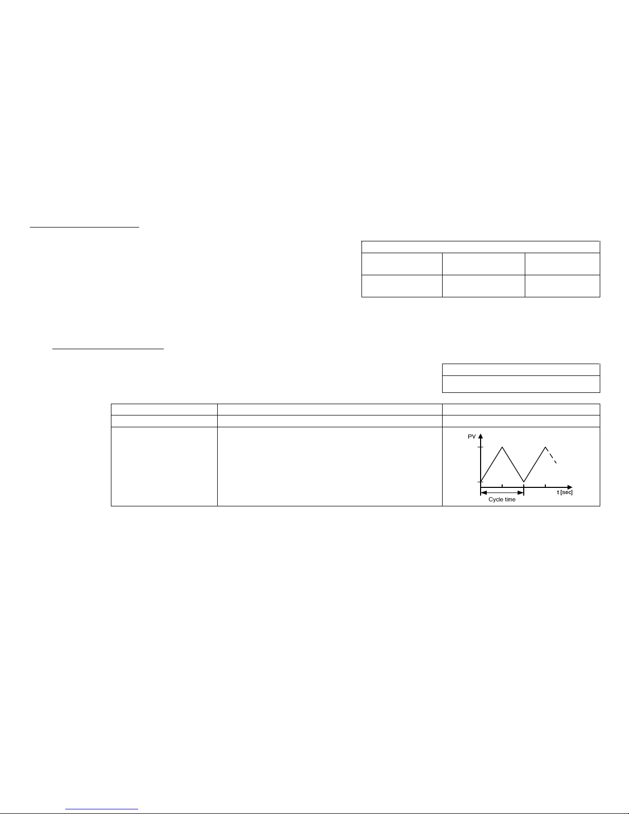
BKI 11 ATEX 0012 X le00100a0600p_05 51 / 60
Upper value of the simulation
Parameter: P87
Menu path: SERVICE / SIMULATION / UPPER VALUE Default value:
pH measurement ORP measurement DO measurement
Description: Highest value of the simulation
14 pH 1000 mV 8.24 ppm
6.4.5.8 Temperature simulation
This function helps the user to check the outputs and the additional processing instruments connected to the output.
To start simulation the instrument must return to Measuring mode.
Temperature simulation mode
Parameter: P84: b
Menu path: SERVICE / TEMP. SIMULATION / MODE Default value:
OFF
Description: Temperature simulation mode:
OFF No temperature simulation
FIX VALUE Simulation of a fixed lower range temperature value
TRIANGLE WAVE The simulated value changes linearly between the set low
and high values with an adjustable cycle time

52 / 60 le00100a0600p_05 BKI 11 ATEX 0012 X
Temperature simulation cycle
Parameter: P88
Menu path: SERVICE / TEMP. SIMULATION / TIME Default value:
Description: Cycle time of the temperature simulation
60 sec
Bottom value of the temperature simulation
Parameter: P89
Menu path: SERVICE / TEMP. SIMULATION / BOTTOM VALUE Default value:
Description: Lowest value of the temperature simulation
0 ºC
Upper value of the temperature simulation
Parameter: P90
Menu path: SERVICE / TEMP. SIMULATION / UPPER VALUE Default value:
Description: Highest value of the temperature simulation
50 ºC
6.4.5.9 Load default values
Parameter: -
Menu path: SERVICE / DEFAULTS / LOAD DEFAULT Default value:
-
Description: This command loads all default values of the instrument.
After loading the default values the parameters can freely be changed, the effect of the
changes does not affect the measurement until the user exits programming mode and
returns to measurement mode. Before loading the defaults the software asks for a
confirmation warning the user that all user parameters will be lost!
6.4.5.10 Restart
Parameter: -
Menu path: SERVICE / RESTART Default value:
Description: Restarts the instrument (Cold boot) (Reloads parameters from the non-volatile memory)
–

BKI 11 ATEX 0012 X le00100a0600p_05 53 / 60
6.5. PH SENSOR CALIBRATION
This function is for periodic calibration of the pH sensor.
Entering the SERVICE / SENSOR CALIBRATION menu the instrument will display a warning message that the user is about to change critical parameters of the
measurement system. The user can enter the menu by pressing the
(OK) button or exit to the previous menu by pressing the (NO) button.
In case of calibration, after sensor replacement, please handle first calibration with high priority. The system will inquire this in the next dialog box. In the event of
initial calibration, press the OK button. In this case, all parameters and counters related to the sensor will be reset to default.
We should press
NO button, in case it is not the first calibration.
In the SENSOR INFO page the slope and offset voltage of the sensor can be checked (see chapter 6.2).
The calibration can be performed within ±0.8 pH sensor error. When this error is greater then ±0.8 pH the unit shows a warning message that the sensor should be
replaced.
6.5.1. Editing one item of the calibration table
(SERVICE | SENSOR CALIBRATION | VIEW/EDIT TABLE)
Calibration of the pH sensor is done using this table with min. 2 or max. 8 elements. By default the table contains
2 elements (0 and 14pH). The instrument is ready to measure with these two elements in the table. Any change in
the calibration table applies instantly! The two minimal elements of the table cannot be erased only edited.
The selected element of the list (table) can be edited by pressing the
E
button. Then we get a special box editor.
One line of the list consists of two values. The left one (BUFFER VALUE) shows the nominal value of the used pH
buffer solution. The right one (SENSOR VALUE) indicates the uncalibrated but temperature compensated value
measured with this buffer solution.
VIEW/EDIT TABLE
0: 0.00 0.00
1: 14.00 14.00

54 / 60 le00100a0600p_05 BKI 11 ATEX 0012 X
Adding, modifying a calibration point
The following special screen helps the user to set a calibration point. The user can see the
uncalibrated measured values and also the pair values of the selected table line.
1. Value, measurable without sensor calibration
2. Trend display for monitoring installation.
The upper part of the bargraph symbolizes the increasing trend, the bottom part of
the bargraph symbolizes the decreasing trend. The filling rate is in accordance with
the measure of change. If the bargraph is empty, the measured value is constant.
3. Measured value with calibration.
4. The BUFFER VALUE is editable using the
, and buttons. The user has to
enter the nominal pH value of the measured buffer solution.
5. The measured value can be copied to the stored SENSOR VALUE by pressing the
+ buttons simultaneously. Then the software starts an algorithm to check if
the measured value is stable or not. When the value is stored in the SENSOR
VALUE field, a READY message appears on the bottom of the display.
The measured value can be copied to the stored SENSOR VALUE by pressing the + buttons simultaneously. If the two values of the data pair differ in more
than ±0.8 pH from each other the software shows an error message at the bottom line of the screen.
By pressing the
E
button the instrument checks the edited calibration data pair and if it is OK the software returns to the calibration table. If not a dialogue window
will appear and inform the user.
Exit from the calibration table by pressing the
button.
Damping check:
When pressing the
+ buttons the software checks if the calibration value to be stored is constant. After the buttons are pressed the measured pH value must
be stabilized in 30 seconds otherwise the value will not be stored and a FAILED! message will appear on the screen. Change in the measured value (1) can be
followed on the trend bargraph (2). If the cause of a fluctuation or error is eliminated, storing of the calibration points can be repeated by pressing the
+
buttons again.

BKI 11 ATEX 0012 X le00100a0600p_05 55 / 60
6.5.2. Adding an item to the calibration table
(SERVICE | SENSOR CALIBRATION | ADD ITEM)
This menu point adds a line to the table and enters to view/edit table display at the same time. Editing is done as described above.
6.5.3. Deleting an element of the calibration table
(SERVICE | SENSOR CALIBRATION | DELETE ITEM)
This menu point lets the user delete a line (element) of the table. Pressing the
E
on the selected line deletes
it from the table. Exit from the list by pressing the
button.
6.5.4. Reset the calibration table to default
(SERVICE | SENSOR CALIBRATION | RESET TO DEFAULT)
This function resets the sensor calibration data to default (0 and 14 pH). It is ineffective to other operating parameters.
6.5.5. Calibration procedure
1. Enter to menu point „SENSOR CALIBRATION - VIEW / EDIT TABLE” as described in Chapter 6.5.1
2. Rinse the pH electrode and temperature sensor with distilled water then dry up gently using a soft rag.
3. Immerse the electrode as well as the temperature sensor into the buffer solution.
4. Select one existing line of the calibration table or add a new item to the table.
5. In the „BUFFER VALUE:” field enter the pH value of the first buffer solution corrected to the actual temperature – use the
, and buttons - . (The
temperature corrected pH values of the buffer solution usually are listed on the label of the bottle.)
6. Observe the damping of „SENSOR:” and „MEASURED:” values. This is helped by the bargraph near them. If values are settled press
+ buttons
simultaneously to store the actual measured value which will appear in the „SENSOR VALUE:” field. If user cannot get a clear measurement (the value is
constantly changing) the sensor should be cleaned as described in chapter 4.3 and recalibrated again. If the electrode still cannot be calibrated it has to be
replaced with a new one!
7. Exit to „VIEW / EDIT TABLE” by pressing the
E
button.
8. Repeat steps 2…6 for every desired calibration point (max. 8)
9. Exit programming mode by pressing the display, and check the calibrated measurement state („UNCAL” message disappears from the display.

56 / 60 le00100a0600p_05 BKI 11 ATEX 0012 X
6.6. DO SENSOR CALIBRATION
This function is for periodic calibration of the DO sensor.
The sensor is aging during the usage of the instrument. When the life-time of the sensor is over the sensor should be replaced. In case of sensor replacement the
sensor should be calibrated compensating the aging. Calibration of the sensor has to be done in two points: (ZERO – zero point and SPAN – saturated value)
ZERO calibration can be performed with 5% sodium sulphite referential liquid, SPAN (saturated value) calibration can be performed with saturated zero salinity
referential liquid or air. Value of atmospheric pressure should be set before calibration process (see 6.4.1.8.)
Entering the SERVICE / SENSOR CALIBRATION menu the instrument will display a warning message that the user is about to change critical parameters of the
measurement system. The user can enter the menu by pressing the (OK) button or exit to the previous menu by pressing the (NO) button.
In case of calibration, after sensor replacement, please handle first calibration with high priority. The system will inquire this in the next dialog box. In the event of
initial calibration, press the
OK button. In this case, all parameters and counters related to the sensor will be reset to default.
We should press
NO button, in case it is not the first calibration.
6.6.1. Calibration of saturated value (100%)
(SERVICE / SENSOR CALIBRATION / CAL. IN AIR (SPAN))
Rinse the DO sensor with distilled water then dry up gently using a soft rag. Immerse the sensor into
saturated, zero salinity referential liquid or hold the sensor into air.
Please wait until the measured value (2) get stabilized. Change in the measured value (2) can be
followed on the trend bargraph (1). Achieving proper calibration atmospheric pressure (3) and
relative humidity (4) should be entered. In accordance to these values and the measured
temperature the instrument calculates the DO concentration, which can be edited in the last line (5).
Damping check:
When pressing the E button at the last line, a warning message appears asking do we really want
to store the calibration data. By pressing the
[yes – OK] button, the instrument checks the stability
of the measured value and if it remains unchanged during a given time period, the instrument stores
the calibration. Changes of the measured value can be checked on the display (2) and the trend
bargraph (1) also indicates changes of the measured value. When the measured value got
stabilized, READY! message will appear on the bottom of the screen. If damping check procedure is
unsuccessful, FAILED! message will appear on the bottom of the screen. When the error caused by
changes or fluctuations became resolved, then calibration-point storing procedure can be repeated.

BKI 11 ATEX 0012 X le00100a0600p_05 57 / 60
6.6.2. Calibration of Zero point (0%)
(SERVICE / SENSOR CALIBRATION / CAL. IN ZERO SOL.)
Rinse the DO sensor with distilled water then dry up gently using a soft rag. Immerse the sensor into
5% sodium sulphite referential liquid.
Please wait until the measured value (2) get stabilized. Change in the measured value (2) can be
followed on the trend bargraph (1).
When pressing the E button at the last line, a warning message appears asking do we really want to store the calibration data. By pressing the [yes – OK] button
we enter the damping check procedure described in the previous point.
6.6.3. Calibration with referential DO instrument
(SERVICE / SENSOR CALIBRATION / CAL. IN SPAN SOL.)
With this function the instrument can be calibrated to a referential (already calibrated) instrument.
In this case basic settings (atmospheric pressure, temperature) should be the same.
Rinse the DO sensor with distilled water then dry up gently using a soft rag. Immerse the sensor into
saturated referential liquid with zero salinity or hold the sensor into air.
Please wait until the measured value (2) get stabilized. Change in the measured value (2) can
be followed on the trend bargraph (1).
Read the measurement value of the referential instrument and enter this value to the edit field (3).
When pressing the E button at the last line, a warning meassage appears asking do we really want to store the calibration data. By pressing the [yes – OK]
button we enter the damping check procedure described in 6.6.1 point.
6.6.4. Reset the calibration table to default
(SERVICE | SENSOR CALIBRATION | DELETE ITEM)
This function resets the sensor calibration data to default. It is ineffective to other operating parameters.
6.6.5. Reset Timer
This function resets the inner timer of the DO electrode life-time monitoring routine.

58 / 60 le00100a0600p_05 BKI 11 ATEX 0012 X
6.7. ERROR CODES
Code Message on the screen Error description Procedure
1 MEMORY ERROR Memory error in the electronics Contact the service!
2 NO INPUT SIGNAL Hardware error Contact the service!
3 EE COM. ERROR Hardware error Contact the service!
4 MATH. OVERLOAD Display overflow Check the programming!
5
SENS. SERVICE! Sensor slope and offset are out of
tolerance limit.
Check or clean the sensor and do a calibration. Check the correct
operation of the sensor and the installation!
16 EE CHK ERROR Parameter checksum error. Restart the unit in SERVICE / RESTART menu (or power off and
on the instrument) and check / repeat programming! If the problem
persists contact the service!
17 INTEGRITY ERROR Incorrect parameter values. Stored
parameters are damaged.
Restart the unit in SERVICE / RESTART menu (or power off and
on the instrument) and check / repeat programming! If the problem
persists contact the service!
18 AC COM. ERROR Hardware error Contact the service!
19 RELAY ERROR Hardware error Contact the service!
- TEMP. ERROR Temperature sensor error Check the connection of the temperature sensor.
The unit will compensate to 25ºC!
- CALIBRATION ERROR Logic error Check the sensor calibration table!
- POINT PAIR ERR. Logic error Check the sensor calibration table!
le00100a0600p_05
2015. October
Nivelco reserves the right to change technical data without notice!

BKI 11 ATEX 0012 X le00100a0600p_05 59 / 60
BASIC SETUP
-----------------------------------
MEASURING UNIT(DO)
DAMPING TIME.
TEMP. COMPENSATION
SALINI TY CORRECT ION(DO)
PRESSURE CORRECTION(DO)
DAMPING TIME
MEASURING UNIT
--------------------------------
ppm
mg/l
%sat
MODE
---------------------------------
AUTO
MANUAL
OFF
UNIT
---------------------------------
C°
F
°
MANUAL VALUE
MAIN MENU
----------------------
BASIC SETUP
OUTPU T SETUP
SERV ICE
OUTPUT SETUP
-----------------------------------
ANALOG OUTPUT
RELAY OUTPUT
SERIAL OUTPUT
ANALOG OUTPUT
---------------------------------
CURRENT MODE
4 mA VALUE
20 mA VALUE
ERROR MODE
MANUAL VALUE
CURRENT MODE
---------------------------------
AUTO
MANUAL
4 mA VALUE
ERROR MODE
---------------------------------
HOLD
3.8 mA
22 mA
MANUAL VALUE
ADDRESS
SERIAL OUTPUT
---------------------------------
ADDRESS
RELAY OUTPUT
---------------------------------
FUNCTION
---------------------------------
HYSTERESIS
WINDOW
DELAY TIM E
MODE
---------------------------------
OFF
pH/ORP/DO
TEMP
ON ERROR
INVERTING
---------------------------------
NO
YES
20mA VALUE
MODE
FUNCTION
4 mA VALUE
20 mA VALUE
DELAY TIME
INVERTING
6. MEN8UMAP
PRESSURE CORRECTION
--------------------------------
UNIT
MANUAL VALUE
UNIT
---------------------------------
C°
F°
MANUAL VALUE
MANUAL VALUE
TEMP. COMPENSATION
--------------------------------
MODE
UNIT
MANUAL VALUE
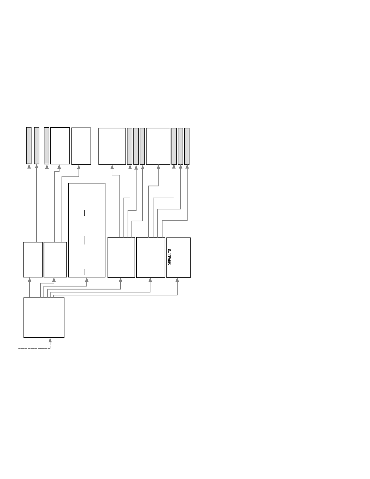
60 / 60 le00100a0600p_05 BKI 11 ATEX 0012 X
------------------ -----------------
SECURITY
---------------- -----------------
USER LOCK
SERVICE LOCK
USER LOCK
SERVICE LOCK
OUTPUT TEST
---------------- -----------------
ANALOG OUTPUT
RELAY OUTPUT
SERIAL OUTPUT
SERIAL OUTPUT
---------------- -----------------
1200Hz
2200Hz
CURRENT VALUE
SENSOR SETUP CALIBRATION /
VIEW/EDIT TABLE
ADD ITEM
DELETE ITEM
RESET TO DEFAULT
RESET TIMER
pH/OR P/DO SIMULATION
-------------- -------------------
MODE
TIME
BOTTOM VAL UE
UPPER VALUE
MODE
------------ ---------------------
OFF
MANUAL VALUE
TRIANGLE WAVE
SQUARE WAVE
TIME
BOTTOM VALUE
UPPER VALUE
------------------ ---------------
LOAD DEFAULT
CLEAR TIMERS
-------------- -------------------
TEMP. SIMULATION
MODE
TIME
BOTTOM VALUE
UPPER VALUE
MODE
---------------- -----------------
OFF
MANUAL VALUE
TRIANGLE WAVE
TIME
BOTTOM VALUE
UPPER VALUE
SERVICE
SECURITY
OUTPUT TEST
SENSOR CALIBRATION
pH/O RP/DO SIMU LATION
TEMP. SIMULATION
DEFAULTS
RESTART
pH:
SET ZERO POINT
ORP:
ZERO CAL. IN LIQUID
SPAN CAL. IN AIR
SPAN C AL. IN LIQUID
RESET TO DEFAULT
RESET TIMER
DO:
RELAY OUTPUT
------------- --------------------
DEENER GISED
ENERGISED
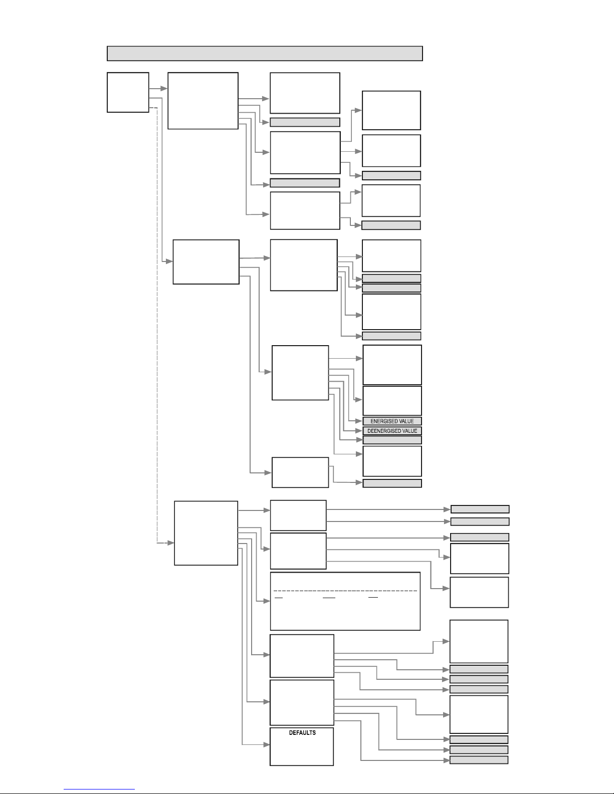
le00100a0600p_05 Menumap
BASIC SETUP
----------------------------------MEASURING UNIT(DO)
DAMPING TIME.
TEMP. COMPEN SATION
SALINITY CORRECTION(DO)
PRESSURE CORRECTION(DO)
DAMPING TIME
MEASURING UNIT
-------------------------------ppm
mg/l
%sat
MODE
--------------------------------AUTO
MANUAL
OFF
UNIT
---------------------------------
C°
F
°
MANUAL VALUE
MAIN MENU
---------------------BASIC SETUP
OUTPUT SETUP
SERVICE
OUTPUT SETUP
----------------------------------ANALOG OUTPUT
RELAY OUTPUT
SERIAL OUTPUT
ANALOG OUTPUT
--------------------------------CURRENT MODE
4 mA VALUE
20 mA VALUE
ERROR MODE
MANUAL VALUE
CURRENT MO DE
--------------------------------AUTO
MANUAL
4 mA VALUE
ERROR MODE
--------------------------------HOLD
3.8 mA
22 mA
MANUAL VALUE
ADDRESS
SERIAL OUTPUT
--------------------------------ADDRESS
RELAY OUTPUT
---------------------------------
FUNCTION
--------------------------------HYSTERESIS
WINDOW
DELAY TIME
MODE
---------------------------------
OFF
pH/ORP/DO
TEMP
ON ERROR
INVERTING
---------------------------------
NO
YES
20mA VALUE
MODE
FUNCTION
4 mA VALUE
20 mA VALUE
DELAY TIME
INVERTING
--------------------- --------------
SECURITY
--------------------- ------------
USER LOCK
SERVICE LOCK
USER LOCK
SERVICE LOCK
OUTPUT TEST
(
KIMENETI TESZT)
--------------------- ------------
ANALOG OUTPUT
RELAY OUTPUT
SERIAL OUTPUT
SERIAL OUTPUT
--------------------- ------------
1200Hz
2200Hz
CURRENT VALUE
SENSOR SETUP CALIBRATION /
VIEW/EDIT TABLE
ADD ITEM
DELETE ITEM
RESET TO DEFAULT
RESET TIMER
pH/ORP/DO SIMULATION
--------------------- ------------
MODE
TIME
BOTTOM VALUE
UPPER VALUE
MODE
--------------------- ------------
OFF
MANUAL VALUE
TRIANGLE WAVE
SQUARE WAVE
TIME
BOTTOM VALUE
UPPER VALUE
--------------------- ------------
LOAD DEFAULT
CLEAR TIMERS
--------------------- ------------
TEMP. SIMULATION
MODE
TIME
BOTTOM VALUE
UPPER VALUE
MODE
--------------------- ------------
OFF
MANUAL VALUE
TRIANGLE WAVE
TIME
BOTTOM VALUE
UPPER VALUE
SERVICE
SECURITY
OUTPUT TEST
SENSOR CALIBRATION
pH/ORP/DO SIMULATION
TEMP. SIMULATION
DEFAULTS
RESTART
pH:
SET ZERO POINT
ORP:
ZERO CAL. IN LIQUID
SPAN CAL. IN AIR
SPAN CAL. IN LI QUID
RESET TO DEFAULT
RESET TIMER
DO:
PRESSURE CORRECTION
-------------------------------UNIT
MANUA L VALUE
UNIT
--------------------------------C°
F°
MANUAL VALUE
MANUAL VALUE
TEMP. COMPENSATION
-------------------------------MODE
UNIT
MANUAL VALUE
RELAY OUTPUT
--------------------- ------------
DEENERGISED
ENERGISED
6. MEN8UMAP
 Loading...