

Page 1
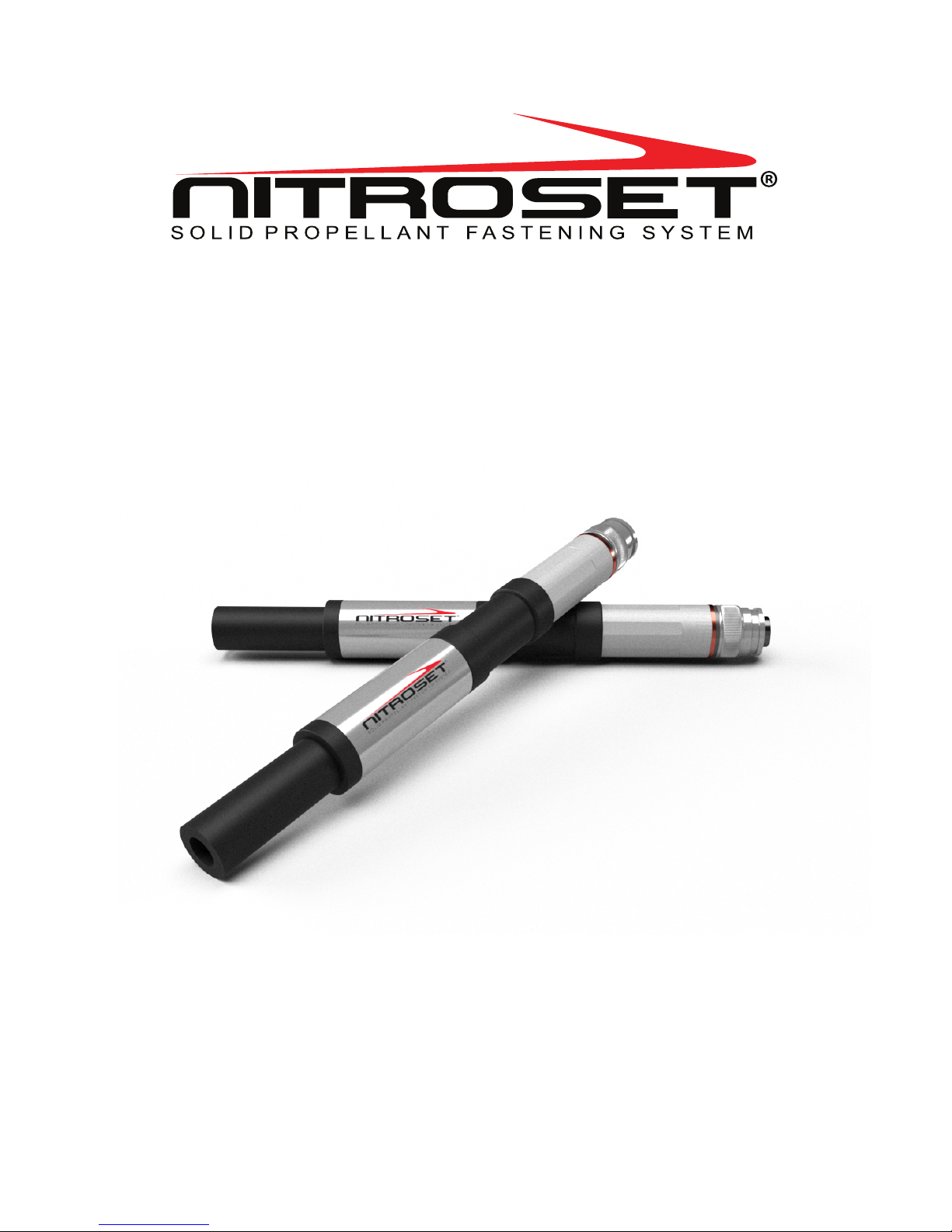
NTS8X Tool Operation
& Safety Manual
VER 18.8
US Patent: US8397969B2
Additional Patents Pending
Page 2

Table of Contents
Warnings and Safety Precautions
Basic Instructions
Required Safety & Protective Equipment
Misuse of the Tool
General Safety Precautions
Spall Guard Usage Instructions
Worksite Preparation
Acceptable Base Materials
Inappropriate Base Materials
Check Before Fastening
NTS8X Universal Nosepiece
Adapter Usage Table
Operating Instructions
Loading and Actuating Instructions
Using NITROSET® Tool with a NITROSET® Pole
DOs and DON’Ts
DOs
DO NOTs
Troubleshooting Guide
Changing the Firing Pin
Tool Disassembly
Tool Assembly
Cleaning Procedure
NITROSET® Tool Full Cleaning Procedure
Interim Cleaning Procedure
Parts List & Diagram
Parts List
Parts Diagram
3
3
3
4
4
5
5
5
6
7, 8
8
9
10
11, 12
13
14
15
16
16
17
18
Page 3

DO NOT OPERATE THE NITROSET TOOL
UNLESS YOU HAVE COMPLETELY READ
AND UNDERSTOOD THE OPERATION
AND SAFETY MANUAL
WARNING
Training is required for use of this tool.*
*Please contact your local distributor or visit www.nitroset.com for more information.
Page 4
You are required to understand and follow all safety instructions for proper and
safe use of NITROSET® tools. If you require any assistance, please contact your
jobsite safety foreman or call Nitroset, LLC. at 1.800.524.4649.
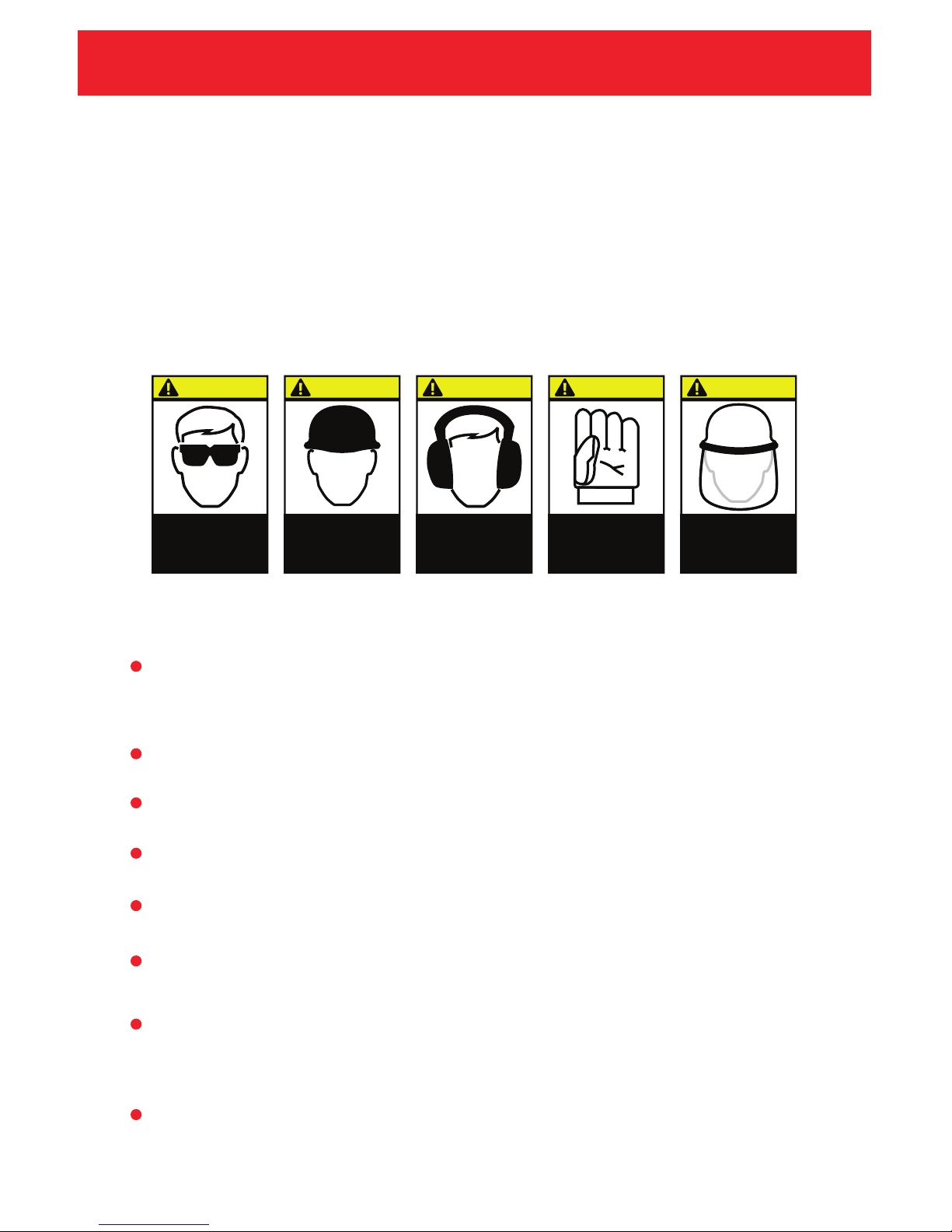
Always wear proper safety equipment including safety glasses, hard hats,
hearing protection, and gloves while operating the tool.
Manipulation or modification of the tool is not permitted. Any alteration of the
tool or use of non-genuine NITROSET® parts might impair function or cause
damage to the tool. Use of non-genuine parts will void any warranties.
Do not operate in an explosive or inflammable environment.
Never put your hand over the nosepiece of the tool.
Never point the tool at yourself or any bystanders.
Never press the nosepiece against any part of your body or anyone else’s body.
Only fasten into appropriate substrates. Use of inappropriate substrates may
cause injuries.
Never attempt to disassemble, modify or alter the fastener assemblies. Use only
the required length and type of pin (with correct adapter) for the application
(Refer to the Adapter Usage Table on Page 6).
Use only genuine NITROSET® Fasteners with the NITROSET® system. Use of
incorrect fasteners might lead to injury o
r damage to the tool.
Required Safety & Protective Equipment
Basic Instructions*
Safety Precautions
WWW.NITROSET.COM
Misuse of the Tool
*According to ANSI A10.3 and DOT (ref: EX2009040168) NITROSET® tools are not classified as a powder
actuated tool, thus no licensing is required.
3
CAUTION
Face shield
(recommended)
CAUTION
Wear hard
hats
CAUTION
Wear hearing
protection
CAUTION
Wear safety
gloves
CAUTION
Wear safety
glasses
Page 5
WWW.NITROSET.COM
Safety Precautions
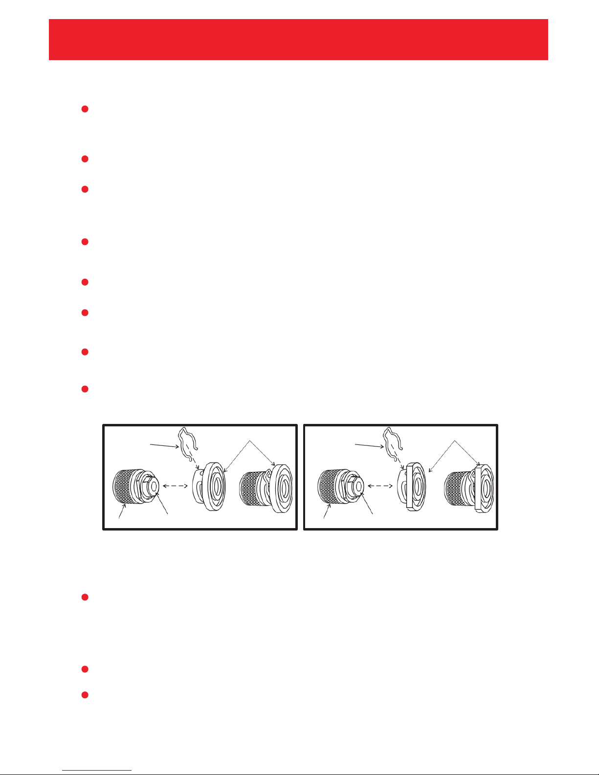
Install appropriate spall guard to nosepiece.
Ensure spall guard is installed flush.
Install the spall guard clip to the nosepiece to hold spall guard in place.
Round Spall Guard - Use with Pins & Pins with Washers
Spall Guard with Cut - Use with Fastener Assemblies with Clips
General Safety Precautions
Round Spall Guard Spall Guard with Cut
For Pins & Pins with Washers
Spall Guard Usage Instructions
For Clip Assemblies
SPALL
GUARD
CLIP
ROUND SPALL GUARD
SPALL
GUARD
CLIP
SPALL GUA RD W ITH
CUT
DEBRIS
CUP
MUZZLE
DEBRIS
CUP
MUZZLE
b
a
4
Inspect the tool to ensure that the tool is complete, undamaged, and all parts
are secure prior to use. Damaged parts should be replaced using genuine
NITROSET® parts.
Insert the fastener assembly completely into the muzzle to ensure the
correct function of the tool. Fasteners that do not completely insert into the
muzzle should not be used and should be disposed of appropriately.
Never leave a loaded tool unattended. Only load the tool prior to fastening.
The NITROSET® tool should be reset after every actuation to clear any debris
from the nosepiece (muzzle+debris cup) of the tool.
The trigger body and reset sleeve should be held in place when loading a fastener.
Always remove fasteners and any debris from the muzzle prior to cleaning,
servicing, maintenance, or storage of the tool.
Always hold the tool securely and perpendicular to the working surface when
making a fastening.
Use the NITROSET® round or cut spall guard with clip to prevent concrete spall.
Page 6

The NITROSET® tool is NOT for fastening into the following base materials:
Wood
Drywall
Glass
Tile
Rock
These materials may shatter causing the fastener or base substrate to
fly free and might cause serious injury to the operator or bystanders.
WWW.NITROSET.COM
Worksite Preparation
The NITROSET® tool is for fastening into the following base materials only:
Concrete
Structural Steel
Check the thickness and type of base material before fastening, following
your specific jobsite instructions and building code requirements.
In fastening into steel substrate, the minimum thickness of substrate must
be 3/16".
Minimum concrete thickness is three times the fastener penetration
(ie. 3" of concrete base material is a minimum for a 1" penetration).
Never attempt to fasten into any other materials other than those listed above.
Acceptable Base Materials
Inappropriate Base Materials
Check Before Fastening
5
Page 7
WWW.NITROSET.COM
NTS8X Universal Nosepiece
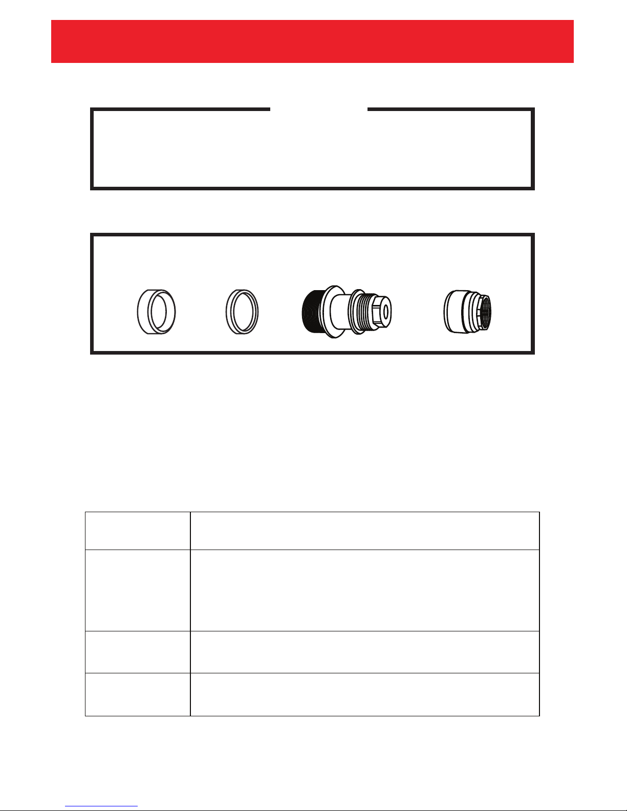
The universal nosepiece with two different adapters (NTS101-1S-C3-C) will be used
for different length pin or clip assemblies.
Note: Adapter is placed between the muzzle and the reset sleeve.
Adapter Usage Table
6
Adapter
Requirement
No Adapter
Needed
With A-Adapter
(Red)
With B-Adapter
(Blue)
Types of Pin and Pin/Clip Assembly
CLAS532, CLSUPL532, PIN532NW, STT14*
CLAS525, CLSUPL525, CLRHD14-525, PIN222, PIS525W
*Use NTS101-1-ST Nosepiece with A-Adapter (Red) for STT14.
A-Adapter B-Adapter Muzzle Debris Cup
NTS101-1S-C3-C
CLU222,
CLS222S,
CLR14-222,
CLR38-222,
CLT219,
CLC38-222,
CLC12-222,
CLC34-222,
CLC1E-222,
CLR14222-BRT114
PIN219,
PIN219T,
PIN222W,
PIN222SW,
PIN319,
PIK313,
PIK316,
PIS222W
REMEMBER
Always use correct adapter for different types of pin and pin/clip assembly.
Please refer to Adapter Usage Table below.
Page 8
WWW.NITROSET.COM
Operating Instructions
1. Reset the tool before each fastening to ensure the muzzle barrel is clear
of any debris.
2. Insert the fastener fully into the muzzle of the tool. Fasteners must be fully
seated in muzzle to ensure proper actuation.
(Hold reset sleeve before inserting fasteners)
3. Place the NITROSET® tool perpendicular against the fastening surface.
A) Pull back on front of muzzle until reset spring fully collapses.
B) Ensure firing pin guide clears all debris from muzzle chamber
prior to inserting new fastener assembly.
In case of jammed fasteners – Refer to the Troubleshooting Guide (Page 11) for
proper removal of all jammed fasteners.
Loading and Actuating Instructions
7
If the fastener assembly cannot be inserted into the muzzle, do not force the
fastener into the muzzle. This can jam the fastener in the tool and damage
the fastener. Fasteners that cannot be inserted should be removed and
discarded appropriately.
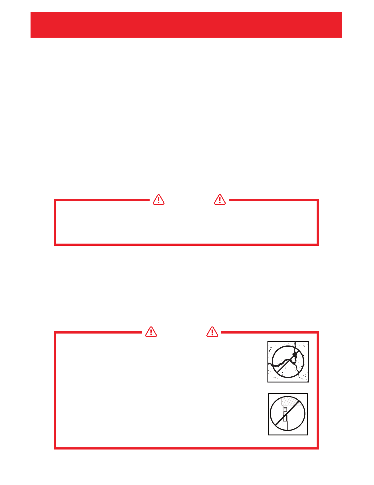
WARNING
Fasteners should not be driven close to the edge of the base
substrate.
Always maintain a distance of at least 3" from the concrete
edge or 1" from the steel edge.
Too close to edge
WARNING
Cracked concrete may cause loud noise when using the tool.
Page 9
WWW.NITROSET.COM
Operating Instructions
4. Position the tool and push directly to feel the engagement of the firing
spring. Follow with a smooth and forceful motion to compress the firing
spring to trigger the firing mechanism. This is the correct fastening
procedure to minimize spalling and noise.
5. Reset the tool to ensure the muzzle barrel is clear of debris and repeat
from Step 1 to 4.
If the tool fails to fasten, remove the spent fastener assembly while pointing
the tool away from yourself and any bystanders.
The use of NITROSET® pole is recommended for maximum eciency on ceiling
fastening applications. The end of the wire assembly should be placed inside the
pole for better control. Actuate by following the actuating instructions as detailed.
Using NITROSET® Tool with a NITROSET® Pole
8
When using an electrically conductive or metallic pole, be sure to maintain a
minimum 10 ft clearance from all electrical lines to avoid electrical hazard.
WARNING
After the tool has been in use, the muzzle and other parts may be hot.
Always wear gloves to handle these areas.
WARNING
IMPORTANT: DO NOT BOUNCE FIRE THE TOOL!
Page 10

WWW.NITROSET.COM
DOs and DON’Ts
DO read and understand the correct and safe usage instructions for the
NITROSET® Fastening System.
DO recognize that operator and bystander safety is the most important factor
when considering a NITROSET® tool application.
DO wear safety goggles and other suitable personal protective items while
using NITROSET® tool.
DO ensure all individuals working in the same area as those using the
NITROSET® system also are wearing proper safety equipment.
DO make sure when fastening into concrete, the base material thickness is at
least 3 times the shank penetration.
DO make sure when fastening into steel substrate, the minimum thickness of
the substrate must be 3/16".
DO use correct adapter for different types of pin and pin/clip assembly.
DO make sure that the tool is firmly flat to the surface before fastening.
DO reset the tool pointed away from yourself and any bystanders and eject any
debris from muzzle piece before inserting the fastener into the barrel.
DO remove defective tools, parts and/or accessories from service immediately.
DO only use the correct tools to disassemble the NITROSET® Tool. Use of pipe
wrenches or vise grips can damage the tool.
DO only use genuine NITROSET® repair parts. Any parts from dierent
manufacturers might impair function or cause damage to the tool and lead to
injury.
DO clean the tool daily and empty the debris cup every 500 fastenings or as
needed.
DOs
9
Page 11

WWW.NITROSET.COM
DOs and DON’Ts
DO NOT use NITROSET® tools to fasten into brittle materials such as brick, tile,
rock or glazed material.
DO NOT attempt to drive fasteners into soft materials such as wood or drywall
or light gauge metal.
DO NOT attempt to drive fasteners into hardened steel, cast iron, or natural rock
such as marble.
DO NOT drive fasteners into base steel thinner than the shank diameter of the
fastener.
DO NOT fasten into cracked or spalled areas of concrete.
DO NOT drive fasteners closer than 3" to the edge of the concrete materials and
1" to the edge of steel base materials.
DO NOT use NITROSET® tools in a hazardous environment.
DO NOT use the tool prior to ensuring that all parts are in good working order
and securely attached to the tool. All parts should be fully threaded and hand
tight.
DO NOT place hand over the muzzle end to reset the tool.
DO NOTs
10
Page 12
WWW.NITROSET.COM
Troubleshooting Guide
A) If cycling the tool does not clear the jammed fastener, remove the
nosepiece completely. The jammed fastener can then be removed
from the other end.
B) DO NOT strike the tool against the substrate to dislodge the fastener.
C) If the fastener remains permanently jammed, please contact the
appropriate support personnel.
A) Check if you are fastening to the appropriate substrate material.
B) Check the nosepiece is free of debris and reset the tool.
C) Check if the correct adapter is being used (Refer to Adapter Usage
Table on Page 6).
D) Ensure the tool is assembled properly according to the manual and
instructions.
E) Before firing, make sure the nosepiece is perpendicular (right angle) to
the material surface. The tool is not designed to fasten at other angles.
F) Check if the firing pin is piercing the NITROSET pill. If it's piercing the
pill and not firing, then check for damage to the firing pin. Replace
firing pin if damaged.
G) If the tool still does not actuate after checking all the above, follow the
instructions (Page 14) and disassemble to check for broken parts.
11
I. The fastener is jammed inside the nosepiece.
II. The tool does not fire.
Lorem Lorem ipsum dolor sit
amet, consectetuer adipiscing
elit, sed diam nonummy nibh
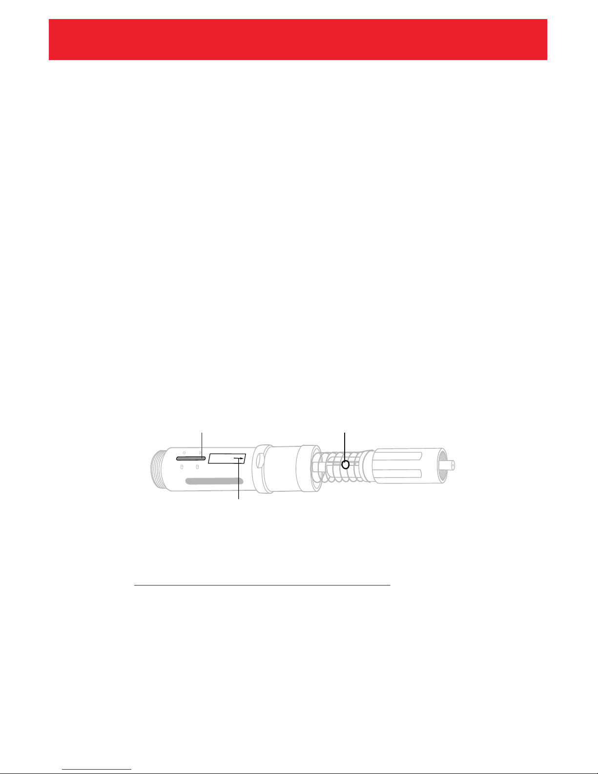
Make sure the trigger key is in line with the trigger ball release
The guiding arrow may wear out, use the trigger key
as a guide in such occurrence
Page 13

WWW.NITROSET.COM
Troubleshooting Guide
A) Check if you are fastening to the appropriate substrate material.
B) Check if the correct adapter is being used.
C) Before firing, make sure the nosepiece is perpendicular to the material
surface. The tool is not designed to fasten at other angles.
D) Check and clean the debris cup. Ensure the vents in the debris cup are
clear of debris.
E) Ensure the debris cup and muzzle are securely fastened to the tool.
A) Ensure the tool is assembled properly according to the manual and
instructions.
B) Clean and lubricate according to the operator's manual.
C) Check that the springs are clean and straight.
A) Disassemble the tool and check to see if the buer is in place. This part
acts as a shock absorber. Damage to the tool is possible if used without
the buer properly inserted.
B) Clean to the tool to ensure no debris has gotten into the main body of
the tool.
If all of the above fails, please contact your local supplier's technical support
personnel to address the issues or visit our website at:
12
III. The tool fires loudly.
IV. The tool is dicult to depress and fire.
V. Firing Pin Holder and Guide are damaged.
REMEMBER
WWW.NITROSET.COM
Page 14
WWW.NITROSET.COM
Changing the Firing Pin
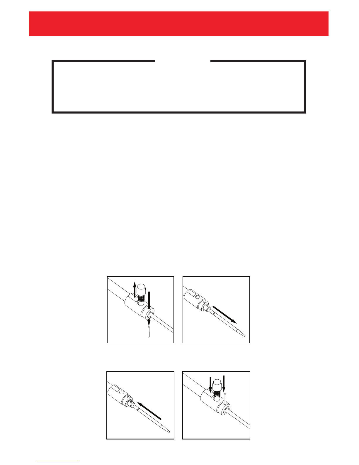
1. Use the provided roll pin punch to knock out the 1/8" roll pin.
2. Remove the worn firing pin from the firing pin holder
3. Seat a new 1/8" roll pin into the holder. Do not insert the roll pin completely.
4. Insert a new firing pin into the slot in the firing pin holder. Ensure that the
holes on the back of the firing pin line with the holes in front of the holder.
5. Using a hammer, fully insert the 1/8" roll pin.
6. Reinstall the trigger spring and trigger ball release into the appropriate slot
on the firing pin holder.
7. While depressing the trigger ball spring, insert the firing assembly into the
firing pin guide.
When removing the firing pin, depress the trigger ball release, and guide the
pin out.
Keep the trigger ball release depressed until the pin exits the guide, otherwise
the spring will propel the trigger ball away.
13
REMEMBER
Assembly
Disassembly
Page 15
WWW.NITROSET.COM
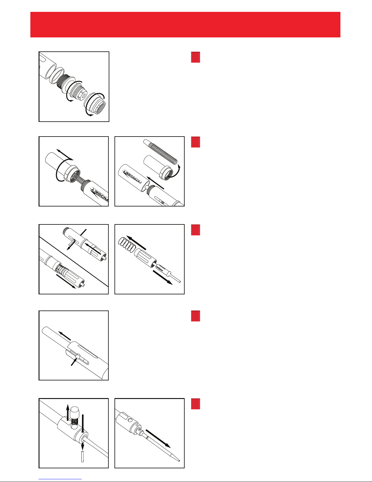
Tool Disassembly
2
2
1
1
1
2
Remove Debris Cup from the Muzzle.
Remove Muzzle from the Reset Sleeve.
Use the included wrenches for
assistance as necessary.
Slide the Adapter off the threads of the
Muzzle as necessary.
Remove the End Cap from the tool.
Slide the Firing Spring off the tool. Note
the Buffer is attached to the end of the
Firing Spring. Check condition of Firing
Spring and Buffer.
Slide off the Outer Cover Sleeve.
Depress the Reset Spring to collapse
the Reset Sleeve. This will loosen the
Main Assembly Pin and allow it to be
removed from the tool.
Slide the Main Firing Assembly from
the main body of the tool.
Depress the Trigger Ball Release to
compress the Trigger Ball Spring and
slide the Firing Pin Assembly from the
Firing Pin Guide.
Keep pressure over the Trigger Ball to
hold it in place while removing the
assembly. Releasing the Trigger Ball
may cause it to spring up.
Once the Firing Pin Assembly has been
removed from the Guide, slowly
release the Trigger Ball and remove it
from the Firing Pin Holder.
To remove the Firing Pin, use the
provided firing pin punch and knock
out the 1/8" Roll Pin.
14
Page 16
WWW.NITROSET.COM
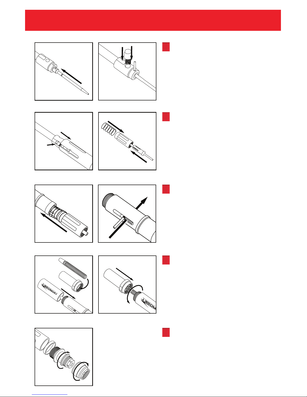
Assemble Firing Pin into Firing Pin
Holder using the 1/8" Roll Pin.
Insert Trigger Ball Spring into Trigger
Ball Release and place into the Firing
Pin Holder.
Slide complete Firing Assembly into
the Guide while depressing the
Trigger Ball Release until it clicks into
the Guide.
Insert Guide and Holder through the
Reset Sleeve. Attach Reset Spring to
Reset Sleeve.
Insert Reset Sleeve into the Trigger
Body. Make sure the trigger key on
the body aligns properly with the
Trigger Ball Release.
Insert Main Assembly Pin. Ensure
coils of the Reset Sleeve are all above
the pin.
Slide Outer Cover Sleeve over the
Trigger Body.
Insert the Firing Spring with the Buffer
attached over the Holder.
Attach the End Cap of the tool.
Secure the Debris Cup to the Muzzle.
Slide appropriate Adapter onto the
Nosepiece.
Secure the complete Nosepiece
Assembly onto the Reset Sleeve.
Tool Assembly 15
2
1
Page 17

WWW.NITROSET.COM
Cleaning Procedure 16
1. It is recommended that the NITROSET® tool be cleaned every day after use.
Proper maintenance and cleaning of the tool enables the tool to operate at
peak performance.
2. First, be sure all fastener assemblies and debris are ejected from the tool by
resetting it pointed away from yourself or any bystanders.
3. Remove the muzzle by unscrewing it from the tool shank. Then, remove the
end cap and disassemble the entire tool following the tool disassembly
instructions (Page 14).
4. Empty the debris cup.
5. To clean, you should use diluted industrial cleaner and degreaser similar to
Strike-Hold or other similar non-oil base degreaser to spray or wipe the tool
surface. Allow contact time of 3 to 5 minutes before scrubbing. Rinse with
water and wipe it dry with towel or paper.
6. Re-assemble the tool (Page 15).
NITROSET® Tool Full Cleaning Procedure
1. Empty the debris cup after every 500 fastenings, or as needed to optimize
performance.
2. A liquid shot of degreaser lubricant at approximately every 500 to 1000
fastenings is recommended to maintain a smooth operation.
3. This will help tool performance and actuating consistency, making your
end-of-day cleaning easier.
Interim Cleaning Procedure
Page 18
WWW.NITROSET.COM
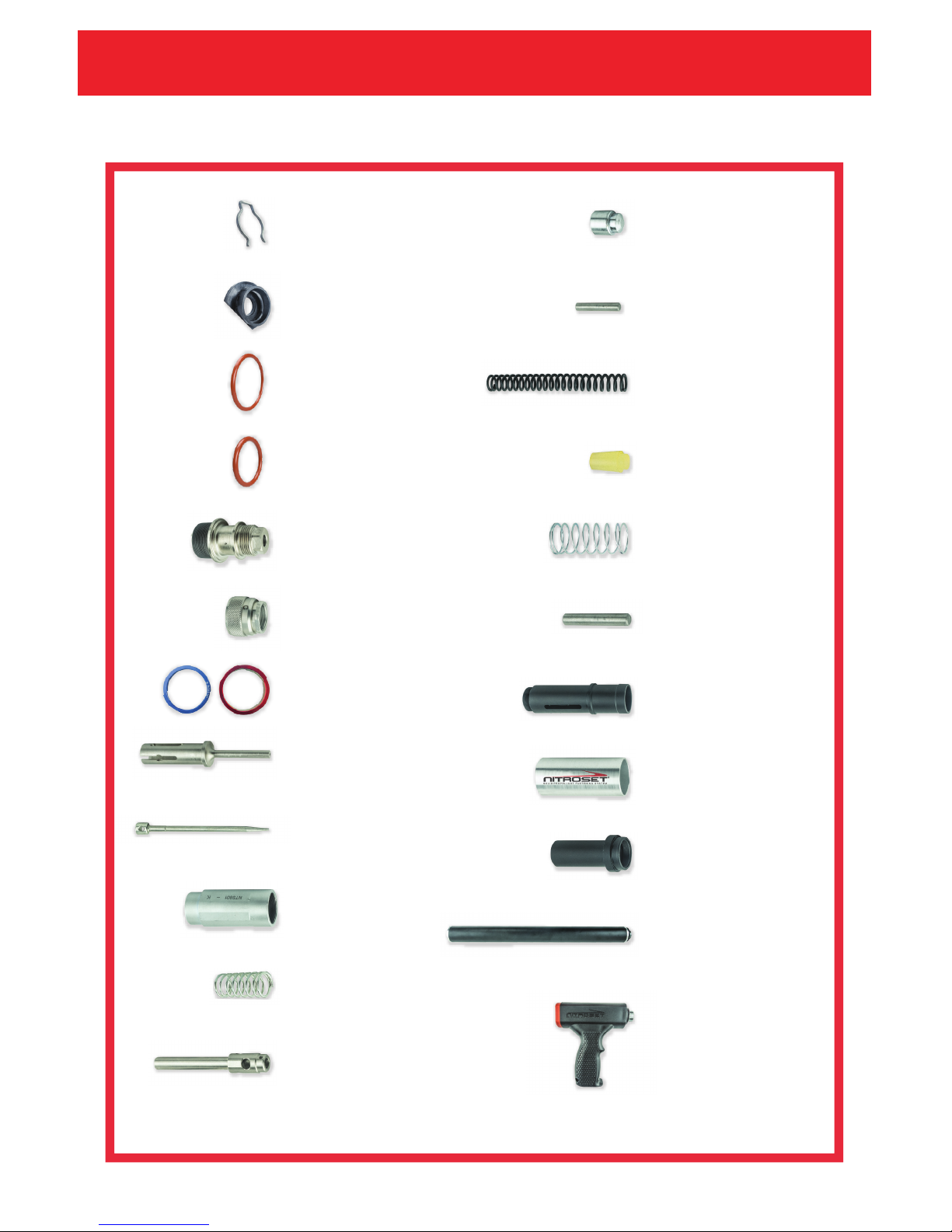
Parts List 17
1/8" Roll Pin
NTS1018
Trigger Ball Release
NTS1017
Nosepiece Rubber Gasket
NTS10129
Spall Guard*
NTS1010C
Firing Pin
NTS1014
Firing Pin Holder
NTS1016
Trigger Ball Spring
NTS1015
Firing Pin Guide
NTS5X3
Firing Spring
NTS1019SOTCS
Spall Guard Clip*
NTS1010U
Debris Cup
NTS1012C
Muzzle
NTS101C3
Debris Cup Rubber Gasket
NTS10130
Outer Cover Sleeve
NTS5X14
End Cap
NTS5X15
Buffer
NTS10116
Triple Play Extension*
NTS10118
Reset Spring
NTS5X11
Reset Sleeve
NTS8X10
1/4" Main Assembly Pin
NTS5X12
Trigger Body
NTS5X13
Hand Grip*
NTS10119
* These parts are included in the tool kit.
Blue/Red Adapter*
NTS10117
Page 19
WWW.NITROSET.COM
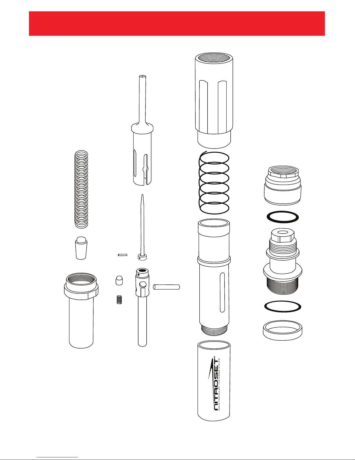
Parts Diagram 18
NTS5X3
NTS1017
NTS1015
NTS5X12
NTS1018
NTS1014
NTS1016
NTS10116
NTS1019SOTCS
NTS5X15
NTS5X10
NTS5X11
NTS5X13
NTS5X14
NTS1012C
NTS101C3
NTS10130
NTS10129
NTS10117
* Parts in this diagram are to scale.
Page 20

5600 Bonhomme Rd., Ste. D
Houston, TX 77036
Tel: 1.800.524.4649 Fax: 713.781.5677
www.nitroset.com
Nitroset One-Year Limited Warranty
• Nitroset, LLC. offers a one-year limited warranty on the Nitroset
Fastening Tools against manufacturing defect from the date
of purchase.
• The manufacturing defect warranty covers performance
issues of the covered parts.
• Excluded are normal wear and tear parts, improper
maintenance, improperly handling, alteration, abuse, neglect,
accident, vandalism, theft, fire, water, or damage because of
other peril or natural disaster.
• The determination if the tool is covered by defect warranty is
at the sole discretion of Nitroset, LLC. We reserve the right to
repair or replace the item with like and kind products.
• The product owner is responsible for inbound shipping costs.
Excluded from all warranties are inbound freight and postage
or freight losses.
• Damage resulting from the installation or use of any part,
accessory, or attachment not approved by Nitroset, LLC for
use with the products(s) will void the warranty as to any
resulting damage.
• The warranty is non-transferable and limited exclusively to the
original purchaser.
All warranty returns for repair must include a Return Merchandise Authorization (RMA) number
obtained from a Nitroset representative. The claim product must be sent at customer’s
expense to Nitroset, LLC. for evaluation. Unauthorized returns without RMA will not be accepted.
 Loading...