

Page 1
1
Nitronic
NitronicNitronic
Nitronic
AG
AGAG
AG
Mattenstrasse 11
Switzerland
Fax +41 32 373 70 75
Sdasdasdsdfdsdcdscsdcdcd
CH – 2555 Brügg Tel. +41 32 373 70 70
cdcsc
Operating
Operating IIIInstructions
OperatingOperating
Strip
Strippi
StripStrip
ping machine
ng machine ST215
pipi
ng machine ng machine
nstructions
nstructionsnstructions
ST215 //// ST215W
ST215ST215
ST215W
ST215WST215W
V2.1 (based on V2.1 German)
Please read through these Operating Instructions carefully before starting work.
Page 2

2
Nitronic
NitronicNitronic
Nitronic
AG
AGAG
AG
Mattenstrasse 11
Switzerland
Fax +41 32 373 70 75
Sdasdasdsdfdsdcdscsdcdcd
CH – 2555 Brügg Tel. +41 32 373 70 70
cdcsc
General
General
GeneralGeneral
We thank you for your confidence in our company and that you have decided upon our centering device.
To be able to achieve the optimum performance please read these Operating Instructions with due care and attention.
In the event of damage caused by not following these instructions any guarantee claims will be null and void. We will
also not accept any liability for consequential damages.
Table of
Table of Contents
Table of Table of
Table of
Table of Contents
Table of Table of
Symbols
Symbols ............................................................................................................................................................. 3
SymbolsSymbols
Product description
Product description .......................................................................................................................................... 3
Product descriptionProduct description
Centering device (Optional)
Centering device (Optional) ............................................................................................................................. 3
Centering device (Optional)Centering device (Optional)
Connecting
Connecting the
ConnectingConnecting
Control Elements
Control Elements ............................................................................................................................................... 4
Control ElementsControl Elements
Placing
Placing in
Placing Placing
Setting the
Setting the centering
Setting the Setting the
Setting the Diameter
Setting the Diameter ..................................................................................................................................... 5
Setting the DiameterSetting the Diameter
Setting the Wayback (ST215W only)
Setting the Wayback (ST215W only) ........................................................................................................... 6
Setting the Wayback (ST215W only)Setting the Wayback (ST215W only)
SSSSetting
Setting the rotation duration / incision rate
Setting the rotation duration / incision rate ............................................................................................... 7
Setting the rotation duration / incision rateSetting the rotation duration / incision rate
Counterclockwise or clockwise rotation / no rotation
Counterclockwise or clockwise rotation / no rotation .............................................................................. 7
Counterclockwise or clockwise rotation / no rotationCounterclockwise or clockwise rotation / no rotation
Maintenance
Maintenance ..................................................................................................................................................... 9
MaintenanceMaintenance
Lubrication
Lubrication..................................................................................................................................................... 9
LubricationLubrication
Cleaning
Cleaning ......................................................................................................................................................... 9
CleaningCleaning
Changing the stripping blades
Changing the stripping blades ..................................................................................................................... 9
Changing the stripping bladesChanging the stripping blades
Dismantling
Dismantling the
DismantlingDismantling
Assembling
Assembling the
Assembling Assembling
Fit the stripping blades and calibrating the centering unit
Fit the stripping blades and calibrating the centering unit ..................................................................... 13
Fit the stripping blades and calibrating the centering unitFit the stripping blades and calibrating the centering unit
Error
Error sources
Error Error
Faults
Faults on
FaultsFaults
Basic Equipment, Spare Parts, Options
Basic Equipment, Spare Parts, Options ........................................................................................................ 16
Basic Equipment, Spare Parts, OptionsBasic Equipment, Spare Parts, Options
Basic Equipment ST215
Basic Equipment ST215 .............................................................................................................................. 16
Basic Equipment ST215Basic Equipment ST215
Spare Parts
Spare Parts .................................................................................................................................................. 16
Spare PartsSpare Parts
Options
Options ......................................................................................................................................................... 17
OptionsOptions
Technical
Technical Data
TechnicalTechnical
Contents
ContentsContents
Contents .............................................................................................................................................. 2
ContentsContents
the machine
machine .................................................................................................................................. 4
thethe
machinemachine
in operation
operation .......................................................................................................................................... 5
in in
operationoperation
centering devic
centering centering
etting the
ettingetting
the LLLLength
ength ......................................................................................................................................... 6
thethe
engthength
the centering
thethe
the centering
thethe
sources ................................................................................................................................................... 14
sourcessources
on cable
cable ............................................................................................................................................ 14
on on
cablecable
Data ................................................................................................................................................ 17
DataData
device
e ........................................................................................................................ 5
devicdevic
ee
centering unit
centering centering
centering dev
centering centering
unit .................................................................................................................. 11
unitunit
device
devdev
ice .............................................................................................................. 12
iceice
Page 3
3
Nitronic
NitronicNitronic
Nitronic
AG
AGAG
AG
Mattenstrasse 11
Switzerland
Fax +41 32 373 70 75
Sdasdasdsdfdsdcdscsdcdcd
CH – 2555 Brügg Tel. +41 32 373 70 70
cdcsc
Symbol
Symbolssss
SymbolSymbol
Please adhere strictly to the work practices and procedures indicated by this pictogram. Non-adherence could
cause damage to the tool or the cable.
This pictogram serves to illustrate the working and operating procedures which must be adhered to, as well as to
give important information about how the tool works.
Product description
Product description
Product descriptionProduct description
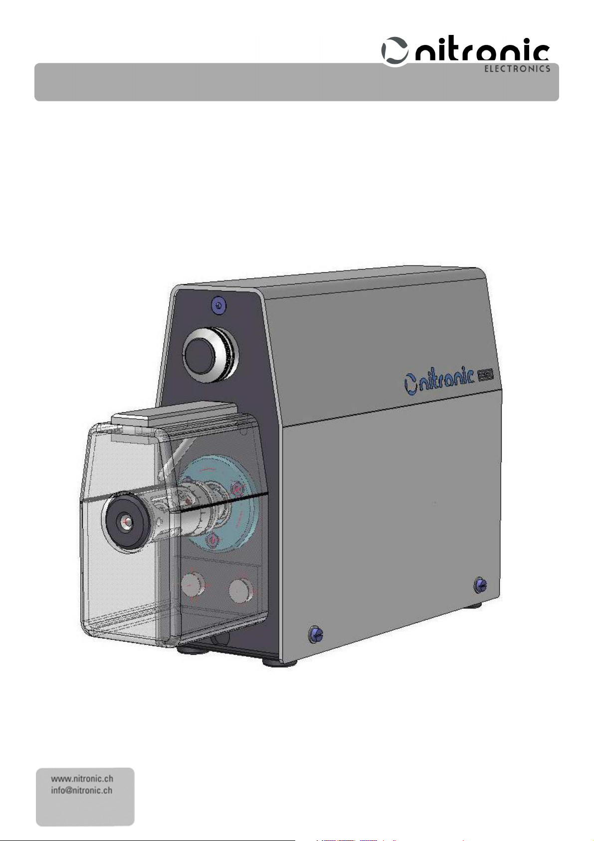
The ST215 is a high precision stripping and twisting machine specially developed for stripping small diameter cables.
High quality machining together with high grade materials render the ST215 a robust production machine.
The ST215 is a true all-rounder; it masters the stripping of standard cables in short cycles also micro-coaxial cables
with the highest precision. The absence of gripper jaws enables the ST215 to process the shortest of cable ends,
crushing of the sheath being also ruled out. The patented 4444----blade
blade system
system permits the stripping of cable ends with total
bladeblade
systemsystem
and repeatable accuracy.
The sheath is removed by a rotary incision with subsequent pulling-off in a single operation. The ST215 can be
steplessly set to a different diameter or length in seconds by means of a scale.
System overview:
• Rotary incision
• Stripping head with a 4 blade system in one plane
• Knife changing performed without tools
• Stepless setting of diameter and length by means of a scale
The ST215 is intended exclusively for stripping copper conductors. Take care to ensure that no metal objects
(e.g. screwdrivers, tweezers) come into contact with the blades where they can cause damage.
Centering d
Centering device (Optional)
Centering dCentering d
The purpose of the steplessly adjustable centering is to ensure that the cable is aligned accurately with the centre of
the blades. If your ST215 has been delivered without a centering device, this can be retrofitted without problems.
The advantages of the centering device are as follows:
• Influencing of the stripping quality by the user is practically ruled out.
• The stripping diameter can be set very close to the conductor, enabling very thin walled insulations to be stripped
without problem.
evice (Optional)
evice (Optional)evice (Optional)
Page 4
4
Nitronic
NitronicNitronic
Nitronic
AG
AGAG
AG
Mattenstrasse 11
Switzerland
Fax +41 32 373 70 75
5
30
31
Sdasdasdsdfdsdcdscsdcdcd
CH – 2555 Brügg Tel. +41 32 373 70 70
cdcsc
Connecting
Connecting the
ConnectingConnecting
the machine
machine
thethe
machinemachine
• Connect the machine to the voltage supply and the connection marked „24V DC
24V DC“ with the mains power unit. If the
24V DC24V DC
mains connector plug is not compatible with your mains supply socket, please contact your Nitronic supplier or us
directly.
• Connect the machine to your compressed air supply system. The supplied compressed air hose is fitted with a
coupling on the machine side, the other side is free. You must fit a coupling to this free side which is compatible
with your compressed air system. The outer hose diameter is 6 mm.
The machine is equipped with an internal pressure controller; however the incoming pressure must be between
5 and 8 bar. The pressure is in no case to exceed 8 bar!
• Connect the foot pedal switch (optional) to the connection „Foot Pedal
Foot Pedal“.
Foot PedalFoot Pedal
With the foot pedal connected, the activation sensor is inactive! The machine can only be activated with the foot
pedal!
Control Elements
Control Elements
Control ElementsControl Elements
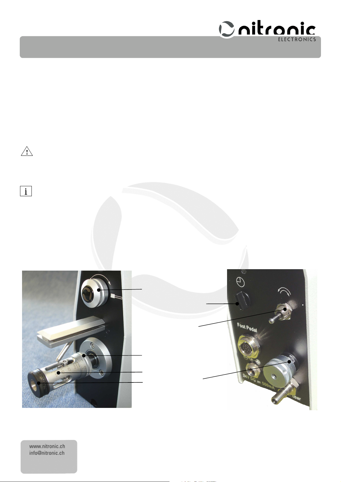
4. Diameter 31.Rotation time / diameter feed rate
5. Stripping head with length scale 30. Counterclockwise / no rotation / clockwise
2. Length 32. Wayback (ST215 only)
17. Centering
2
4
17
Fig. 1 Fig. 2
32
Page 5
5
Nitronic
NitronicNitronic
Nitronic
AG
AGAG
AG
Mattenstrasse 11
Switzerland
Fax +41 32 373 70 75
Sdasdasdsdfdsdcdscsdcdcd
CH – 2555 Brügg Tel. +41 32 373 70 70
cdcsc
Placing
Placing in
Placing Placing
in operation
operation
in in
operationoperation
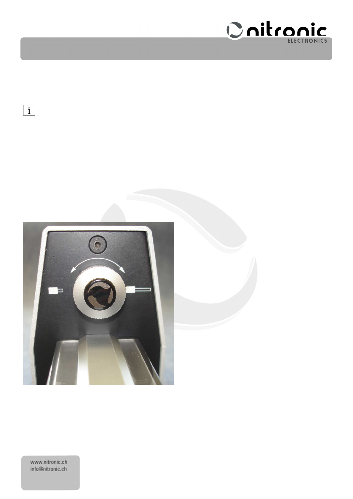
The order of the settings must be observed because due to the construction, any changes to the stripping
diameter will render it necessary to make adjustments to the stripping length!
The protective cover must be removed for settings to the stripping head, i.e. the centering device or the stripping
diameter. This can be removed or refitted by simply pulling out or pushing in. The protective cover must be pushed right
up to the front panel; remove any scraps of cable between the cover and the front panel.
For safety reasons the machine cannot be started without the protective cover in place!
The blue LED will blink 3 times if the cover is not mounted and you try to start the stripping cycle.
Setting the
Setting the centering
Setting the Setting the
• Measure the external diameter, e.g. with the slide gauge or centering device open; introduce the cable and
• The cable must in no event be clamped but should be movable in the centering device without play.
Setting the
Setting the DDDDiameter
Setting the Setting the
• Evaluate the cable conductor diameter, e.g. with the sliding gauge.
• Check that the Wayback is set to 0 (ST215W only).
• Then set a somewhat large value at the diameter scale (ca.
• If required, the diameter adjustment can be blocked with the supplied grub screw. Remove the existing grub
centering device
centering centering
device
devicedevice
close the centering device.
Special regulations, (e.g. military) stipulate blocking of the centering device. This can be carried out with the light
Allen screw, using the Allen key supplied.
No not confuse the light Allen screw with the black one. If you should slacken the black Allen screw, the
centering device will be displaced and will have to be recalibrated.
iameter
iameteriameter
(ca. + 0.1mm
graduated in 0.01mm
0.01mm (0.001 Inch)
0.01mm0.01mm
(0.001 Inch).
(0.001 Inch)(0.001 Inch)
+ 0.1mm or 0.01 Inch
(ca. (ca.
+ 0.1mm+ 0.1mm
or 0.01 Inch)))). The diameter scale is
or 0.01 Inchor 0.01 Inch
When setting the diameter, always turn from a larger diameter to the desired value. For example; if the existing
setting is 0.95mm and you wish to set 1.00mm, first open to ca. 1.50mm and then turn to 1.00mm.
If the stripping diameter is set too small, the blades will cut into the conductor and a high pulling force will be
required to pull off the insulation. This can damage the blades.
screw at the side of the diameter adjustment using the Allen key supplied, and carefully screw in the longer
grub screw as far as the stop.
Page 6
6
Nitronic
NitronicNitronic
Nitronic
AG
AGAG
AG
Mattenstrasse 11
Switzerland
Fax +41 32 373 70 75
Sdasdasdsdfdsdcdscsdcdcd
CH – 2555 Brügg Tel. +41 32 373 70 70
cdcsc
Setting the Wayback (ST215W only)
Setting the Wayback (ST215W only)
Setting the Wayback (ST215W only)Setting the Wayback (ST215W only)
The Wayback is an opening of the blades before pulling off the jacket.
The Wayback is only active when pulling off without rotation. The Switch 30 must be in the middle position.
• Set the Wayback to 0.00mm firstly
• Raise the Wayback until the desired stripping results are reached.
• The Wayback scale is graduated in 0.01mm
0.01mm (0.0005 Inch)
0.01mm0.01mm
(0.0005 Inch). That means that with a full turn the Wayback will be
(0.0005 Inch)(0.0005 Inch)
0.2mm (0.008 Inch) in diameter.
Setting
Setting the
SettingSetting
the LLLLength
ength
thethe
engthength
• Set the desired stripping length with the length setting knob and read off the length at the length scale.
Fig. 3
Page 7

7
Nitronic
NitronicNitronic
Nitronic
AG
AGAG
AG
Mattenstrasse 11
Switzerland
Fax +41 32 373 70 75
Sdasdasdsdfdsdcdscsdcdcd
CH – 2555 Brügg Tel. +41 32 373 70 70
cdcsc
Setting the rotation duration / incision rat
Setting the rotation duration / incision rateeee
Setting the rotation duration / incision ratSetting the rotation duration / incision rat
The rotation duration and the incision rate are selected with the same switch. The longer the setting of the rotation
duration, the shorter the incision rate. At step 0, i.e. the shortest rotation duration, the blades close very quickly. At step
9, the longest rotation duration, the blades close very slowly.
The stripping head may not be externally braked whilst running. Otherwise there is no guarantee that the blades
will close to the set diameter, particularly with step 9.
Counterclockwise
Counterclockwise or cl
Counterclockwise Counterclockwise
or clockw
ockwise rotation
or clor cl
ise rotation / no rotation
ockwockw
ise rotationise rotation
/ no rotation
/ no rotation/ no rotation
The desired rotation direction can be set with the changeover switch. This is especially important for the twisting of
stranded wires. The correct choice of rotation direction can also positively influence stripping quality when stripping
micro-coaxial cables.
ST215W only:
In the middle position, the stripping head will stop. Then you can pull off the cable while the blue LED is on. After that
the machine starts the cleaning cycle.
Page 8
8
Nitronic
NitronicNitronic
Nitronic
AG
AGAG
AG
Mattenstrasse 11
Switzerland
Fax +41 32 373 70 75
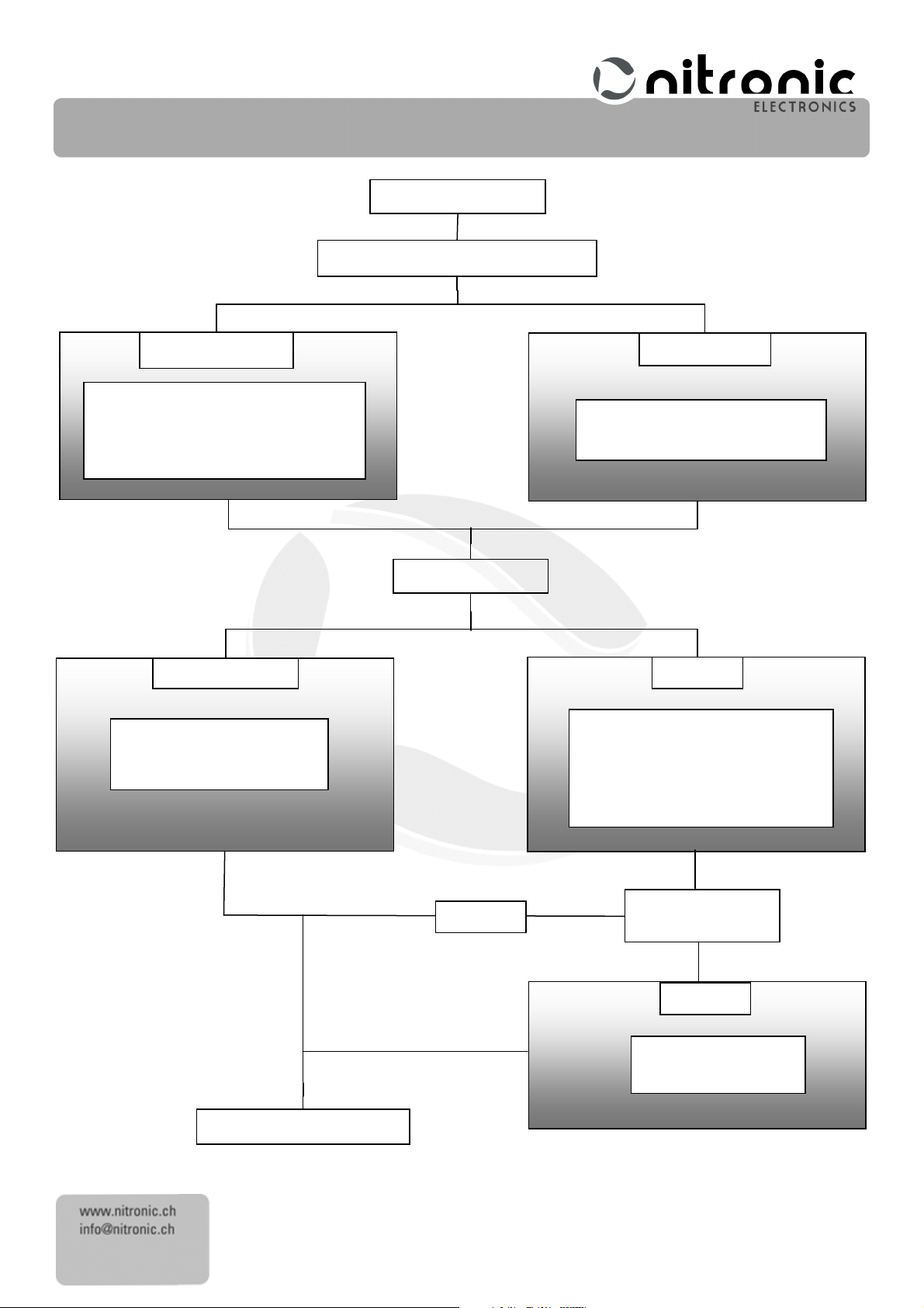
Adjust
machine
Insert the cable end to the sensor
With
foot pedal
When the cable touches the
cycle.
Start the stripping cycle with the
Full strip?
No
Yes
Wait until the stripping head
Wait until the
LED is on or the
while the LED is on
!
End of
st
ripping
cycle
Twisting
?
(ST215W
only)
No
Cleaning
cycle
Yes
Sdasdasdsdfdsdcdscsdcdcd
CH – 2555 Brügg Tel. +41 32 373 70 70
cdcsc
Without foot pedal
activation sensor, the machine will
automatically start the stripping
stops before pulling out the
foot pedal
solenoid air valve is activated (you
hear the air blowing out the air
nozzle). Now pull out the cable
Fig. 4
(starts automatically)
Page 9
9
Nitronic
NitronicNitronic
Nitronic
AG
AGAG
AG
Mattenstrasse 11
Switzerland
Fax +41 32 373 70 75
Sdasdasdsdfdsdcdscsdcdcd
CH – 2555 Brügg Tel. +41 32 373 70 70
cdcsc
Maintenance
Maintenance
MaintenanceMaintenance
The only maintenance required is cleaning of the stripping head.
Lubrication
Lubrication
LubricationLubrication
The ST215 is designed in such a way that it does not require the application of grease or oil. In order to ensure
correct function and long service life avoid contaminating the tool with greasy or oily substances.
Cleaning
Cleaning
CleaningCleaning
The waste created by the stripping should be automatically removed by the air blast.
• Clean the surface of the stripping head using a dry, clean brush only.
• Dirt on the housing or the stripping head can be removed using a cloth dampened with kerosene.
Do never use solvent like thinner to clean the machine!
Changing the stripping blades
Changing the stripping blades
Changing the stripping bladesChanging the stripping blades
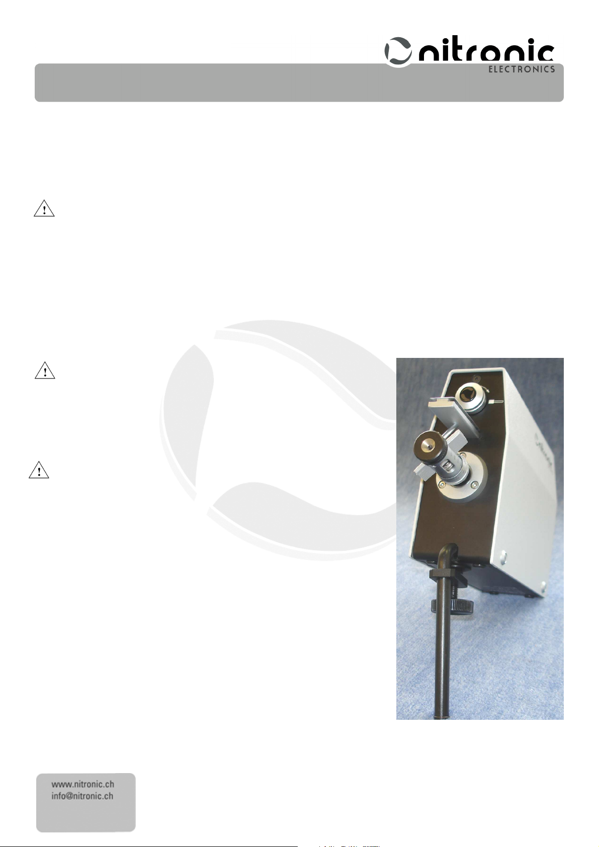
The stripping blades may only be inspected and replaced by a suitably
trained person.
• Remove the power cord, foot pedal and compressed air.
• To facilitate the handling with the machine, arrange the machine with aid
of the bench clamp. See Fig. 5.
• Set the diameter setting to 0.2mm (0.008 Inch).
• Set the length setting to the hindmost position.
Fig. 5
Page 10
10
Nitronic
NitronicNitronic
Nitronic
AG
AGAG
AG
Mattenstrasse 11
Switzerland
Fax +41 32 373 70 75
Sdasdasdsdfdsdcdscsdcdcd
CH – 2555 Brügg Tel. +41 32 373 70 70
cdcsc
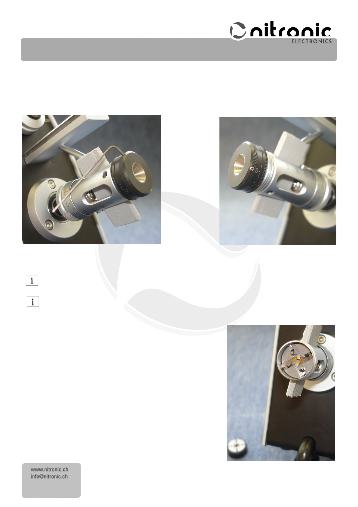
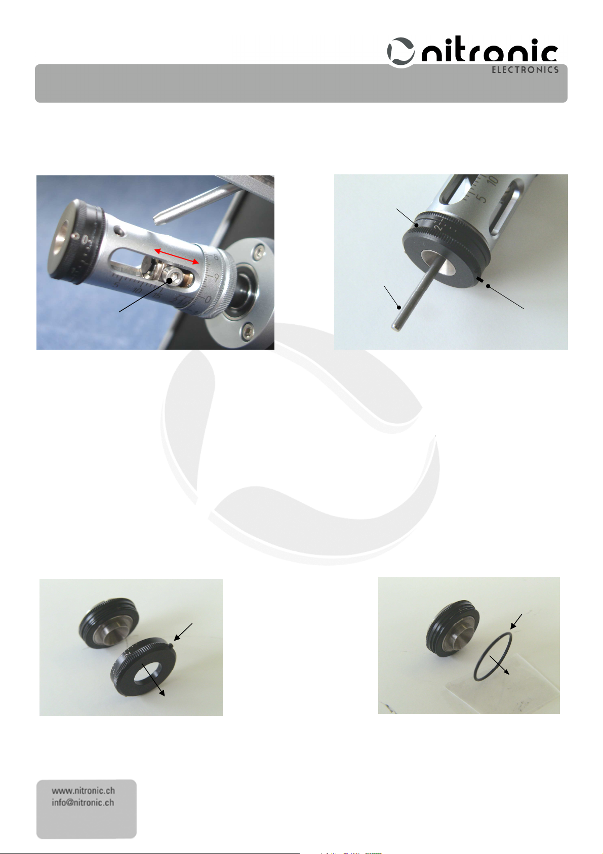
• Insert the position retainer corresponding to Fig. 6 in hat stripping head. For this, slide the big Allen screw near the
length scale, to the back. This procedure allows to easily insert the new blades.
• If the centering unit is blocked, loose the bright and small Allen screw.
• Loose the black and small Allen screw of the centering unit.
• Loose the entire centering unit and pull it out Fig.
7
.
Fig. 6 Fig. 7
Now you can see the four stripping blades Fig.
8
In order to avoid losing the very small stripping blades, we recommend that you put down a dark-colored,
smooth mat and use a pair of tweezers.
All four stripping blades must be changed at the same time in order to maintain a consistent stripping quality.
• Remove each stripping blade (8)
• If necessary, carefully clean the guide plate (9)
• Insert new stripping blades (8)
(8) individually from the guide plate (9)
(8)(8)
(9) with a dry brush
(9)(9)
(8) individually. As far as possible, align the
(8)(8)
(9)....
(9)(9)
stripping blades accurately with the track so that the blades do not
subsequently jam.
• Insert the centering unit carefully, but do not yet tighten
do not yet tighten it
do not yet tightendo not yet tighten
it.
itit
• Remove the position retainer.
• Set the diameter scale to 0.0mm (0.0 Inch).
Fig. 8
Page 11
11
Nitronic
NitronicNitronic
Nitronic
AG
AGAG
AG
Mattenstrasse 11
Switzerland
Fax +41 32 373 70 75
17
30
19
6
19
20
17
Sdasdasdsdfdsdcdscsdcdcd
CH – 2555 Brügg Tel. +41 32 373 70 70
cdcsc
• Slowly push the big Allen screw (6)
(6) back and forth. This will cause the four stripping blades to automatically fit into
(6)(6)
the tracks on the guide plate Fig. 9.
• Only now tighten the centering unit.
Fig. 9 Fig. 10
• By rotating the centering scale (17),
rotating the centering scale (17)
• Loosen screw (19)
((((black
black)))) and remove calibrating pin (30)
blackblack
(19) (black)
(black) and turn the centering scale (17)
(19)(19)
(black)(black)
(17), fully open the centering jaws (25)
(17),(17),
(17) close the centering jaws as far as the calibrating pin (30)
(17)(17)
(17) clockwise to diameter 2.0
(17)(17)
(30).
(30)(30)
The ST215 is now ready for use.
Dismantling
Dismantling the
DismantlingDismantling
the centering
centering unit
thethe
centering centering
unit
unitunit
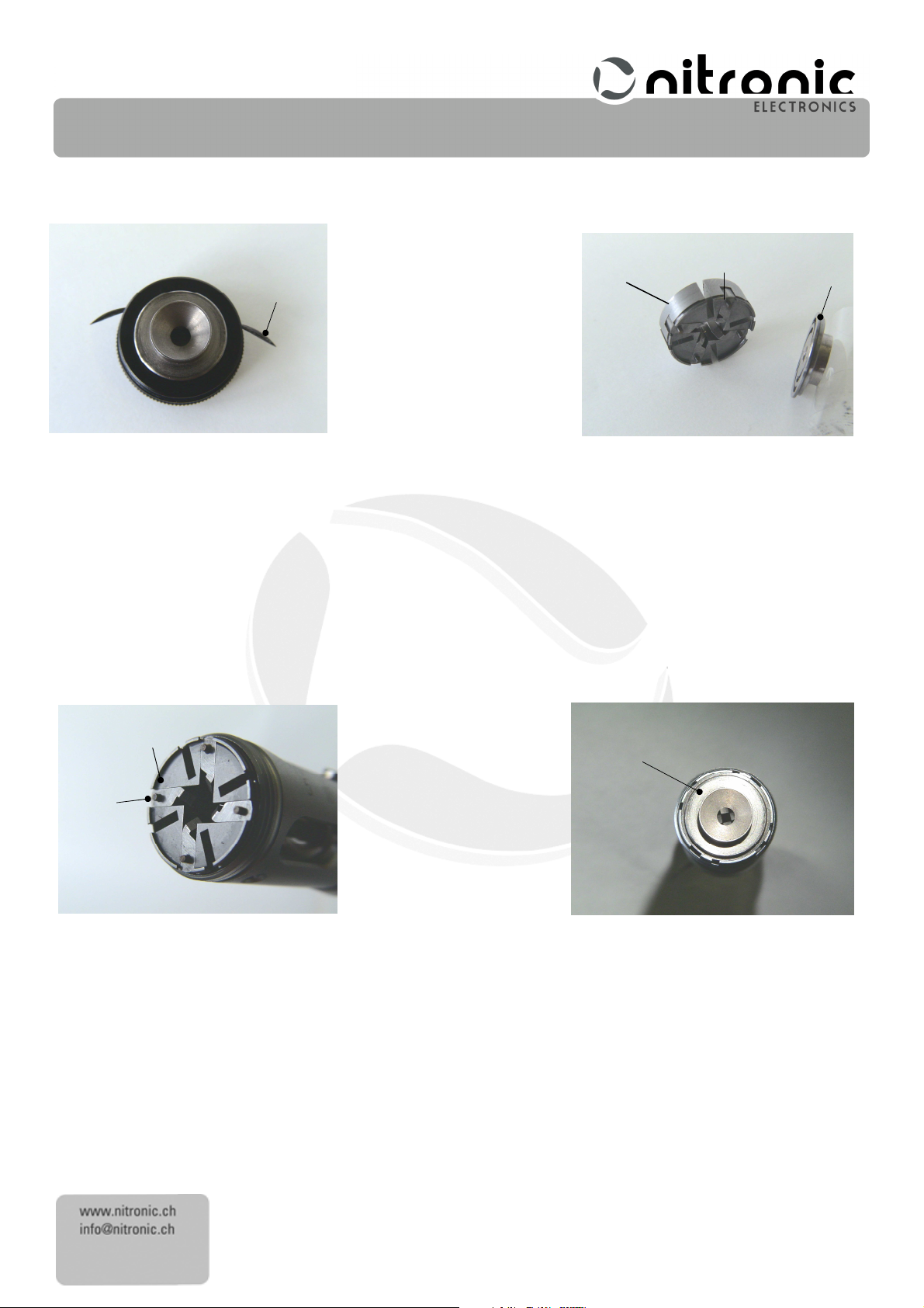
• Loosen screw (19)
• Lift off the O-ring (20)
(19) (black) and remove centering scale (17)
(19)(19)
(20) and take it out Fig.
(20)(20)
(17) with a slight turning movement Fig. 11.
(17) (17)
12
.
(25) and insert the calibrating pin (30)
(25)(25)
(30)
Fig.
(30)(30)
2.0 mm
mm. Retighten screw (19)
2.0 2.0
mmmm
(30). Then by
(30)(30)
10
.
(19)
(19) (19)
Fig. 11
Fig. 12
Page 12
12
Nitronic
NitronicNitronic
Nitronic
AG
AGAG
AG
Mattenstrasse 11
Switzerland
Fax +41 32 373 70 75
23
25
26
22
23
26
Sdasdasdsdfdsdcdscsdcdcd
CH – 2555 Brügg Tel. +41 32 373 70 70
cdcsc
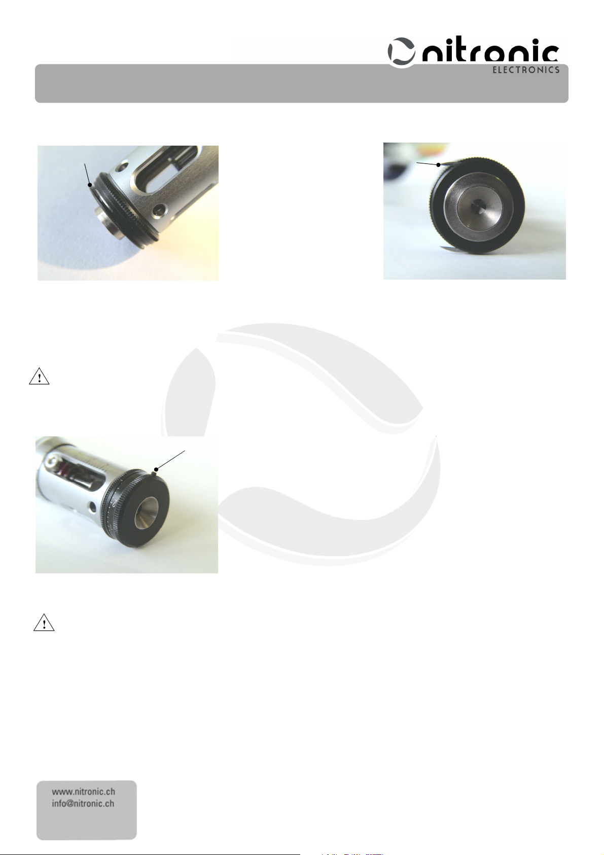
Push the two keys (22)
• The guide plate (23)
(22) out of the guides with a pair of tweezers and remove them Fig. 13.
(22)(22)
(23), the centering jaws (25)
(23)(23)
(25) and the helixes (26)
(25)(25)
Fig. 13
Assembling
Assembling the
Assembling Assembling
the centering
centering device
thethe
centering centering
device
devicedevice
• Reinstall guide plate (23)
• Push all four centering jaws (25)
(23) and insert the centering jaws (25)
(23)(23)
(25) outwards to the stop on the stripping head and carefully put the helixes (26)
(25)(25)
place Fig. 16.
(26) can now be removed together Fig. 14.
(26)(26)
Fig. 14
(25) individually Fig. 15.
(25)(25)
(26) in
(26)(26)
25
Fig. 15 Fig. 16
• By rotating the helixes (26)
(26) check that the centering jaws can close smoothly and simultaneously. If necessary
(26)(26)
repeat the procedure.
Page 13
13
Nitronic
NitronicNitronic
Nitronic
AG
AGAG
AG
Mattenstrasse 11
Switzerland
Fax +41 32 373 70 75
18
19
Sdasdasdsdfdsdcdscsdcdcd
CH – 2555 Brügg Tel. +41 32 373 70 70
cdcsc
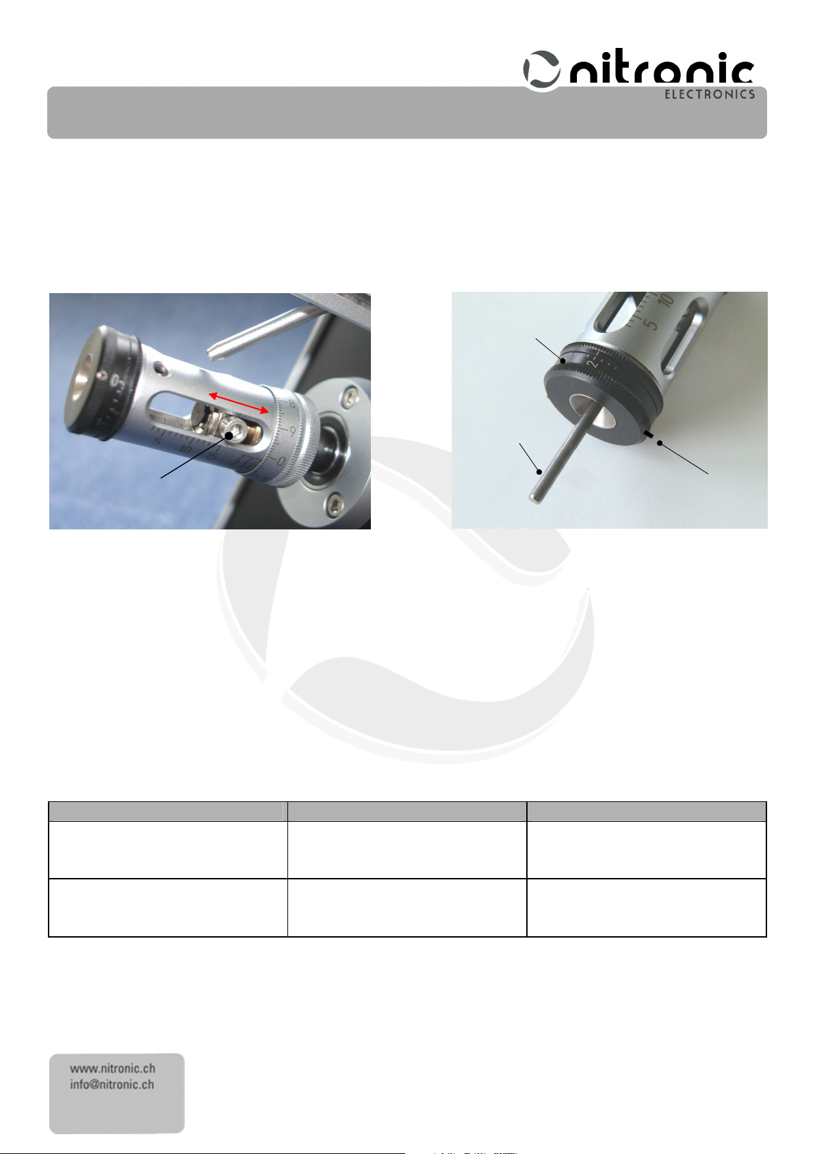
• Screw on nut (18)
(18) and tighten up Fig. 17.
(18)(18)
Fig. 17
• Insert the two keys (22)
(22) and install the previously-greased O-ring (20
(22)(22)
The two keys (22)
(22) must be inserted flush with the inside diameter of the slot.
(22)(22)
• Push centering scale (17)
(17) with a slight turning movement to the stop but do not yet tighten screw (19)
(17)(17)
19.
(20)
) Fig.
(20(20
) )
22
Fig. 18
18
.
(19) (black) Fig.
(19) (19)
Fig. 19
The centering device must now be calibrated in the next operating step.
Fit the stripping blades and c
Fit the stripping blades and calibrating the cen
Fit the stripping blades and cFit the stripping blades and c
If the centering scale (17)
(17) cannot be pushed over the O-ring the two keys (22)
(17)(17)
alibrating the centering
alibrating the cenalibrating the cen
tering unit
tering tering
unit
unitunit
(22) are not properly.
(22)(22)
Page 14
14
Nitronic
NitronicNitronic
Nitronic
AG
AGAG
AG
Mattenstrasse 11
Switzerland
Fax +41 32 373 70 75
17
30
19
6
Fault
FaultFault
Fault
Diagnos
DiagnosDiagnos
Diagnos
is
isis
is
Fault
Fault Fault
Fault
rectification
rectificationrectification
rectification
Inside con
ductor, screen or dielectric
Cable
is
very eccentric
Reduce centering diameter in steps
Jacket
cannot be stripped off
Very small difference in diameter
Reduce centering diameter in small
Sdasdasdsdfdsdcdscsdcdcd
CH – 2555 Brügg Tel. +41 32 373 70 70
cdcsc
• Loosen the centering unit so that it is not tightened.
• Set the diameter scale to 0.0mm (0.0 Inch).
• Slowly push the big Allen screw (6)
(6) back and forth. This will cause the four stripping blades to automatically fit into
(6)(6)
the tracks on the guide plate Fig. 20.
• Now tighten the centering unit.
Fig. 20 Fig. 21
• Tighten a bit the screw (19)
• By rotating the centering scale (17),
rotating the centering scale (17)
• Loosen screw (19)
screw (19) (
(19) (black
(19) ((19) (
(19) ((((black)
(19)(19)
black)))) and remove calibrating pin (30)
blackblack
(19) (black)
(black)
(19)(19)
(black)(black)
(17), fully open the centering jaws (25)
(17),(17),
(17) close the centering jaws as far as the calibrating pin (30)
(17)(17)
black) and turn the centering scale (17)
black)black)
(30).
(30)(30)
(17) clockwise to diameter 2.0
(17)(17)
(25) and insert the calibrating pin (30)
(25)(25)
The ST215 is now ready for use.
Error
Error sources
sources
Error Error
sourcessources
Faults
Faults on
FaultsFaults
on cable
on on
cut into
cable
cablecable
between Jacket and conductor.
(30). Then by
(30)(30)
(30)
Fig. 21.
(30)(30)
2.0 mm
mm. Retighten carefully
2.0 2.0
mmmm
steps
Page 15
15
Nitronic
NitronicNitronic
Nitronic
AG
AGAG
AG
Mattenstrasse 11
Switzerland
Fax +41 32 373 70 75
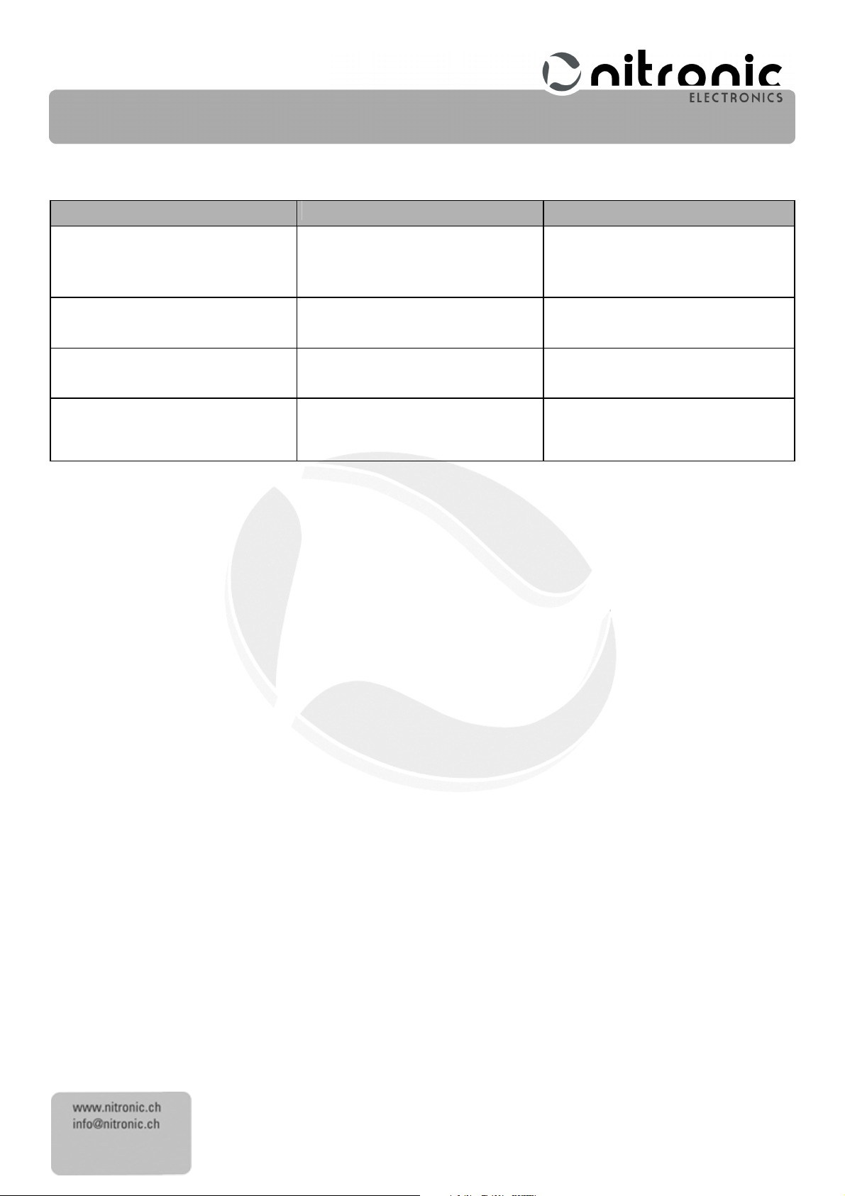
Fault
FaultFault
Fault
Diagnos
DiagnosDiagnos
Diagnos
is
isis
is
Fault
Fault Fault
Fault
rectification
rectificationrectification
rectification
Can not insert the cable
Cable rests in the stripping head
Clean, with startin
g the stripping cycle
Bad stripping quality
Strippi ng blades are
broken
or used
Change the stripping blades
The
blue LED is blinking 3 times
The safety shield is no
t mounted
Insert the safety shield
Sdasdasdsdfdsdcdscsdcdcd
CH – 2555 Brügg Tel. +41 32 373 70 70
cdcsc
Faults on mach
Faults on machine
Faults on machFaults on mach
ine
ineine
several times.
Page 16
16
Nitronic
NitronicNitronic
Nitronic
AG
AGAG
AG
Mattenstrasse 11
Switzerland
Fax +41 32 373 70 75
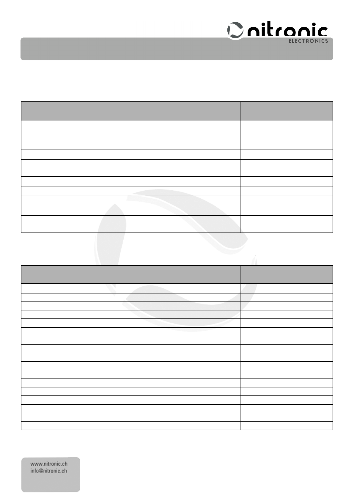
Qty
QtyQty
Qty
....
Description
DescriptionDescription
Description
Article
ArticleArticle
Article
NNNN
umber
umberumber
umber
1 Stripping machine
ST215
/ ST215 Inch
010083
/ 010307
1 Stripping machine ST215
W / ST215
W Inch 010305 / 010314
1 Bench
clamp
010177
1 Power
supply
with
Adapter Set
010113
1 C
oupler
for air hose
010151
1 Allen key
for diameter blocking
EN-
7411
1 Stud screw for diameter blocking
BN-
617 M2x8
1 Position retainer
ST-
0900
1 Operating
Instructions
English
EnglishEnglish
English
or
EN-7120
EEEE
1 Allen key for centering unit
EN-
7412
1 Calibrating
mandrel
BN-
1208
Qty
QtyQty
Qty
....
Description
DescriptionDescription
Description
Article
ArticleArticle
Article
NNNN
umber
umberumber
umber
1 Set
Stripping
blades
HSS (4
pcs.)
010075
1 Set
Stripping blades Titanium coated carbide (4 pcs.)
01007
9
1 Set
Input c
onnectors for power supply ( EU,
USA
, UK,
SAA ) 010115
1 Cover
010322
1 Length
button
010404
1 Guide
plate
010225
1 Solenoid
air valve
010149
1 Blocking
screw
M1.4 x
2.5 BN-24 M1.4x2.5
1 Stud screw for diameter blocking
BN-
617 M2x8
Sealing Cap wit
h Nitronic Logo
010216
Sdasdasdsdfdsdcdscsdcdcd
CH – 2555 Brügg Tel. +41 32 373 70 70
cdcsc
Basic
Basic EEEEquipment
Basic Basic
quipment,
quipmentquipment
, SSSSpare
pare Parts
, ,
pare pare
Parts,
PartsParts
, Options
Options
, ,
OptionsOptions
Basic
Basic Equipment
Equipment ST215
Basic Basic
EquipmentEquipment
ST215
ST215ST215
Spare
Spare Parts
Spare Spare
Parts
PartsParts
Operating Instructions German
German
GermanGerman
EN-7120DDDD
Page 17
17
Nitronic
NitronicNitronic
Nitronic
AG
AGAG
AG
Mattenstrasse 11
Switzerland
Fax +41 32 373 70 75
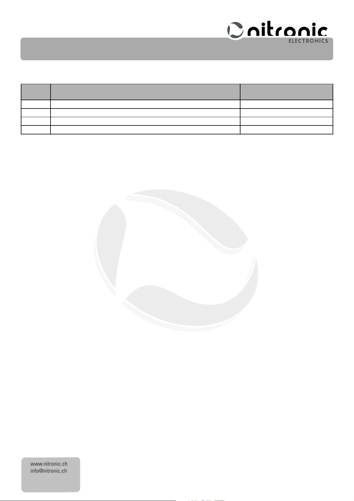
Qty
QtyQty
Qty
....
Description
DescriptionDescription
Description
Article
ArticleArticle
Article
NNNN
umber
umberumber
umber
1 Foot pedal
010084
1 Micro Filter
010346
2 Port for Micro Filter straight
010347
Sdasdasdsdfdsdcdscsdcdcd
CH – 2555 Brügg Tel. +41 32 373 70 70
cdcsc
Option
Optionssss
OptionOption
Technical
Technical Data
TechnicalTechnical
Wire size range 0.08 mm (0.003”) to 2.00 mm (0.08“) (12 – 40 AWG)
Outer cable diameter max. 2.5 mm (0.1“)
Stripping length up to 13mm
Cycle time 0.3 sec. up to 6.2 sec. (stripping cycle), 10 different steps
Rotation / Twisting Clockwise / Counter clockwise
Diameter Scale 0.01 mm (0.001 Inch)
Wayback Scale (ST215W only) 0.01 mm (0.0005 Inch)
Length scale 1.0 mm (.06 Inch)
Dimensions LxWxH 210 x 54 x 126 mm (10 x 2.2 x 5 Inches)
Weight 850g
Stripping blades 4 pcs. Carbide, Titanium coated
Power supply (Primary) 100-230 VAC, < 0.6A RMS, 47-63 Hz
Power supply ST215 (Secondary) 24 VDC
Compressed air 5 to max.8 Bar
Outer hose diameter 6mm (0.24“)
We reserve the right to make technical changes at any time
We reserve the right to make technical changes at any time!!!!
We reserve the right to make technical changes at any timeWe reserve the right to make technical changes at any time
Data
DataData
 Loading...