

Page 1

XHDART
User manual
Page 2

User’s Manual | 2
Safety Information
Before You Begin
Read these instructions before installing or operating this product.
Note: This installation should be made by a qualified service person and should conform to local
codes.
This manual provides installation and operation information. To use this document, you must
have the following minimum qualifications:
A basic knowledge of CCTV systems and components
A basic knowledge of electrical wiring and low-voltage electrical connections
Intended use
Only use this product for its designated purpose; refer to the product specification and you
documentation.
Customer Support
For assistance in installing, operating, maintaining and troubleshooting this product refer to this
document and any other documentation provided. If you still have questions, please contact
Norbain Technical Support and Sales:
Norbain SD, 210 Wharfedale Road, IQ Winnersh, Wokingham, Berkshire RG41 5TP, England.
UK +44 (0) 118 912 5000
Note: You should be at the equipment and ready with details before calling Technical Support.
Conventions Used in this Manual
Boldface or button icons highlight command entries. The following warning, CAUTION and Note
statements identify potential hazards that can occur if the equipment is not handled properly:
* Warning:
Improper use of this equipment can cause severe bodily injury or equipment
damage.
** Caution:
Improper use of this equipment can cause equipment damage.
Note: Notes contain important information about a product or procedure.
This apparatus is manufactured to comply with the radio interference.
A Declaration of Conformity in accordance with the following EU standards has
been made. The manufacturer declares that the product supplied with this
document is compliant the provisions of the EMC Directive 2004/108/EC, the CE
Marking Directive 93/68 EEC and all associated amendments.
All lead-free products offered by the company comply with the requirements of
the European law on the Restriction of Hazardous Substances (RoHS) directive:
2011/65/EU, which means our manufacture processes and products are strictly
“lead-free” and without the hazardous substances cited in the directive.
Page 3
3 | Full HD Digital Video Recorder
The crossed-out wheeled bin mark symbolizes that within the European Union the
product must be collected separately at the product end-of-life. This applies to your
product and any peripherals marked with this symbol. Do not dispose of these
products as unsorted municipal waste.
* This symbol indicates electrical warnings and cautions.
** This symbol indicates general warnings and cautions.
NORBAIN SD reserves the right to make changes to the product and specification of the product
from time to time without prior notice.
WARNINGS AND CAUTIONS:
To reduce the risk of fire or electric shock, do not insert any metallic objects through the
ventilation grills or other openings on the equipment.
CE COMPLIANCE STATEMENT
WARNING
This is a Class A product. In a domestic environment this product may cause radio interference in
which case the user may be required to take adequate measures.
Page 4
User’s Manual | 4
Contents
CHAPTER 1 : DVR USER MANUAL
1 GETTING STARTED 7
1.1 Checking Supplied Items 7
1.2 Connecting Peripheral Device 8
1.3 System Startup and Shutdown 10
2 EXPLANATION FOR EACH FUNCTION 12
2.1 Front Panel 12
2.2 Rear Panel 14
3 OPERATION 16
3.1 User Log-in 16
3.2 Live Display Mode 17
3.3 PTZ Operation 22
3.4 Spot out Monitor 23
3.5 Playback of Recorded Video 24
3.6 Search Recording Image 26
3.7 DST Setting 30
3.8 Screen Saver 31
4 SETTING 32
4.1 System 33
4.2 Device 39
4.3 Record 45
4.4 Network 48
4.5 Backup 54
4.6 Quick Setup 56
5 WEB SURVEILLANCE 57
5.1 Web Login 57
5.2 Web Configuration 58
5.3 Web monitoring 60
5.4 Web Playback 63
Page 5
5 | Full HD Digital Video Recorder
CHAPTER 2 : CMS CLIENT SOFTWARE USER MANUAL
6 CMS USER GUIDE 65
6.1 PC REQUIREMENT 65
6.2 INSTALL 65
6.3 UNINSTALL 67
6.4 BASIC OPERATION 69
CHAPTER 3 : MAC ACS CLIENT SOFTWARE USER MANUAL
7 MAC ACS USER GUIDE 106
7.1 System Requirement 106
7.2 Install 106
7.3 Basic Operation 108
CHAPTER 4 : MOBILE PHONE SOFTWARE USER MANUAL
8 MOBILE PHONE SOFTWARE USER GUIDE 116
8.1 iPhone application software 116
8.2 Basic Operation 117
8.3 iPhone application software 125
APPENDIX : DYNDNS SITE REGISTRATION 127
APPENDIX : NETWORK SETUP FOR EXTERNAL USAGE 130
APPENDIX : SPECIFICATION 131
Page 6

User’s Manual | 6
Chapter 1
DVR USER MANUAL
Page 7
7 | Full HD Digital Video Recorder
1 GETTING STARTED
1.1 Checking Supplied Items
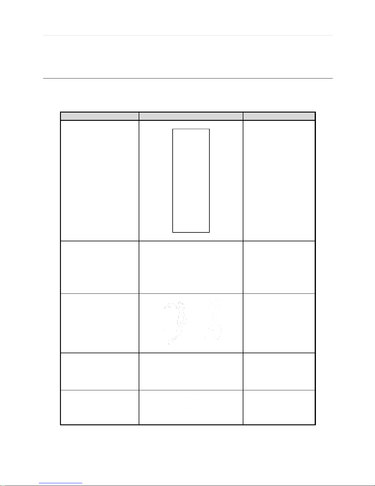
Make sure that you have the following items supplied with your DVR. If any of these items are missing or damaged, notify
your vendor immediately. Keep the packing utilities for moving or storage purposes afterwards.
Items
Photo
Quantity
Quick Start Guide
1 Set
CD (Manual & Software)
1 Set
12V DC Adaptor
Power Cable
1 Set
USB Mouse
1 Set
Screws
1 Set
Page 8

User’s Manual | 8
1.2 Connecting Peripheral Device
This section describes how to connect peripheral devices efficiently to the DVR.
Install the DVR on flat surface. If required, attach a rubber mount for installation. If a 19-inch rack is used with 1.5U Height
case, it is recommend to install the system on a shelf and use 2.5~3U (1U=1.75 inch or 4.45 cm) space for proper ventilation.
4ch 1HDD type
8ch 1HDD type
NOTE
Install the system in a location with good ventilation to prevent overheating.
Page 9

9 | Full HD Digital Video Recorder
16ch 1HDD type
16ch 2HDD / Front Key type
WARNING !
※When connecting power cord to the system, it is strongly recommended first to plug the power cord
to the system and then plug the other side of power cord into the wall socket.
Page 10

User’s Manual | 10
1.3 System Startup and Shutdown
1.3.1 System Startup
After connecting peripheral devices such as cameras, monitors and a mouse to the DVR, power up the DVR by connecting
DC12V adaptor to the power jack on the rear panel. The boot log will display as shown below. Please wait until the boot
process completes.
Login with ‘User Name’ at the login window which will appear as shown below.
There is only one Administrator Account configurable in the DVR system. It is assigned with an unchangeable User ID
marked as ‘admin’. The default password is empty (No Password). Administrator account has full access to the DVR and its
configurable parameters. The Administrator Account also has the ability to create new users and to assign rights to the new
user accounts. Those new users created by ‘admin’ account can also login with a specific password set by ‘admin’ account.
NOTE
Do not forget the administrator’s password that was set for the first time. In case the password is lost,
contact your vendor.
NOTE
The mouse is included. In case you need to replace it, it is highly recommended to choose well-known
major brands such as DELL, MICROSOFT, LOGITECH, or SAMSUNG.
Page 11
11 | Full HD Digital Video Recorder
1.3.2 System shutdown and change password
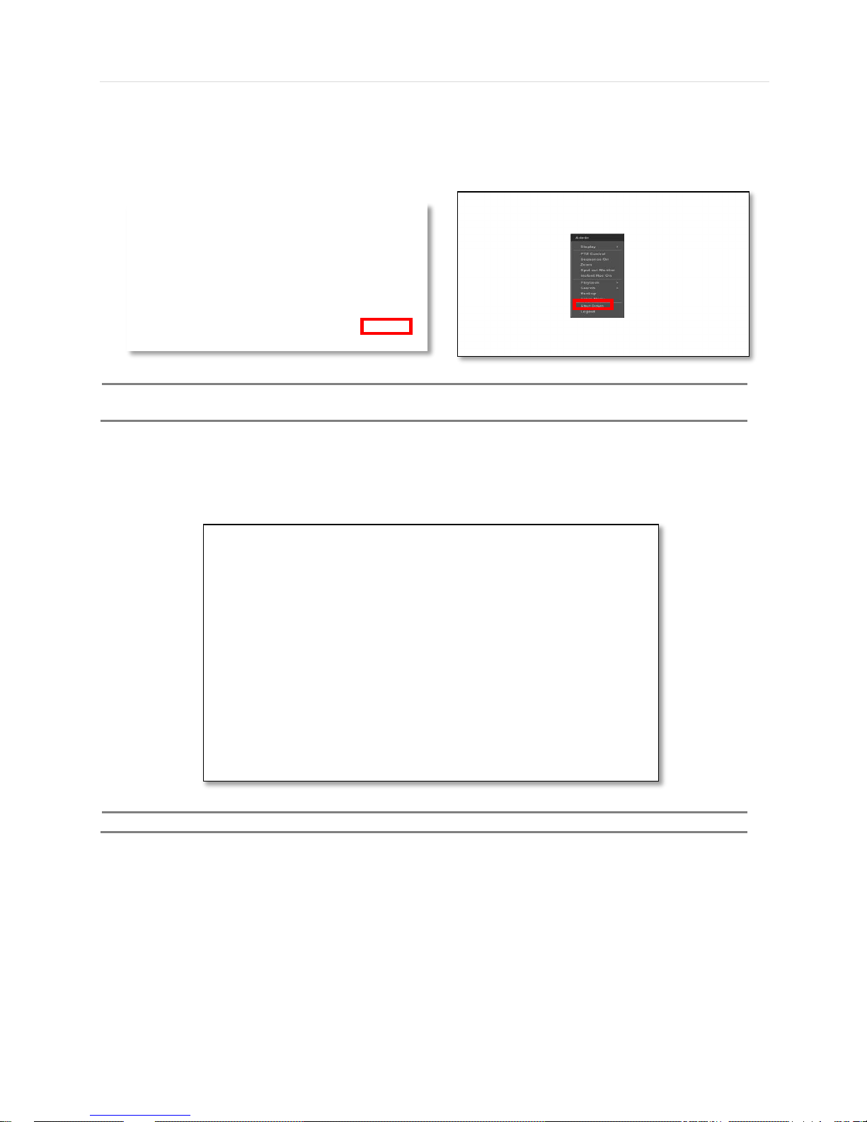
Option 1. Click the Shutdown button and input password on pop-up to power off the DVR
Option 2. Click the right button on the mouse and select the Shut Down to power off the DVR.
NOTE
It is not recommended to disconnect the power cable abruptly from the back of the DVR because it may
affect the DVR and Hard Drive.
The default password for ‘admin’ account is none. Therefore, just click ‘Enter’ button on the dial pad. If you changed the
password for ‘admin’ account, please type in the changed password to login.
NOTE
User can type in the password using the virtual keyboard.
Page 12

User’s Manual | 12
2 EXPLANATION FOR EACH FUNCTION
2.1 Front Panel
4/8/16ch 1HDD type
16ch Front Key type
1
Playback Speed Control
Playback Speed Control(Short Press) when Playback
Reverse Step Playback(Short Press) when Pause
First Data Playback(Long Press)
2
Forword & Backward Play
Pause
Forward play & Backward Play(Long Press)
Pause(Short Press)
3
Playback Speed Control
Playback Speed Control(Short Press) when Playback
Forward Step Playback(Short Press) when Pause
Last Data Reverse Playback(Long Press)
4
Search
goto Search menu(Short Press)
5
Book-mark / Instant play
Book-Mark(Short Press) / Last Data Reverse Playback(Long Press)
6
Instant Record / Spot out
Emergency Recording(Short Press)
Spot out monitor(Long Press)
7
PTZ / I-backup
Bring Up PTZ Camera Control(Short Press)
Used to initiate instant back up(Long Press)
8
Mode
Change screen mode(Short Press)
9
USB Port
USB port(Ver.2.0)for mouse operation or backup or F/W update
10
LED Indicator
Indicates system status Power, Record, Network
11
Menu / Exit
Toggles On or Off Menu Setup Display
12
Enter
Select value or setting
13
Direction
Move to the direction that user wants to select
14
DVD±RW
DVD±RW door
Page 13

13 | Full HD Digital Video Recorder
NOTE
I- Backup (Instant Backup)
In playback mode, the user can press the “I-backup” button on the frontal keypad to configure both “start” and
“End” time. Once the “Start” and “End” time is set, click the “Start” button to start the backup process.(Front
Key type)
Page 14

User’s Manual | 14
2.2 Rear Panel
4ch 1HDD type
8ch 1HDD type
16ch 1HDD type
Page 15

15 | Full HD Digital Video Recorder
16ch / Front Key type
No.
Name
Description
1
Video-In
Camera inputs (Supports NTSC/PAL)
2
Audio-In
Audio Input Device (with Amplifier)
3
Audio-Out
Audio Output Device (with Amplifier)
4
USB Port
USB 2.0 Port for Mouse Operation, Backup Device, or Firmware Update
5
HD OUTPUT
HD OUTPUT
6
LAN Port
1 x 10/100/1000M
7
Power Input
4ch : 12V/2A 8ch : 12V/3A 16ch : 12V/5A
8
Alarm Output
Alarm Output
9
Sensor Input
Sensor Input
10
RS-485 Port
PTZ Dome Camera or External Keyboard Controller connection
11
VGA
D-sub VGA Output
12
SPOT
SPOT Output
Note
Carefully check whether the specifications of the peripheral devices match the DVR’s specifications.
Page 16

User’s Manual | 16
3 OPERATION
3.1 User Log-in
The DVR has various setting categories. The administrator can set the system password and <User> to prevent
unauthorized changes to setting values and alteration of recorded file.
Enter the <Admin> or <User> password which had been set by using the virtual keyboard.
NOTE
1) <LOGIN> window will be permanently displayed in monitor as above picture until user logs in with the
right ID and password.
2) If it is set as Auto Log-In, DVR does not require LOG-IN. (Please refer to 4.1.2 User.)
Page 17

17 | Full HD Digital Video Recorder
3.2 Live Display Mode
3.2.1 Full HD(1080p) Live Display
Full HD Live Display can be supported in live mode by using its HD output.
Able to set max 4k(3840x2160) : HD output and supplied 4K monitor
NOTE
HD Resolution 4K(3840x2160) support only 8ch and 16ch. 4ch is not support 4K resolution
<Full HD Live Display>
Page 18

User’s Manual | 18
3.2.2 Channel Selection
Channel selection can be done by following one of the steps below:
1~16 virtual buttons at the bottom of the GUI display.
The display mode can be changed by pressing the ‘MODE’ button on the DVR’s front panel. (Front Key type)
The live images can be displayed in real-time in 1, 4, 9, 16 screen splits. Whenever the left/right arrow button on the front
panel is pressed, the screen will be sequentially changed.
[1 Ch] [4 Ch]
[9 Ch] [16 Ch]
To select channel by mouse, click target channel single time to display in full screen. To return to previous display mode,
click the screen again.
To view the pop-up menu, right click anywhere on the display screen.
NOTE
To properly select a channel using the mouse, the user is required to perform a slow and clear click of the
left mouse button.
Page 19
19 | Full HD Digital Video Recorder
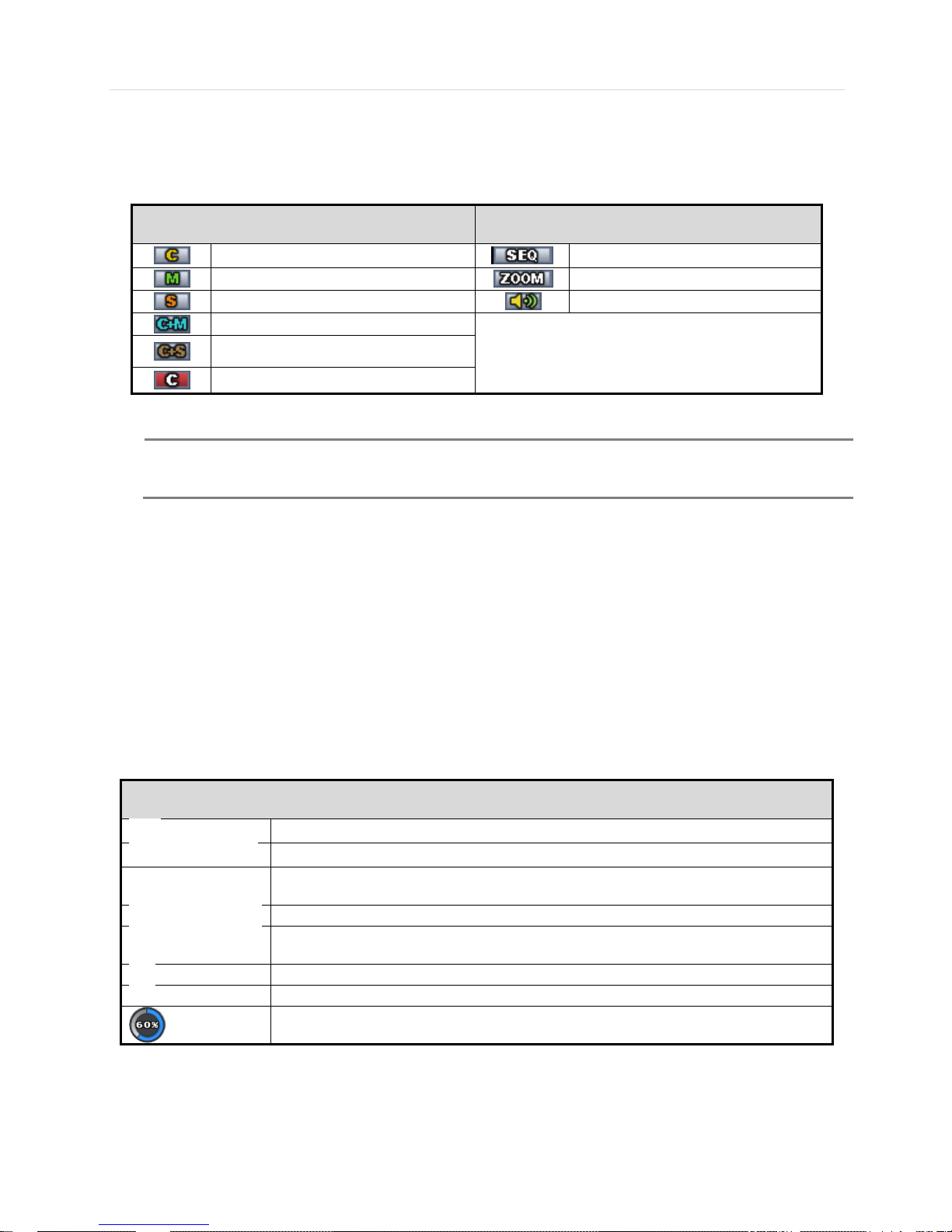
3.2.3 Icons
The live mode display’s icons or messages will be indicated on the screen to indicate the system mode or status.
Below are the icon categories that are indicated on the monitor:
Icon to be shown
at Left-upper corner on each channel screen
Icon to be shown
at Left-bottom corner on full screen.
Continuous Recording
Sequence display on
Motion Detection Recording
Digital zoom on
Sensor Activating Recording
Audio Channel
Continuous+ Motion Recording
Continuous + Sensor Activating
Recording
Emergency Recording
NOTE
If you cannot find any colored-mark in the top right corner of the live screen mode, then it means that the
system does not record any image. In this case, you need to check recording schedule or camera of the
main setup menu.
The sliding menu for display will be appeared when mouse cursor move into bottom and right click of mouse enale to access
pop-up menu.
To show the menu bar, move the mouse’s cursor to
the bottom of the screen. The menu bar will be
displayed.
To hide the menu bar, move the mouse’s cursor
away from the menu bar.
Menu Bar
Menu button. When pressed, System Setup, Search, Backup, Logout will appear.
Screen split options- Select from single channel, 4 channel, 9 channel, or 16 channel display.
Sequence- if pressed, the system will start displaying all the channels in sequence mode.
To stop, press the button again, or right click on the screen and select ‘SEQUENCE’
CH. Buttons- view a specifc channel in full screen mode.
Instant (emergency) recording- The system will record video based on the panic record
settings.
PTZ mode- Control any supported PTZ cameras by moving the mouse pointer.
Go to Instant playback.
HDD usage indicator- Indicates the percentage of your HDD being used. If it shows 60%,
then 60% of HDD space has been used.
Page 20

User’s Manual | 20
3.2.4 Pop-up Menu
User can click the right button of the mouse to pop up sub-menu as shown below.
DISPLAY- Select the display split from the available options:
- 1 Screen- Single channel. Automatically displays CH1. If 1 Screen is selected again, next chronological channel will be
displayed.
- 4 Screen- Quad mode. Automatically displays channels 1~4. If 4 Screen is selected again, the next chronological 4
channels (5~8) will be displayed.
- 9 Screen- Automatically displayes channels 1~9. If 9 Screen is selected again, the next cohoronological channels
(10~16+1~2) will be displayed.
- 16 Screen- Displays all 16 channels (available only in 16 channel models)
PTZ CONTROL- Open the DVR’s PTZ control. See section 3.3 PTZ for more information.
SEQUENCE On/Off- when selected, icon will appear on the bottom right corner of the screen, and the display
screen will be sequentially changed.
Please note, option will be disabled if display area is in Max channel mode.
Spot out Monitor- Enter Spot out Monitor Control Mode.
ZOOM- Enables/ disables digital zoom function with x2, x4, x8 button. When enabled, icon will appear and
zoomed area will be displayed on the bottom right corne. The Zoom will automatical y focus on the center of the camera’s
display. To adjust ot, go to the small zoom display at the bottom of the camera display and move the yellow frame to the
desired are you would like to view in zoom. To move the yellow frame, use your mouse to drag the lines of the yellow frame to
the desired location. To go back to live display mode, right-click on the screen and select “ZOOM” again. This feature is
available in single channel mode only.
INSTANT REC On/Off- Start/ Stop Panic Recording.
PLAYBACK- Select playback option:
- 10, 15, 30, 60 seconds- start playback from the selected number of seconds ago.
- 2, 3, 5, minutes- start playback from the selected number of minutes ago.
- Open Playback Mode- automatically go to instant playback.
SEARCH- Select video search options:
- Date/ Time- open calendar search.
- First/ Last Data- Go to the first or last recorded data.
- System/ Event Log- open log search window.
- Bookmarks- open bookmark search.
Backup - Users can archive a video clip recorded for a certain period on a selected channel.
SETUP- open the DVR’s main menu.
Page 21

21 | Full HD Digital Video Recorder
SHUT DOWN- Power off the DVR.
LOGOUT- User logout.
As the Admin user, you can seup up multiple users with different levels of authorization. If a certain user is not allowed to view
a certain camera in live or playback, then no image will appear on the display screen. To create, delete, or modify users, go to
the main menu and select system settings. See section 4.1.2 User for more information.
Page 22

User’s Manual | 22
3.3 PTZ Operation
Before starting PTZ control, please make sure the camera you wish to control is a supported PTZ camera and is installed and
configured properly. See section 4.2.6 PTZ for setup information. To enter PTZ mode, follow one of the options below:
1. Right-click on the screen and select PTZ Control.
2. Click on the joystick button in the menu bar located on the bottom of the main screen.
3. Press the PTZ button on the front key.(enable front key model)
4. Also to use UTC click the button, the camera menu display on the full screen. And user move button menu
by up/down, left/right button change the setting. Enter is select menu.
In PTZ mode, user can control PTZ operation with the USB mouse.
While pressing the left button of the mouse, drag the mouse pointer up/down, left/right to move pan/tilt position of the camera
accordingly. The further away from the center of the screen you move the mouse, faster will the camera move. The user can
also zoom-in/out by rolling the wheel of mouse up or down.
NOTE
Full PTZ functions are available by using USB mouse, or keyboard controller and are available only on
supported PTZ cameras.
For focus control in PTZ mode, right-click to get the pop-up menu as shown below. Default mode is to “ZOOM”. Select
“FOCUS” to switch the mouse’s wheel function from zoom-in/out to focus near/ far.
The user can also select the preset button to start/ stop a preset, or exit PTZ screen model.
NOTE
User will see numeric pad to select “Preset” number. The preset is defined by setting a PTZ protocol in
Page 23
23 | Full HD Digital Video Recorder
the setting menu. The maximum number of preset is 255, but the number of available presets may vary
by camera make and model.
User can automatically switch PTZ camera positions according to defined presets by using the GUARD TOUR function. The
connected PTZ camera must support touring functions. “GUARD TOUR” on the pop-up menu can be enabled only in full
screen mode. See 4.2.6 PTZ for instructions on how to setup the GUARD TOUR.
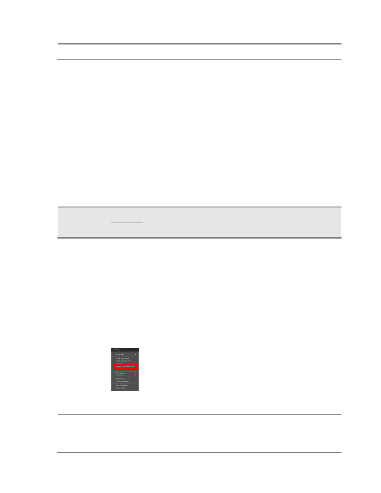
3.4 Spot out Monitor
Click the right button on the mouse and select the Spot out MONITOR in order to enter call monitor control mode. The
numeric panel will pop up at the center of the screen.
Click the specific channel button on the numeric panel to display full screen mode out of assigned spot out channels.
▪ Press the close button on the bottom of the numeric panel. It will go back to the previously programmed spot monitor mode.
NOTE
- A spot out monitor displays another spot out monitor’s video in full screen through the function, spot out
monitor.
- In spot sequence setting mode, if spot out monitor is selected, spot sequence stops and selected
channel pops up.
- While call monitor runs, if a channel event happens, spot out monitor stops and the event pops up.
CAUTION
Depending on PTZ camera, some preset positions might be skipped if, for example, the PTZ camera
cannot mechanically move or control focus within the interval time required by the DVR. In this case,
it is recommended to increase the interval setting to a value that allows for the cameras to finish its
Pan & Tilt.
Page 24

User’s Manual | 24
3.5 Playback of Recorded Video
To play a recorded video, press the Play button from the menu bar, or the Instant Play in the DVR’s front panel(Front key
type)
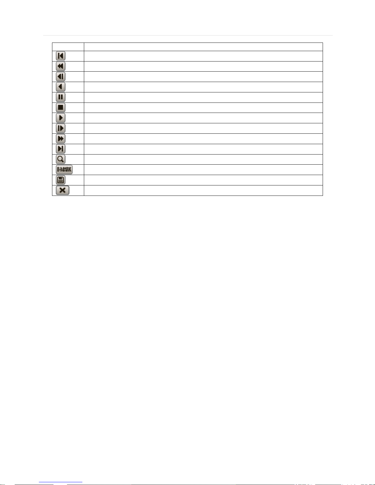
The recorded files can be seen in rewind or fast forward modes. Press the rewind and fast-forward buttons to control the
playback’s speed ( 2, 4, 8, 16, 32 times real time when playing backwards or forwards).
User can click playback button to automatically play the latest video clip in rewind mode.
The picture below shows the system playing back a video.
In playback screen, user can make various playback modes, make an instant manual backup (archive), go to calendar
search mode, change channel, and change screen modes. By clicking the left mouse button in the colored-time bar, the user
can jump to a different time in the recording. In addition, user can move the vertical search bar and release by dragging it
back and forth to search the desired time in detail.
Page 25
25 | Full HD Digital Video Recorder
Button
Function
Jump to first data. If recording is set to motion, system will jump to previous recorded motion video.
Fast rewind
Frame-by-Frame Rewind
Play video in rewind
Pause video
Exit Playback to Live mode.
Playback video
Frame-by Frame playback
Fast playback
Jump to last data. If recording is set to motion, system will jump to the next recorded motion video.
Go to calendar search
Bookmark Video
Backup
Exit Playback to Live mode.
Page 26
User’s Manual | 26
3.6 Search Recording Image
3.6.1 Date/Time Search
To search your recorded data by date/ time, follow one of the options below:
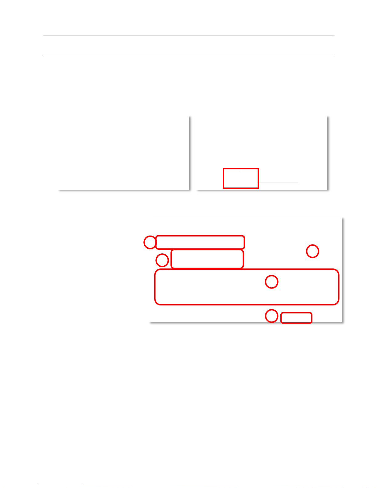
1. Click the quick Menu button at the left side of the menu bar, select Search Date/ Time
2. Right-click anywhere on the screen, select Search Date/ Time
The calendar window will appear, Days with recorded data available will be indicated in RED.
1. Select from the calendar the date.
If necessary, use the manual year
and month options on the left side
to adjust the calendar view.
2. The ‘Intelli-Search Bar’ at the
bottom of the window will display
hours when recorde data is
availablein color code. Once the
recorded video data of the
selected date is shown, user can
adjust the vertical search line to
the time that user wants to search
by dragging a mouse. As the
vertical line is moving back and
forth, user can see “the Search
time” clock is also changing.
When user decides the Search
time, click Play to see the
selected video data.
3. The colors of the time bar are different, depending on the recording mode.
No color - NONE- Camera has no recorded data for the selected time.
Red- Panic recording- recording triggered by the user when pressing the Instant/ Panic Recoreding.
Yellow- Continuous recording.
Green- Motion recording- The system records only when motion is detected.
Orange- Sensor recording- The system records when a sensor is triggered and only during the dwell time as set in
“SENSOR” of the “DEVICE” menu. If “SENSOR” is disabled under the “DEVICE” menu, and recording
schedule is set to “SENSOR”, the system will not record even though a sensor is triggered.
Blue- “Continuous” + “Motion”-The system records continuously and will switch to the motion recording configuration
if motion is detected in the motion area. The system will also send a “motion event” message to the Central
Monitoriong Software over the network. If “MOTION ALARM” is disabled in the “DEVICE” menu, and
recording is set to “CONT + MOT”, the system will record with continuous recording even when motion is
detected in motion area.
Orange- “Continuous” + “Sensor”- The system records continuously and will switch sensor recording if a sensor is
1 2 3
4
5
Page 27
27 | Full HD Digital Video Recorder
triggered during dwell time. The system will also send a “sensor event” message to the Central Monitoring
Software over the network. If “SENSOR” is disabled in the “DEVICE” menu, and recording mdoe is set to
“CONT + SENS”, the system will record with continuous recording even when a sensor is triggered.
4. To view video from the selected time, follow one of the options below:
a. Use the manual hour option to view specific hours of the day.
b. Using the table, click on the hour you would like to view in playback.
5. Press the ‘Play’ button at the bottom fo the window. The system will display all channels in playback mode,
corresponding to the selected date and time.
3.6.2 Event Log
The Event log search allows you to search for a particular event, quickly and easily, displaying the search results in a detailed
table format.
1. To open Event Log Search, perform one of the following options:
a. Click quick menu button, select Search Event Log
b. Right-click anywhere on the screen ans select Search Event Log.
2. Select the date you would like to search.
3. Select which events should be included in the log report. Select from: Sensor, Motion, Video Loss, Panic Recording,
HDD Full, or All.
4. Press ‘Search’. The system will display all search results in the table, starting with the latest events.
5. Use the buttons on the bottom of the window to move between the log report’s pages.
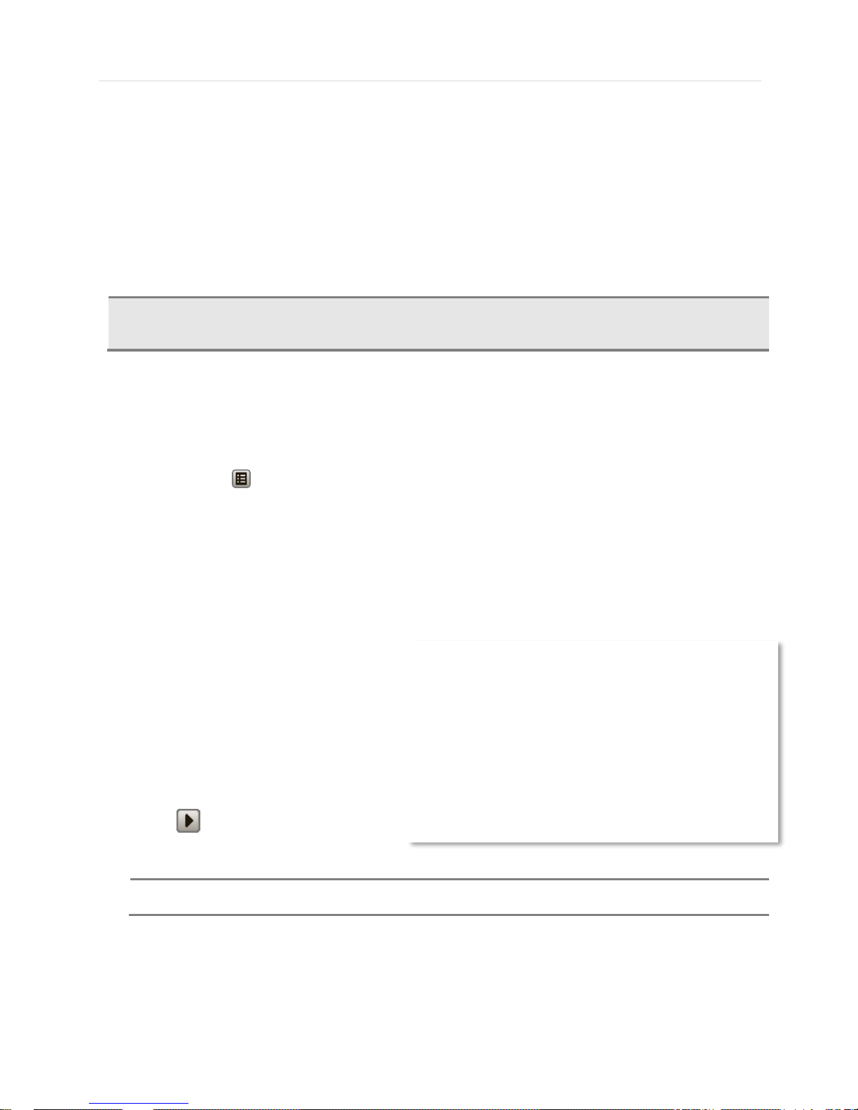
6. If necessary, export this log report to a USB
memory device in text file format.
a. Attach a USB memory stick to the
USB port
b. Press “SCAN” to detect the USB
stick
c. Press “EXPORT” to copy the log
information to the media.
7. Click play icon to play back the selected
event data.
NOTE
If an alarm or event do not appear in the envent log, check the alarm settings, and connection port at the
DVR’s rear panel.
CAUTION
Dark Blue Color
The data recorded during DST (Daylight Saving Time) will be indicated in Dark Blue color in the IntelliSearch Bar on playback mode.
Page 28

User’s Manual | 28
3.6.3 System Log
The system log search allows you to search for any changes made to the system, quickly and easily, displaying the search
results in a detailed table format.
8. To open System Log Search, perform one of the following options:
a. Click quick menu button, select Search System Log
b. Right-click anywhere on the screen ans select Search System Log.
9. Select the date you would like to search.
10. Select which events should be included in the log report. Select from: System, Setup, Network, or All
11. Press ‘Search’. The system will display all search results in the table, starting with the latest events.
12. Use the buttons on the bottom of the window to move between the log report’s pages.
13. If necessary, export this log report to a USB memory device in text file format.
a. Attach a USB memory stick to the USB port
b. Press “SCAN” to detect the USB stick
c. Press “EXPORT” to copy the log information to the media.
Once export is completed, the user can find a date folder created in USB thumb drive.
There is “system.log” file stored in the date folder.
Page 29
29 | Full HD Digital Video Recorder
NOTE
9 numbers of log record will be shown on one page of the <System Log> and <Event Log> window. User
can click the arrow icon to search the log records on another page.
3.6.4 First Data
Go to the first screen of the recorded video. This is the oldest video recorded.
3.6.5 Last Data
Go to the last screen of the recorded video. This is the latest video recorded.
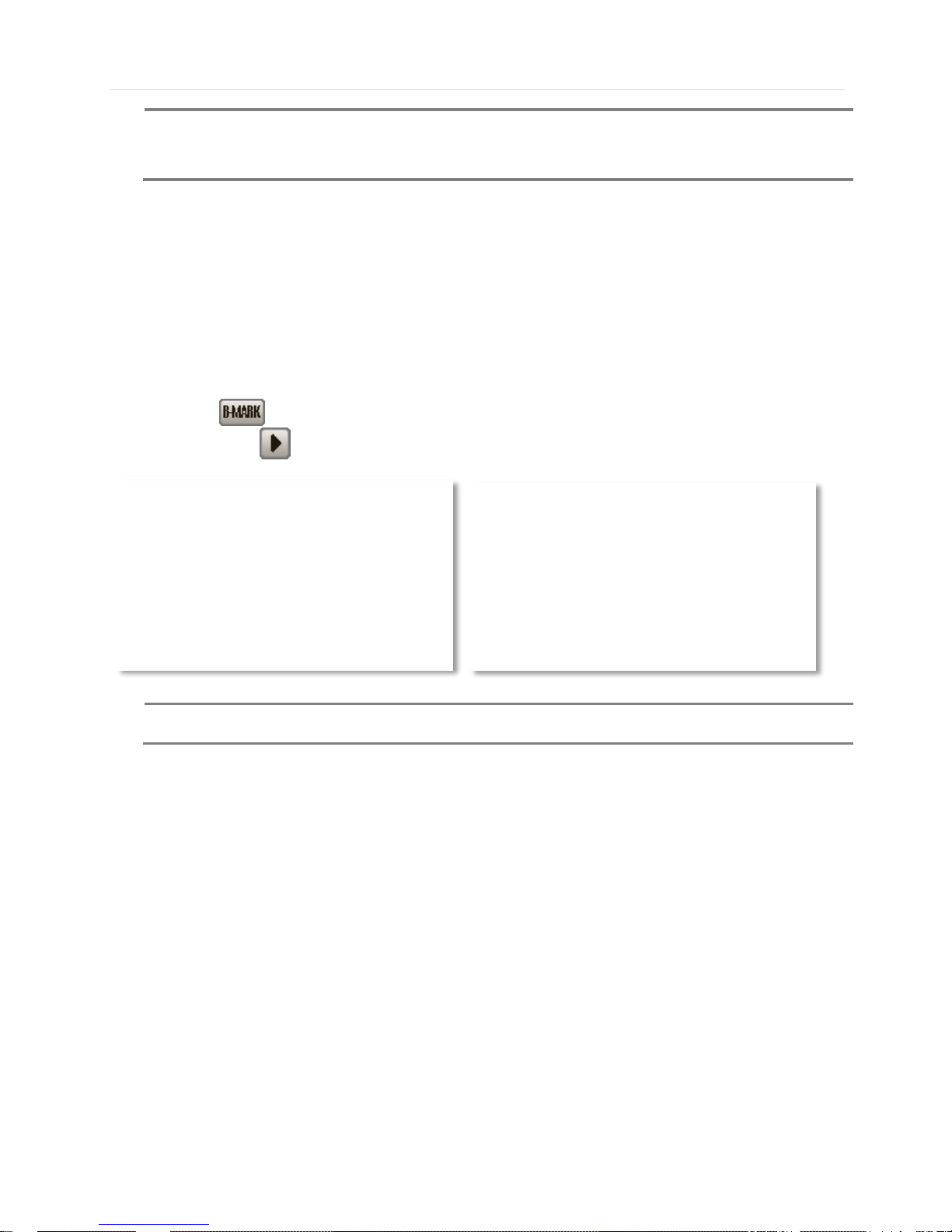
3.6.6 Bookmark
Go to the bookmark list to search the recorded video data in the bookmark list. Users can make their own bookmark list very
simply by click button, during playback. When you do bookmark search, you can easily playback the bookmarked
video data by clicking button, right next to each list.
NOTE
User can press “SEARCH” button on the front panel to get the SEARCH pop-up menu as shown above.
In this menu, full search functionality is controlled using the front panel key buttons(Front Key type)
Page 30

User’s Manual | 30
3.7 DST Setting
DST starts at 2:00 local time on 2nd Sunday of March, and ends at 2:00 DST on 1st Sunday of November.
During DST (Daylight Saving Time) period, DVR time clock has to be adjusted according to regional time zone. That is, the
DVR time clock will be shifted by one hour after the DST settings start, and the DVR will restore the time clock back to normal
after DST finishes.
To make DST setting on the DVR, go to the menu: SYSTEM > SYSTEM INFO and click “DATE/TIME” to get the DST setting
window as shown below. User can setup DST “Begin & End” time after checking “USE DST” box.
Since the clock jumps from 2:00 to 3:00, when you go to search mode, you can clearly see there is no data in all channels for
one hour due to DST.
DST ends at 2:00 DST, and the clock jumps backward to 1:00 standard time on 1st Sunday of November.
When DST finishes, there is an hour of overlapped video. The overlapped time video will be indicated in a blue color in the
Intelli-Search Bar during playback mode.
Page 31

31 | Full HD Digital Video Recorder
When user click on such overlapped period, a message titled “Recorded video Selection” will pop up. The user can then
select whether to play DST data or Non-DST data.
Click OK to play DST image. Click CANCEL to play Non-DST image.
[“DST” image is displayed on screen] [“Non-DST” image is displayed on screen]
3.8 Screen Saver
To make SCREEN SAVER setting on the DVR, go to the menu setup: SYSTEM > SYSTEM INFO and click “SCREEN
SAVER” to get the SCREEN SAVER setting window as shown below. Users can select HD output by checking the boxes.
Users can set the WAITING TIME for when the monitor will automatically turn off.
Users can turn on the selected monitor by clicking a mouse, pressing any frontal key buttons
NOTE
WAITING TIME: Users can select the WAITING TIME from NONE, 1,2,3,4,5,6,7,8,9,10,20,30,40,50, and
up to 60 MIN. The SCREEN SAVER will not work when either WAITING TIME is set to “NONE”.
SCREEN SAVER may not work, during system upgrade, HDD format, or data backup process. The
system continues to record while the monitor is turned off.
When it comes to the “AUTO LOGOFF” setting, please refer to the USER setting.
Page 32
User’s Manual | 32
4 SETTING
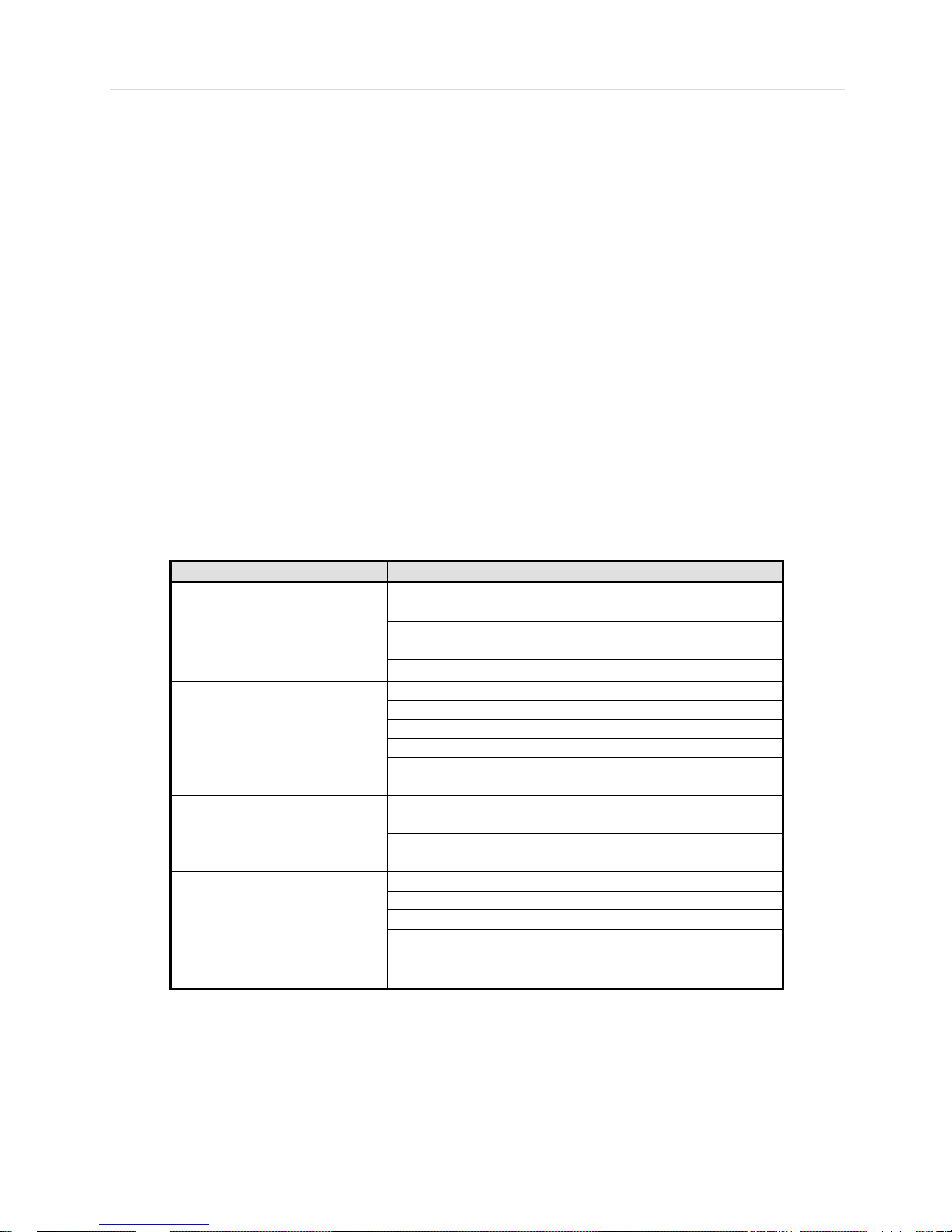
General setting structure consists of “System”, “Device”, “Record”, “Network”, “Backup,” and ‘Quick Setup” as shown below.
<SYSTEM> <DEVICE> <RECORD>
<NETWORK> <BACKUP> <Q-SETUP>
Main Classification
Sub Classification
SYSTEM
SYSTEM INFO
USER
EXPORT/IMPORT
HDD
FACTORY DEFAULT
DEVICE
CAMERA
AUDIO
SENSOR
MOTION ALARM
EXTRA ALARM
UTC/PTZ
RECORD
RECORD SETUP
PANIC RECORD
SCHEDULE
HOLIDAY
NETWORK
NETWORK
DDNS
NOTIFICATION
HEALTH CHECK
BACKUP
BACKUP
Q.SETUP
QUICK SETUP
Page 33

33 | Full HD Digital Video Recorder
4.1 System
The system menu button is selected by clicking “TOOL” on the menu bar or clicking the right mouse button.
Users can move mouse pointer from “System” through “Quick Setup” to instantly look around the sub-menus on the menu
screen. Using the left mouse button, the user can select a desired category for editing.
4.1.1 System Info
The System Info sub-menu includes the following setup options: Date/ Time, HD Resolution, Language, Remote ID, Version
& System Upgrade, Video Signal, IP & MAC Addresses, Keyboard Setup, NTP Setup, Display Setup, and Screen Saver
Setup.
Page 34

User’s Manual | 34
- Date/ Time- manually enter the DVR’s date and time,
time zone, and enable/ disabled DST.
Using the available options, manually adjust the date
and time from the calendar, select the display mode for
the time, and the date, and select the appropriate time
zone. If applicable, check the ‘USE DST’ box. See
section 3.7 DST Setting for more information.
- HD Resolution- Select the DVR’s output resolution.
DVRs support the following video resolutions:
1024x768, 1280x1024, 1920x1080, , 3840x2160(4K no
support 4ch model.)
User must set the proper resolution according to the monitor resolution
- Language- Select the DVR’s display language from the availanle in the drop-down menu.
- Remote ID- Set the DVR’s remote ID. This ID should be the same as the IR Remote Control.
- Firmware Version & system upgrade- when a new version is available, use the easy upgrade menu to upgrade your
DVR to the latest version. To upgrade your system, follow one of the options below:
Upgrading system using USB memory stick:
1. Insert the USB thumb-drive formatted by FAT32 in any USB port of DVR (compatible with USB 2.0)
2. Once the system detects the thumb-drive, user can see its brand or model name in the “DEVICE” field after
pressing the “SCAN” button.
3. Click “OK” to confirm.
Upgrading system using FTP server:
1. Select FTP in the drop-down list and type a given IP address in the Host Address . Username and password
is “upgrade” (Default).
*The FTP server address is subject to change without a prior notice.
2. Click ‘Check’ button then DVR will detect the latest Firmware version from the FTP server. If there is a new
firmware, DVR will ask you whether you want to upgrade it or not.
3. Click ‘OK’ to confirm it and then click ‘START’
to start upgrading.
CAUTION
It is recommended to format the HDD after finishing the firmware upgrade because the data recorded
by previous firmware may cause malfunction of DVR due to different format.
It is highly recommended to check all functions and menus after a firmware upgrade for proper layout
and performance. If necessary, you can return system to its default settings.
- Video Signal- Displays the video input signal from the DVR.
- DVR’s IP & MAC Addresses- This information is necessary when connecting to the DVR via its web viewer or the
Central Monitoring Software. See section 4.4 Network for more information and configuration options.
- Keyboard setup- Setup the DVR’s ID, baudrate and model to match the information of the keyboard you would like to
use. The Keyboard’s ID must match the ID set in the DVR.
Page 35

35 | Full HD Digital Video Recorder
- NTP Setup- Setup the DVR to automatically sync with a Network Time Protocol.
There are two types of TIME SYNC MODE:
o Client Mode- The operating DVR is set as the client
DVR. Enter the IP address or URL of another DVR
or Central Management Software (CMS), as a
Time Sync Server in “SYNC SERVER”. This will
cause your DVR to sync its time with a Time Sync
Server in the set interval time.
- Display Options- Set sequence dwell time, pop-up camera,
and OSD as indicated below:
o OSD:
Select which information will be displayed in the OSD visible on each channel in Live.
Select which information will be displayed in the OSD visible on each channel in Playback.
Set the OSD’s transparency level, the higher the percentage, the more transparent the OSD text
will appear.
Setup a dwell time for the OSD text, after which, the OSD will automatically disappear.
Setup a dwell time for the Setup Menu, after which, the Setup Menu will automatically disappear.
o Set sequence dwell time- Setup how long the system will display each channel in Sequence mode, before
switching to the next channel.
o You may select On/Off for Live or Playback status display by checking a check box.
- Screen Saver Setup- See section 3.8 Screen Saver for more information.
Page 36

User’s Manual | 36
4.1.2 User
Master user of this system is always Admin with factory default of No password. This user cannot be deleted.
It is recommended that the Admin change the password for extra security.
Admin can designate a new user with different permission levels by: functions, menu access, and live & playback.
“Function” options restrict a user’s access to functions such as search, PTZ control, backup, and playback.
“Menu Access” options restrict a user’s access certain menu settings. Such as system, device, record, network, backup, and
quick setup.
“Covert” options restrict a user’s viewing of the deselected channels. If a channel is deselected, user will not be able to view
live or playback for thet certain camera channel
User can change the setting, so the DVR does not require login or lock the DVR control.
If user selects “On Boot”, the DVR will not ask for an ID and Password input again even though the system reboots.
On the contrary, if user selects Auto Log-off and sets the time, the DVR will automatically go to the live display mode that
occurs after the set time. Then, the DVR will ask for an ID and Password input when user wants to control the DVR.
NOTE
Total number of users including administrator is 9 users.
Page 37

37 | Full HD Digital Video Recorder
4.1.3 Export/Import
Users can copy and paste the system configuration values in this menu. “Export” allows the user to copy the settings for this
system to USB memory devices. “Import” allows the user to recall the settings saved from other systems using USB memory
devices. During import process, make sure that the firmware version of source DVR is the same as the destination DVR.
4.1.4 HDD
HDD information sub-menu displays all relevant information regarding all HDDs connected to the DVR.
Press the ‘Check’ button next to the HDD’s name to view that HDD’s health status. When pressed, the system will display:
Model: Make and model name of the Hard Drive.
Size: Total size of the Hard Drive, in KB.
Temperature: Hard Drive’s current Temperature, displayed in Celsius. Normal operating temperatures should be between 30°
and 45° degrees.
Live Time: Remaining estimated hours of operation.
Bad Sector: any unusable areas in the HDD that may affect recording, displayed in percentage of the total HDD.
User can select “Overwrite” or “Rec Stop” when the HDD is full. If ‘Overwrite’ is selected, when the HDD is full, new video will
be recorded OVER older data. If ‘Rec Stop’ is selected, the HDD will stop recording any data once it’s full.
To format a new HDD or an existing HDD, check the checkbox next to the HDD you would like to format, and click “HDD
Clear”
If system resources are occupied with task, such as making a network connection or performing video playback during the
format process, the format may fail. If the format fails, reboot the system resources and then try to format again.
NOTE
1) Formatting may take around 40 sec for 320GB, 1 minutes for 500GB, or 7 minutes for 2TB.
2) The system always reserves a maximum of 20GB of space in each built-in HDD to utilize the memory
for archiving effectively.
3) Available 2 HDDs installation on 2 HDD CASE models only.
Page 38

User’s Manual | 38
4.1.5 Factory Default
With an authorized password, users can get the system back to factory default configuration.
NOTE
Upon clicking “Start” button and entering the admin password, all the configuration values made by the
user will be deleted. The system setting will be sent to factory defaults. The recorded video data will not
be erased.
Page 39

39 | Full HD Digital Video Recorder
4.2 Device
There are sub menus in the Device menu, such as Camera, Audio, Sensor, Motion Alarm, Extra Alarm, and PTZ.
Users can easily move to the “Device” menu by selecting the icon on the top right of the menu screen.
4.2.1 Camera
Users can setup camera title, brightness, contrast, motion sensitivity, and audio mapping for each camera.
The default motion area setup is the entire camera area.
Audio mapping is Applies a user specified channel to audio connection.
Automatically detect the cameras such as 3M, TVI, HDA(Analog HD) and 960H. (Set Video Type as AUTO)
Most type of camera is automatically apply 3M, TVI, HDA, 960H
TVI : In case of TVI camera disconnect, Please set it manually
HDA : In case of HDA camera disconnect, Please set it manually
CVI : In case of CVI camera, please set ‘CVI’ manually
NOTE
When Auto detection is not working well under improper environment,
select type of camera directly on Video Type.
Page 40

User’s Manual | 40
4.2.2 Audio
Users can select the audio input and output during live display and match the audio input to a designated channel. (Please
refer to Section 4.3.1 Camera Record).
In addition, users can listen to the audio for both live display and playback mode through the network using Central
Management Software (CMS), or Internet Explorer web browser.
4.2.3 Sensor
Type- OFF, N/O (Normal Open) , N/C (Normal Close) The Sensor.
Cam- Select the associated camera.
Notify- Users can select how to be alerted when a sensor is activated or motion is triggered by pressing the
“NOTIFY” button. The system can generate a buzzer sound and/or make a pop-up screen for the camera in
alarm.
CAUTION
Relay contact can handle up to 24VDC/1A(or 125VAC/0.5A) of other devices. If connected to a circuit
that is over 24VDC/1A(or 125VAC/0.5A), the system may experience problems.
Page 41

41 | Full HD Digital Video Recorder
Preset- User can select the camera to move to a preset position, once the sensor is triggered. (User should
setup preset position in PTZ menu 4.2.6 in advance). In addition, users can set multi-preset with a single PTZ
camera. Therefore, users can cover a multi-preset zone with a single PTZ camera.
Relay- 1 /Off Relay Output.
Dwell Time- Set the recording period from the start of sensor input activation. During this period, the
corresponding camera video will record according to the frame and alarm (relay) output set. The recording
stops and alarm output is turned off when the dwell time has elapsed.
NOTE
“Sensor” here means the alarm connected to the DVR, which is triggered by physical sensor input.
NOTE
If the sensor does not operate properly check the setting of the sensor type (N/O or N/C).
The alarm might not function if the actual connecting sensor type and the sensor type in the system
setting are inconsistent.
NOTE
“Camera pop-up” means that multi-screen live video mode will be switched automatically to single
channel mode, when an alarm is triggered. This single channel video will be the channel triggered by
alarm.
Page 42

User’s Manual | 42
4.2.4 Motion Alarm
Select Motion alarm to record only when motion detection is triggered by DVR S/W upon user’s defined motion area.
An alarm signal is sent via the selected sensor-out channel.
COPY SETTINGS
Upon pressing Copy Settings button, Copy Settings popup will appear. In this popup, choose the camera the
user wants to copy from at the “From” field. Choose the parameters such as Use, Notify, Relay, and Dwell Time
on the check box. Check on the checkbox next to the sensor numbers to apply the copy setting(s) to another
channel on the “To” box.
4.2.5 Extra Alarm
S.M.A.R.T. alarm is an alarm signal triggered when the HDD is about to be out of operation.
This alarm is created by the HDD and captured by DVR. If the HDD does not create this alarm, then the DVR also cannot
capture and output this signal.
If user set the No disk and Video Loss, when HDD has not equipped or unrecognized and video loss the system will
notify with a beep sound.
Users also set the percentage for HDD Usage. For example, when Usage is 50%, DVR will notify by a camera popup or a
beep sound when HDD is 50% full.
NOTE
“Motion Alarm” here means alarm triggered by motion detection set by motion menu of DVR.
Page 43

43 | Full HD Digital Video Recorder
4.2.6 UTC/PTZ
1) Connect PTZ
Full control and setup of supported PTZ cameras is available in this menu. For more information on controlling PTZ cameras
in live mode, see section 3.3 PTZ. Use this setup menu to setup a PTZ camera, adjust the camera’s zoom, focus and iris (on
supported models), adjust the pan, tilt and zoom control speed, or setup presets pan, tour and guard schedules.
Adding a PTZ camera: Once a PTZ camera is properly connected to the DVR using the RS485 ports, go to the PTZ setup
menu and adjust the following values:
Protocol- Select the proper protocol of the connected PTZ camera from the supported drop down menu options.
HD-A / HD-TVI : In case of Menu-Enter is works preset 95 or IRIS, the connection is auto detected.
HD-A(C) : Some of HDA camera which non-detected on the HD-A / HD-TVI, apply this protocol
HD-TVI(C) : Some of TVI camera which non-detected on the HD-A / HD-TVI, apply this protocol
Address- Set the PTZ driver address of the connected camera. This address must match the PTZ’s address.
Baud rate- User can select the baud rate level from 1,200bps up to 115,200bps.
Troubleshooting- if the camera is unresponsive, check the following:
1. The protocol of the PTZ camera is correct and matches the one selected on the DVR.
2. The communication settings, including the baud rate, of the PTZ camera are in accordance with the assigned values
on the DVR.
3. The address of the PTZ camera is correct and matches the one selected on the DVR.
4. The wiring to the PTZ controllers are correct and the cables are intact.
2) PTZ set up
Controlling a PTZ camera: To check the ‘USE PTZ MENU’ mode on the UTC/PTZ tab. Once the camera is properly
connected and configured, use the following setting options as needed:
Zoom, Focus and Iris- on supported models, use the + and –to adjust the camera’s lens.
Directional arrows- use these arrows to move the camera to a desired position or control the camera’s OSD menu (on
supported models).
Pan, Tilt and Zoom speed- Use the bars for each option to adjust the control speed. The higher the number, the more
sensitive the camera will be to control commands from the DVR, and move faster.
Page 44
User’s Manual | 44
PTZ Control mode
If check the Continuous, The command is entered in quick succession
Control any supported PTZ cameras by moving the mouse pointer.
Focus
Iris Select the preset number and ‘Set’ button, ‘Move’ button is move to setting area
Activate the PTZ menu
Enter
Zoom In/Out
1) UTC set up
UTC is remotely set to camera OSD menu in the DVR. Select the proper protocol of the connected camera. Non-check
the ‘USE PTZ MENU’ mode, set the menu and adjust as below.
Menu : Activate the camera OSD menu for setup and adjust
Up/Down arrow : move to categories
Right/Left arrow : Adjust the camera settings
Enter : Select the camera settings or enter the subcategories
2) To use UTC in the Live Mode
Select the single channel which adjust the camera set and change the PTZ Control mode.
Click the right button of mouse and select PTZ menu for activating UTC
click the button, the camera menu display on the full screen. And user move button menu by up/down, left/right
button change the setting. Enter is select menu.
Page 45

45 | Full HD Digital Video Recorder
4.3 Record
Users can configure various record settings such as Continuous, Event, and Panic for each individual camera channel in the
Record Setup Menu. Network Stream settings are independently configured from the Record settings in this menu as well.
Therefore, the user can optimize the bandwidth used by configuring the resolution, FPS, and image quality separately.
4.3.1 Record Setup
1. Locate RECORD icon from the main menu.
2. On the Record window Click on Record Setup tab.
3. Choose the desired resolution, frame rate, quality and recording type for continuous recording.
4. Choose the desired frame rate, quality and recording type for Event recording.
5. Configured each channel separately, or use the copy settings button to apply one channel’s settings to multiple channels.
NOTE
COPY SETTINGS- Copy Settings popup allows you to choose the camera you want to copy from in the
“FROM” field. Choose which settings you want to copy, such as Resolution, FPS, Quality, Event FPS, Event
Quality, PreAlarm and PostAlarm. Check the checkbox next to the cameras to apply the copy setting(s) to
another channel on the “To ” box. channel on the “To” box.
2nd Stream- Setting the 2nd stream resolution.
Page 46

User’s Manual | 46
4.3.2 Panic Record
Users also have the option to configure Panic Record settings. The Panic Record setting is intended to be used under
emergency situations. You engage Panic recording by pressing the “Instant Record” button on the frontal keypad, or
clicking the icon from the control panel in live mode. It is highly recommended to use the maximum resolution, FPS, and
quality for this record type.
Panic Active
To prevent involuntary panic recording such as press the recoding button on the remote, this feature can be enabled/disabled
through this check box.
Page 47

47 | Full HD Digital Video Recorder
4.3.3 Schedule
You can set up the record schedule by applying a various record modes to each date and time. Simply select a record mode
by mouse and drag it to the desired date and time.
4.3.4 Holiday
Users can setup a specific day of a month or day of week as a holiday as shown below. Once holiday is selected, the
recording setup for those holidays will be affected by the schedule setting in the schedule.
Page 48

User’s Manual | 48
4.4 Network
4.4.1 Network
The system has built-in web server.
Network Type
Select network connect type. Select either LAN for fixed (Static) IP or DHCP for dynamic IP.
If DHCP is selected, click ‘IP DETECT’ button to detect IP address information.
Subnet Mask
Subnet Mask address classifies the subnet that the system belongs to. Standard address is 255.255.255.0. For more
information, please consult your network administrator or your internet service provider
Gateway
This is the IP address of the network router or gateway server. It is required when the user wants to connect through the
external router from the remote. For more information, please consult your network administrator or your internet provider
DNS Server
Enter the IP address of the Domain Name Server. There are two DNS settings. (The preferred DNS and the alternative DNS)
*You should enter the DNS Server information in order to use internet. (Provided by your ISP)
Network Port
Enter the port number to use when connecting locally or remotely, or to mobile phones or WebACS.
Enter the port number to use when connecting from the Web Browser.
UPnP (Universal Plug and Play) and Auto Private IP Setup (NAT Traversal)
UPnP stands for Universal Plug and Play, which is a relatively new technology that indicates a universal protocol for
widespread plug-and-play devices to ease the network implementation. When a PC and a DVR both installed the UPnP
function, the PC can automatically recognize the DVR in the same local area network. The advantage of this function is that a
PC can connect to the DVR directly by clicking on the icon representing the DVR in <My Network Places> folder as shown
below. The first five characters of the file name of a detected DVR is subject to a firmware version
DVR-04 DVR-05 DVR -06
Page 49

49 | Full HD Digital Video Recorder
Simply double click on the desired icon. Then, it will open an internet browser that connects to the DVR via the remote control
software as shown below. Please type in your User ID and Password to login and click ‘Connect’ button to connect.
Auto Private IP Setup (NAT Traversal)
The UPnP NAT Traversal function will help to automatically setup a router if the DVR connects to the internet via a router.
When a PC connects to a DVR, which is not in the same local area network, a real IPO address and corresponding port
number is required. However if the DVR is behind a router, the communication between the PC and the DVR will be
transmitted back and forth by the router. The router will need to setup port mapping (Port Forwarding) before images from the
DVR is remotely viewed on the PC. For each individual DVR, the setting needs to be done individually.
If the DVR has UPnP NAT traversal function, the setting of the router will be done automatically when it is enabled.
Just check ‘Auto IP (NAT Traversal)’ check box in the UPnP setup menu. Then it will take care of Auto IP detect by itself.
NOTE
The system transfers video images at real-time over the network even during no record.
For example, user can monitor live video even when motion has not occurred during motion detection
mode.
NOTE
If there is no physical network connection, it may take a few minutes for the system to start working, since
the network configuration in DHCP mode and the DHCP connection cannot be made.
Page 50

User’s Manual | 50
4.4.2 DDNS
The User has to mark the “Use DDNS” check box to use it.
DDNS Server
Joinip.net or joinip2.net is the fixed domain name of DDNS server
User cannot change the DDNS name.
NOTE
The standard DDNS domain name is joinip.net, and users can use joinip2.net or dyndns.com by dropdown list.
Page 51

51 | Full HD Digital Video Recorder
4.4.3 Notification
Remote Notify
The system can notify an alarm message to the IP address of Central Monitoring Software over the network.
User can choose from a selection of different kinds of alarms by pressing “ADD.” Alarms can be generated by Sensor,
Motion Detection, Disk Full, Admin PW Changed, Video Loss, and System Start.
Push Setup
Push notification setting
1. Check to “Remote Notify” and click “Push Setup” button
2. Check “Event Type”, “Channel”, “Time Schedule” for notification to Mobile app and CMS.
Page 52

User’s Manual | 52
E-Mail Notify
The system can send notification to an Email address the Central Monitoring Software over the network. User can choose
from a selection of different kinds of alarms by pressing “ADD.”
Alarms can be generated by Sensor, Motion Detection, Disk Full, Admin PW Changed, Video Loss, and System Start.
Interval ; Time interval for e-mail notification.
By clicking “Use SSL”, users can use a public email address such as Yahoo, Google, Hotmail accounts.
Type DVR name in the “DVR Name” box. The DVR name will appear in the email so that users can recognize which DVR
sent an email.
AVI image ; The standard extension of video back up file is PSF, If play the any video player, check this option and It will be
sent by E-mail.
NOTE
Configuration’s first priority is always given to “Schedule Setup ” of the “RECORD” menu.
Thus, the system will not send alarm message or email notification upon motion alarm or sensor even
though user marks the checkbox of above event selection, unless user sets the “Schedule Setup” in the
“RECORD” menu.
For example, if user sets “Continuous” only for “Schedule Setup ” of the “RECORD” menu and marks
the “All” checkbox in “REMOTE NOTIFY”, then the system will not send alarm messages. In this case,
user has to set “C + M”, “MOTION”, “SENSOR” or “C+ S” for REMOTE NOTIFY or E-Mail NOTIFY to
function properly.
Page 53

53 | Full HD Digital Video Recorder
4.4.7 Health Check
The DVR offers a uniquely true DVR health monitoring, with pop-up
messages and e-mail notification on video loss, recording failure, and HDD failure.
To setup:
1. Check the box next to "Enable Health Check"
2. Check the box next to the conditions you would like to be notified on.
3. Set the occurrence intervals.
(For Example: when video loss occurs more than1 time a minute)
4. Select whether to receive a popup message when conditions are met.
5. Go to Network Notifications.
6. Under e-mail notifications, make sure the Health Check option is enabled.
When any of the failures occur beyond the set conditions, the system will display a
popup alert and send an e-mail notification.
Page 54

User’s Manual | 54
4.5 Backup
4.5.1 Backup
Users can archive a video clip recorded for a certain period on a selected channel or channels as shown below.
Connect an appropriate USB memory device, like USB thumb drive, USB HDD, or a built-in CD or DVD burner and press
“SCAN” button to get the system to recognize it before archiving. Necessary file size will be shown before burning.
NOTE
Backup device shall be a well-known major brand of USB
thumb drives formatted by FAT/FAT32 for proper backup.
Please check the USB format type on the File system. It
must be set the FAT32
If user need to high-capacity memory format, Please use
the utility such as ‘USB disk storage format tool’ or ‘FAT 32
Formatter’
NOTE
User can click the “Calculate” button to learn the backup file size before executing backup.
NOTE
User can rename the backup file name before starting backup process and also put a password in the
backup file for security purpose. In order to playback the file, user should input the password.
Page 55

55 | Full HD Digital Video Recorder
4.5.1 Backup Video Retrieve
There will be a single file after archiving, if “Add Backup viewer” was selected.
User can double click “Player.exe” file to open the video data file (PSF format) in the folder.
User can print out, capture a still image, zoom out, or make an ASF file format, by using the icons located on top of the player
window.
NOTE
User also can play the backup-video clips by Central Monitoring Software.
Page 56

User’s Manual | 56
4.6 Quick Setup
Quick Setup helps user make simple configuration for recording resolution, entire recording speed by frame, recording mode,
and recording periods.
The system will put the first priority for configuration on this quick setup and will follow this rule regardless of configurations
set in other menus. Users should not fill in the checkbox of Use Quick Setup if he/she wants to utilize full system configuration
defined in the other menus.
NOTE
Quick setup must be deactivated if the user requires configuration from the other menus.
NOTE
After the user marks “Use Quick Setup” to define settings, the system will ignore all other configurations
set by full menus.
Page 57

57 | Full HD Digital Video Recorder
5 WEB SURVEILLANCE
The DVR has a built-in web server.
Using an ordinary web-browser over a network, users can always stay connected to the system for live monitoring, playback,
or remote configuration without installing any remote client software.
5.1 Web Login
The user is required to input the correct IP address in the web browser after making the web port available in the router.
Please note, if you are connecting to the DVR from a remote network (via the internet), you must port-forward the
corresponding ports in your reouter before you can access your DVR.
For more information, see the Appendix section, and consult your Installer or Internet Service Provider.
After allowing the download of the Active-X file, users can find the login page view seen below. Default USER ID is “admin”
and No password.
NOTE
Web ACS require to install Active X, Please use only IE
It is recommended to use an Internet Explorer web page.
To open the DVR’s web viewer on a Google Chrome web viewer, please install the IE Tab add on option.
Then, simply enter the DVR’s IP address or DDNS address in the address bar and click on the on the tool bar of
the web viewer.
Page 58
User’s Manual | 58
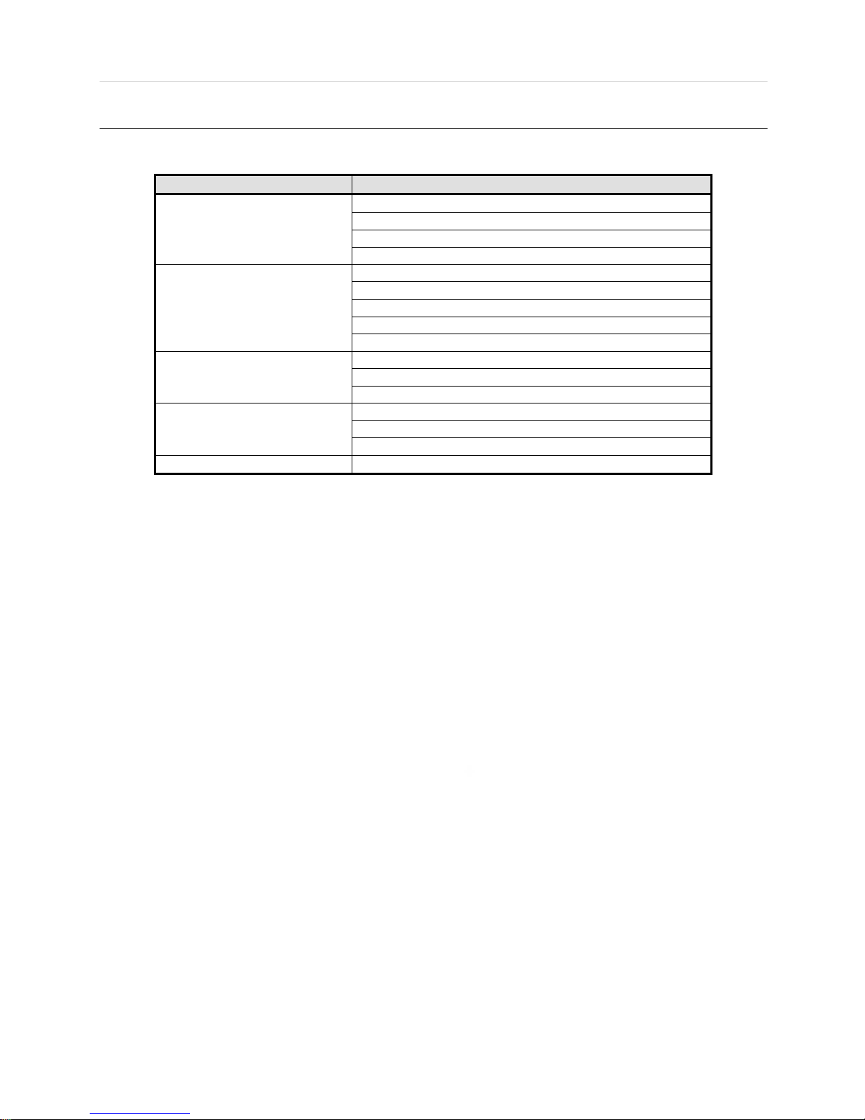
5.2 Web Configuration
Menu of Web Configuration
Main Classification
Sub Classification
SYSTEM
SYSTEM INFO
USER
HDD
DEFAULT
DEVICE
CAMERA
AUDIO
SENSOR
MOTION ALARM
EXTRA ALARM
RECORD
RECORD SETUP
PANIC RECORD
SCHEDULE
NETWORK
NETWORK
DDNS
NOTIFICATION
QUICK SETUP
QUICK SETUP
After logging in with the right ID and password, users can make various configuration changes in the Web Configuration
window seen below. This Web Configuration menu is only available to the “admin” account.
[System]
[Device]
Page 59

59 | Full HD Digital Video Recorder
[Record]
[Network]
[Quick Setup]
NOTE
This web CGI screen is directly supported from the built-in web server in the DVR, regardless of Internet
connection.
Page 60
User’s Manual | 60
5.3 Web monitoring
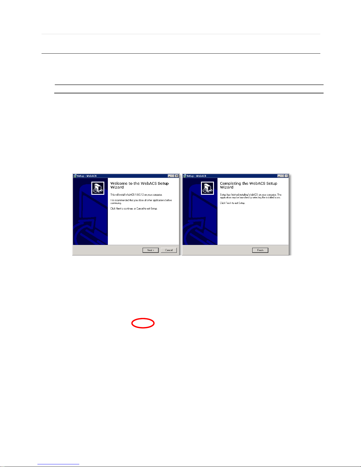
The first time you access your DVR via the Web viewer, you will be asked to install Active-X file before monitoring live video.
Please follow the installation process to complete the Active-X installation. Without it, you will not be able to view video from
any of the DVR’s channels.
NOTE
Web ACS require to install Active X, Please use only IE
[Web Active X Install ]
User can get into web monitoring after log in as shown below. In order to connect to DVR, the user has to click
“ Connect ” button which is located at the top left corner.
Page 61

61 | Full HD Digital Video Recorder
No.
Title
Function
1
Connection Mode
Select to view the DVR in Live or Playback Mode.
2
Connection Option
Select to Connect or Disconnect from the DVR.
3
PTZ
PTZ control options, including: virtual direction arrows, zoom and focus, and
preset.
4
Calendar
Date & Time search.
5
Playback Controllers
First data, fast rewind speed, play rewind, pause, play, fast forward speed, last
data.
6
Audio
Enable/ Disable audio.
7
Export Options
Export a still image, export a video, or print a still image with notes of a selected
channel.
8
Display Options
Select single, 4-channel mode, 9- channel mode, or 16-channel mode (16channel display will not be available on 8-channel models).
9
Channel Selection
Select manually a specific channel to go to single channel mode.
10
Time bar
In playback mode, indicates available recorded video for each channel for the
24 hours of the selected day.
11
Time indicator
Use the time indicator line to update playback video from a selected channel or
multi-channels.
12
Main Display Area
View live or playback from the selected cameras.
13
Remote Setup
Will open remote setup option (See 5.2 Web Configuration). Available for admin
users only.
14
Logout
Exit connection from the DVR.
①
②
③
④
⑤
⑥
⑦
⑧
⑨
⑩
⑪
⑫
⑬
⑭
Page 62
User’s Manual | 62
User can monitor live video in 1, 4, 9 or 16 screen modes. If user wants to see single channel in full screen, user can doubleclick on the left mouse button when the cursor is positioned on the live video screen. User can change to single mode by
clicking the mode icon located at the bottom left.
NOTE
If live image is not properly shown on IE web browser due to network traffic jam or narrow bandwidth, it is
recommended to close and re-open the IE web browser.
Page 63

63 | Full HD Digital Video Recorder
5.4 Web Playback
Users can remotely playback the DVR images by clicking “SEARCH” button in the middle of bottom window. In order to
connect to DVR, the user has to click “ Connect ” button which is located at the top left corner.
Playback Time
Select the date and time on Time Search, located at the middle of left side of window, and click button.
Playback Icon
Play/Pause is toggled and playback speed is shown on the left box.
Play DST
Check this box to play overlapped images during DST (Daylight Saving Time) period.
For further details, please refer to Section 3.7 (DST Setting and Image Playback)
Intelli-Search Bar
User can move the blue vertical line to the time that user wants to search.
The colors of the time bar are different by each recording mode. Please, refer to Section 4.3.2 for details on color
Page 64

User’s Manual | 64
Chapter
CMS USER MANUAL
Page 65
65 | Full HD Digital Video Recorder
CMS USER GUIDE
1. PC REQUIREMENT
Recommended PC Requirement
OS
Window 7
CPU
Intel i5 3.40 GHz or higher
VGA
1024X768, 256MB supporting DirectX
RAM
4GB
HDD
20MB for installation, 10GB for Remote Backup
Minimum PC Requirement.
OS
Window XP
CPU
Intel Dual-Core 2.93 GHz
VGA
1024X768, 64MB 24bit color graphic card
RAM
1GB
HDD
20MB Free Space
2. INSTALL
Run CARA Setup.exe saved in the included CD.
When clicked, the Setup Menu will appear
Press to move to the next step.
Page 66

User’s Manual | 66
Press to move to the next step.
Press if you want to install the program in a different directory.
Page 67

67 | Full HD Digital Video Recorder
Click to begin installation. When the installation is completed, the below message will appear.
3. UNINSTALL
To uninstall CARA, press UNINSTALL CARA from Start Menu of your PC.
Page 68

User’s Manual | 68
Pop-up screen appears in Windows7 or Windows Vista. Press YES to begin the process. The following window will appear.
When the process is completed, the below message will appear.
Page 69

69 | Full HD Digital Video Recorder
4. BASIC OPERATION
4.1 Log In
The default ID is Administrator (->admin), and there is no default password so please leave it blank. The administrator account
has the highest level of authority on the CMS.
To save login details, select the Auto-Login option. When Client launch again, it will
connect to the Server automatically through the pre-established login and password combination.
If preferred, change to Auto Login by entering ‘CMS Settings -> CMS Settings -> General’
Page 70
User’s Manual | 70
4.2 Screen Layout
Layouts are a powerful and flexible way to represent video data in CARA. Layout can contain an
unlimited number of videos: Cameras, Local videos or Images, which are not restricted in terms of
location, size or orientation.
Initially, Layout is created and configured by Administrator. Then it can be assigned to Viewers. Viewers
can create its own Layouts based on the available Resources (Devices and Local files).
No
Item
Description
1
Current Date
and Time
You can see current date/time.
2
CPU Usage Indicator
You can see the CPU allocation on the program.
3
Screen Recording
Screen Recording start/stop. (Save the MP4 to the storage or other setting is
“CMS Settings” > “Screen Recording”)
4
Program Menu
You can control CMS setting, site management…etc.
5
Import / Export
You can save import/export site list setting.
6
Site (DVR / NVR / IP
Cam.) List
You just look what site is connected.
7
Favorite List
You can connect easily where users watch frequently.
8
Playback Search and
Control, Timeline area
In this area, you can search the play back that you want to see.
9
Display area
You can see the camera image of the area.
②
③
④
①
⑤
⑥
⑦
⑧
⑨
Page 71
71 | Full HD Digital Video Recorder
4.3 Main Toolbar (CMS Settings)
4.3.1 General
Option
Decide whether to use or not of the Auto Login
Live / Playback
Default value of Live/Playback
Image Export Options
Determine the route to Image Capture and MP4 Recording
Sequence
Set Sequence Interval
Language
Language selection
Page 72

User’s Manual | 72
4.3.2 Video
Image Display Options
Determine whether to use or not the Deinterlacing Filter
Set the intervals between the sites
OSD Display Options
Choose the clearance of screen OSD area and the color of letter
(White/Red/Green/Blue/Black)
Text Display Options
You can adjust pop up text display options in screen.
Page 73

73 | Full HD Digital Video Recorder
4.3.3 User
CMS user registration and permission settings
Page 74

User’s Manual | 74
4.3.4 Event
When selected event occur, Setting related Event Popup
provides a powerful notification mechanism for notifying Users of Events that occur.
Check the type in the Event section When Event occurs, Event pop-up dialog be shown or display the screen pop up
General
You can select Pop Duration and Action
Event
You can let the event under what conditions you selected.
Event Pop-up Screen
settings
You can apply the settings to the camera you want.
Page 75

75 | Full HD Digital Video Recorder
4.3.5 Notification
Available to send E-mails to Users or to additional addresses when below Events occur.
To List
See the what notification is come
SMTP
Simple Mail Transfer Protocol. You see the SMTP sever that is sending the e-mail by
SMTP protocol.
Account
Log in in your ID, just put in your ID and password
Event
You can let the event under what conditions you selected.
Page 76

User’s Manual | 76
4.3.6 Screen Recording
Recording Folder
You can select the location you want to save the recorded file.
Capture Mode
You can select the capture mode such as application window, in screen, full screen.
Additional Options
You can choose capture cursor or/and recording audio.
Quality
You can adjust the resolution and continuity of operations.
Page 77

77 | Full HD Digital Video Recorder
4.4 Main Toolbar (Site Management)
CMS Settings -> Site Management and register or select Site Folder from the Site List and right-click and
Site Manager and register.
Select one in the Auto Site Discovery List or input site information directly and click ‘Add’ button. It will try to access the system
and will be registered if the log-in process succeeds or shows error pop-up if it fails.
Page 78

User’s Manual | 78
When you connect to the system, blue-colored checks are displaying. Also when there is any event, the event will be shown.
- Channel Status Indicators
Not used
You can see the live video continually
Even though the camera is connected, we can’t see the video.
You can see the live video
Page 79

79 | Full HD Digital Video Recorder
4.5 Main Toolbar (Hide Sites Panel)
- Show Sites Panel: if you want to see the site panel, click the Show Sites Panel
- Hide Sites Panel: if you don’t want to see the site panel, click the Hide Sites Panel
Page 80

User’s Manual | 80
4.6 Main Toolbar (Hide Control Panel)
- Show Control Panel: Click the Show Control Panel in top of the screen, Control Panel is pop up
- Hide Control Panel: Click the Hide Control Panel in top of the screen, Control Panel is disappeared
Page 81

81 | Full HD Digital Video Recorder
4.7 Main Toolbar (Log Off)
- Log off: if you want logout, just click the “log off”, then User log out
4.8 Main Toolbar (Exit Application)
- Exit Application: click the “Exit Application”. Then you exit the application.
Page 82

User’s Manual | 82
4.9 Main Toolbar (Display)
Stream
Stream adjustment
Ratio
Change the Ratio in the screen
Sequence
Convert screen at the desired time
Insert map
Import the floor plan
Display OSD
View settings in the screen
Display POS
View POS settings in the screen
Stretch
Stretch the Screen
Lock Layout
Lock the Layout that you have selected
Save Layout
Save the Layout that you have selected
Clear ALL
Clear All layout
Open New View Tab
Just Open New View Tab, so you can see other layout in new tab
Open New map Tab
Just Open New map Tab, so you can see other map in new tab
Open Event
report Tap
If the new event is come. That report is send to new tab
Open Log
report Tap
If you change the Setting, You can see the Log in report tab.
Page 83

83 | Full HD Digital Video Recorder
4.10 About Menu
Basic information and program version
Page 84

User’s Manual | 84
4.11 Site Registration
1) CMS Settings -> Site Management and register or select Site Folder from the Site List and right-click and Site Manager
and register.
2) Select one in the Auto Site Discovery List or input site information directly and click ‘Add’ button. It will try to access
the system and will be registered if the log-in process succeeds or shows error pop-up if it fails.
3) When you are being to connect to the system, blue-colored checks are displaying. Also when there is any event, the
event will be shown.
Page 85

85 | Full HD Digital Video Recorder
4.12 Display Layout
1) Drag and drop the target site or the channel to the display area, then Live/Playback Menu will be shown. You may
select any function you need from this menu.
2) Move your mouse cursor to the right upper corner of your target screen, then it will be changed into the Layout
Modifier. You may now change the size of the screen as you wanted.
3) If there is already other screen displayed on the area you have selected, the screen will be turned to red and your
request will be canceled.
Page 86

User’s Manual | 86
4) Moving Sites: Click the area to which you want to move your target site, then you may change the display layout.
5) Exchanging Sites: When you are done with selecting the area to which you want to exchange your target site, it will
be displayed as blue if the exchange is possible.
6) You may select several sites simultaneously and move or close them. Use your mouse and click to move or select
sites.
Page 87

87 | Full HD Digital Video Recorder
7) Changing positions under ‘coincident selection’
8) When you click ‘Delete’ key under the situation of ‘coincident selection’, message window like below will be shown.
Click ‘Ok’ if you want to close the selected sites.
Page 88
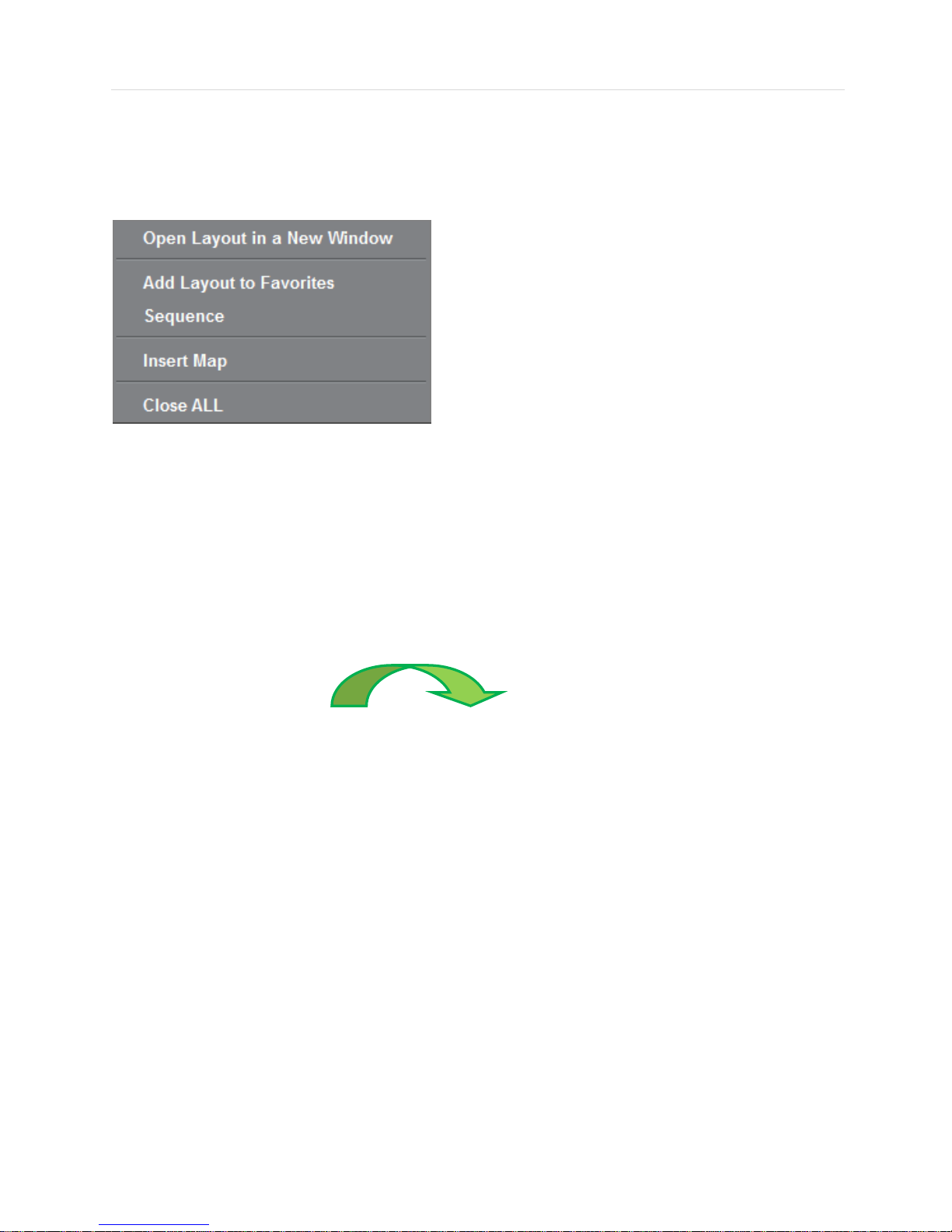
User’s Manual | 88
4.13 Favorite Registration
1) When the user want to store and utilize the current screen composition.
2) Right-click on the empty screen, then the context menu as below will be shown. You may register current screen
state for the Favorite Registration when you click the ‘Add Layout to Favorite’ button.
3) Favorite Registration can be displayed by drag and drop.
If there is an identical name for the display composition, a message window will be shown like below. If you click ‘OK’
button, current composition will be closed and the previously registered state will be activated.
Page 89

89 | Full HD Digital Video Recorder
4.14 PTZ control panel
PTZ camera control is only available in Live mode.
Before starting PTZ control, please make sure the camera you wish to control is a supported PTZ camera and is installed and
configured properly.
If Virtual PTZ is activated, able to control PTZ camera such as movement, Zoom and
Focus. PTZ can be controlled by clicking mouse on channel screen directly.
8 directional arrows allow the user to move the PTZ camera. The PTZ Camera is moved
when one of these arrows are pressed to the direction desired, and stops the movement
if mouse button is released.
Zoom In and Zoom Out.
Adjust the focus of PTZ camera.
Adjust the Iris open or close
Set PTZ presets on current view.
Adjust PTZ camera response speed. Getting Slower as moves to the right.
Activate the camera OSD menu for setup and adjust
Select the camera settings or enter the subcategories
Go to the preset location.
Page 90

User’s Manual | 90
4.15 Playback panel
CMS provides powerful and intuitive playback system. It includes seamless transition from live to archived footage,
smooth archive playback, extensive search capabilities, local files playback, etc. All playback operations can be
performed within the Playback Panel:
PTZ controller
Search the time table
Go to First.
Reverse Playback : decrease speed x 2, x4, x8, x16, x32
Step Backward.
Reverse Playback.
Pause. Or Display the play speed
Forward Playback.
Step Forward
Forward Playback : Increase speed x 2, x4, x8, x16, x32
Go to Last.
Page 91

91 | Full HD Digital Video Recorder
4.16 Search Panel
The Search panel is activated only in Search mode.
When you connect to a site in Search mode, the date is highlighted in Red color in the calendar, if the recorded data exist.
Select a specific date and time in the calendar and then recording information will be shown in the table.
(Go button) should be pressed to start playback from the selected time.
If DST is enabled, the earlier one-hour overlapped video will be shown first.
Each record mode is similar to below.
No Record White
Continuous (Yellow Color)
Panic (Red Color)
Alarm (Orange Color)
Motion (Green Color)
Click the time or move the time bar to the time you want to playback in the search panel.
For a more detailed search like below, double-click the time that you want to jump into.
Detailed search is available on a 5 minute.
Page 92
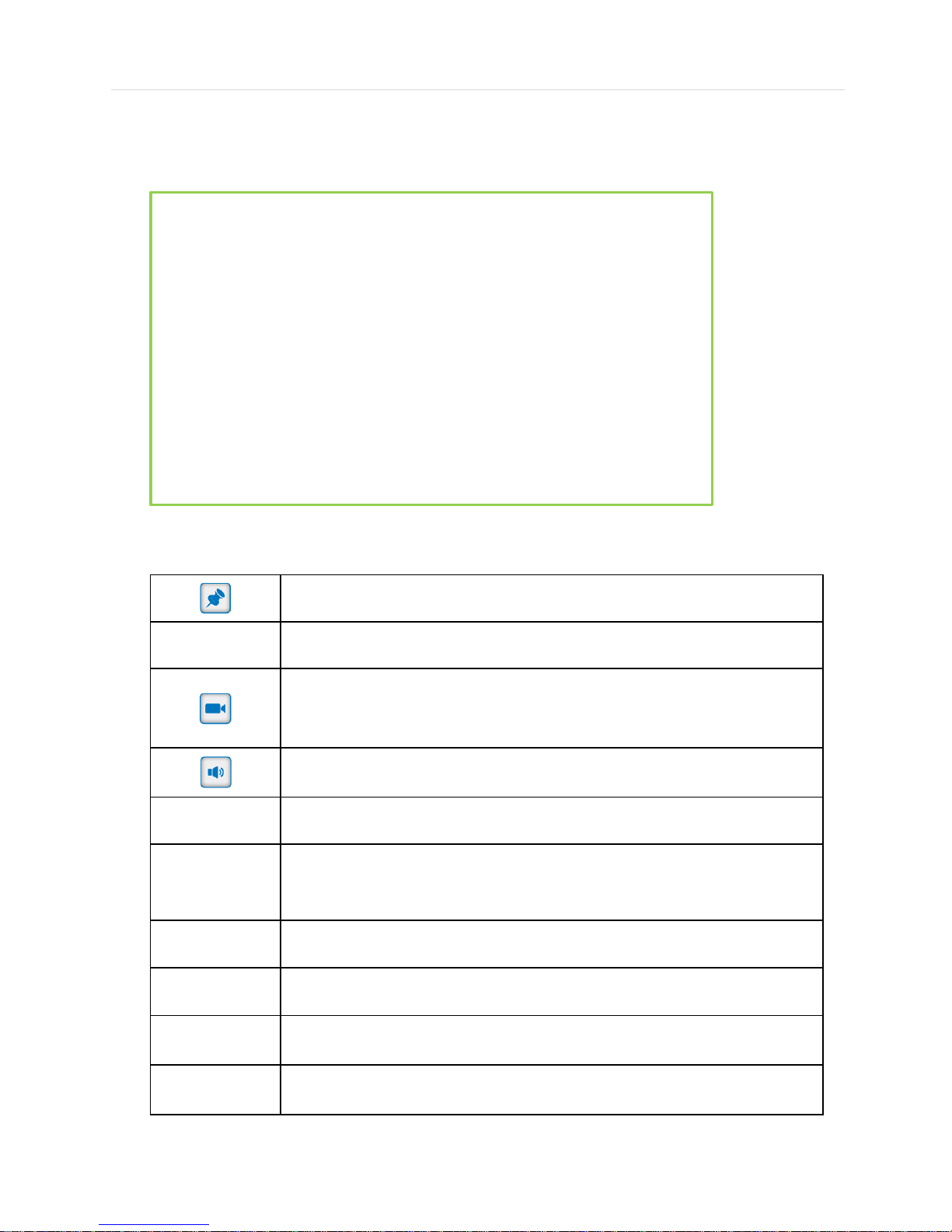
User’s Manual | 92
4.17 Display Menu
- Top of Display menu
Auto Hide and Lock the Pin Task bar(Tools) Display
Capture current Image by JPEG
Save the Export video by MP4
(Save the MP4 to the storage or other setting is “CMS settings” > “General” > “Image
Export Options”)
Audio On/Off – active : blue, disactive : gray
PTZ On/Off – active : blue, disactive : gray
When click the Digital Zoom button, the mouse cursor change the +, dragged zone will
be shown on the new tap(max.16 tab)
i. Zoom In/out use mouse scroll.
ii. Move to another section, click and move on the display
Image Adjust
OSD On/OFF
POS On/OFF
Close
Page 93
93 | Full HD Digital Video Recorder
- Bottom of Display menu
Continuous Recording
Motion event
Sensor event
Page 94

User’s Manual | 94
4.18 Add tab
If you open a new tab view, press the plus. Press the puls icon next to the veiw.
(if your mouse is on the plus icon , Add tab text box will appear.)
4.18.1 Open New View Tap
Click the plus icon , you can see the four menu.
Just click Open New View Tab.
As like above picture, new view tab will appear.
Page 95

95 | Full HD Digital Video Recorder
4.18.2 Open New View Tap
If you want see New floor plan in another tab, Click the plus icon after than click Open New Map Tab..
Import the floor plan image you want to see.
As like above picture, the floor plan image you want to see appeared in another tab.
Page 96

User’s Manual | 96
4.18.3 Open Event Report Tap
To see the event report, please click on the Open Event Report Tab.
As like above picture, you can see the Site event which was taken place in live mode
If you click the camera you want to see, you can see recent event in playback mode
Page 97

97 | Full HD Digital Video Recorder
4.18.4 Open Log Report Tap
If you want see related events log in CMS settings or related POS data (Such as Site, Text, CH, Date/Time), click the Open
Log Report Tab.
As like above picture, see the See related events log in CMS settings or
See related POS data (Such as Site, Text, CH, Date/Time) in Transaction Verification tab.
Page 98

User’s Manual | 98
4.19 Site list pop-up menu
Pop-up menu is shown, Right-click on site name
4.19.1 Site Management
Refer to 4.4 Main Toolbar (Site Management)
Page 99

99 | Full HD Digital Video Recorder
4.19.2 Event / POS Search
Search the events, System log and POS setting in CMS
Event : Search the Date/Time range, select the channel and Event Type
Page 100

User’s Manual | 100
System Log : Search the Date/Time range and select Log Type
Transaction Verification : Search the Date/Time range, POS Setup
 Loading...