

Page 1
Page 2

© Copyright 2009, NITGEN&COMPANY Co., Ltd.
All rights reserved. `
Unauthorized reproduction of part or all of this manual’s content in any form is
prohibited.
Product specifications may change without prior notice to improve functionality.
NITGEN&COMPANY the NITGEN logo are registered trademarks of
NITGEN.&COMPANY
Other names and trademarks belong to respective companies.
The font used in this product is Naver’s “Nanum”.
NITGEN&COMPANY Customer Service Center
Tel: +82.2.513.2150
Fax: +82.2.513.2191
Email: [email protected]
Page 3

3
Chapter 1 ............................................................................... 4
Before Installing .................................................................... 4
Product Package ....................................................................... 5
Chapter 2 ............................................................................... 7
Installation Environment ...................................................... 7
Installation Environment ........................................................... 8
Chapter 3 ............................................................................... 9
System Configuration ........................................................... 9
Network Mode ..........................................................................10
Standalone Mode ..................................................................... 11
Chapter 4 ............................................................................. 12
Installation ........................................................................... 12
Installation of Fixing Bracket ...................................................13
Installation of other parts .........................................................14
External Cable Connection ......................................................15
Terminal Fixing ............ 오류! 책갈피가 정의되어 있지 않습니다.
Chapter 5 ............................................................................. 22
After Installation.................................................................. 22
After Installation .......................................................................23
Page 4

4
Chapter 1
Before Installing
Product Package
Page 5
5
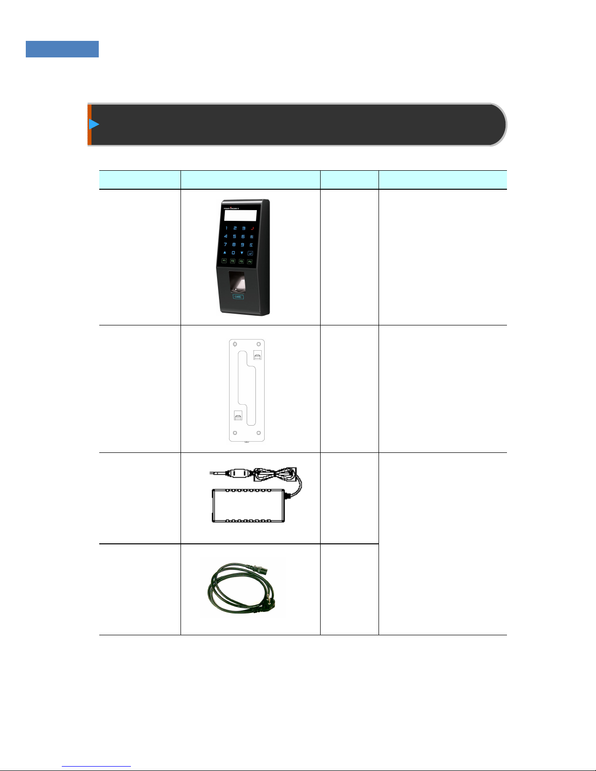
Product Package
Item Shape Quantity
Usage
Terminal
1 Access controller
Installation
Bracket
1 Fixes the terminal.
Adapter
1 Supplies power to the
terminal.
Power
Cord
1
Page 6
6
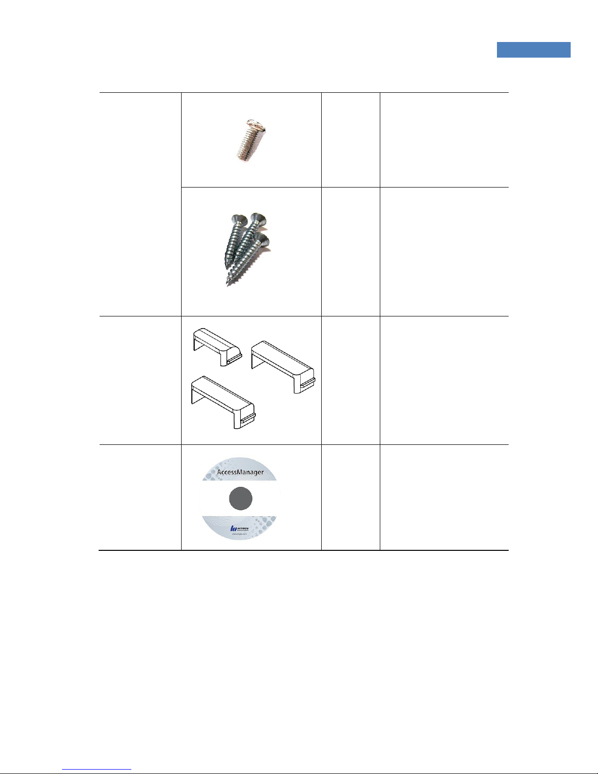
Bolts
1 Fixes the terminal.
3 Fixes the installation
bracket.
Cable Door 3 Top : 1ea
Side : 2ea
S/W CD 1 AccessManager
Professional
Software CD
Page 7

7
Chapter 2
Installation Environment
Page 8
8
Installation Environment
Select the installation location considering the following, and get
consent from the user if needed.
① This product should be installed indoors. If installed outdoors, the
product must be protected from direct sunlight, snow, and rain.
② Cables must not be exposed and it is recommended that they be
buried. If this isn’t possible due to the environment, get consent
from the user before installing.
③ Plug in the power only after all cables are connected. While the
unit is plugged in, do not disconnect the cables or connect them
to other cables.
④ The product can be used more effectively if it is installed at a
convenient height and location. The recommended height for a
normal adult is 150cm from the ground to the center of the
terminal.
⑤ Input power for the system is AC 100~240V, 50/60Hz.
Note
If the power unit is not grounded, static electricity, etc may cause
problems.
Page 9

Chapter 3
System Configuration
Network Mode
Standalone Mode
Page 10
10
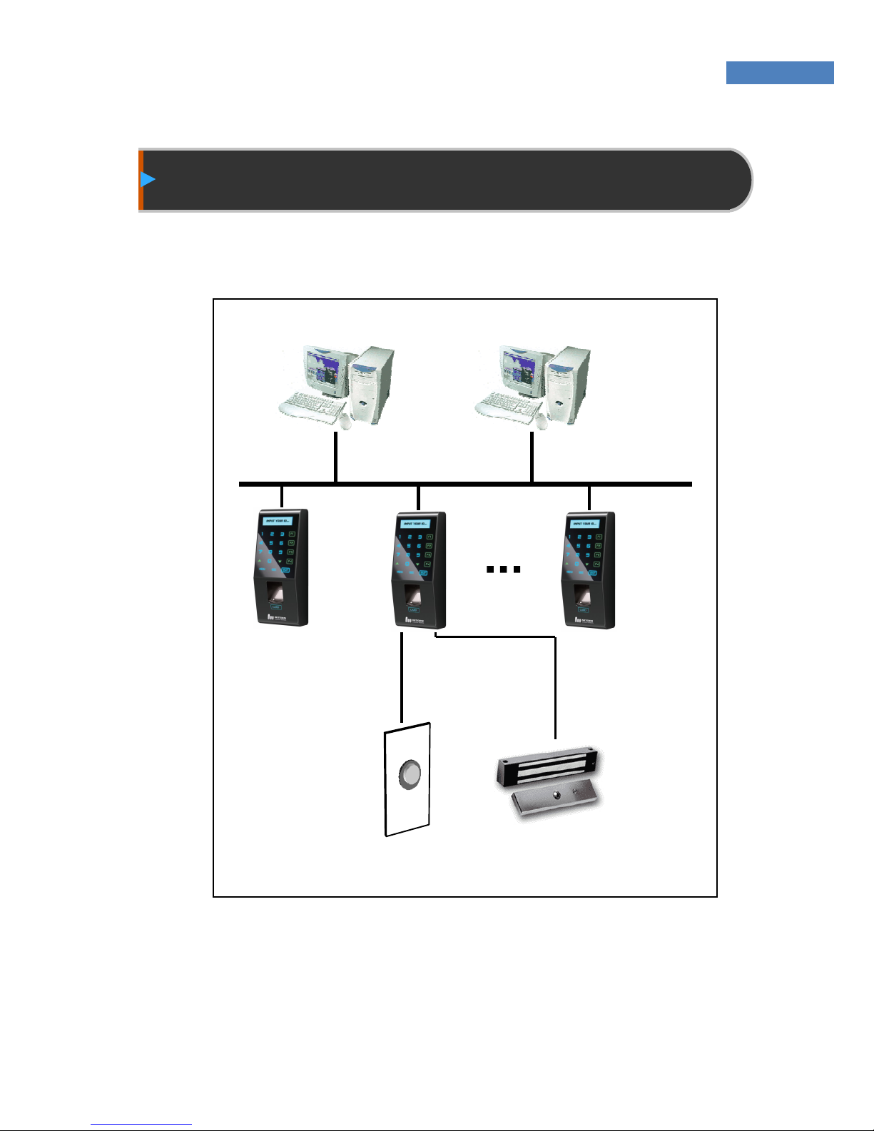
Network Mode
Terminals are connected by network. It can be remote control.
Figure3.1 Network Configuration
Network (TCP/IP)
Server PC Client PC
Terminal
Lock Door opening S/W
Page 11
11
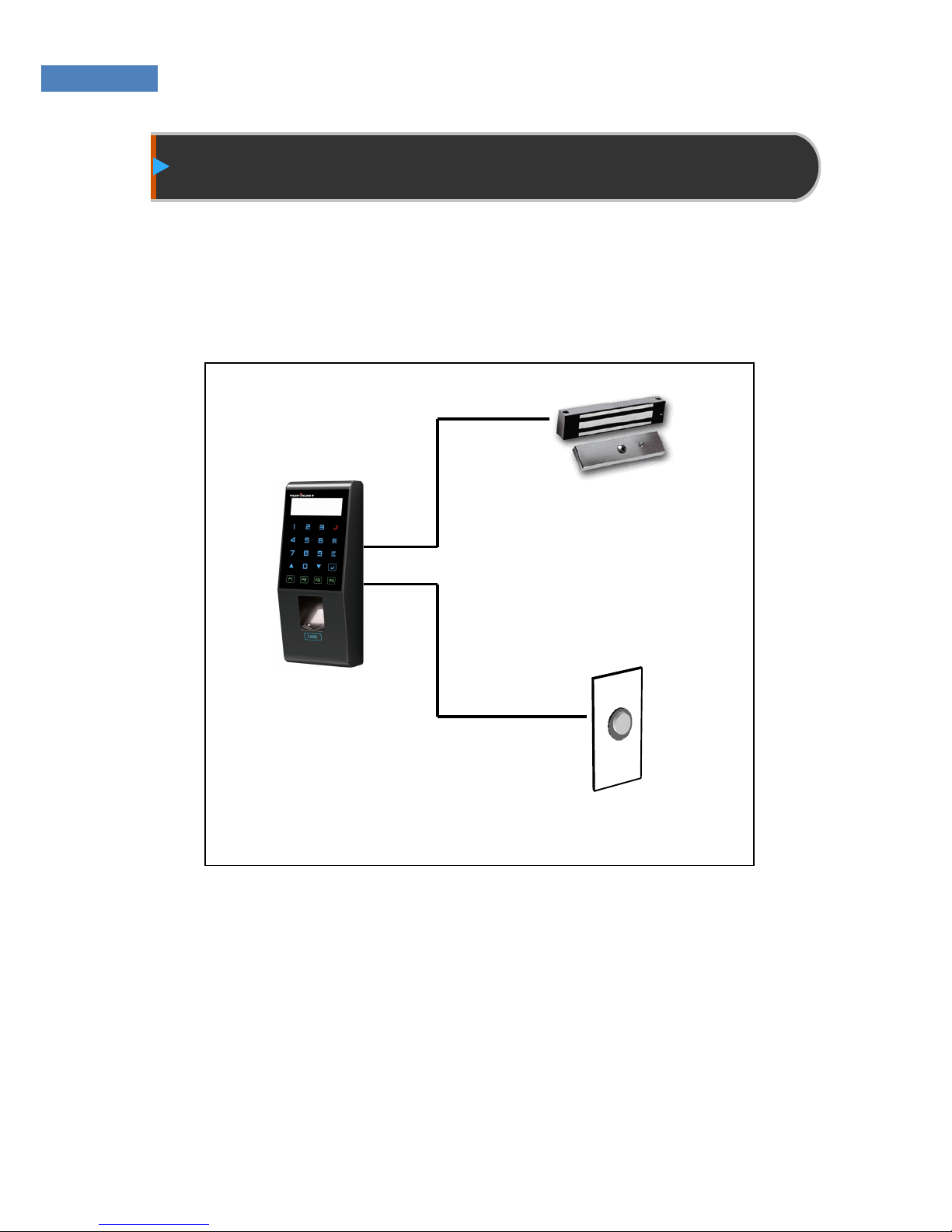
Standalone Mode
One terminals is used independently. All settings such as user
registration, deletion, and access control are performed in the
terminal alone.
Figure3.2 Terminal Configuration
Lock
Door opening S/W
Page 12

12
Chapter 4
Installation
Installation of Fixing Bracket
Terminal Connection
External Cable Connection
Terminal Fixing
Page 13
13
※ Install the product in the following order:
① Install the fixing bracket.
② Install other devices (such as lock and door switch).
③ Connect the external cable.
④ Fix the terminal.
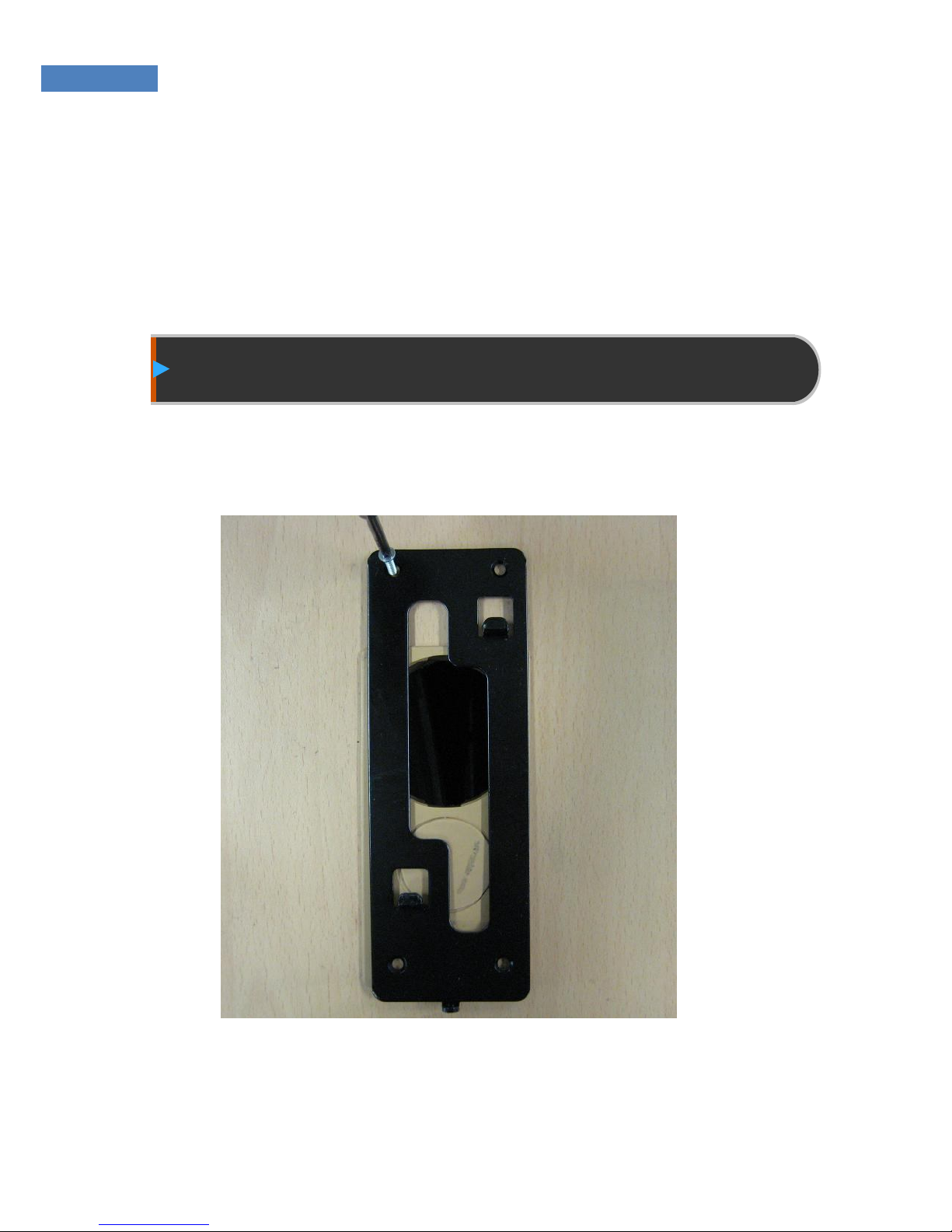
Installation of Fixing Bracket
① Select a suitable installation location, and fix the fixing bracket
with the four bolts provided with the product.
Figure4.1 Installation of Fixing Bracket
Page 14

14
Installation of other parts
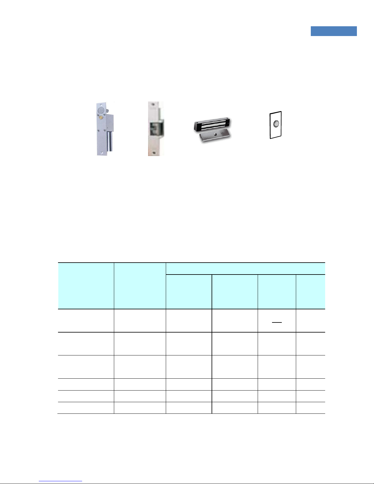
☞ The following devices can be installed, refer to the table below for
instructions.
① Locking device
② Door-opening S/W
■ Lock Types and Specifications
Type Specifications Remarks
Deadbolt Input: DC12V,
Less than 1A
Voltage output,
Fail Safe/Secure Type
Electronic Magnetic
Lock
Input: DC12V,
Less than 1A
Voltage output,
Fail Safe/Secure Type
Electric Strike Input: DC12V,
Less than 1A
Voltage output,
Fail Safe/Secure Type
Auto Door * Maximum switching
voltage: 220V DC, 250V
AC.
* Maximum switching
current: Less than 2A DC,
AC
Contact point output
☞Fail Safe Type: Unlocked, Opened upon emergency
☞Fail Secure Type: Locked, Closed upon emergency
Page 15
15
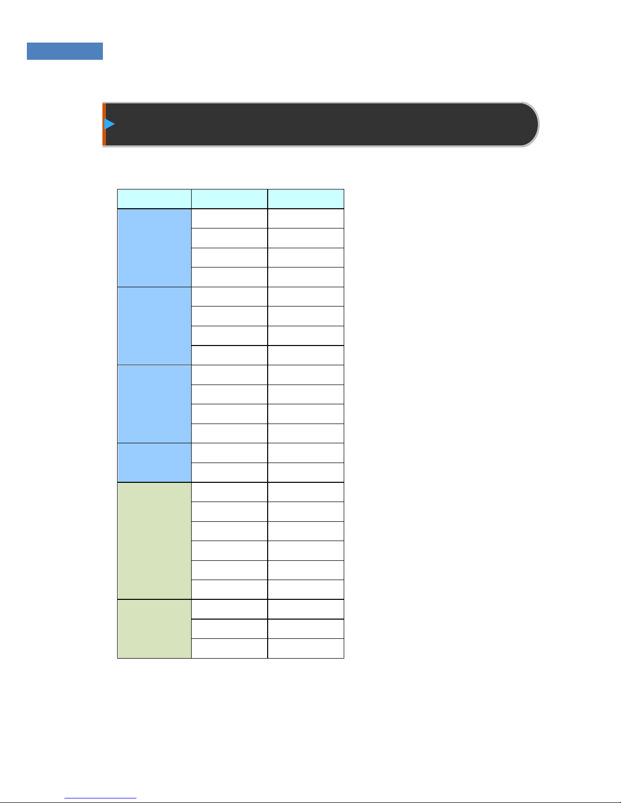
External Cable Connection
※ Install the following cables to the terminal.
Group Pin Color
485
controller
12V Red
NA Green
NA White
GND Black
Sensor
ESW Gray(Not use)
EXIT White
Door Blue
Lock Brown
Lock
NO Green
COM Yellow
NC Orange
GND Gray
Phone
Phone0 Yellow
Phone1 Orange
Wiegand
GND Black
W_IN1 Gray
W_IN0 Brown
W_OUT1 Yellow
W_OUT0 Orange
+5V Red
Aux Relay
AUX_A Brown
AUX_COM
White
AUX_B Gray
Page 16
16
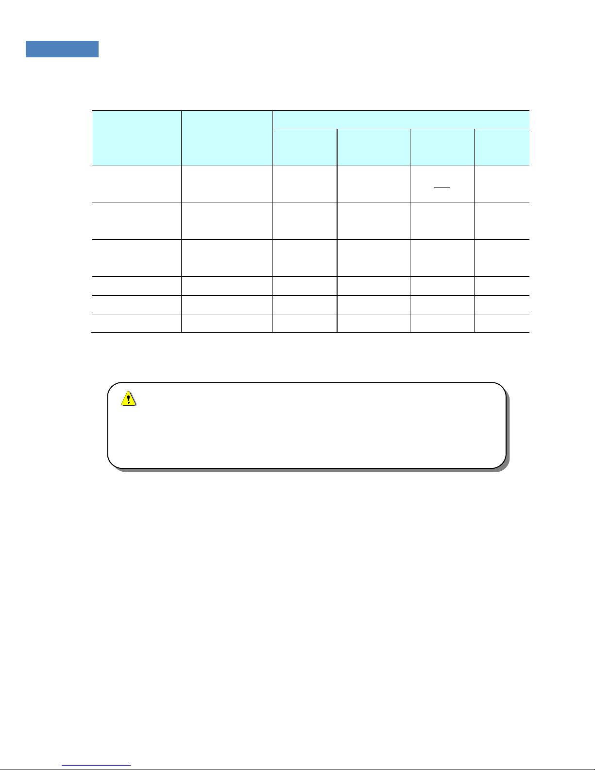
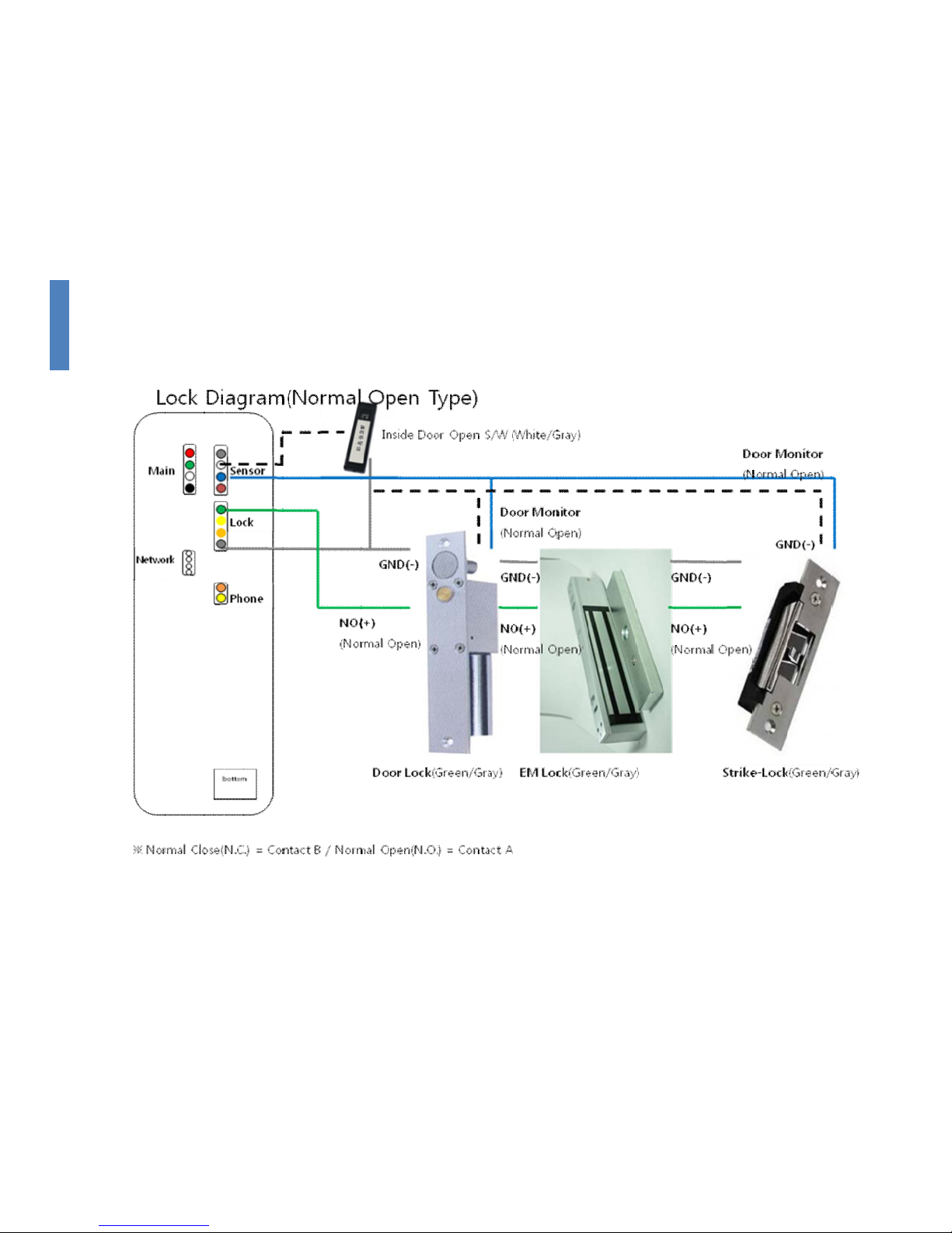
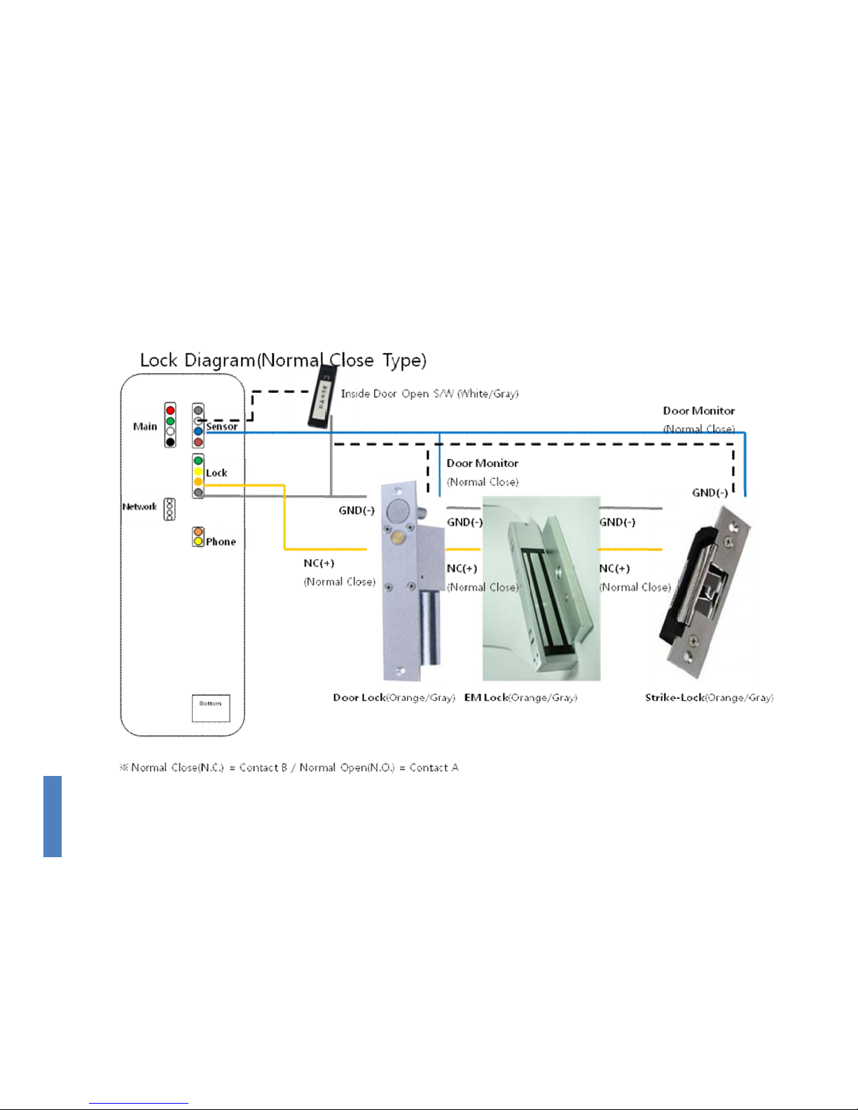
■ Power & Door Control Cable Connection
☞ Caution
① Connect the cable to the correct ports.
② If connecting the cable to an automatic door, use the contact
point output and open the [JP2] port on the main board. In the
factory setting, the [JP2] port is connected by the jumper.
③ Some locks do not have door monitoring signals.
LINE
Color
Function
Deadbolt/Strike/Electronic Magnetic Lock
Fail
Safe Type
Fail
Secure Type
Door
Monitorin
g
Door
Open
GND(Gray) GND GND GND NO
Open
Button
EXIT(White)
Door Open
Button
Open
Button
Door/Lock
(Blue/Brown)
Door
Monitoring
common
NO(Green) CONTACT_B
VCC(12V)
COM(Yellow)
COMMON
NC(Orange) CONTACT_A
VCC(12V)
※ Normal Close(N.C.) = Contact B / Normal Open(N.O.) = Contact A
Door-opening
S/W
Deadbolt Strike
Electric
Magnetic
Lock
Page 17
17
PIN
NO
Function
Automatic Door
Normal
Open
Normal
Close
Door
Monitoring
Door
Open
GND(Gray) GND NO
Open
Button
EXIT(White)
Door Open
Button
Open
Button
Door/Lock
(Blue/Brown)
Door
Monitoring
COMMON
NO(Green) CONTACT_B
Contact
COM(Yellow)
COMMON Contact Contact
NC(Orange) CONTACT_A
Contact
※ Normal Close(N.C.) = Contact B / Normal Open(N.O.) = Contact A
JP2 is jumper for supplying power(12V) to the door
lock. If you use the external power supply, those
jumper must be removed before connecting the power.
Page 18
18
Page 19
19
Page 20
20
4.3.2 Network Cable Connection
- When connecting the network cable, connect to Modular
Jack(RJ45).
Housing Cable
Cabling
PIN No. Function
RJ45, 8PIN UTP
1 TXP
2 TXN
3 RXP
6 RXN
Page 21
21
Terminal Fixing
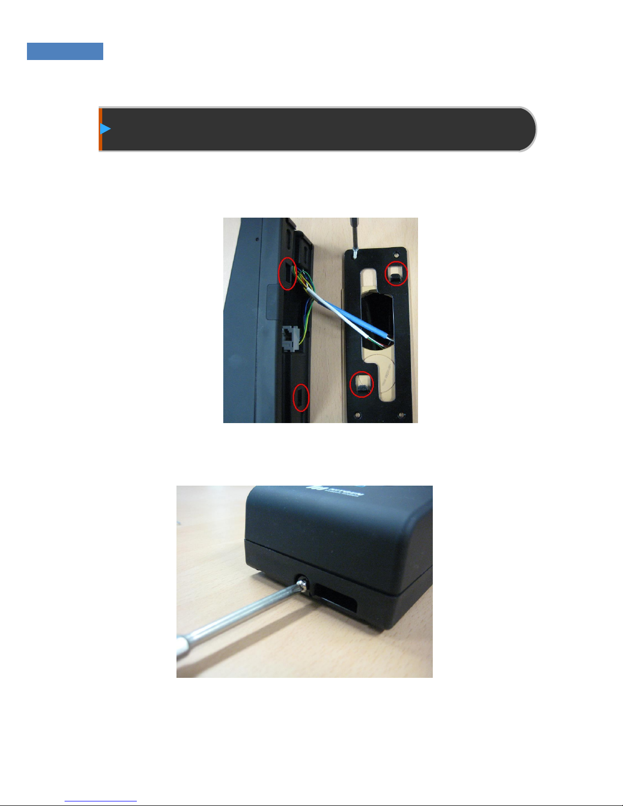
① After the cables are connected, tidy the rest of the cables at
the rear of the terminal and place the terminal on the fixing
bracket as shown in Figure 4.2.
Figure4.2 Placing the Terminal on the Fixing Bracket
② Fix the terminal using the fixing bolts as shown in Figure 4.3.
Figure4.3 Fixing the Terminal
Page 22

22
Chapter 5
After Installation
After Installation
Page 23
23
Note
Fisrt registered user has administrator right therefore, you must
initialize all user data if installer and administrator are different.
After Installation
After finishing installation, check that it was done properly and
plug in the power.
Check if the lock and other devices are properly functioning as
described below. For more information, see “FingkeyAccess
Terminal Manual” and “AccessManager Professional User
Manual.”
① When power is supplied, the initial screen with
FingkeyAccess string and Time will appear.
② Select the Network -> Normal -> “Disable” in Admin
menu of Terminal to use the standalone mode.
③ Press the Admin button and select User -> “Register” to
register user information such as ID and fingerprint.(4digit user ID is set to the default
④ Perform fingerprint authentication peripherals such as a
locking device to proceed with the Test
Page 24

24
When operating the terminal in network mode, install Access
Manager Professional and conduct the following test.
① Install the AccessManager Professional in the server PC.
Register the administrator and set initial configurations. (For
more information, see AccessManager Professional User
Manual)
② Select the Network -> Normal -> “Wireline” in Admin menu of
Terminal. (See FingkeyAccess terminal User Manual)
③ Set the network settings in the Terminal Admin menu.
④ Start the AccessManager and then register after check if the
terminal is connected.
⑤ Register a terminal user in the server PC and check that
authentication proceeds properly.
⑥ If there are no problems, delete both the server user and the
terminal user.
 Loading...