

Page 1

Total Biometric Solution
eNBio Gate
Provider
User’s Manual
V1.0
Page 2
Chapter
1. Installation
1.1 Connection
1.2 Notices
Page 3
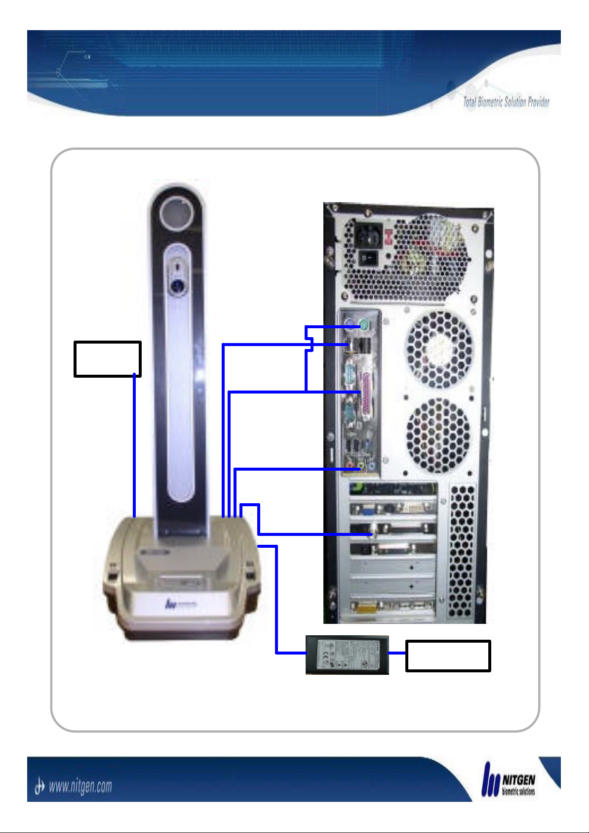
1.1 Connection
Remote
controller
USB cable
Parallel &
PS2
Audio signal
Cable
Video signal
Cable
100/240 VAC
* Connect the connectors like the upper picture.
Page 4

1.2 Notices
1. Don’t change the USB port after the
first installation into the user PC.
2. You must connect cables while the
power of PC is OFF and the eNBio
Gate power is also OFF.
3. You have to install the eNBio Gate in
the place without strong backlight. It
can make the camera movement error.
4. Don’t disassemble eNBio Gate without
NITGEN’s approval. If do, you cannot
have the A/S from us.
Page 5
Chapter
2. Usages
2.1 Enrollment
2.2 Verification
2.3 DB Seach
Page 6
2.1 Language Setting
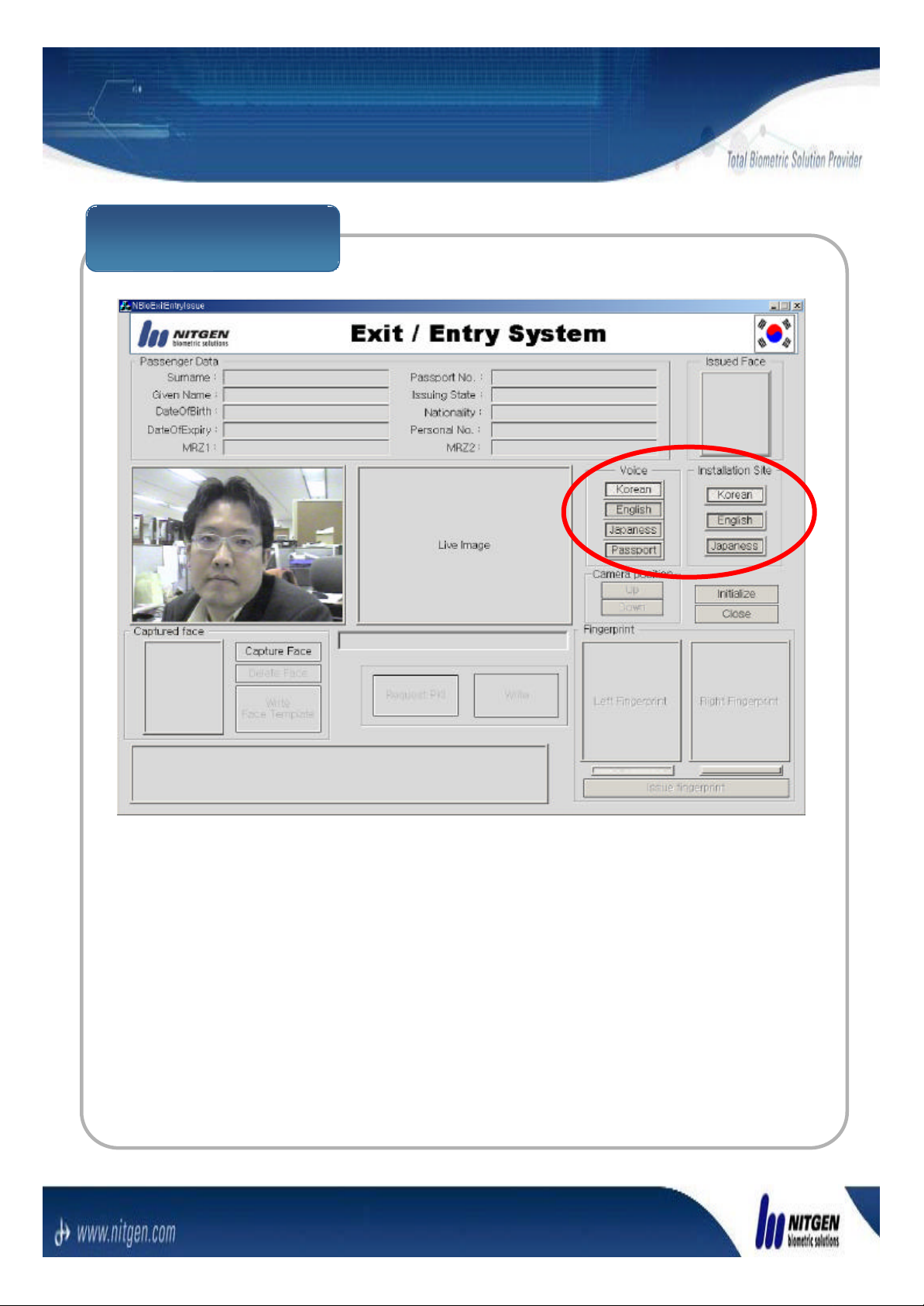
Language Setting
You can choose the user interface language with You can choose the user interface language with
buttons in the red circle in the upper Exit/Entry System buttons in the red circle in the upper Exit/Entry System
UI.UI.
Page 7
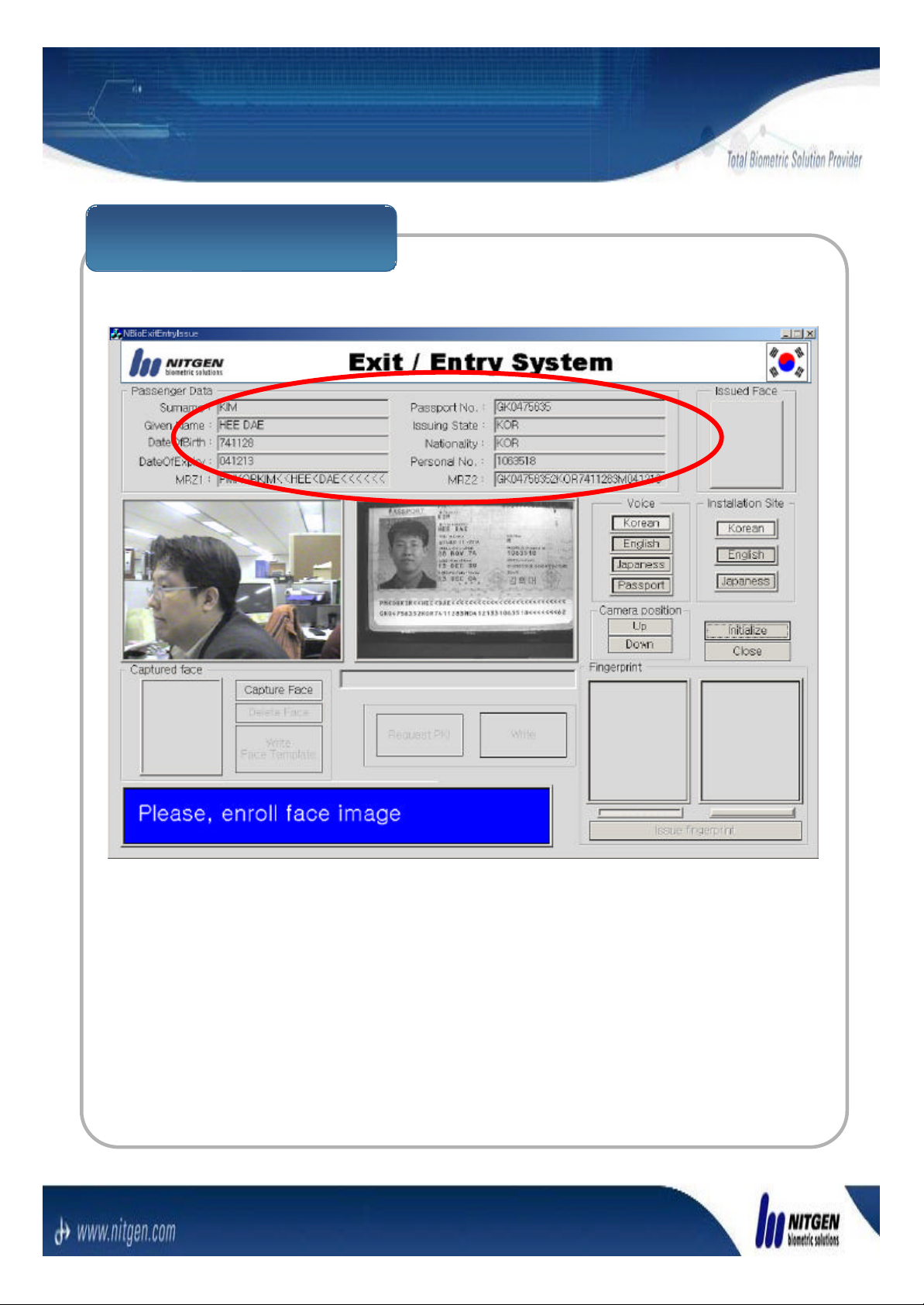
2.2 Enrollment
User data enrollment
Enter a userEnter a user’’s data in the upper Exit/Entry System User s data in the upper Exit/Entry System User
Interface. If you adopt Interface. If you adopt ‘‘Passport readerPassport reader’’, you can enter , you can enter
them automatically.them automatically.
Page 8
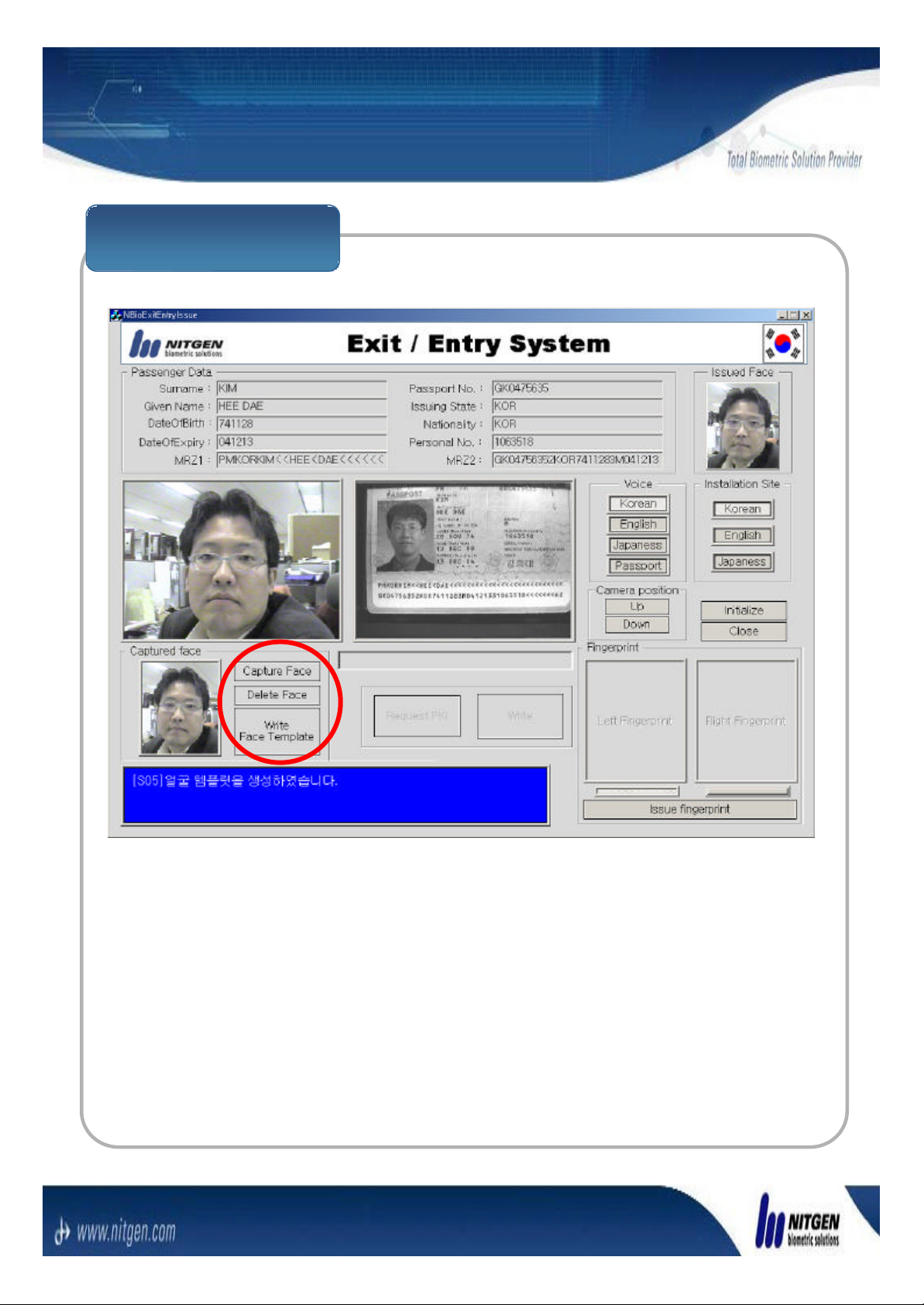
2.2 Enrollment
Face Enrollment
You can capture or delete a face image with the You can capture or delete a face image with the
‘‘Capture FaceCapture Face’’and and ‘‘Delete FaceDelete Face’’buttons in the red buttons in the red
circle of the circle of the ‘‘Exit/Entry SystemExit/Entry System’’User Interface. And User Interface. And
you can write the face template with the you can write the face template with the ‘‘Capture FaceCapture Face’’
button.button.
You can adjust camera heights automatically by You can adjust camera heights automatically by
pressing pressing
the the ‘‘AutoAuto’’button on the remote controller and manually button on the remote controller and manually
with the with the ‘‘UpUp’’and and ‘‘DownDown’’buttons.buttons.
Page 9
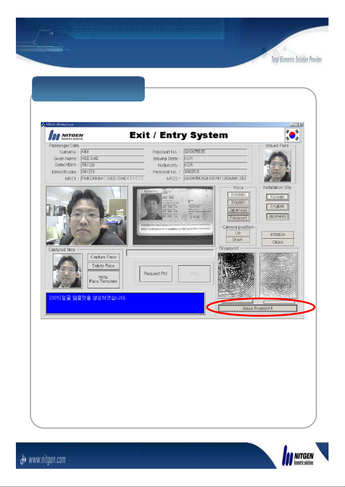
2.2 Enrollment
Fingerprint Enrollment
Enroll the fingerprint template by using the Enroll the fingerprint template by using the ‘‘Issue Issue
fingerprintfingerprint’’circled by red line in the upper UI.circled by red line in the upper UI.
Page 10
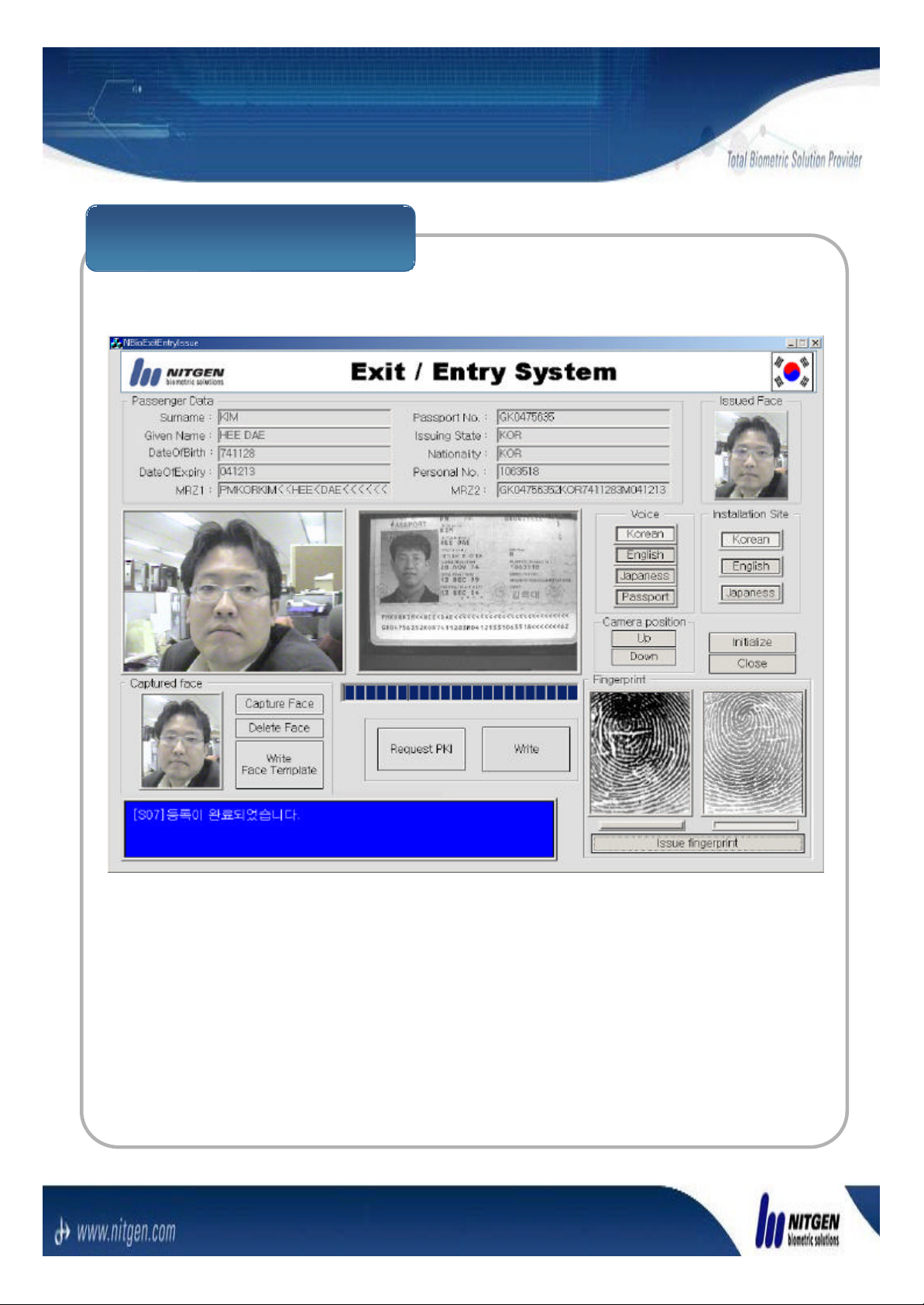
2.2 Enrollment
Enrollment Verification
The upper picture is the state of the end of enrollment.The upper picture is the state of the end of enrollment.
Page 11
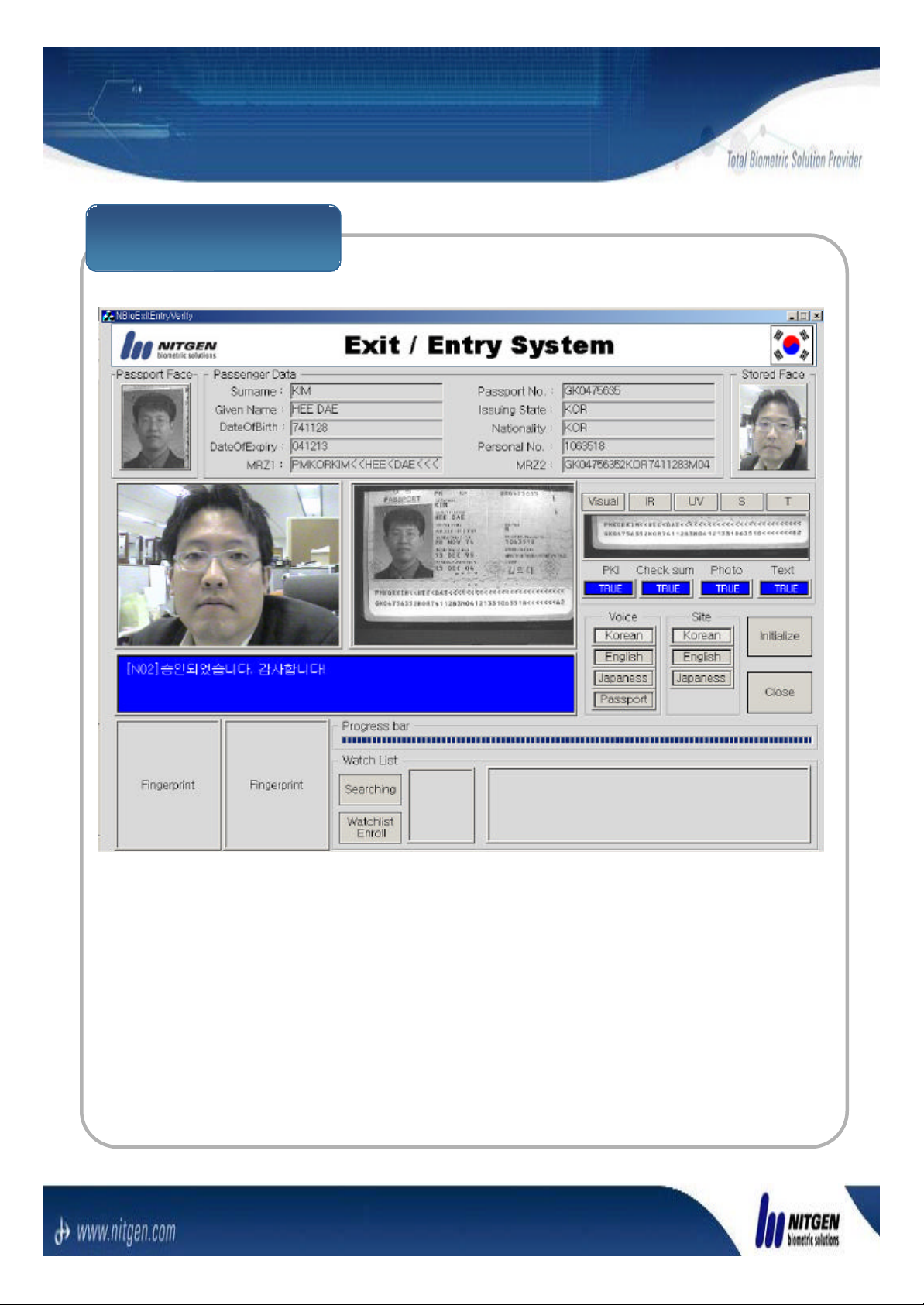
2.3 Verification
Face Verification
If you enter User Data or scan passport in the reader in If you enter User Data or scan passport in the reader in
verification mode, face and fingerprint verification is verification mode, face and fingerprint verification is
executed automatically in the turn.executed automatically in the turn.
Page 12
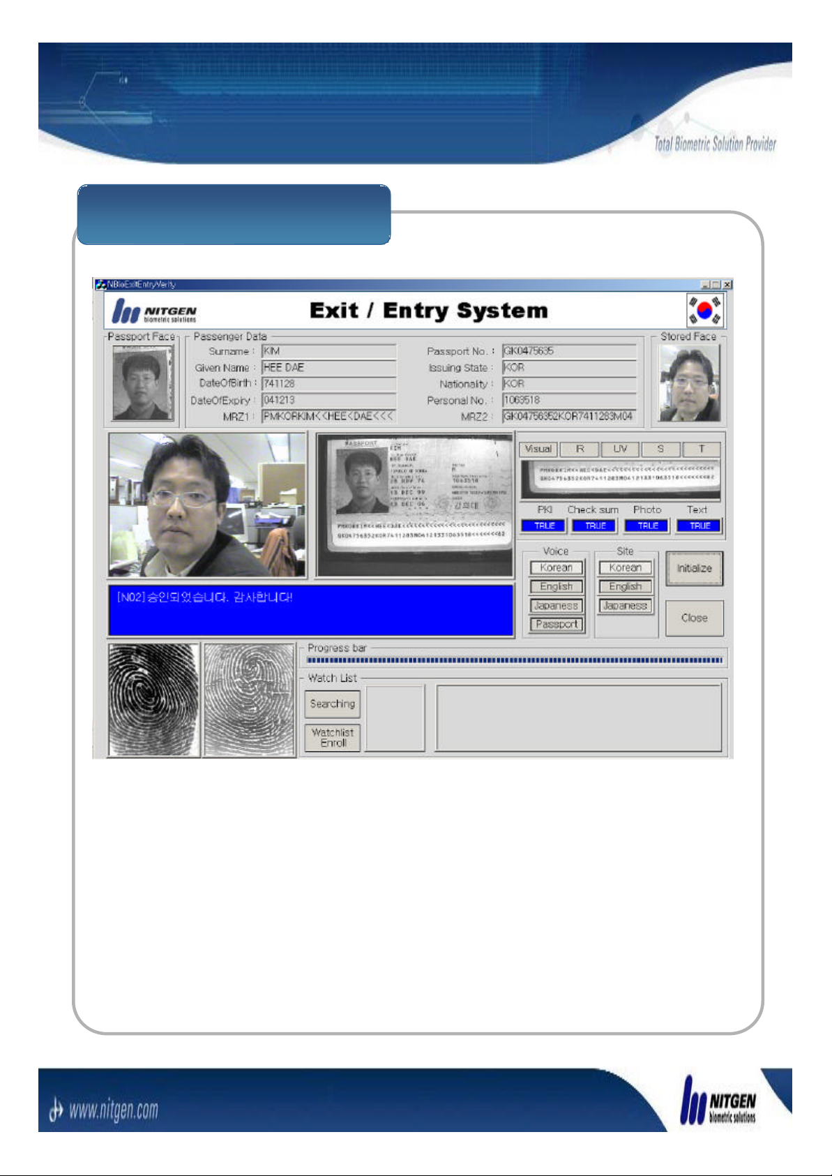
2.3 Verification
Fingerprint Verification
If the message If the message ““Place your fingerPlace your finger”” is happen, place is happen, place
user fingers to the fingerprint sensors in the turn.user fingers to the fingerprint sensors in the turn.
Page 13
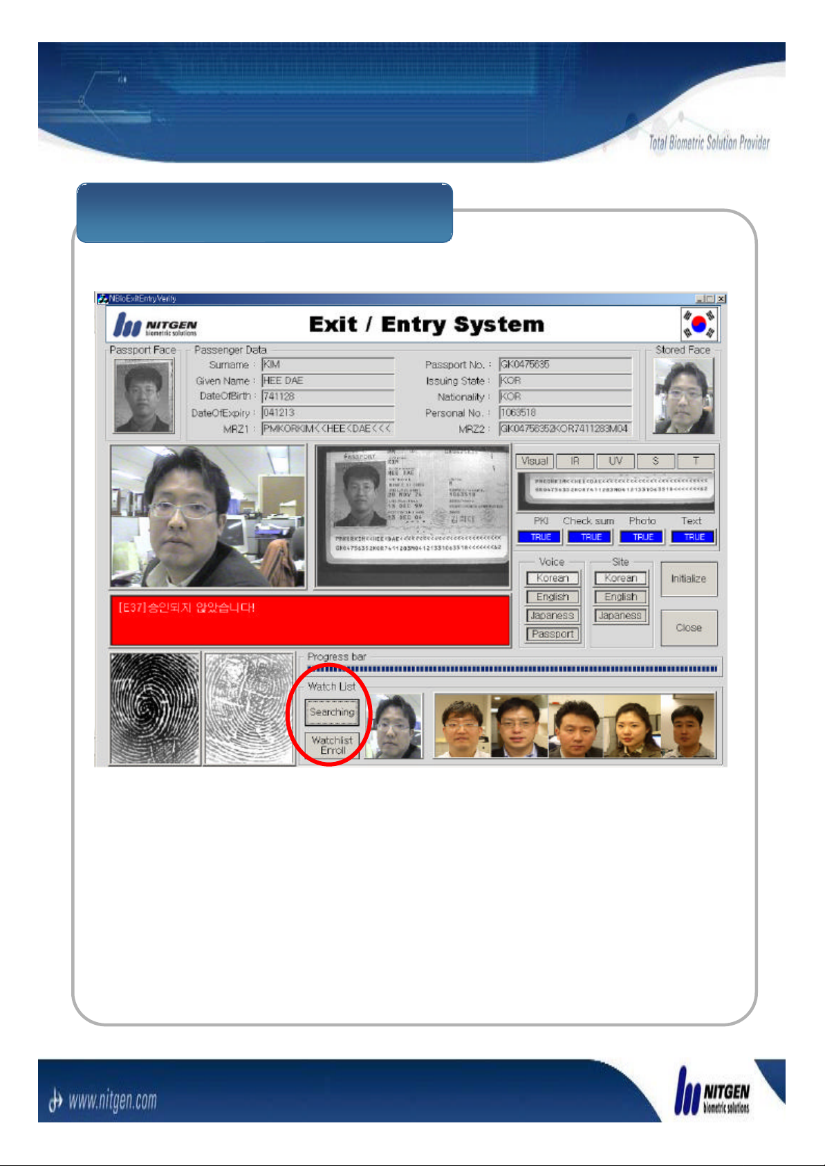
2.3 Verification
Black List Search for Fail
If the Verification result is fail, the message If the Verification result is fail, the message ‘‘The The
verification is failverification is fail’’is displayed. You can search the is displayed. You can search the
candidates by using searching Button in the upper UI.candidates by using searching Button in the upper UI.
Page 14
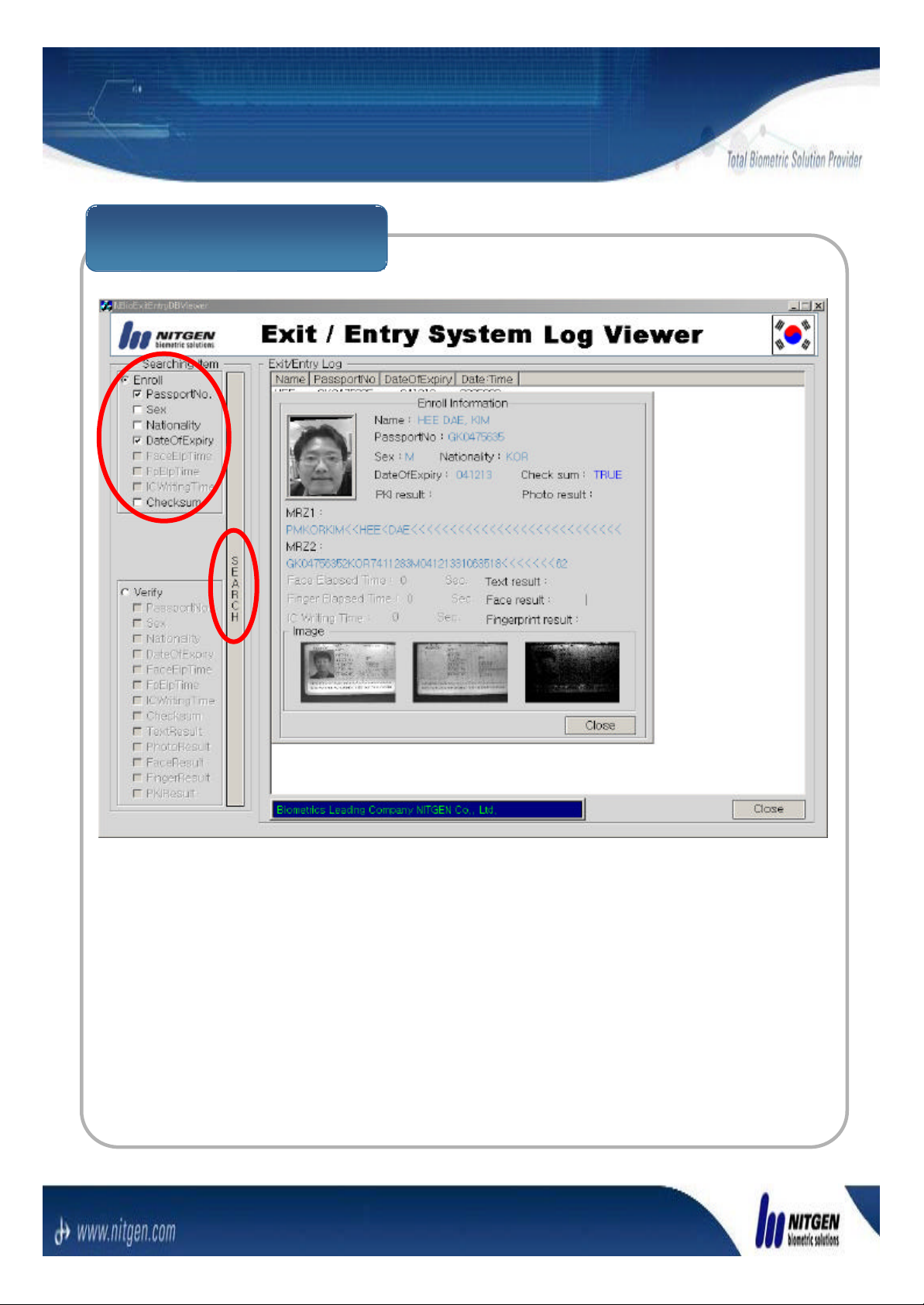
2.4 Log DB
Enrollment Log Search
You can search Enrollment Log data for the various You can search Enrollment Log data for the various
cases with the option check boxes in the upper picture.cases with the option check boxes in the upper picture.
Page 15
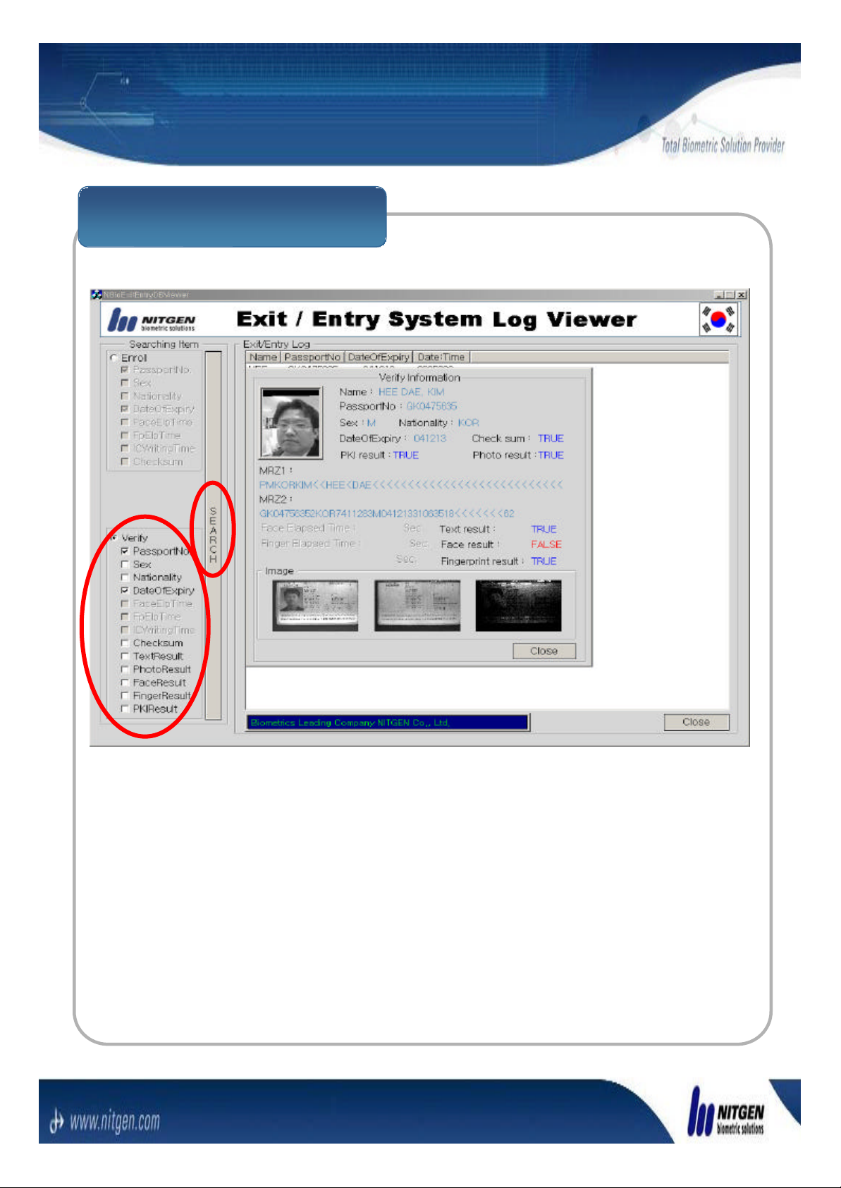
2.4 Log DB
Verification Log Search
You can search Verification Log data for the various You can search Verification Log data for the various
cases with the option check boxes in the upper picture.cases with the option check boxes in the upper picture.
Page 16

FCC NOTICE
THIS DEVICE COMPLIES WITH PART 15 OF THE FCC RULES.
OPERAT ION IS SUBJECT TO THE FOLLOWING TWO CONDITION:
(1) THIS DEVICE MAY NOT CAUSE HARMFUL INTERFERENCE, AND
(2) THIS DEVICE MUST ACCEPT ANY INTERFERENCE RECEIVED,
INCLUDING INTERFERENCE THAT MAY CAUSE UNDERSIRED
OPERATION.
This equipment has been tested and found to comply with the limits for a Class B
digital device, pursuant to part 15 of the FCC Rules. These limits are designed to
provide reasonable protection against harmful interference in a residential installation.
This equipment generates, uses and can radiate radio frequency energy and, if not
installed and used in accordance with the instructions, may cause harmful interference
to radio communication. However, there is no guarantee that interference will not
occur in a particular installation. If this equipment does cause harmful interference to
radio or television reception, which can be determined by turning the equipment off and
on, the user is encouraged to try to correct the interference by one or more of the
following measures :
- Reorient or relocate the receiving antenna.
- Increase the separation between the equipment and receiver.
- Connect the equipment into an outlet on a circuit difference from that to which
the receiver is connected.
- Consult the dealer of an experienced radio/TV technician for help.
NOTE : The manufacturer is not responsible for any radio or TV interference caused by
unauthorized modifications to this equipment. Such modifications could void the user’s
authority to operate the equipment.
 Loading...