

Page 1
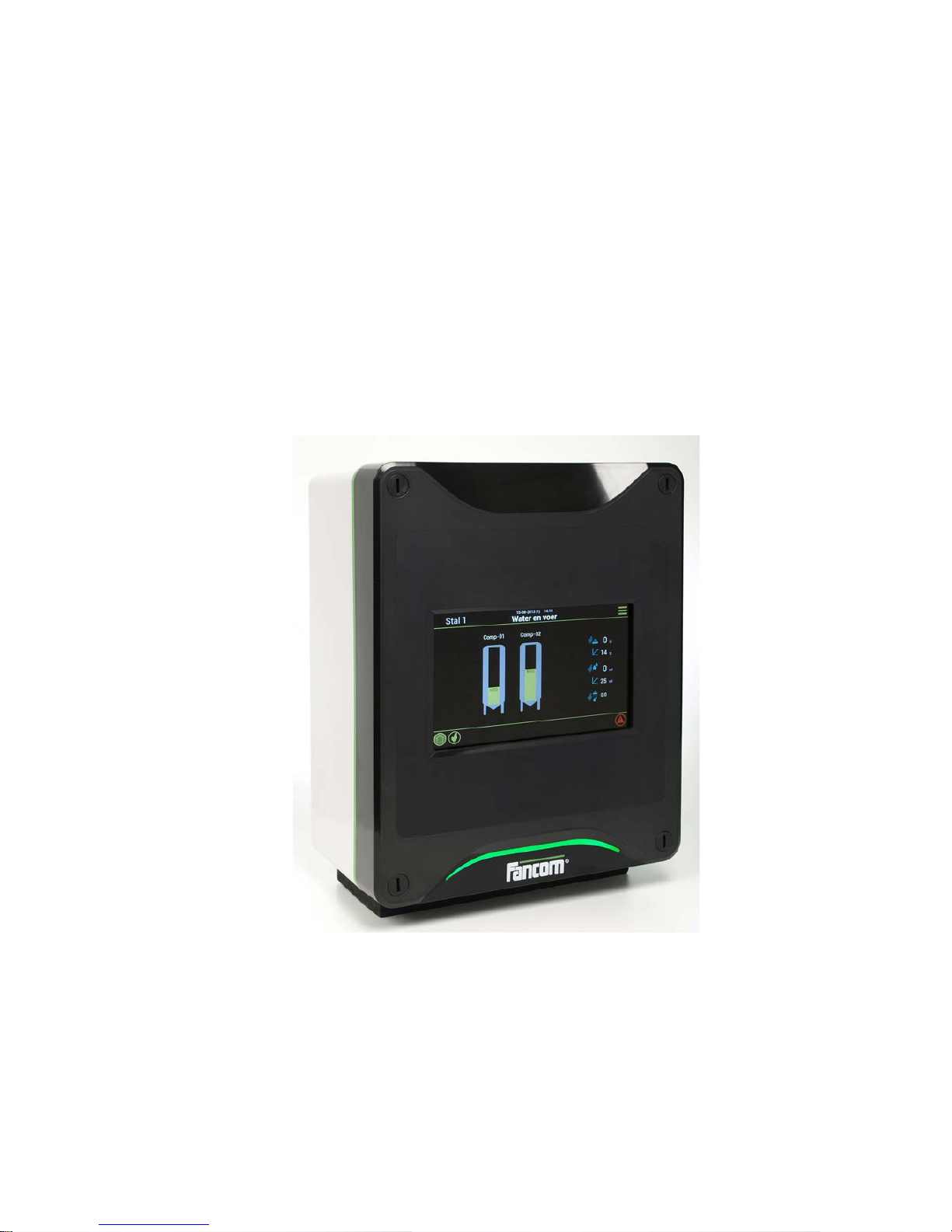
LUMINA 40
LUMINA 40
LUMINA 40 TOUCH
F40
INSTALLATION MANUAL
VERSION C1
g
Page 2

N.B.: The original, authentic version of this manual is the English version produced by Fancom B.V. or one of its
daughter companies (referred to further as Fancom). Any modifications introduced to this manual by third parties
have neither been checked nor approved by F ancom. M odifications are t aken by Fanc om to inclu de translation s into
languages other than English and the insertion and/or deletion of text and/or illustrations to/from the original
contents. Fancom cannot be held liable for any damages, injury, guarantee claims and other claims relating to this
type of modification, in as far as these modifications result in a content that differs from the original English version
of this manual produced by Fancom. For the latest information about product installation and operation, please
contact the customer servic e dept. and/or the techni cal servi ce dept. of the F ancom com pany concerned. I n spite of
the care taken when c ompil ing this m anual, if y ou s hould disc over any err ors, p lease infor m Fanc om B.V. in w riting.
Fancom B.V., PO Box 7131, 5980 AC Panningen (the Netherlands).
Copyright © 2013 Fancom B.V.
Panningen (the Netherlands)
All rights reserved. N othi ng f rom t his manual may be c opied, distribut ed or tran slated into ot her lang uages, par tly or
wholly, without express prior written permission from Fancom. Fancom reserves the right to modify this manual
without notice. Fancom c an giv e no guar antee, neither im plicit nor ex plicit, for thi s manu al. Al l ris ks are f or th e user.
This manual has been compiled with the utmost care. If, however, you should discover an error, please inform
Fancom B.V.
Art.Nr. 5911645
GB130715
Page 3

Lumina 40 Table of contents
i
Table of contents
1. General introduction .................................................................................................................................. 1
1.1 Documentation with the control computer ....................................................................................... 1
1.2 How to use this manual .................................................................................................................. 1
1.3 Fancom helpdesk ........................................................................................................................... 2
1.4 F-Central FarmManager™ .............................................................................................................. 2
2. The feed installation ................................................................................................................................... 3
2.1 Important terms .............................................................................................................................. 3
3. Installing the control computer ................................................................................................................. 5
3.1 Install ation menu ............................................................................................................................ 5
3.2 Overview installation process ......................................................................................................... 5
3.3 Connections and addresses ........................................................................................................... 5
4. System ......................................................................................................................................................... 6
4.1 System ............................................................................................................................................ 6
4.2 SD Card Menu ................................................................................................................................ 7
4.3 Application ...................................................................................................................................... 8
4.4 Communication ............................................................................................................................... 8
4.5 IO-Test ............................................................................................................................................ 9
5. House setup .............................................................................................................................................. 10
5.1 Tab page Number ......................................................................................................................... 10
5.2 Tab page Dose in/out ................................................................................................................... 10
5.3 Tab page Clocks ........................................................................................................................... 11
6. Silos and ingredients ............................................................................................................................... 13
6.1 Tab page Silo ............................................................................................................................... 13
6.2 Tab page Alarm ............................................................................................................................ 14
6.3 Tab page Bulk .............................................................................................................................. 14
6.4 Tab page Dual .............................................................................................................................. 15
6.5 Ingredients .................................................................................................................................... 15
7. Weigher ..................................................................................................................................................... 16
7.1 Weigher ........................................................................................................................................ 16
7.2 External registration ...................................................................................................................... 20
8. Feed place ................................................................................................................................................. 21
9. Clocks, external registration and alarms ................................................................................................ 22
9.1 Feed clock .................................................................................................................................... 22
9.2 Water clock ................................................................................................................................... 22
9.3 Light clocks ................................................................................................................................... 23
9.4 Extra clock .................................................................................................................................... 24
9.5 Registration .................................................................................................................................. 25
9.6 External alarms ............................................................................................................................. 26
10. Checks and tests ...................................................................................................................................... 28
10.1 Weigher test ................................................................................................................................. 28
11. Technical specifications .......................................................................................................................... 29
11.1 Interior control computer ............................................................................................................... 30
11.2 FDP25 .......................................................................................................................................... 30
11.3 IOB.4 ............................................................................................................................................ 31
11.4 FRM.8 ........................................................................................................................................... 31
11.5 Connection FNet and I/O-net ........................................................................................................ 32
12. Appendix: Concept feeding system ........................................................................................................ 33
12.1 Bulk feed and dosing at the same time (feeding NOT BLOCKED during filling silo) ..................... 34
Page 4

Lumina 40 Table of contents
ii
12.2 Bulk feed after stopping the feeding process (feeding BLOCKED during filling silo) .................... 34
13. Appendix: EG-declaration of compliance ............................................................................................... 36
Page 5
Lumina 40 General introduction
1
1. General introduction
This manual has been compiled with the utmost care. If, however, you should discover an error, please inform
Fancom B.V..
1.1 Documentation with the control computer
The documentation consists of the following man ual s:
• User's manual
The user's manual is intended for th e end user . This m anual s upplies infor mation about wor king with the contr ol
computer after installation.
• Installer's manual
The installer's manual is intended for installers. This manual supplies information about connecting and
configuring the control computer.
• Operation and safety instructions
These subjects are covered in a separate manual. This manual also applies to other control computers in the
Fancom F2000-line. Always read the safety instructions and warnings carefully before using the control
computer.
Always keep this manual close to the control computer.
1.2 How to use this manual
The following symbols are used in this manual:
Tips and suggestions.
Note providing recommendations and additional information.
Warning indicating damage to the product if you do not follow procedures carefully.
Warning indicating danger to humans or animals.
Electrical shock hazard. Danger to humans and animals.
Example of a practical application of the described functionality.
Calculation example.
Describes the key combinations for arriving at a particular screen.
Decimals
The control computer an d this manual use a d eci ma l p oin t i n values. For example : a weight is shown a s 1.5 k g ( n ot
as 1,5 kg).
Page 6

Lumina 40 General introduction
2
1.3 Fancom helpdesk
For any questions and support, please contact the local Fancom Sales & Service Center.
1.4 F-Central FarmManager™
Virtually all Fancom equipmen t can be c ontr o lle d and m ana g ed fr om a cent ra l lo cati on. This requires the F-Central
FarmManager software package and a comm unication modul e. The screens in the co ntrol compu ters are al so used
in F-Central FarmManager. This mean s you can start w orkin g immed iate ly .
Page 7

Lumina 40 The feed installation
3
2. The feed installation
The Lumina 40 is a computer used to control a feed installation.
With the Lumina 40 the feed is transported fro m a weighed si lo to the house.
Parts of the feed installation
A typical feed installation controlled by the Lumina 40 consists of the following parts:
• 1(single) or 2(duo) silos. The 2(duo) silos version is placed on one frame.
• Dosing out auger(s) of feed to the hoppers.
• Feed lines with augers to transport the feed from the hoppers to the feed pans.
• Sensors, controllers and auger drive mech ani sm.
2.1 Important terms
2.1.1 Afterflow
The afterflow is the amount of feed that still flows after the auger has been stopped.
With automatic dosing in base d on weight the c ontrol comput er takes an after flow into acco unt. The dosing in a uger
will stop before the weigher registers the required weight.
The afterflow does not need to be set: the control computer calculates this automatically and adjusts this value
during the feed process. The afterflow will not be adjusted if the actual afterflow is higher than the max. dosing in
difference of the ingredient.
2.1.2 Capacity
The dosing capacity of the silo must be set in the control computer. This setting is used in the following situations:
• Determination of the maximum dosing time if the minimum amount decrease in 30 sec has not been set. The
maximum dosing time is five times the necessary calculated time. If Capacity Kg/minute has not been set
either, the control computer will use a maximum dosing time of 60 minutes.
• Dosing in feed ingredient s based on T IME. I f the amount to be dosed is less than t he afterfl ow , dosing in is t ime
based.
2.1.3 Min. decrease
The control computer will give a signal if the feed amount in the weigher does not decrease sufficiently within 30
seconds. If not enough is dosed in of a feed ingredient, the control computer will try to re-start the entire dosing
process several times.
If an ingredient cannot be fully dosed from a silo, the control computer will try to switch to another silo storing the
same ingredient. If this is not possible, the control computer can use a replacement ingredient. The control
computer will give a message. If finding a replacement ingredient also fails, the control computer will stop the feed
process and give a loud alarm.
2.1.4 Max. bulk time
If the bulk button is activated, the feed r egistrat ion will be registere d based on auger cap acity and not on s ilo weight.
As long as the input is HIGH, the time will repeatedly be initiated according to the set time. At the moment that the
input is LOW, the remaining time will be repeatedly decreased to 0. Registration will then be based on silo weight
again.
Page 8

Lumina 40 The feed installation
4
2.1.5 Max. permitted dos.dif (%)
The control computer compares the actual amount with the required dosing in amount. If the maximum dosing in
difference is ex ceeded, t he co ntr ol c omp uter will stop the fee d process, then give a lo ud ala r m. If t oo little has bee n
dosed in, the dosing in process of the required ingredient will be re-started.
If the permitted difference is less than the amount that can be dosed in in one second, the control computer will
make the permitted difference equal to the amount that can be dosed in in one second.
Page 9
Lumina 40 Installing the control computer
5
3. Installing the control computer
3.1 Installation menu
The installer can configure the control computer using the installation menu. This menu also contains screens for
standard system settings and diagnos es.
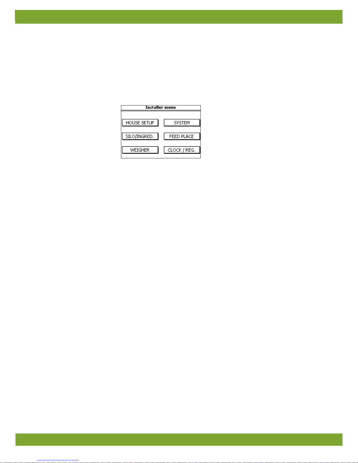
To call up the installation men u: pre ss t he n av igat ion keys UP and DO WN simultaneously for a few se con ds. T he
following installation menu will appear :
3.2 Overview installation process
Follow the steps below to install the control computer:
1. System settings
Settings not linked to the feed process, such as date, time and communication with FarmManager.
2. House set up
General settings such as the number of silos and alarms clocks used.
3. Silos and ingredients
Settings of the silo(s), feed ingredients and dosing in augers used.
4. Weigher
Settings of the weigher used.
5. Feed place
Settings of the hoppers and feed lines used.
6. Clocks, registration and external alar ms
Settings of the clocks, input for external registration and external alarms.
3.3 Connections and addresses
The control computer has various inputs and outp uts to conn ect ex ternal equ ipm ent.
The inputs and outputs consist of digital inputs (DI), digital outputs (DO), analog inputs (AI) and analog outputs
(AO).
Addresses
The address of the chosen connection must be entered at various places in the system settings.
An input or output address consists of two parts, separated by a decimal point: NN.MM
The first part (NN) is the hardware address:
• For connection to the internal hardware (on the central processing unit): NN = 0
• For connection to an external help card (IO-net number): NN = 1 to 31
The second part (MM) is the sequence number of the specific connection: MM = 1 to 99.
Page 10
Lumina 40 System
6
4. System
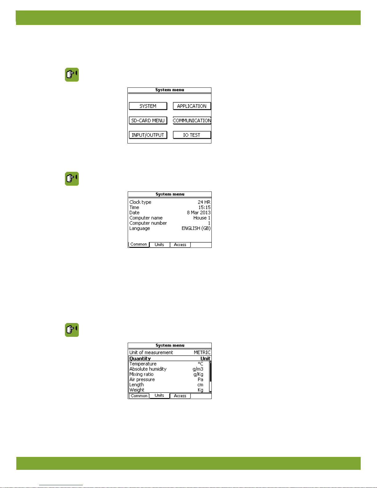
Access the system menu by pressing the UP and DOWN navigation key s simul taneously for a few seconds.
SYSTEM
4.1 System
SYSTEM SYSTEM tab page Common
Clock type
Setting of the 12 or 24 hour time indication.
Time and Date
Setting of the current time and date
Computer name
Setting of the name of the control computer.
Computer number
Setting of the sequence number of the control computer in the network.
Language
Setting of the program language.
SYSTEM SYSTEM tab page Units
Unit of measurement Setting to simultaneously set all units to METRIC or NON-METRIC.
Page 11
Lumina 40 System
7
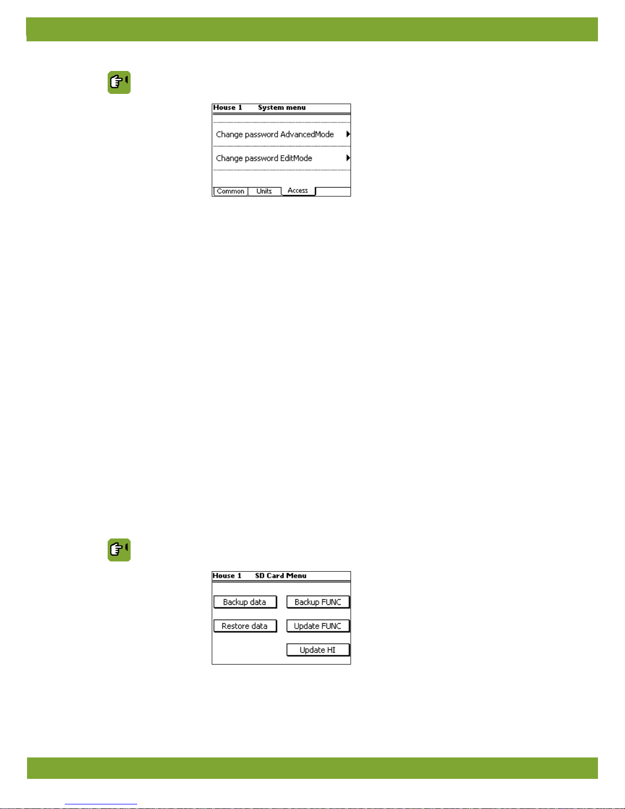
SYSTEM SYSTEM tab page Access
Change password
AdvancedMode
Setting of a password to protect advanced user settings (option More) from use by
non-authorised users.
• The password must contain four numbers.
• Enter code 1111 to deactivate the passw or d prote ctio n.
• When the correct password has been entered, all user screens can be accessed.
• The system will request the password again, if the controller is not used for a few
minutes.
Change password
EditMode.
Setting of a password so that only authorised users can change the user settings.
• The password must contain four numbers.
• Enter code 1111 to deactivate the passw or d prote ctio n.
• If you have entered a password different to 1111, the control computer will request
the password when you try to change a setting. After you have entered the correct
password, the setting can be changed.
• The system will request the password again, if the controller is not used for a few
minutes.
4.2 SD Card Menu
The set data and the operati ng progr am in th e control comput er can be t ransferr ed to a n SD-card. This data can be
copied back onto the control computer from the SD-card. This must only be performed by an authorised installer,
except when backups are made.
Place the SD-card in the SD holder on the FUNC (CPU).
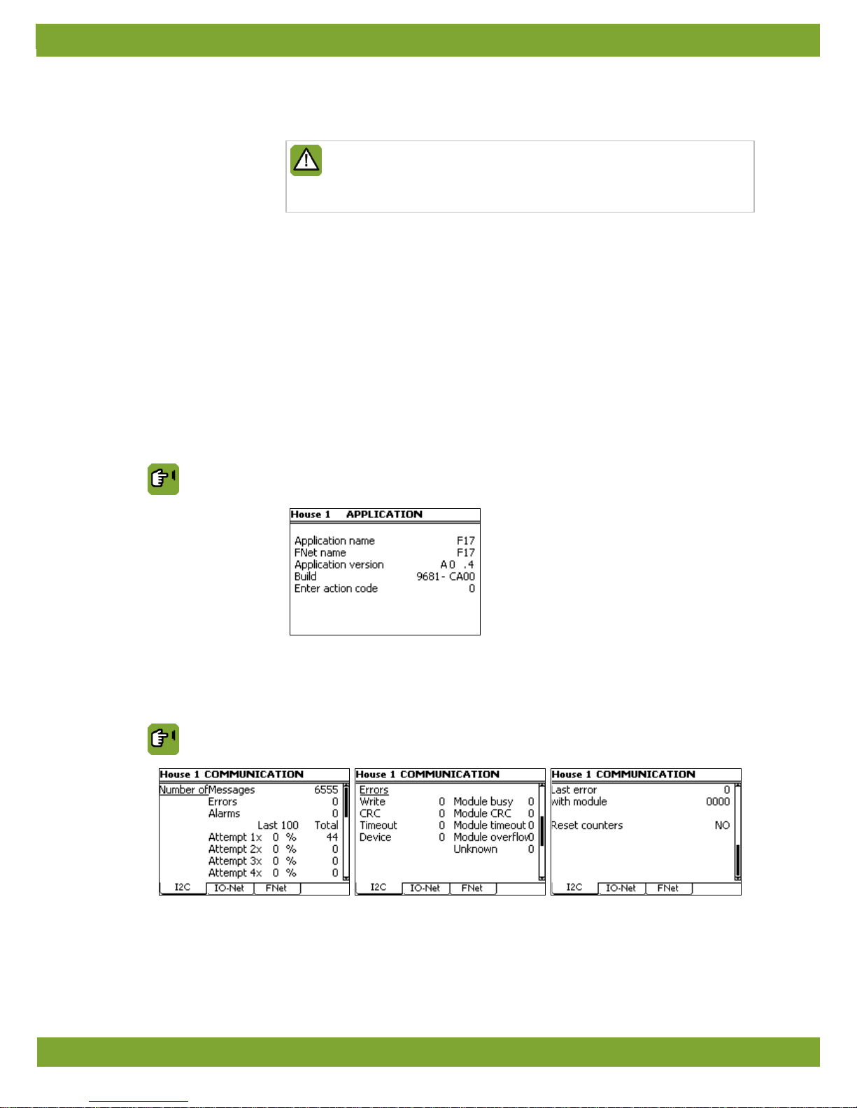
SYSTEM SD Card Menu
Backup data
Backup data writes all the data set in the control computer to the SD-card (type .FBU). A
service engineer may require this data so the settings can be checked on a different
control computer.
Page 12
Lumina 40 System
8
Restore data
Restore data re-loads sav ed d at a fro m t he SD-
card back onto the co ntrol co mpu ter (ty p e
.FBU).
Data saved on one control computer can only be loaded into another control
computer if both computers are of the same type. In addition, the set control
computer numbers must be identical. If both thes e cond itions are not met,
loading will fail.
Backup FUNC Backup FUNC writes a copy of the operating system (type .FIN) from the control
computer to the SD-card.
Update FUNC Update FUNC loads an operating system (type .FIN) from the SD-card onto the control
computer. Select the required file using the + en – keys on the alpha-numeric keyboard.
Confirm using the ENTER key.
Update HI
Update HI
(HI = Human Interface) loads an oper ating syst em (ty pe .HIN) for th e keyboar d
and the screen from the SD-
card onto the control com puter. S elect t he require d fil e using
the + en – keys on the alpha-numeric keyboard. Confirm using the ENTER key.
4.3 Application
The application menu contains the data of the control computer.
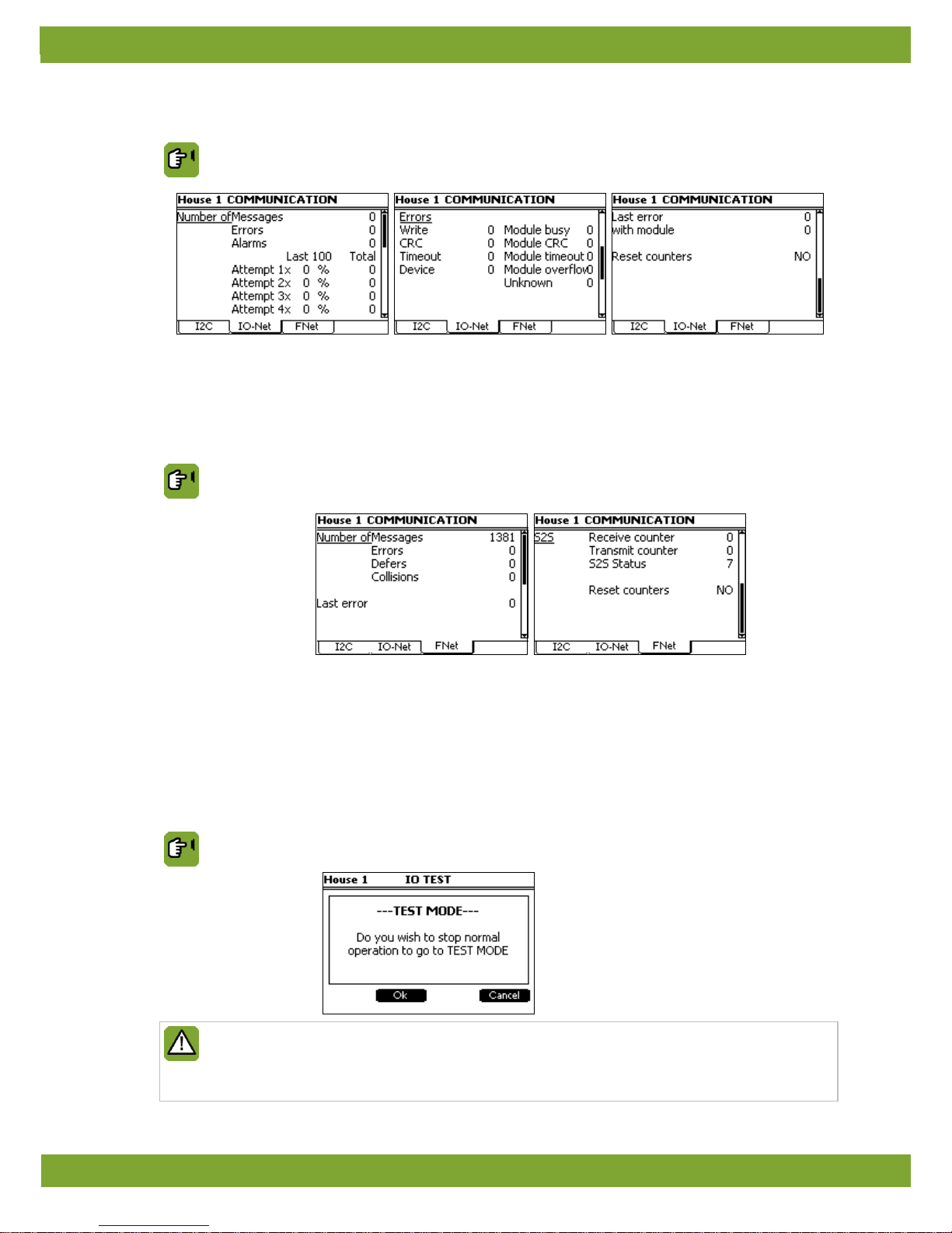
SYSTEM APPLICATION
4.4 Communication
I2C is a communication bus used to connect prints in the control computer (e.g. AI.4).
SYSTEM COMMUNICATION tab page I2C
Reset counters
Setting used to reset all data to zero simultaneously.
If there is no S2S communication, the Receive and Transmit counters should be set to 0.
Page 13
Lumina 40 System
9
The I/O net is a connection for i ntelligent networ k modules. For example, Intellig ent Relay M odules (IRM), Intelligent
Digital Modules (IDM) or Intelligent Sensor Modules (ISM).
SYSTEM COMMUNICATION tab page IO-Net
Reset counters
Setting used to reset all data to zero simultaneously.
If there is no S2S communication, the Receive and Transmit counters should be set to 0.
FNet is the Fancom Netw ork. S everal contr ol comput ers can be linked via this ne twork. FN et is a lso used t o operat e
the connected control computers from a connected PC.
SYSTEM COMMUNICATION tab page FNet
Reset counters
Setting used to reset all data to zero simultaneously.
If there is no S2S communication, the Receive and Transmit counters should be set to 0.
4.5 IO-Test
Use the Input (I) and Output (O) test menu to set the control computer to test the communication channels.
In the IO-test menu inputs can be readout and outputs controlled at system level
SYSTEM IO-TEST
The functions in the IO-t est menu stop all the control actions of the control computer. Only use this to
quickly test IO functions.
This function may only be used by qualified personnel, as parts of the installation may be damaged with
direct control.
Page 14
Lumina 40 House setup
10
5. House setup
This chapter explains all the options in the HOUSE SETUP menu.
In HOUSE SETUP select t he parts o f the control compu ter y ou inte nd to u se. T he contr ol co mputer will on ly dis play
data relevant to you in the screens. Parts not used, will not be shown. Most codes are self ex planatory .
5.1 Tab page Number
In tab page Number the number of silos and the use of external alarms can be entered.
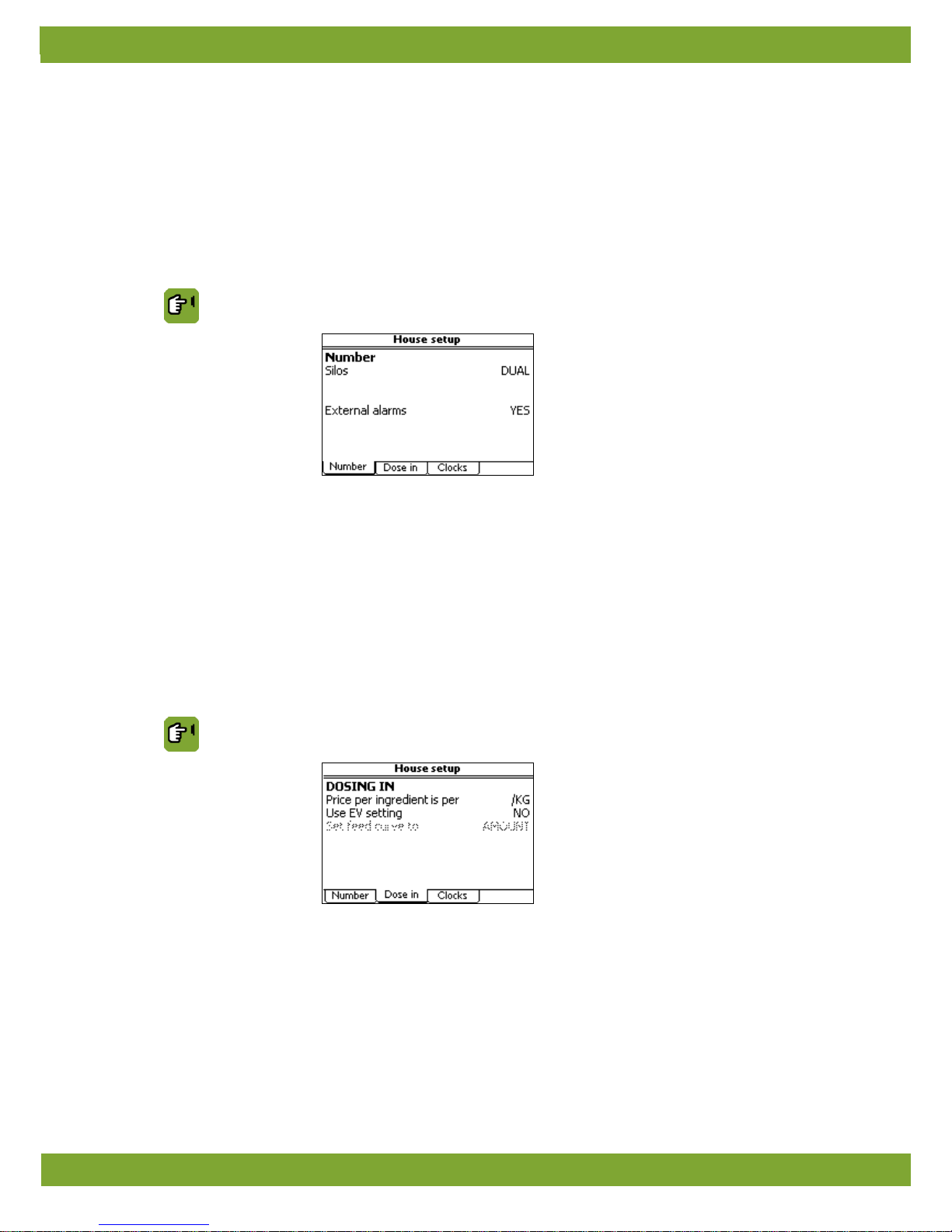
Installer HOUSE SETUP tab page Number
Silos
Setting indicating if a single silo (SIN GLE) or a frame w ith a double silo (DUAL) is used.
External alarms
Setting indicating if one or more external alarms are connected to the Lumina 40
(Select YES
). This allows a m enu to be access ed w here ex ter nal alar ms w ith the ir ow n
report message text can be set.
A few examples of external equipment with alarm options are door contacts, auger
motors or pressure alarm of a compressor.
5.2 Tab page Dose in/out
In the tab page “Dose in” data about feed can be set.
Installer HOUSE SETUP tab page Dose in
Price per ingredient is
per:
Setting of the unit for enterin g the pric es of f eed ingred ients. Price s can be enter ed per
KG, per 10 KG or per 100 KG.
Use EV settings Setting to show the energy value in the user's menu. Select YES
if the energy value is
to be shown on the screens in the user's menu.
Set feed curve to
Setting indicating if the data in the feed curves must be entered based on amount
(AMOUNT) or on energy value (EV).
Page 15
Lumina 40 House setup
11
5.3 Tab page Clocks
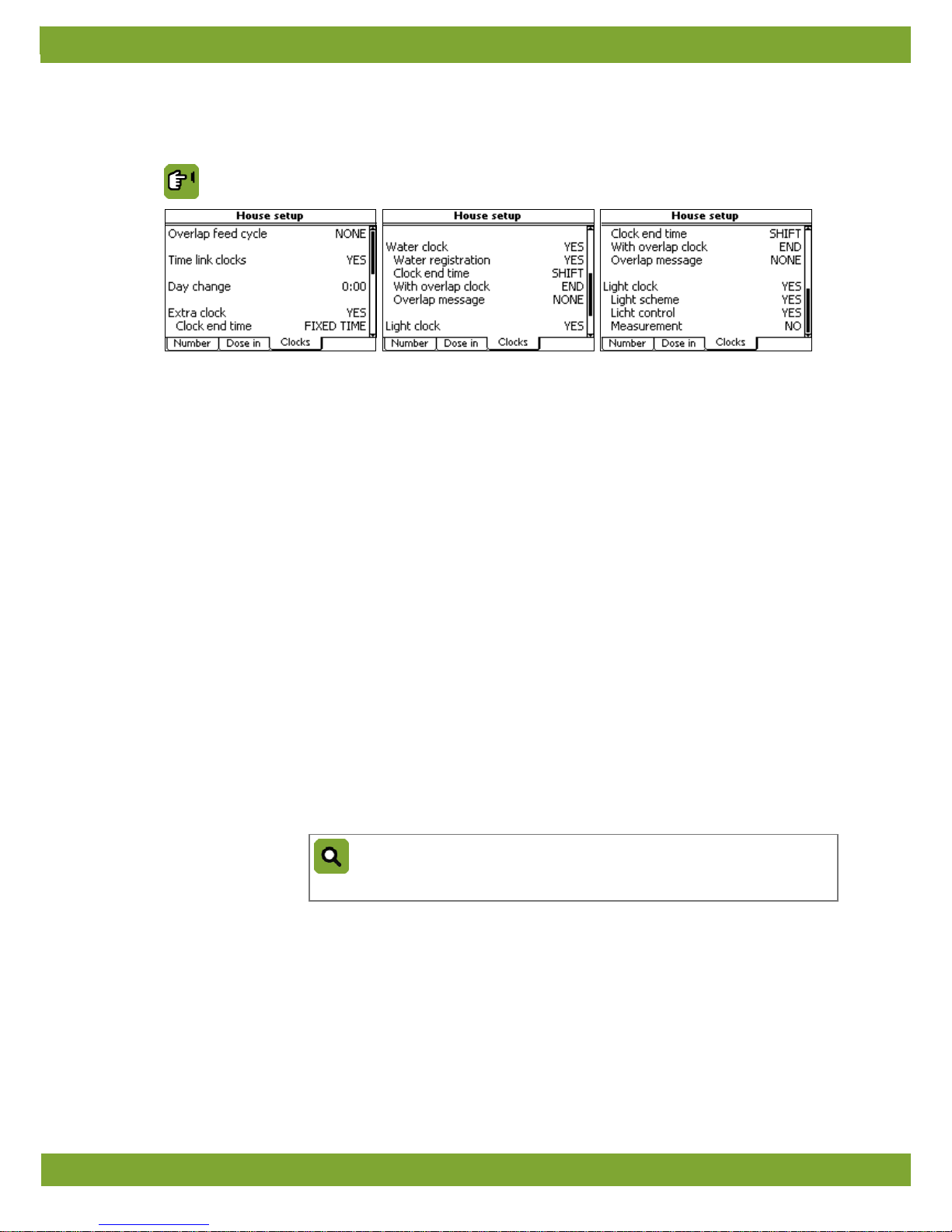
In the tab page Clocks set which clocks are used, how they are linked and what must ha ppe n if there is an overl ap .
Installer HOUSE SETUP tab page Clocks
Overlap feed cycle
Setting of the control computer control if the end time overlaps the start time of the next
feeding cycle (for example, after a power failure):
• NONE
: The control computer d oes not giv e a message and pr oceeds accord ing to th e
normal feed process with overlap.
• STOP: The control computer stops the feed process and gives a loud alarm.
• LOUD: The control computer gives a loud alarm and proceeds according to the
normal feed process with overlap.
• SILENT: The control computer gives a silent alarm and proceeds according to the
normal feed process with overlap.
Time link clocks
Setting indicating if the cl oc ks are linked.
For example, the light clock is linked to the feed clock. The lighting is switched on 15
minutes before feeding starts and switches off 30 minutes after feeding stops.
Day change
Setting of the time of the day change.
Many tasks depend on a day change, such as starting feeding cycles or time clocks, and
data registration. The day change is used as follows:
• Daily data registration
• Each day begins and ends at the time of the day change.
• If the last feeding cycle is still active when the day change is reached, the control
computer will not interr upt this f eeding cycle.
The day change w ill only take place after
the feeding cycle has been completed.
Example: Day change
You have set the day ch ang e t o 02: 00 a.m. As a result, the t
ime period of every
‘registration day’ is from 02:00 to 01:59 h.
Extra clock
Water clock
Light clock
Setting if you use the extra clock, feed clock and the water clock.
• The Water clock is used to control the water in the house.
• The Light clock is used to activate/deactivate the lighting.
• The Extra clock can be used to control another process in the house.
Page 16

Lumina 40 House setup
12
Clock end time
(With Extra clock and
Water clock)
Setting indicating that the control computer can shift the end time of a clock, for example,
after a power failure.
• NO TIME: The clock has no fixed end time. After a power failure the end time is one
minute before the next start time.
• FIXED TIME: The control computer does not shift this end time. The clock observes
the set end time (therefore the current feeding cycle will be shorter).
• SHIFT
: The control computer can shift the end time up to a maximum of the end time
of the following time period. If this setting is selected the extra settings With clock
overlap and Overlap message will appear.
With overlap clock
(With Extra clock and
Water clock)
Setting indicating the action the control computer must take if the end time of a period
shifts, and overlaps the start time of the next time period (see Clock end time).
• END: The control computer deactiv ates the time clock if the end t ime overlaps t he sta
rt
time of the next period.
• SHIFT: The control computer does not dea ctivate t he ti me clo ck.
The next time period
is moved up (shifted).
Overlap message
(With Extra clock and
Water clock)
Setting indicating the action the control computer must take if one time per iod ov erlap s
another:
• NONE: The control computer sends no message and completes the current feeding
cycle.
• STOP: The control computer stops the feed process and gives a loud alarm.
• LOUD: The control computer gives a loud alarm and completes the current feeding
cycle.
• SILENT
: The control computer giv es a silen t alar m an d co mp lete s the c urr en t feed ing
cycle.
Water registration
Setting indicating if the amount of water must be registered. A connected water meter is
required. Enter the water meter data at registration page 25.
Light scheme
Setting indicating if the user uses light schemes.
Light control
Setting indicating if the user wants to control light as a percentage.
Measurement
Setting indicating if light measurement in the house is used.
Page 17
Lumina 40 Silos and ingredients
13
6. Silos and ingredients
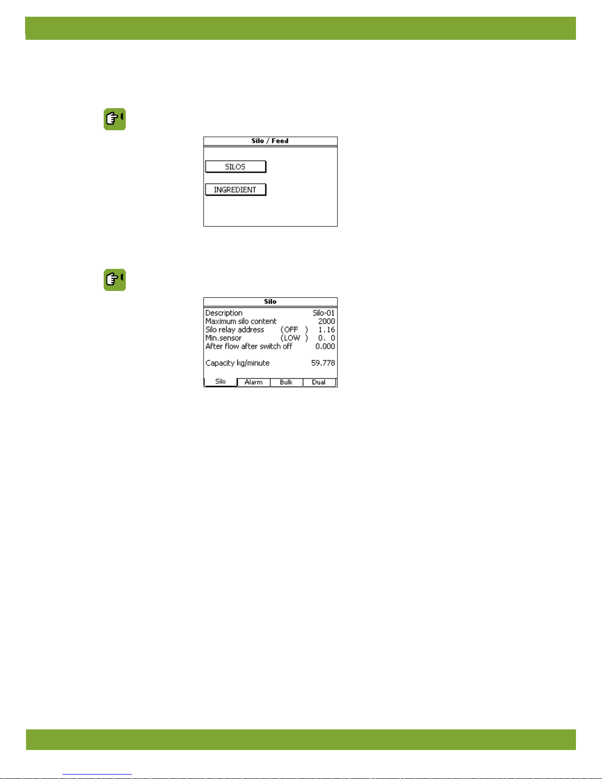
In the silos and ingredient menu enter the basic data of the silo(s) and feed ingredients used.
Installer SILO/INGRED.
6.1 Tab page Silo
Installer SILO/INGRED. SILOS. tab page Silo
Description
Setting of the name of the function.
Maximum silo content
Setting of the maximum silo content ( kilograms).
Silo relay address
Setting of the address of the digital output (relay) of the outgoing silo auger.
The value between brackets (OFF)/(ON) indicates the actual auger status.
Min. sensor
Setting of the digital input address for empty silo detection.
After flow after switch off
Readout of the after flow value.
The after flow does not need to be set: the control computer auto matically calculates
this. The after flow can b e set t o z er o (0), the after flow will then be recalculated dur i n g
the next following dos ing in sessi on. The afte r flow w ill be correcte d to the new v alue i n
one go.
Capacity kg/minute
Setting of the amount of ingredient that can be dosed out in one minute.
Page 18
Lumina 40 Silos and ingredients
14
6.2 Tab page Alarm
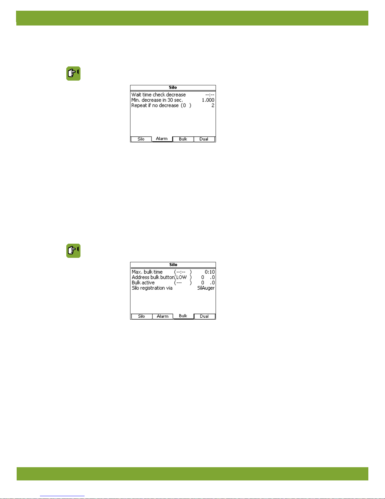
Installer SILO/INGRED. SILOS. tab page Alarm
Wait time check
decrease
Setting of the wait time af ter which the check on t he minimu m amount of decrease ( Min
decrease in 30sec.) starts.
Min decrease in 30sec.
Setting of the minimum required weight decrease in 30 seconds that must be
measured.
Repeat if no decrease
Setting of the number of ti mes that t he co ntrol co mputer mu st restart a dosin g process.
The value between brackets in dica tes t he n umb er of t ime s a re-
start has already been
tried.
6.3 Tab page Bulk
Installer SILO/INGRED. SILOS. tab page Bulk
Max.BulkTime Setting of the Max.BulkTime.
If the bulk button is activated, the feed registration will be registered based on auger
capacity and not on silo weight. As l ong as the inpu t is HIGH, t he time will repe atedly be
initiated according to the set time. At the moment that the input is LOW, the remaining
time will be repeatedly decreased to 0. Registration will then be based on silo weight
again.
Address bulk button
Setting of the bulk button address to the silo (Digital Input).
The value between brackets indicates the actual bulk status.
Bulk Active
Setting of the address of the relay to switch the LED belonging to the bulk button
indication.
Silo registration via
Setting of the registration input to which the feedback of motor running time of the
transport auger is sent to. The standard name of this registration is SilAuger.
Page 19
Lumina 40 Silos and ingredients
15
6.4 Tab page Dual
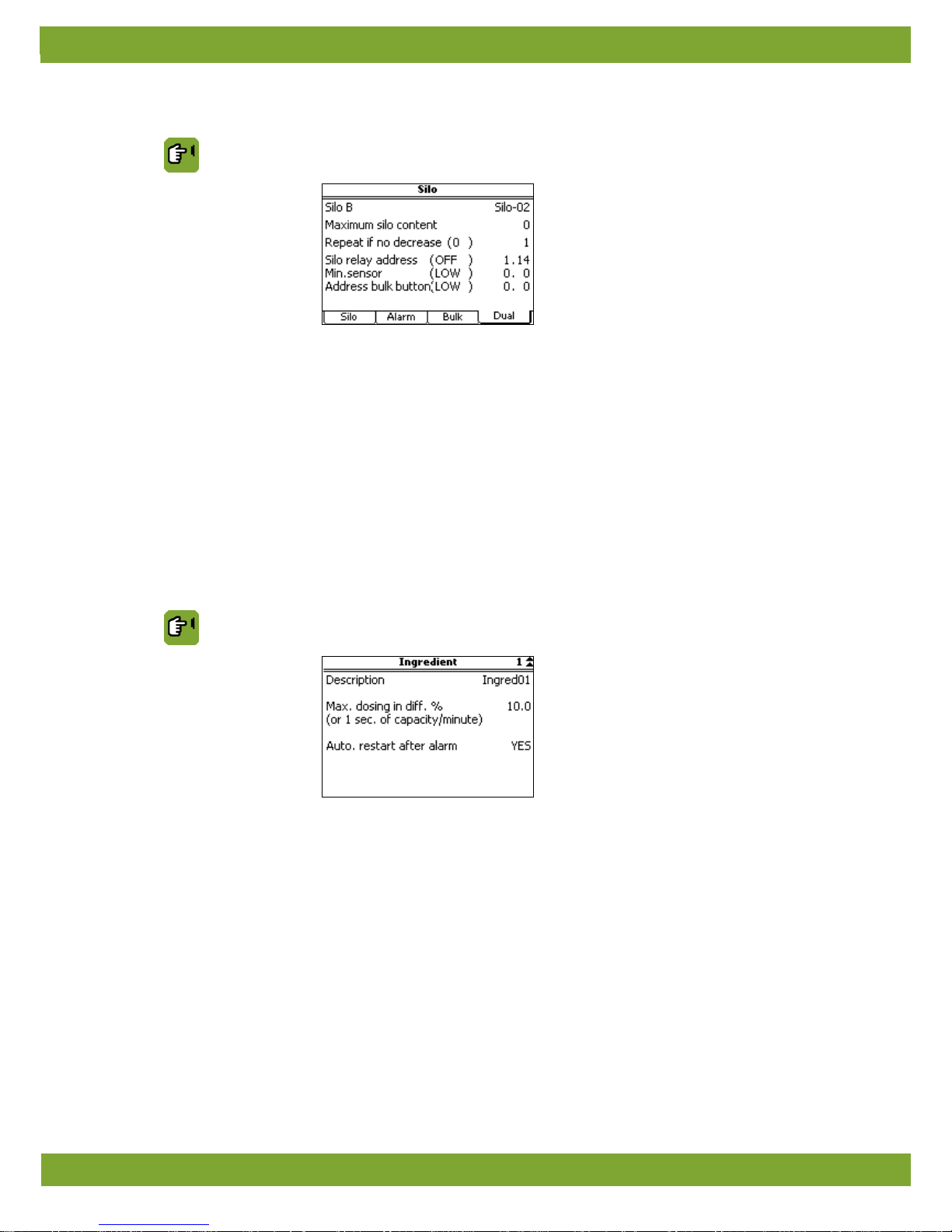
Installer SILO/INGRED. SILOS. tab page Dual
Maximum silo content
Setting of the maximum silo content ( kilograms).
Silo relay address
Setting of the address of the digital output (relay) of the outgoing silo auger.
The value between brackets (OFF)/(ON) indicates the actual auger status.
Min.sensor
Setting of the digital input address for empty silo detection.
Address bulk button
Setting of the bulk button address to the silo (Digital Input).
The value between brackets indicates the actual bulk status.
6.5 Ingredients
Enter the standard data of the various feed ingredients here.
Installer SILO/INGRED. INGREDIENTS
Description
Setting of the name of the ingredient concerned.
Max. dosing in diff.%
(or 1 sec. of
capacity/minute)
Setting of the maximum permitted dosing difference.
Min. stock alarm
Setting of the minimum stock alarm is required.
Page 20
Lumina 40 Weigher
16
7. Weigher
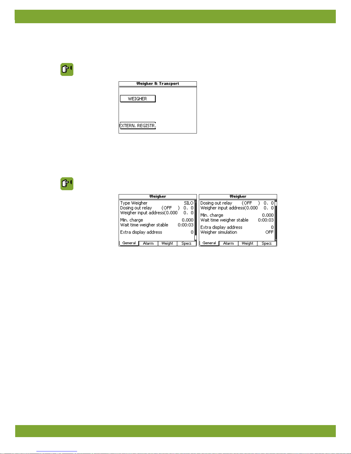
In the weigher menu enter the basic data for the weigher used.
Installer WEIGHER
7.1 Weigher
7.1.1 Tab page General
Installer WEIGHER tab page General
Type weigher Setting of the type of weigher used. SILO is the standard Fancom weigher.
Dosing out relay
Setting of the relay used to control the weigher valve. The value between brackets
indicates the current status.
Weigher input address
Setting of the input address to which weighing is connected. This input converts a
weighing signal into counts. The computer converts the counts into a weight.
Address 0 is a built in address and address 1..30 is an external w eighin g card.
Min. charge
Setting of the minimum weight that can be dosed in. The control computer will not make
any portions smaller th an t his amou nt. This can be important if a certa in min im um weight
is required to open the weigher valve.
Wait time weigher stable
Setting of the wait time after which the control computer determines the weight. This
allows the control computer to determine the w eight more a ccurately. T his applies t o both
the dosed
in weight and the zero point of the weigher after it has been emptied. The wait
time applies from the moment the auger is deactivated or the valve is closed.
Extra display relay
Setting of the relay address for using an external display.
Page 21
Lumina 40 Weigher
17
Weigher simulation Setting used only for test purposes to set the weigher to simulation mode. Select ON to
start simulation mode.
The following can be set in simulation mode:
• Simulation mode to simulate the weigher input. Select Stable, None, Increase or
Decrease. The simulated weigher then reacts according to the mode set.
• Increase in counts
indicates the number of counts simulated with a closed valve per
second.
• Decrease in counts
indicates the number of count s simul ated with an open v alve pe r
second.
The weigher does not work in this mode!
7.1.2 Tab page Alarm
The alarm settings below apply to all weigher types:
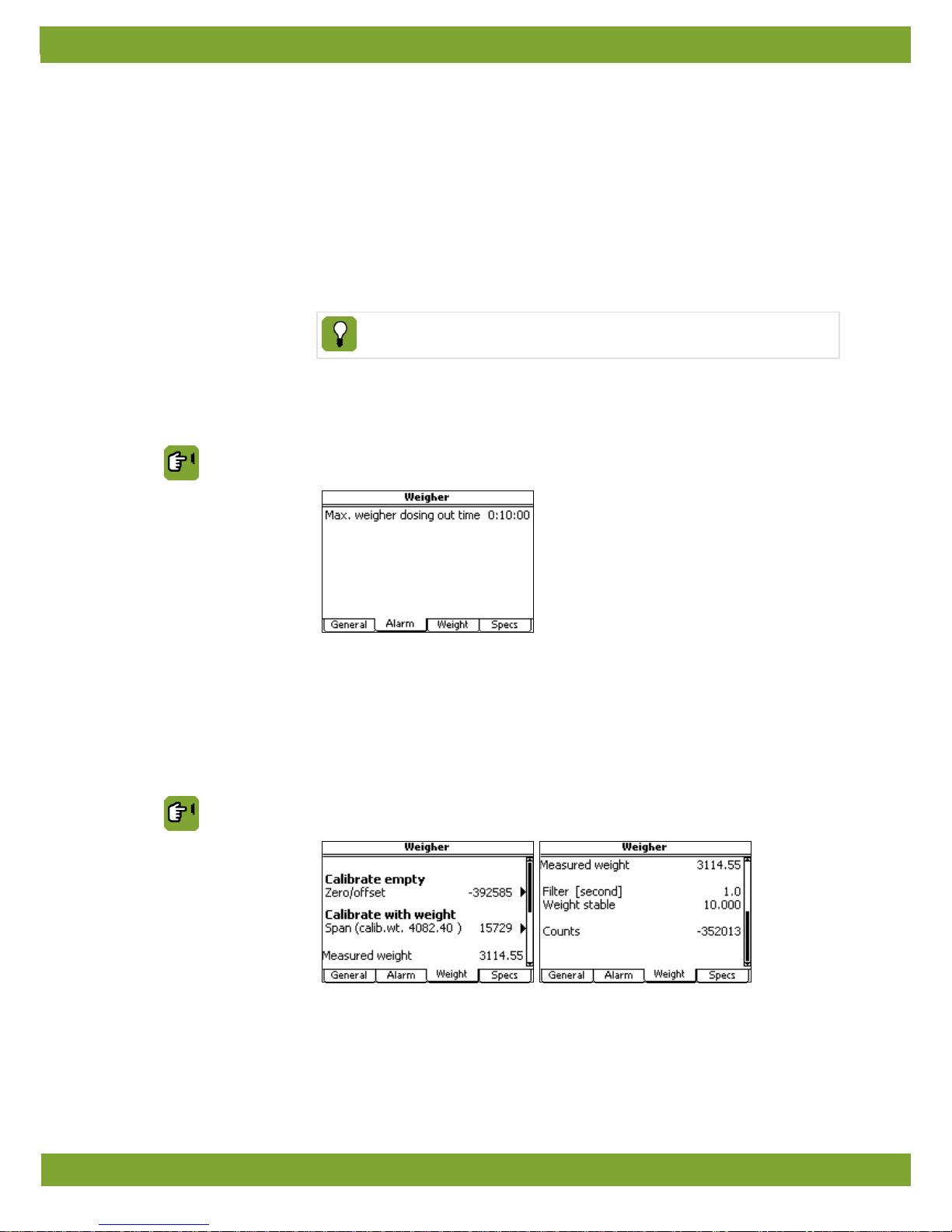
Installer WEIGHER tab page Alarm
Max. weigher dosing out
time
Setting of the time within which, after the first demand, the de mand s ens or mu st
report
full at least once.
7.1.3 Tab page Weight
After installation, the weigher must be calibrated and adjusted. Use the functions on this tab page. These settings
apply to all weigher types.
Installer WEIGHER tab page Weight
Page 22

Lumina 40 Weigher
18
Calibrating silo weighing
After the weigher has been installed, it must be calibrated. This allows the control
computer to determine the feed weight more accurately. The weigher transmits a
measured weight in the f orm of v alues as c ounts to th e control computer. By cali brating
the control computer, this pulse value can be converted correctly into a weight.
If the data under tab page Specs has been entered correctly, it should not be
necessary to calibrate using a weight. Calibrating empty should be sufficient.
To calibrate the weigher, a calibration weight is required. Use a calibration weight that
is nearly as heavy as the maximum empty weight of the weigher/blender.
Calibrate the weigher as follows
1. Empty the weigher completely so the control computer can determine the zero
point.
2. Select CALIBRATE EMPTY.
3. Press Ready to identify the zero point of the weigher .
Tab page Weight will ap pear again. Zero/off set show s the number of counts of the
zero point. Place a sufficiently heavy calibration weight in the weigher.
4. Select CALIBRATE with weight.
5. Enter the Calibration weight in the screen that appears. Press Ready to calibrate
the weigher with this weight.
Tab page Weight will appear again. Span
will show the calibration weight with the
corresponding number of counts.
Setting weigher accuracy
When the weigher has been calibrated, de term ine weigher accuracy and carry out any
further weigher
calibration. The control co mp uter u ses t he se tt ing s bel ow to det ermi ne
when a measurement is reliable.
Filter (second)
Setting of the period within which the measured weight must be stable within the limits
of the entered differences (Weight stable).
Weight s table Setting of the value of Weight stab le (in KG).
Within the Filter time the difference between the highest and lowest weight must not
exceed Weight stable. If the alarm message ‘weigher not stable’ appears, this value
can be increased.
Counts
Readout of the actual number of counts currently being read on the input.
Page 23
Lumina 40 Weigher
19
7.1.4 Tab page Specs
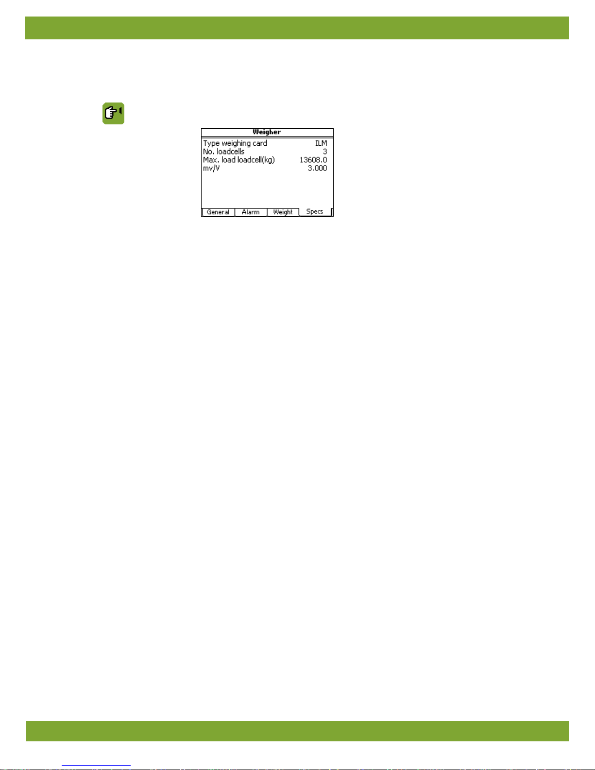
Installer WEIGHER tab page Specs
Type weighing card Setting of the type of weigher amplifier being used. ILM, LCC or OTHER.
Number of load cells
Setting of the number of connected load cells.
Max load load cell
Setting of the maximum weight which can be loaded on the load cell. This is usually
stated on the indication plate of each load cell.
mv/V
Setting of the amplification of the load cell signal per offered excitation vol tage .
This value is usually stated on the indication plate of each load cell
If OTHER has been selected at Type weighing card, the data fields below will appear.
Max. mV module
Setting of the input voltage used by the connected weigher amplifier to readout its
maximum number of counts.
Max. counts module
Setting of the maximum number of weigher amplifier counts that may be readout.
Excitation voltage(V)
Setting of the nominal voltage to which the weigher amplifier is connected.
Page 24
Lumina 40 Weigher
20
7.2 External registration
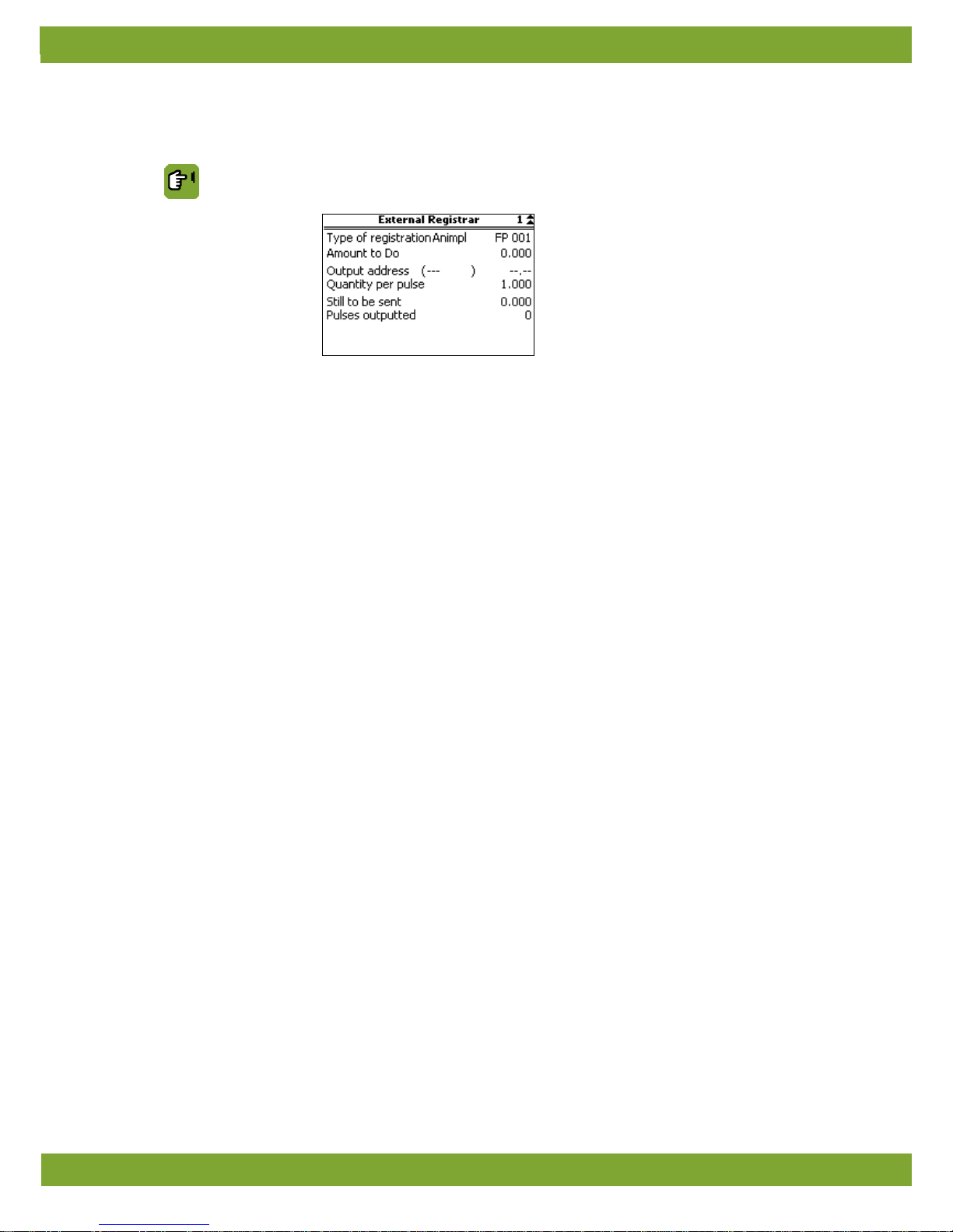
Installer WEIGH/TRANSP. EXTERN.REGISTR.
Type of registration
Setting of the registration type being used:
• Animpl: Registration per animal place.
• Sect: Registration per section.
Amount to Do
Read out of the total amount of pulses to be sent.
Output address
Setting the address of the relais used for pulsing.
Quantity per pulse
Setting of how many grams per pulse are measured.
Still to be sent
Read out the amount of pulses to be sent.
Pulses outputted
Read out of the amount of sent pulses.
Page 25
Lumina 40 Feed place
21
8. Feed place
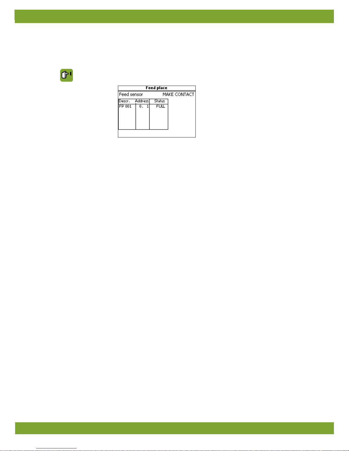
In the feed place menu enter per house t h e d ata f or the feed places used ( hoppers) and the se nsor in sta lle d i n the
final hopper.
Installer Feed place
Feed sensor
Setting of the type of sensor:
• Make contact: The sensor ma kes cont ac t if it detects feed .
• Break contact: The sensor breaks contact if it detects feed.
Address
Setting of the address of the digital input.
Page 26
Lumina 40 Clocks, external registration and alarms
22
9. Clocks, external registration and alarms
In the clocks and registration menu enter the settings for the clocks used per house. In the menu HOUSE SETUP
the clocks to be used have already been entered. The data for these clocks can be set here.
At registration enter the data for the registration input.
At external alarms messages and other data can be entered for the connected external alarm contacts.
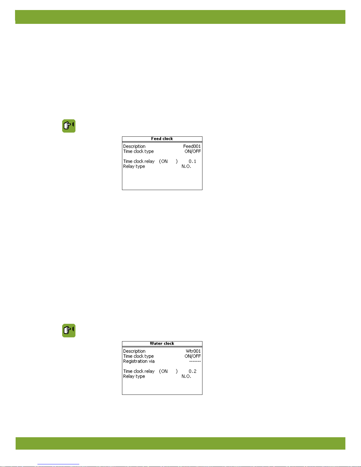
9.1 Feed clock
The feed clock is used to prepare feed (dosing in, weighing and dosing out) and to control the feed lines.
Installer CLOCK / REGIS. FEED
Description
Setting of the name of the function.
Time clock type
Setting indicating how the user can use the clock:
• ON/OFF: User enters on/off times.
• ON/DURATION: User enters time and duration of activation.
Time clock relay Setting for the analogue output address (choice LINEAR) or relay output (choice
RELAY).
Relay type
Setting of the passive (not controlled) relay status.
• N.O. (normally open) if it makes no contact.
• N.C. (normally closed) if it makes contact.
9.2 Water clock
The water clock is used to control the water supply in the house. One water clock can be used per house.
Installer CLOCK / REGIS. WATER
Page 27
Lumina 40 Clocks, external registration and alarms
23
Description
Setting of the name of the function.
Time clock type
Setting indicating how the user can use the clock:
• ON/OFF: User enters on/off times.
• ON/DURATION: User enters time and duration of activation.
Registration via
Setting of the registration input used to measure the amount of water. The volume of
water can be measured by a flow meter.
Time clock relay
Setting of the relay address controlled by the clock.
Relay type
Setting of the passive (not controlled) relay status.
• N.O. (normally open) if it makes no contact.
• N.C. (normally closed) if it makes contact.
9.3 Light clocks
Light clocks are used to control the light intensity in the house.
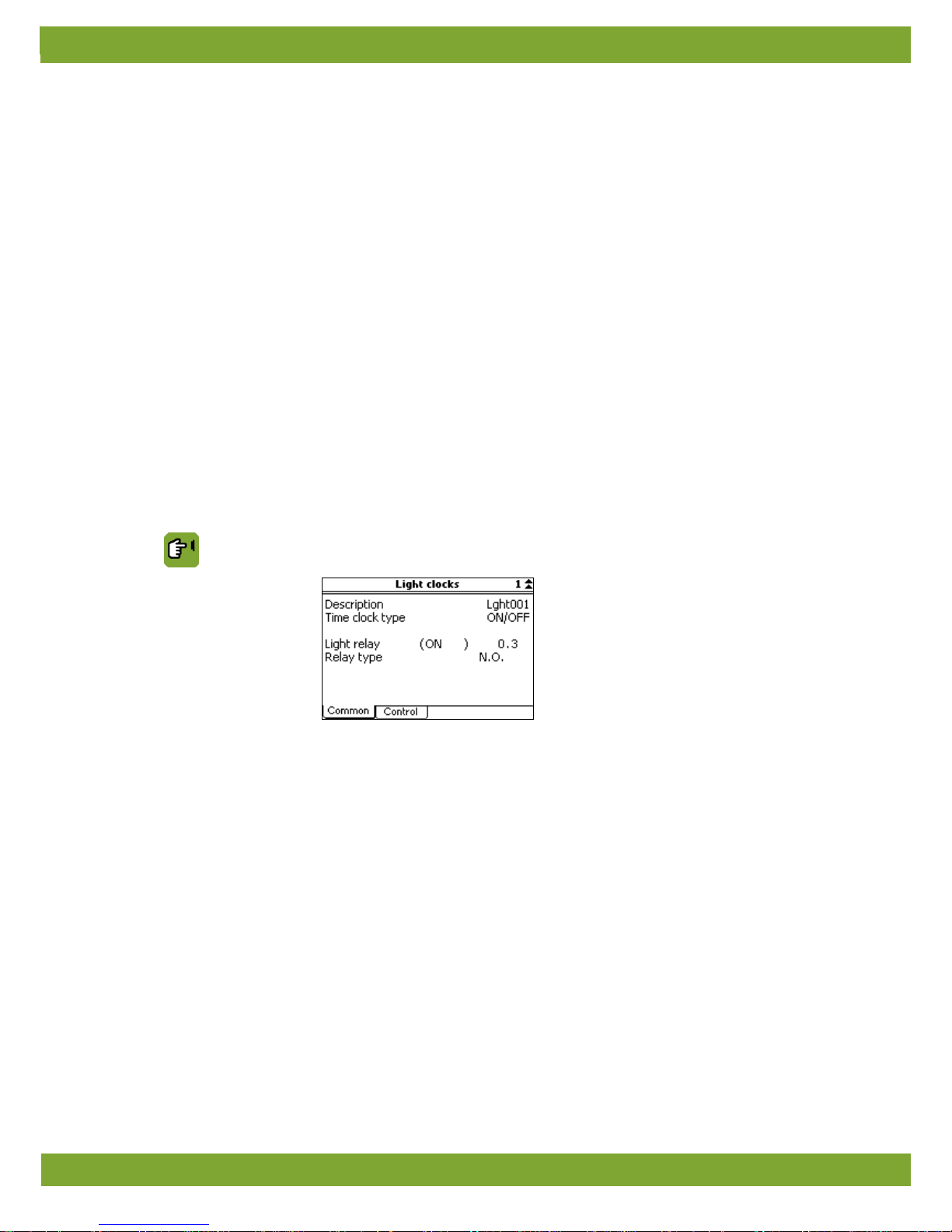
9.3.1 Tab page Common
Installer CLOCK/REGIS. LIGHT tab page General
Description
Setting of the name of the function.
Time clock type
Setting indicating how the user can use the clock:
• ON/OFF: User enters on/off times.
• ON/DURATION: User enters time and duration of activation.
• INTERMIT: Intermittent repeat clock. An intermittent light clock can be used to
periodically repeat a certain light pattern. For example, at the beginning of each
hour the lights can be controlled on for 15 minutes, then switched off for the other
45 minutes. Enter the required time settings in the user's menu.
Light relay
Setting of the digital out put address (relay) that controls the li ghting. T his relay switches
the light on and off and can also be used to overrule the control in percent ( analog
output
). This is important in order to switch off the lighting completely if the light level,
for example, falls below a certain level (Rel ay off below).
Relay type
Setting of the passive (not controlled) relay status.
• N.O. (normally open) if it makes no contact.
• N.C. (normally closed) if it makes contact.
Page 28
Lumina 40 Clocks, external registration and alarms
24
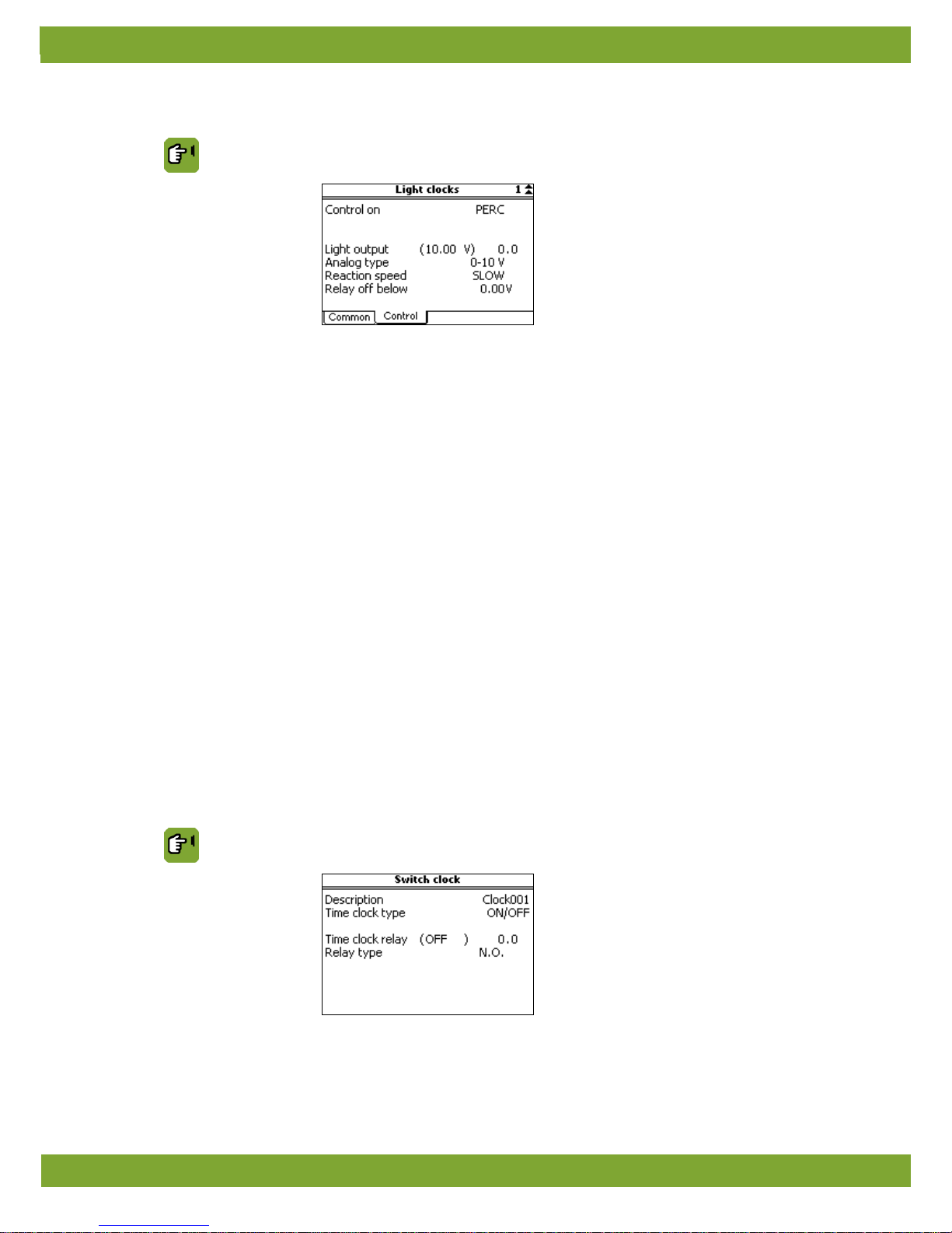
9.3.2 Tab page Control
Installer CLOCK/REGIS. LIGHT tab page Control
Control on Setting of the way in which light is controlled. This option is only available if light
measurement=YES has been selected at light clocks.
• LUX: If you want to control the light u sing a light sen sor, select LUX
. The light clock
will adjust the light intensity to the measured light intensity.
• PERC: If the lighting is not to be controlled using the connected sensor, select
PERC. The data from the light sensor will only be used for readout purposes.
Light measurement input
*
Setting of the input address (analog input ) to which the light s ensor u sed i s con nect ed .
This option is only available if on HOUSE SETUP tab page Clocks option light
measurement=YES was selected.
Light output
Setting of the analog output address used to control the light intensity in percentages.
Analog type
Setting indicating the analog control type
Reaction speed
Setting of the reaction speed of the light sensor that controls light intensity if the
measured light level changes (FAST, NORMAL or SLOW).
Relay off below
Setting of the threshold value below which the relay output deactivates the lighting if
control is based on a percentage (Dim
). This prevents an insufficient reaction from the
lighting below a certain percentage (flickering).
9.4 Extra clock
The extra clock can be used to switch external equipment. One extra clock can be used per house.
Installer CLOCK / REGIS. WATER
Page 29
Lumina 40 Clocks, external registration and alarms
25
Description
Setting of the name of the function.
Time clock type
Setting indicating how the user can use the clock:
• ON/OFF: User enters on/off times.
• ON/DURATION: User enters time and duration of activation.
Time clock relay Setting for the analogue output address (choice LINEAR) or relay output (choice
RELAY).
Relay type
Setting of the passive (not controlled) relay status.
• N.O. (normally open) if it makes no contact.
• N.C. (normally closed) if it makes contact.
9.5 Registration
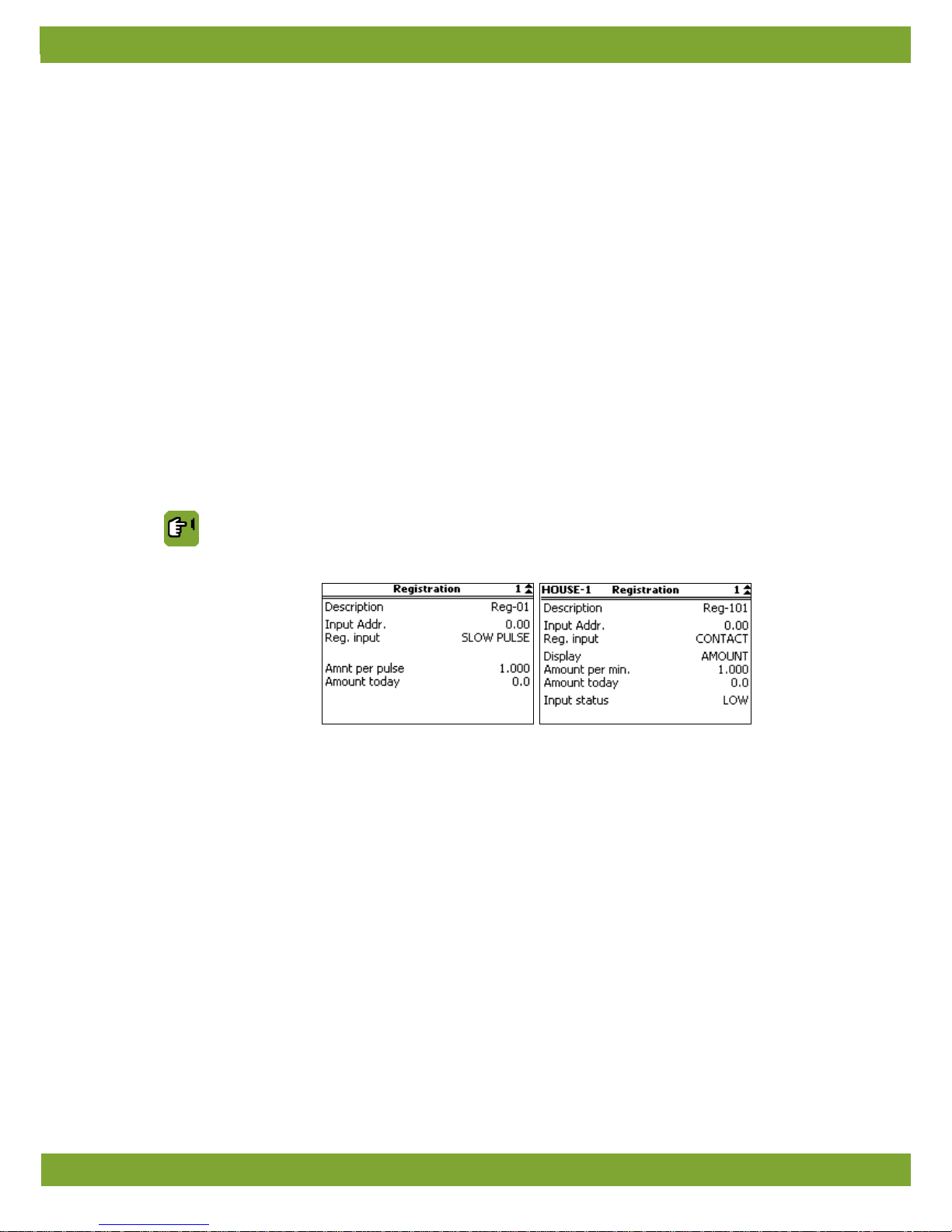
Per house, the control computer has an input that can be used to register water consumption.
The amount is register ed in th e f or m of pulse values (coun ts) or con tact . The control compu ter a dds up the number
of counts or measures the activ e time and co nverts the time into a measured amount. E nter in the r egistrati on menu
per house how the measured data can be read in.
Installer CLOCK / REGIS. REGISTRATION
Depending on the registration input type one of the following menus will appear:
Description
Setting of the name of the function.
Input Addr.
Setting of the address of the digital input.
Reg. input
Setting the type of measurement:
• MANUALLY: Enables you to enter the amount of today manually.
• SLOW PULSE: Measuring instruments with a maximum frequency of 20 pulses
per second (20 Hz).
• QUICK PULSE: Measuring instruments with a maximum frequency of 20 pulses
per second (20 Hz) (only use when there is a link with a switch clock).
CONTACT: As long as the sensor makes contact, the value will be added up
cumulatively. The amount is therefore determined by time the contact is HIGH.
Page 30
Lumina 40 Clocks, external registration and alarms
26
Depending on the selected Registration Input the following settings will appear:
SLOW PULSE or QUICK PULSE
Amnt per pulse
Setting of the unit that corresponds to one pulse.
Amount today
Readout of the unit measured today. Reset this value to start all registration from zero
again.
CONTACT
Display
Setting how the unit is displayed:
• AMOUNT: number 'units' per minute (Amount per min.).
• TIME: the time the contact makes contact.
Amount per min.
Setting of the number of 'units' measured per minute. This option is only available if
Display=AMOUNT.
Amount today
Readout of the unit measured today. Reset this value to start all registration from zero
again.
Input status Readout of the actual input status. HIGH or LOW.
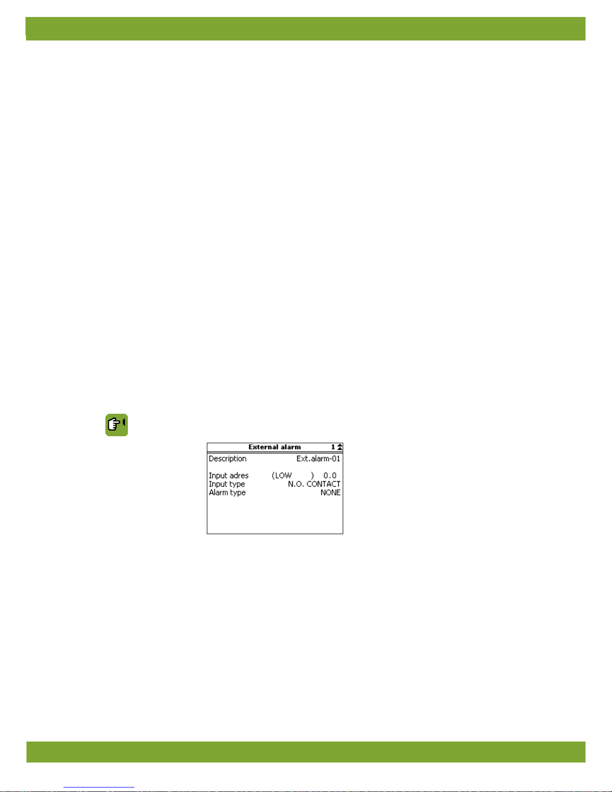
9.6 External alarms
The control computer has inputs to which external alarms can be connected.
Installer CLOCK / REGIS. EXTERNAL ALARM
Description
Setting of the alarm message shown with an alarm This text will appear each time an
alarm occurs.
Input address
Setting of the input address to which the alarm is connected. The value between
brackets indicates the current value of the input.
Input type
Setting indicating when the input must give an alarm.
• MAKE CONTACT: the alarm will activate if contact is made.
• BREAK CONTACT: the alarm will activate if contact is broken.
Page 31

Lumina 40 Clocks, external registration and alarms
27
Alarm type
Setting of how alarms are handled.
• NONE: the alarm is deactivated.
• STOP
: in an alarm situation, the computer will carry out a stop, followed by a loud
alarm.
• LOUD: loud alarm.
• SILENT: silent alarm.
Page 32

Lumina 40 Checks and tests
28
10. Checks and tests
The installer can run a number of tests on the control computer to check the operation of the feeding system.
10.1 Weigher test
The working of the installation can be tested using a weigher simulation. Weigher simulation only simulates the
weigher's load cell(s).
The installation can be 'dry r un' tested - i.e. without feed . The installat ion runs just lik e during a normal fe ed pro cess,
but without using any feed. This can be used to test the weigher's load cell before the installation is actually used.
With a weigher test ensure:
• All the augers must be activated.
• If using a separate weigher Ensure no feed can enter the weigher.
• If the installation also contains a hopper, make sure you operate the sensor in the hopper at the right moment
(otherwise an alarm will occur).
Set the weigher test in the menu Installer WEIGHER tab page General, at Weigher simulation.
See Weigher page 16 for the settin gs.
Page 33
Lumina 40 Technical specifications
29
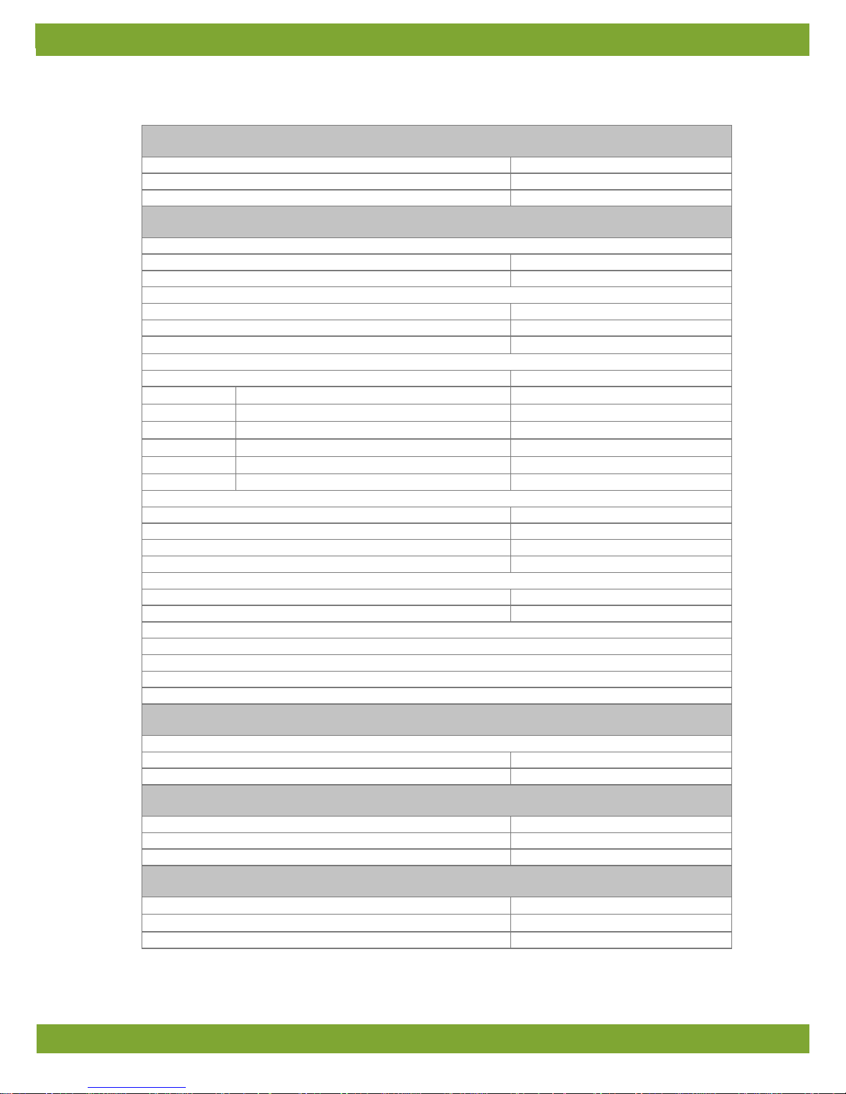
11. Technical specifications
FDP25
Mains voltage
90Vac – 264Vac
Main frequency
50/60Hz
Maximum power consumption
25VA
IOB.4
Power available for sensors and peripheral equipment
24Vdc (short circuit resistant)
max. 500mA
12Vdc, short circuit resistant
max. 70mA
4x analog outputs (AO)
Voltage range
0-10Vdc
Maximum load
1mA
Output resistance
570Ω
4x analog inputs (AI)
Types selectable via Jumper
resistance or voltage
Resistance:
Temperature range sensor type S.7
-50°C to +110°C
- accuracy (-25°C to +100°C)
<0.5°C
- accuracy (0°C to +60°C)
<0.2°C
Measuring range for position feedback
0-20kΩ
Voltage:
Measuring range (input resistance 100kΩ)
0-10Vdc
Accuracy
+/- 15mVdc
4x Digital inputs (DI)
Open contact voltage
12Vdc
Low level
<1.0Vdc
Application: Counter input, min. pulse width 25mSec
max. frequency 20Hz
Application: Frequency input
max. frequency 5kHz
5 Digital outputs (Relays)
Relays 1, 2, 3 (make & break contact) and 4: voltage free
max. 2A 60Vdc/30Vac
Relay 5 (alarm relay): voltage free
max. 2A 60Vdc/30Vac
Extra digital outputs (DO)
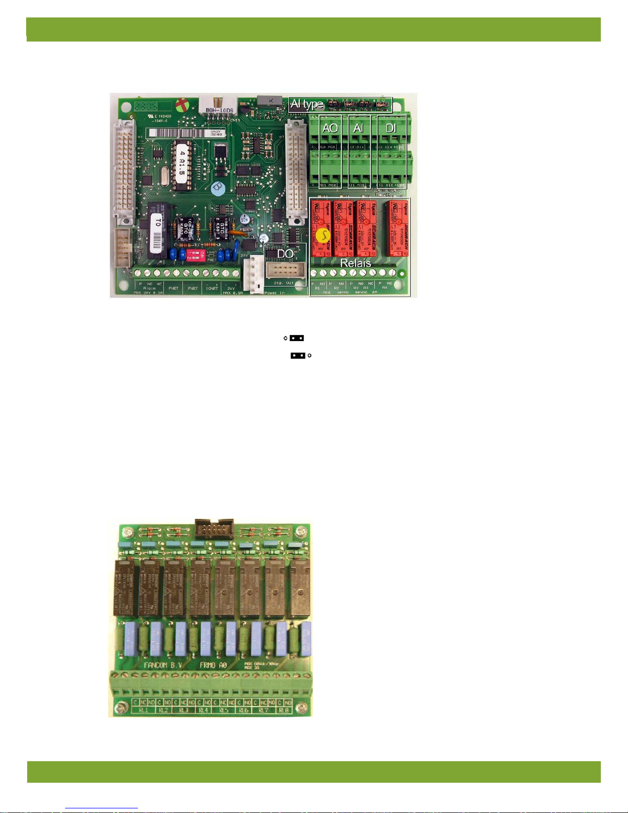
Connection for optional relay (FRM.8 print).
Communication
I/O-Net for extra inputs and outputs using I/O-modules.
FNet, Fancom network for intercommunication of control computers and PC connection.
FRM.8
8 Digital outputs (relays)
Relay 1, 3, 5, 7: make-and-break contact
Max. 2A 60Vdc/30Vac
Relay 2, 4, 6, 8: voltage free
Max. 2A 60Vdc/30Vac
Housing
Plastic housing with screw-on lid
IP54
Dimensions (l×w×h)
300×240×140mm
Weight (unpacked)
2.6kg
Ambient climate
Operating temperature range
0°C to +40°C
Storage temperature range
–10°C to 50°C
Relative humidity
< 95%, uncondensed
Page 34
Lumina 40 Technical specifications
30
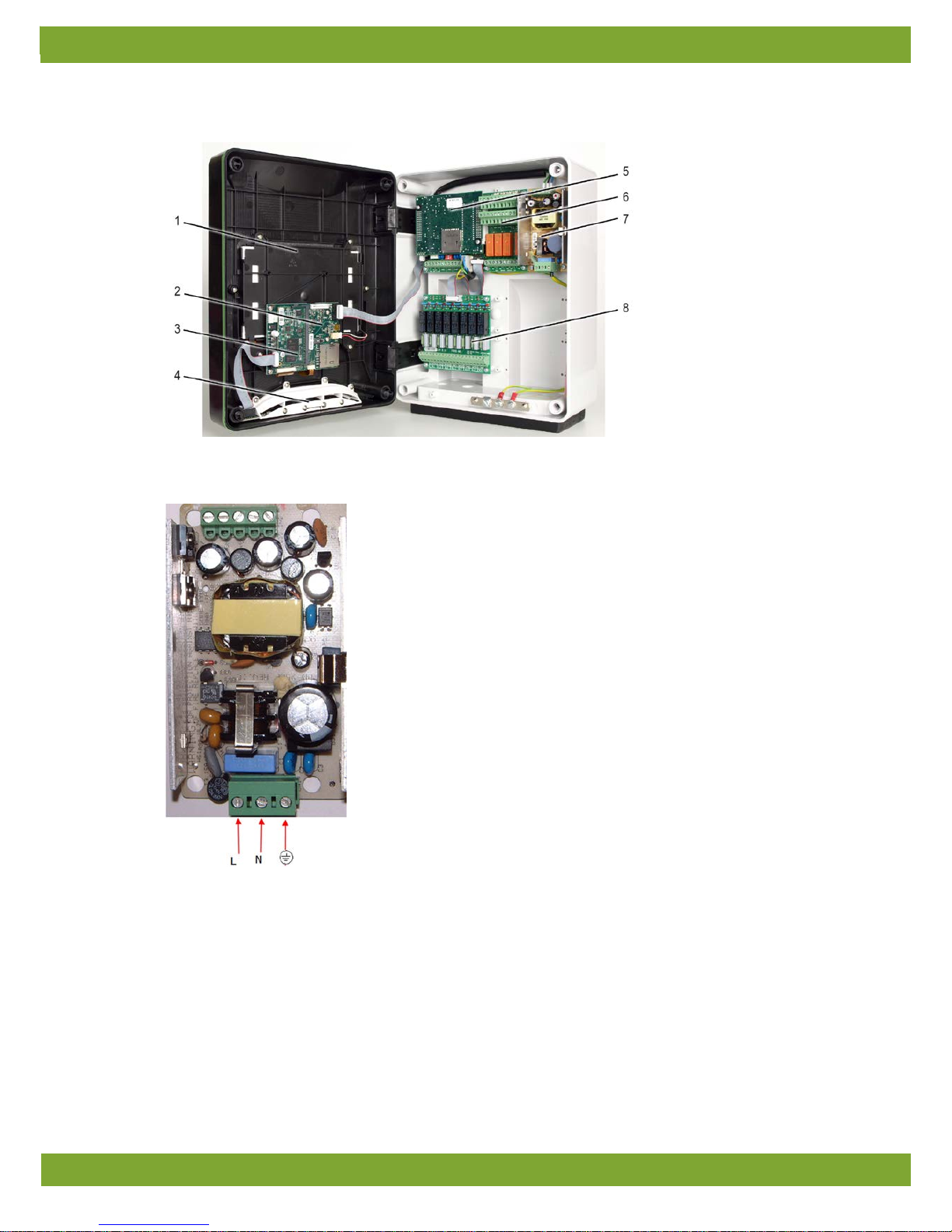
11.1 Interior control computer
1. Touch screen
2. HI mainboard
3. SBC
4. LED strip
5. FUNC (CPU)
6. IOB.4 (I/O)
7. FDP25 (Power supply)
8. FRM.8 (Internal relay)
11.2 FDP25
Page 35
Lumina 40 Technical specifications
31
11.3 IOB.4
AI type Type analog input
• Voltage measurement (U)
• Resistance measurement (R)
AO 4 Analog outputs
AI 4 Analog inputs
DI 4 Digital inputs
Relay 4 Digital outputs (relays)
DO 8 Extra digital outputs
11.4 FRM.8
Page 36
Lumina 40 Technical specifications
32
11.5 Connection FNet and I/O-net
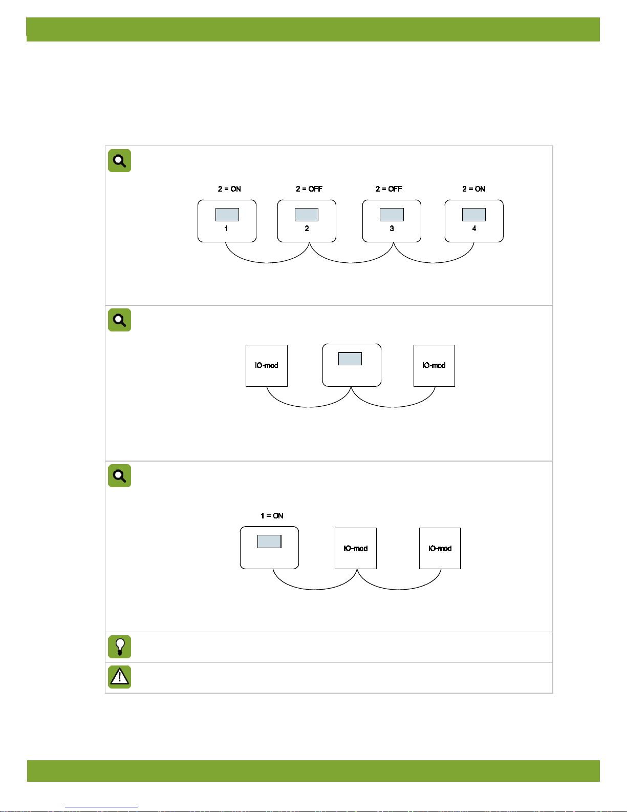
Use of the terminal resistor depends on the location of the control computer in the FNet or I/O network. Looped
control computers do not require a terminal resistor.
Control computers or end stations at the beginning or end of the network require a terminal resistor. Depending on
the device type a 120 Ohm resistance, a jumper or a dipswitch is used to terminate the control computer.
Example: Setting the terminal resistor FNet
Four control computers connected using FNet.
Control computers 1 and 4 are at the end of the network. These control computers must be terminated.
Control computers 2 and 3 are looped. These lo oped contro l computers do not requir e a term inal resist or.
Example: Setting the I/O-net terminal resistor (1)
One control computer connected to two I/0 network modules using one I/O-net.
The control computer is located between the two I/O network modules. This does not require a terminal
resistor.
Both I/O network modules are at the end of the network. These must be terminated.
Example: Setting the I/O-net terminal resistor (2)
One control computer connected to one network module using one I/O-net. This I/O network module is
linked to a second II/O network module.
The control computer and the second I/O network module require a terminal resistor.
The first I/O network module is looped. This does not require a terminal resistor.
The Fancom Greenlink
cable (UTP 1x2x0.8mm, unshielded twisted pair) used to wire the FNET and I/O
net. Maximum cable length = 1200 meters.
Connect each Fancom device according to the applicable legislation/regulations of the local energy
provider.
Page 37
Lumina 40 Appendix: Concept feeding system
33
12. Appendix: Concept feeding system
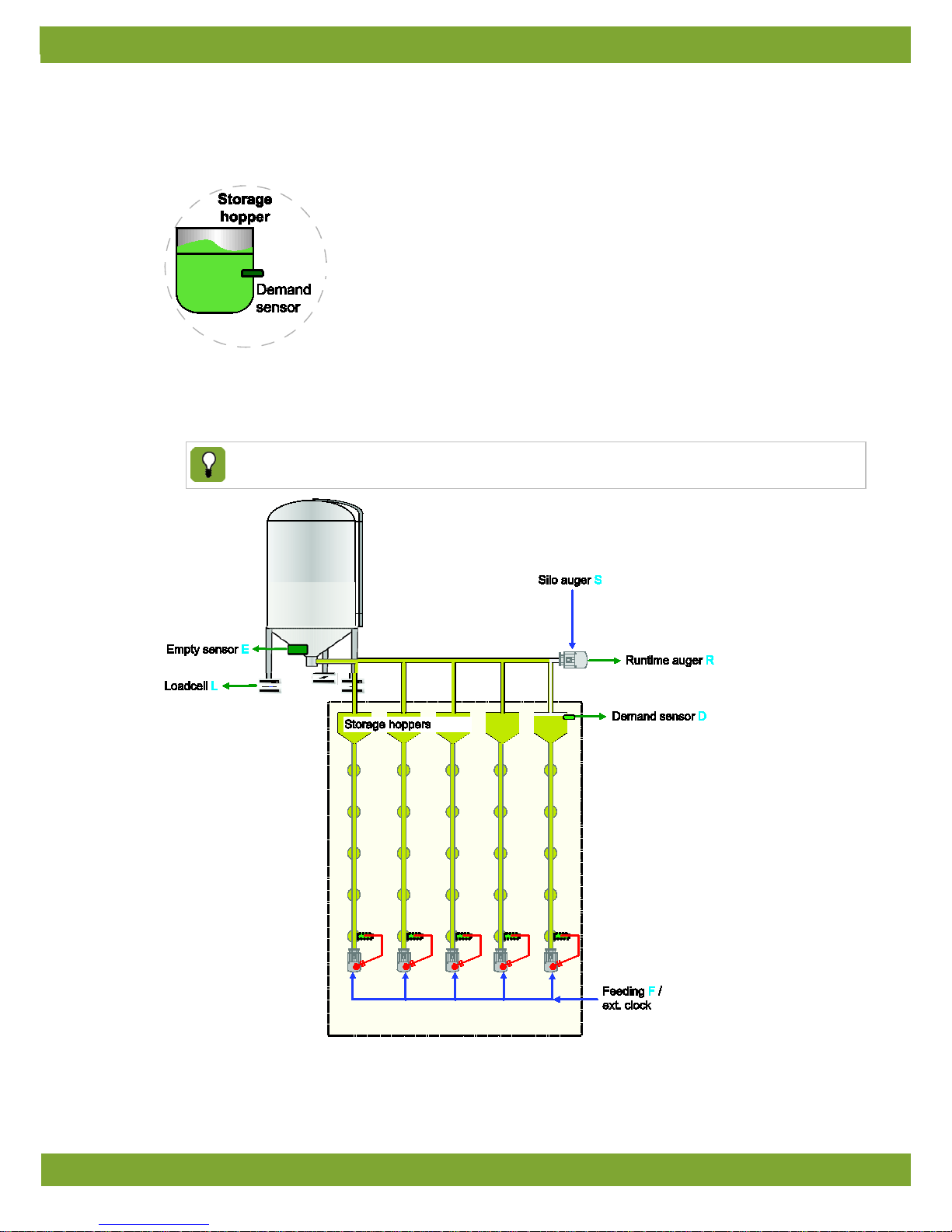
At the start and at the end of each feeding time, the storage hoppers in the house and the transport auger must be
completely filled up. The example below explains the feeding process.
1. The feeding clock will activate the feeding system.
2. The feed level of the house storage hopper will decrease. When this level comes below the demand
sensor(time delayed) it starts a time triggering and after the adjusted time it will ask for feed.
3. The feed transport to the house storage hopper starts and will run unt il the dema nd sen sor i s FULL.
The registration of the feed intake is based on both the capacity of the transport auger and the decrease
of the feed weight in the silo measured by the loadcells.
Page 38
Lumina 40 Appendix: Concept feeding system
34
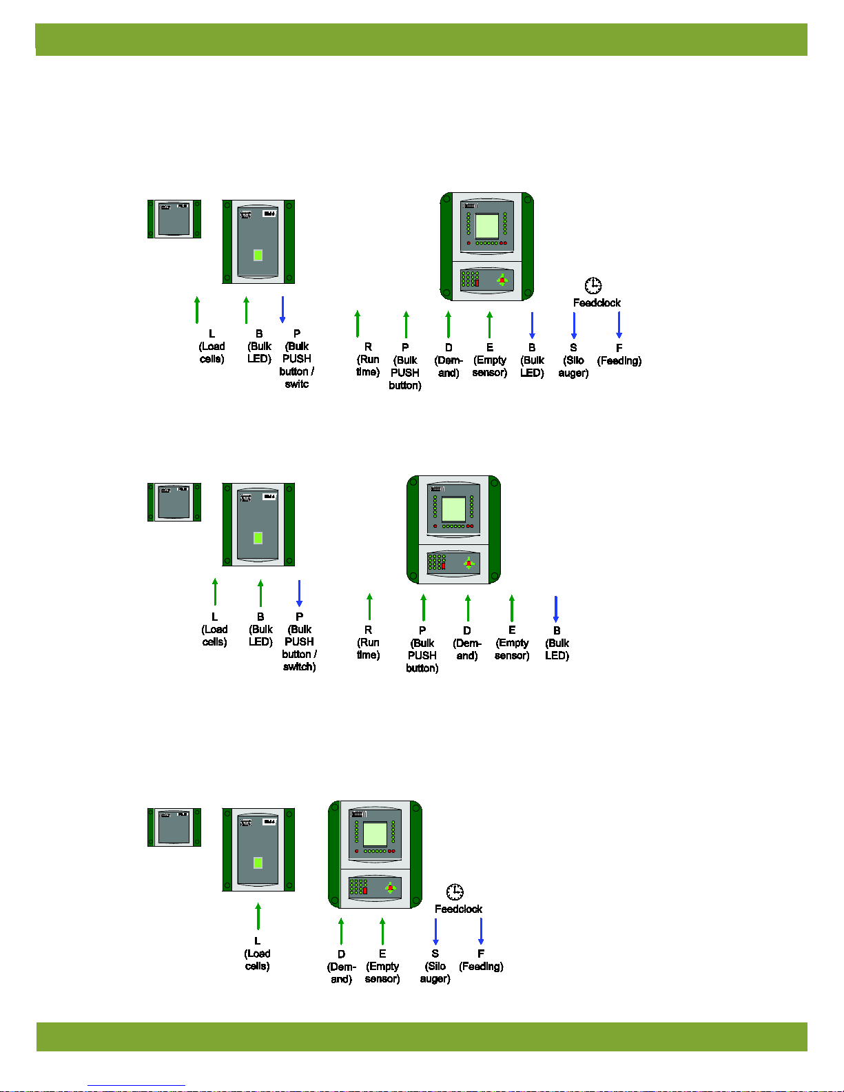
12.1 Bulk feed and dosing at the same time (feeding NOT BLOCKED during filling silo)
12.1.1 Completely controlled
12.1.2 NOT controlled, only registration
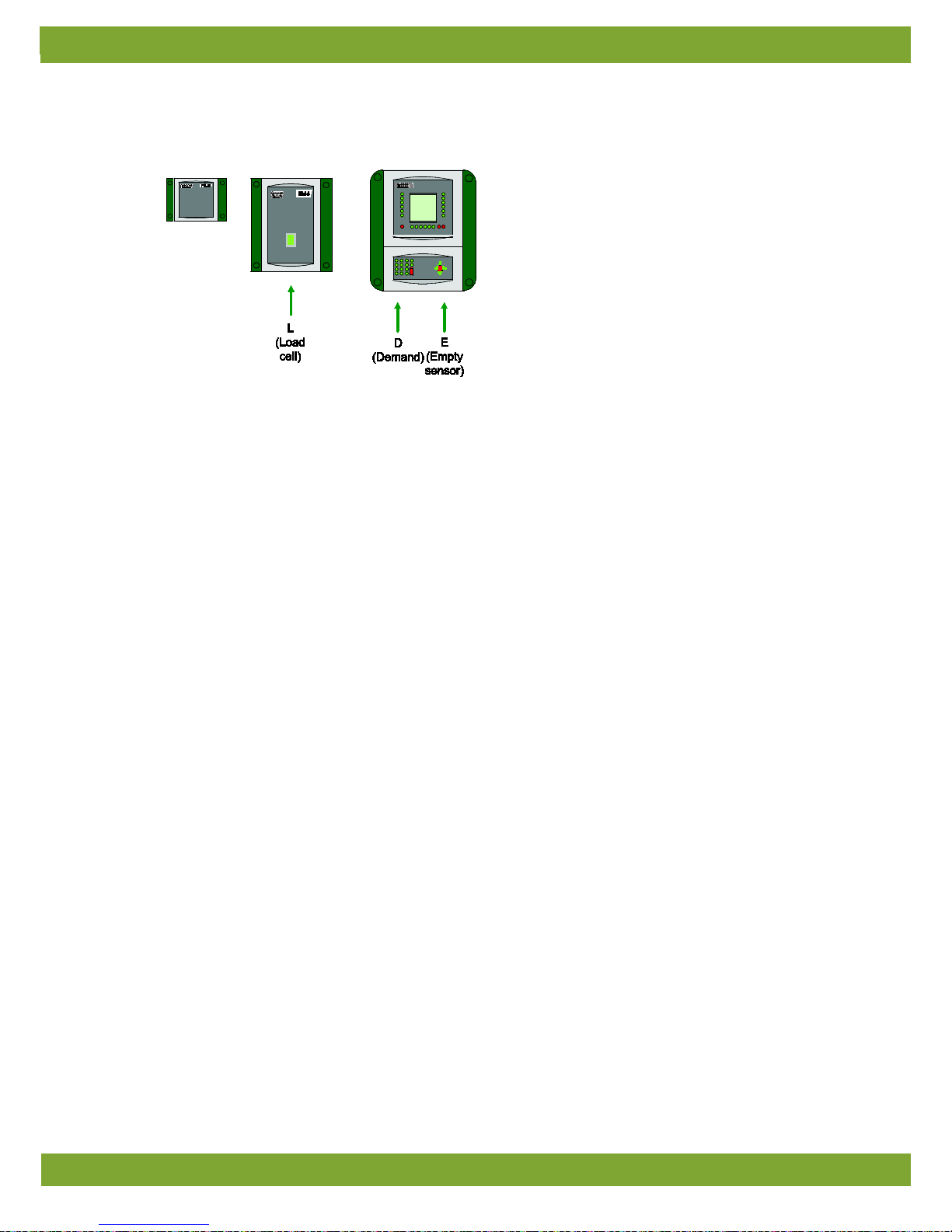
12.2 Bulk feed after stopping the feeding process (feeding BLOCKED during filling silo)
12.2.1 Completely controlled
Page 39
Lumina 40 Appendix: Concept feeding system
35
12.2.2 NOT controlled, only registration
Page 40
Lumina 40 Appendix: EG-declaration of c ompl ian ce
36
13. Appendix: EG-declaration of compliance
Manufacturer Fancom B.V.
Address: Industrieterrein 34
Place: Panningen (the Netherlands)
Hereby declares that:
Lumina 40
Satisfies the conditions of:
1. The Low Voltage Directive 2006/95/EC according to EN-61010
2. the EMC Guideline, directive 2004/108/EC
Emission and immunity according to NEN-EN-IEC 61326
Panningen Date: 15-7-2013
Paul Smits
Managing Director
 Loading...