

Nitek VR448UTP User Manual
Model VR448UTP
L
L
Installation and
4-Port PoE Switch with Network Extender
Operation Manual
Introduction
network devices can operate. The VR448UTP Network Extender consists of two units, a 4-port transmitter and a
receiver. Only the transmitter provides PoE to the connected network device. The receiver is installed at the NVR/IP
equipment side and the transmitter at the IP camera side of the installation.
The VR448UTP Network Extender is designed to greatly extend the distances to which IP cameras and other
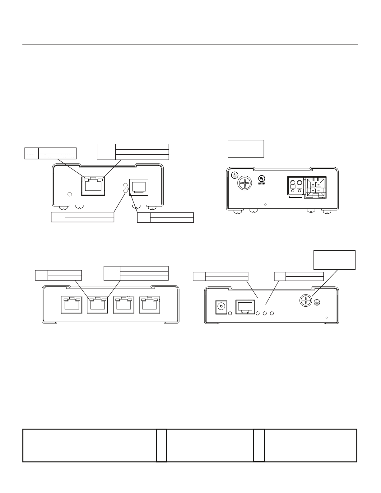
RECEIVER
Speed Off 10 Mbs
Speed Off 10 Mbs
LED Green 100 Mbs
LED Green 100 Mbs
POWER
Status Blinking Establishing Link
LED On Link Established
10/100
Activity Off No Network
Activity Off No Network
LED On Network Detected
ED On Network Detected
Blinking Network Activity
Blinking Network Activity
Data
LINK
Type
Status
ETHERNET
FRONT
WIRE PAIR
Type On Transmitter
LED Off Receiver
Ground
Connection
NITEK
COMMERCIAL
CCTV PRODUCT
40FE
E325724
R
BACK
POWER INPUT
24 AC/DC
12-24 AC/DC, 0-100 Hz
Class 2 only, 1 Amp max.
Activity Off No Network
Speed Off 10 Mbs
Speed Off 10 Mbs
LED Green 100 Mbs
LED Green 100 Mbs
10/100
Data
10/100
Activity Off No Network
LED On Network Detected
ED On Network Detected
Blinking Network Activity
Blinking Network Activity
Data Data
ETHERNET PORTS
FRONT
Note: A sticker on the bottom of each unit identifies whether it is the transmitter or the receiver.
NITEK ®
072110 681200107
TRANSMITTER
Data10/100
10/100
5410 Newport Drive, # 24
Rolling Meadows, IL 60008
Phone: (847) 259-8900
Fax: (847) 259-1300
USA
E-mail: info@nitek.net
WWW.NITEK.NET
Status Blinking Establishing Link
LED On Link Established
POWER INPUT
48 VDC, 1 Amp max.
POWER
UTP
Type On Transmitter
LED Off Receiver
Connected
Type
Speed
LINK STATUS
BACK
De Schans 19-21 2a
8231 KA Lelystad
Tel: +31(0)320-2300005
Fax: +31(0)320-282186
E-mail: info@nitek.nl
WWW.NITEK.NL
EUROPE
Connection
NITEK
Ground
R
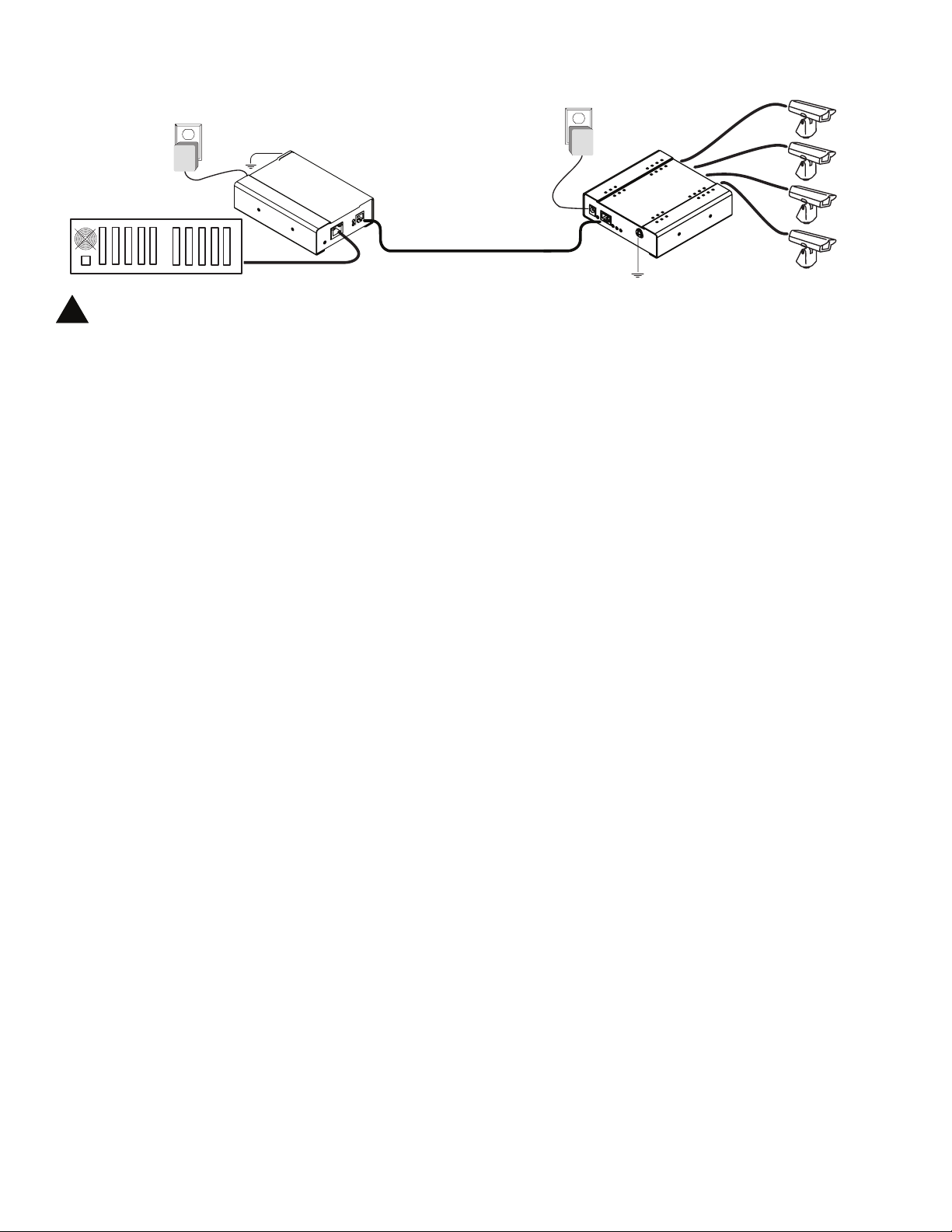
VR448UTP Network Extender Installation Drawing
Powe r
Transformer
Ground
Wire
Powe r
Transformer
NVR
The separate protective earthing terminal provided on this product shall be permanently connected to earth.
!
Network Cable
Install Network to VR448UTP and IP Cameras
1) Connect an earth ground to each unit before making any additional connections.
2) Connect a network cable from the receiver to the security room or IP network equipment.
3) Connect a UTP cable between the transmitter and the receiver. The transmitter uses an RJ45 jack where the center
two pins (4,5) are the output signal. The receiver uses an RJ6 jack where the center two pins (3,4) are the output
signal.
4) Connect a network cable from the transmitter’s four Ethernet jacks to the IP cameras or other network devices.
5) Connect the Class 2 power transformer to the push in power connector of the VR448UTP receiver. The unit
requires 24VAC or VDC @ 1 Amp. There is no polarity to these terminals.
6) Connect the 48VDC 1A power supply to the power connector of the VR448UTP transmitter.
.
Normal Operation
When power is applied to both units the Network LED’s will come on and the link status LED will blink for about 30
seconds as the link is being optimized. When the link is stable the link status LED will remain “ON”. The Ethernet data
LED will blink with network activity.
VR448UTP
VR448UTP
Receiver
Receiver
1 mile (1,600 m)
24AWG or Better
UTP Twisted Pair
Ground
Wire
VR448UTP
Transmitter
w/PoE
Network Cable
IP Cameras
Troubleshooting
After completing installation, if the units are not operating properly, check each step at each unit in order.
1) If the Power LED is off verify the unit’s power connections and verify that the power source is on an active
circuit.
2) If the link status LED does not stop blinking, verify that the UTP cable has been properly installed and make sure
the receiver’s link Type LED is “OFF” and that the transmitter’s link Type LED is “ON”.
3) If the Activity LED is “OFF” verify you have power to the camera and good connections to the RJ45 connectors.
4) If the activity LED is “ON” and the link status LED is “ON” and there is no picture, verify camera IP address and
monitoring IP address are proper and refresh the monitor. Directly attach the camera through a short patch cable
directly to NVR/IP network. Verify that camera and monitor programs are properly functioning.
 Loading...