

Nitek VH856, VH1656, VH856M, VH1656M Installation And Operation Manual

Installation and
Operation Manual
VH856
VH1656
VH856M
VH1656M
NITEK ®
Rev 040810
USA Office: Europe Office (Netherlands):
5410 Newport Drive • Rolling Meadows, IL 60008 De Schans 19-21 2a • 8231 KA Lelystad
Phone: (800) 528-4343 Phone: +31(0) 320-230005
Fax: (847) 259-1300 Fax: +31(0) 320-282186
Email: info@nitek.net Email: info@nitek.nl
Web: www.nitek.net Web: www.nitek.nl
Reduce risk of fire or electrical shock. Do not
expose this product to rain or moisture.
Installation
UTP Video Receiver Hubs are designed to receive standard UTP
video and output standard coax video.
Step 1)
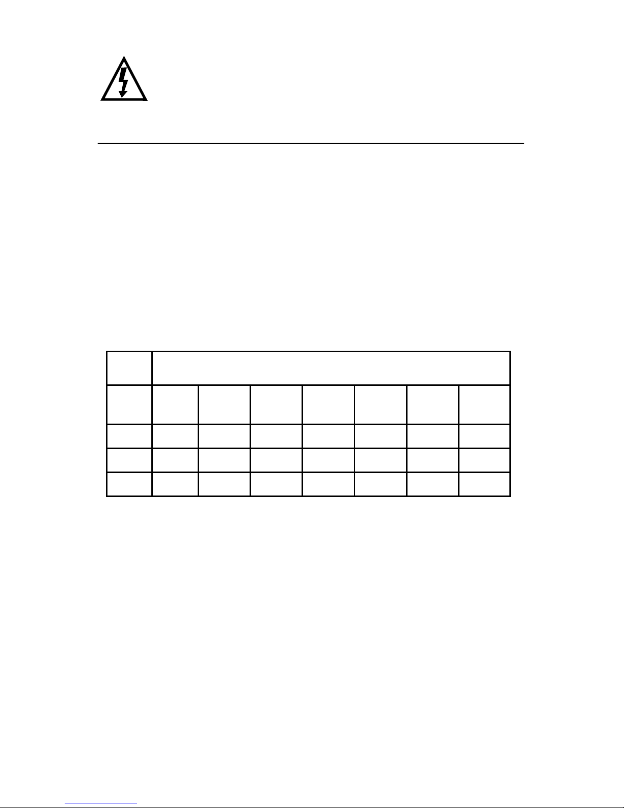
Check the twisted pair for distance and continuity. Do this by
shorting the pair of wires at one end and use an ohm meter to check
the resistance at the other end. The chart below will give you the length
of your wires for a measured loop resistance. Also, use a multimeter to
test the line to make sure there is no voltage on it. Testing each line
and recording the length of each camera run can greatly reduce
installation time. For distances greater than 3,000 feet (900 meters),
longer range units may be needed.
Step 2)
Connect the twisted pair from each transmitter to the input
terminals noting the polarity of the connection. If the wires are reversed
the video will be unviewable on the monitor. Reversing the wires will not
damage the unit.
Step 3)
The receiver hubs are powered from a 12-24 VAC/VDC power
source. In the case of several units a larger central supply may be
used.
Wire
Gage
500
(150)
1000
(300)
2000
(600)
3000
(900)
4000
(1200)
5000
(1500)
6000
(1500)
22 16 32 64 97 129 161 194
24 26 51 103 154 205 257 308
26 41 82 163 245 326 408 490
Distance in Feet (Meters)
 Loading...