

Nitek UTPPTR4 User Manual
Model UTPPTR4
”
”
Primary Surge Protection Panel for Premise Wiring
SPECIFICATION
Installation Manual
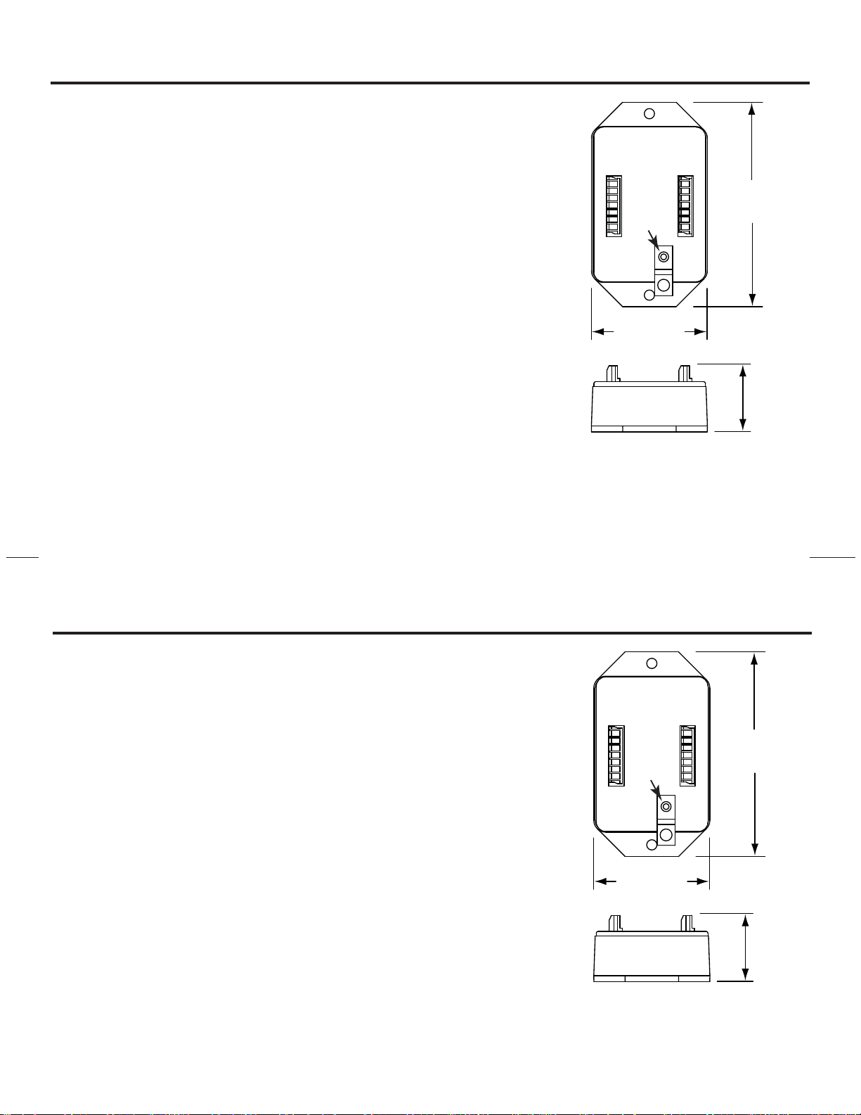
Size 1.7"H x 4.3"W x 2.5"D
(43 H x 109 W x 63 D)
Clamping 15 Volts
Voltage
Impedance 110 ohms
Temperature -40C to +85C
Frequency DC to 10 MHz
INSTALLATION
The UTPPTR4 must be properly installed to insure maximum protection. The
function of the UTPPTR4 is to allow a surge to be routed to ground and to keep protected
equipment inputs to a minimum voltage. The UTPPTR4 should be located as close as
possible to the point were the cable enters the building.
Connect the grounding stud of the UTPPTR4 to a good EARTH GROUND. Finally,
the UNPROTECTED cables should not be crossed or paralleled with the PROTECTED
cables. Crossing cables could provide a path for surge currents to bypass the protection
circuits.
USA Office:
5410 Newport Drive • Rolling Meadows, IL 60008
NITEK
68 024 0103
®
Phone: (800) 528-4343
Fax: (847) 259-1300
E-mail: info@nitek.net • Web: www.nitek.net
PROTECTED
4.3”
EARTH
GROUND
(110)
UNPROTECTED
2.5”
(62)
1.7
(43)
Europe Office:
De Schans 19-21 2a • 8231 KA Lelysted
Netherlands
Phone: +31(0)320 -230005
Fax: +31(0)320 -230005
E-mail: info@nitek.nl • Web: www.nitek.nl
Rev. 031507
Model UTPPTR4
Primary Surge Protection Panel for Premise Wiring
SPECIFICATION
Size 1.7"H x 4.3"W x 2.5"D
(43 H x 109 W x 63 D)
Clamping 15 Volts
Voltage
INSTALLATION
The UTPPTR4 must be properly installed to insure maximum protection. The
function of the UTPPTR4 is to allow a surge to be routed to ground and to keep protected
equipment inputs to a minimum voltage. The UTPPTR4 should be located as close as
possible to the point were the cable enters the building.
Connect the grounding stud of the UTPPTR4 to a good EARTH GROUND. Finally,
the UNPROTECTED cables should not be crossed or paralleled with the PROTECTED
cables. Crossing cables could provide a path for surge currents to bypass the protection
circuits.
Impedance 110 ohms
Temperature -40C to +85C
Frequency DC to 10 MHz
Installation Manual
PROTECTED
4.3”
EARTH
GROUND
UNPROTECTED
2.5”
(62)
(110)
1.7
(43)
NITEK
68 024 0103
USA Office:
5410 Newport Drive • Rolling Meadows, IL 60008
®
Phone: (800) 528-4343
Fax: (847) 259-1300
E-mail: info@nitek.net • Web: www.nitek.net
Europe Office:
De Schans 19-21 2a • 8231 KA Lelysted
Netherlands
Phone: +31(0)320 -230005
Fax: +31(0)320 -230005
E-mail: info@nitek.nl • Web: www.nitek.nl
Rev. 031507
 Loading...