

Nitek TS515x4 User Manual
Model TR515x4
Modular Active Video Receiver Card
Installation and
Operation Manual
Model TS515x4
Modular Active Video Receiver Card
w/Transmitters
Note: This installation should be made by a
qualified service person and conform with local
codes.
Reduce risk of fire or electrical shock. Do not
expose this product to rain or moisture.
!
Introduction
Twisted Sender has been designed by Nitek to transmit video signals over a point to point pair of wires. The wire
should be free of voltage or other outside signals. Twisted Sender can turn your in-house phone lines, leased
telephone lines or cable runs into pathways for video signals. Twisted Sender is ideal for shopping malls, parking
garages, remote gates, large factories, airports or any number of places where you need to connect video
equipment.
System Specifications
TR515x4 includes the following: TS515x4 System includes the following:
(1) TR515x4 Receiver Card (1) TR515x4 Receiver Card
(4) VB37F Transmitters
Receiver Unit Transmitter Unit
Size 1 card slot Size 1.3”H x 2.0”W x .95”D
Power Requirements Power supplied by Card Cage Power Requirements None
Input (4) Low voltage current loop Input-Video 1 vpp composite video
from transmitter unit Monochrome or Color
Output-Video (1) 1.0 vpp composite video
Monochrome or Color
Installation
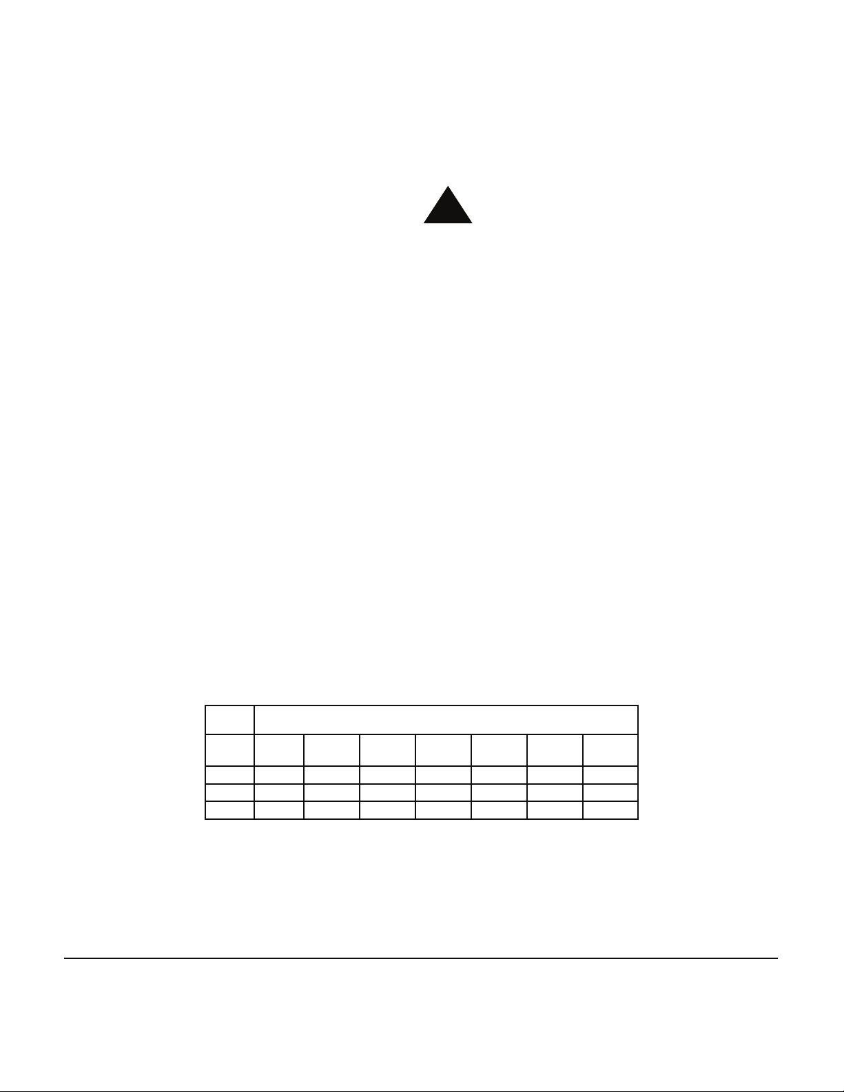
1) Check the twisted pair for continuity. Do this by shorting the pair of wires at one end and using an ohm
meter to check the resistance at the other end. The chart below will give you the length of your wires for a
measured resistance. Use a multimeter to make sure there is no voltage on the line.
For distances greater than 1,500 feet, there are several other systems available. Contact your local
Distributor or Nitek Technical Department for assistance.
Wire
Gage
300
(90)
22 10 6 32 48 64 80 96
24 15 25 51 76 102 127 153
26 25 41 82 123 164 205 246
The TR515x4 receiver can be used with any standard twisted pair video camera or Balun type transceiver device.
Steps 2 and 3 refer to the Nitek VB37 Balun.
Distance in Feet (Meters)
500
(150)
1000
(300)
1500
(450)
2000
(600)
2500
(750)
3000
(900)
NITEK®
USA Office:
5410 Newport Drive, Rolling Meadows, IL 60008
Phone: (800) 528-4343
Fax: (847) 259-1300
E-mail: info@nitek.net
WWW.NITEK.NET
685150102
Europe Office:
De Schans 19-21 2a, 8231 KA Lelystad
The Netherlands
Tel: +31(0)320-2300005
Fax: +31(0)320-282186
E-mail: info@nitek.nl
WWW.NITEK.NL
Rev 030111
Installation (cont’d)
2) Check the video input at the transmitter unit to make sure you have video present. Connect the
video to the BNC jack of the VB37 transmitter unit. The transmitter is a passive device called a
Balun and requires no power.
3) Connect the twisted pair to the screw terminals and note the polarity of this connection. If the
wires are reversed, when you connect the receiver the video will not be viewable on the monitor.
4) Plug the receiver card into the Nitek card cage and connect a test monitor to the desired output
BNC connector (1, 2, 3 or 4).
5) Locate the twisted pair input terminals (marked “+” and “-”) which match the video output BNC
selected. Connect the twisted pair, note the polarity of the connection. If the wires are reversed the
video will not be viewable, this will not damage the unit. Reverse the wires and the video will be
correct.
6) DIP switches are provided so that the unit can be adjusted for the best picture. The following
settings are factory recommended for normal conditions. For added sharpness adjust switches 7
and 8. For more gain adjust switches 5 and 6. Switches 1, 2 and 3, 4 must be operated in pairs.
Unmarked Positions are Off Video
Distance
100-400ft
(30-120m)
400-700ft
(120-200m)
700-900ft
(200-275m)
900-1100ft
(275-330m)
1100-1300ft
(330-400m)
>1300ft
(>400m)
1 2 3 4 5 6 7 8
ON
ON ON ON
ON ON ON
ON ON ON ON
ON ON ON ON ON
Switch Position
Level Gain
Video
Peaking
7) You can now disconnect the test monitor and connect the video out of the receiver unit as
needed for your installation.
Troubleshooting
Problem Video inverted or rolling and unstable.
Fix/Cause • Reverse the wires of the twisted pair at either the transmitter or receiver.
Problem No video out at the receiver.
Fix/Cause • Check to make sure that there is video in at the transmit end.
• Make sure that the pair of wires you are using is not open or shorted between the
transmit and receive points.
Problem Ghost image at the receiver.
Fix/Cause • Bridge tap or “T” tap on the twisted pair video line. Remove tap.
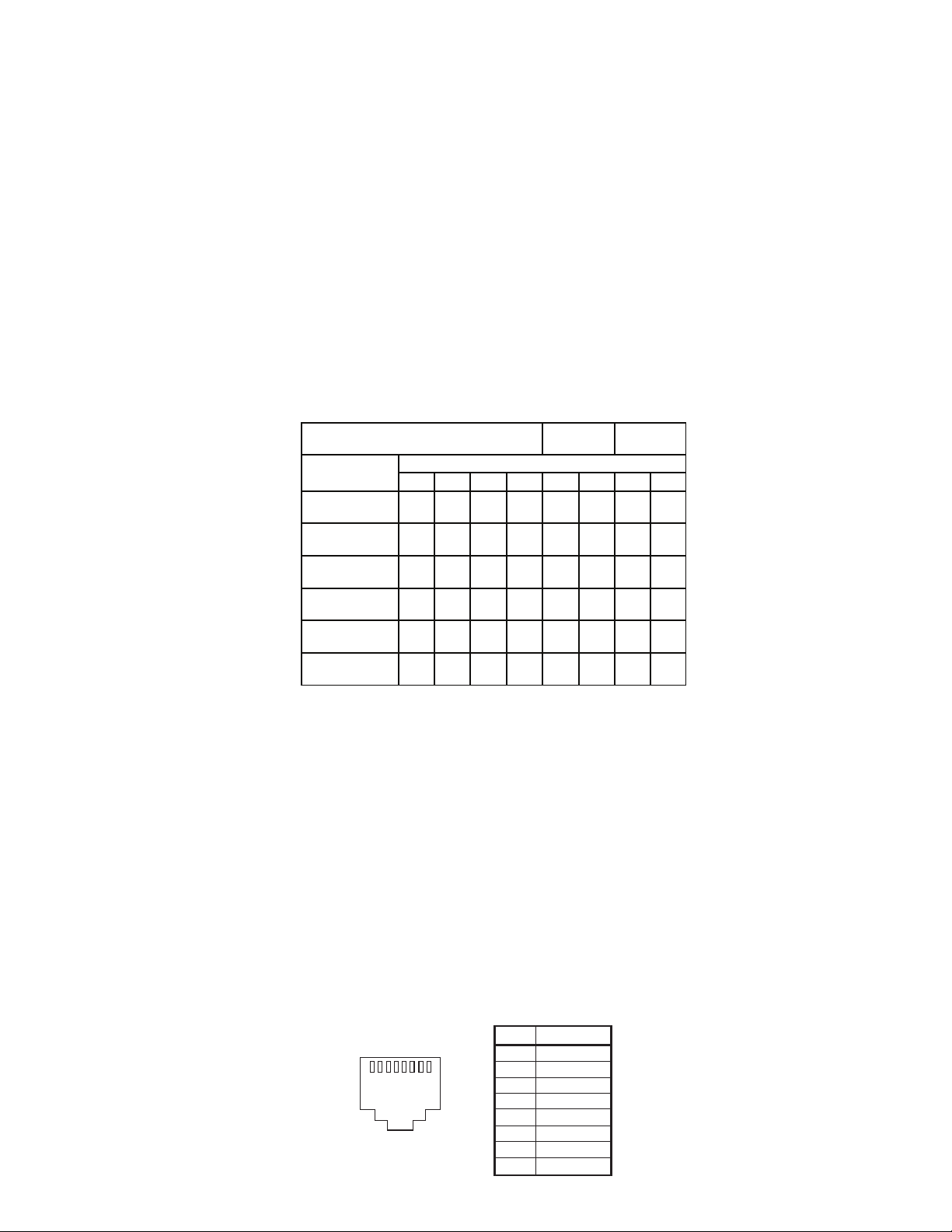
Twisted Pair Wiring
for T568B Jack
2 2 3 1 1 3 4 4
+
-
+ - + - +
-
1 2 3 4 5 6 7 8
T568B
Pin# Wire
1 Video 2 +
2 Video 2
3 Video 3 +
4 Video 1
5 Video 1 +
6 Video 3
7 Video 4 +
8 Video 4
-
-
-
-
 Loading...