

Nitek TR515x8 User Manual
Installation Instructions
TR515x8 Card
Note: This installation should be made by a qualified
service person and conform with local codes.
NITEK
5410 Newport Drive, Suite 24
Rolling Meadows, IL 60008
®
PHONE (847) 259-8900
Reduce risk of fire or electrical shock. Do
not expose this product to rain or moisture.
FAX (847) 259-1300
Internet: www.nitek.net
Specifications
Power Requirements: Power is supplied by VH3200
UTP Wire Length: up to 1500 feet with passive transmitter
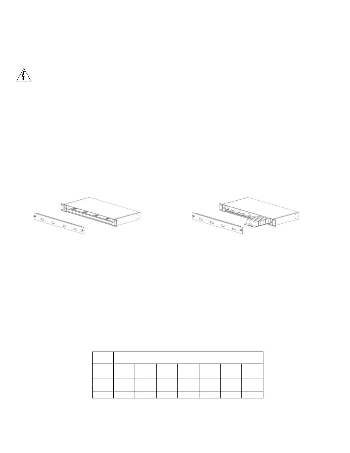
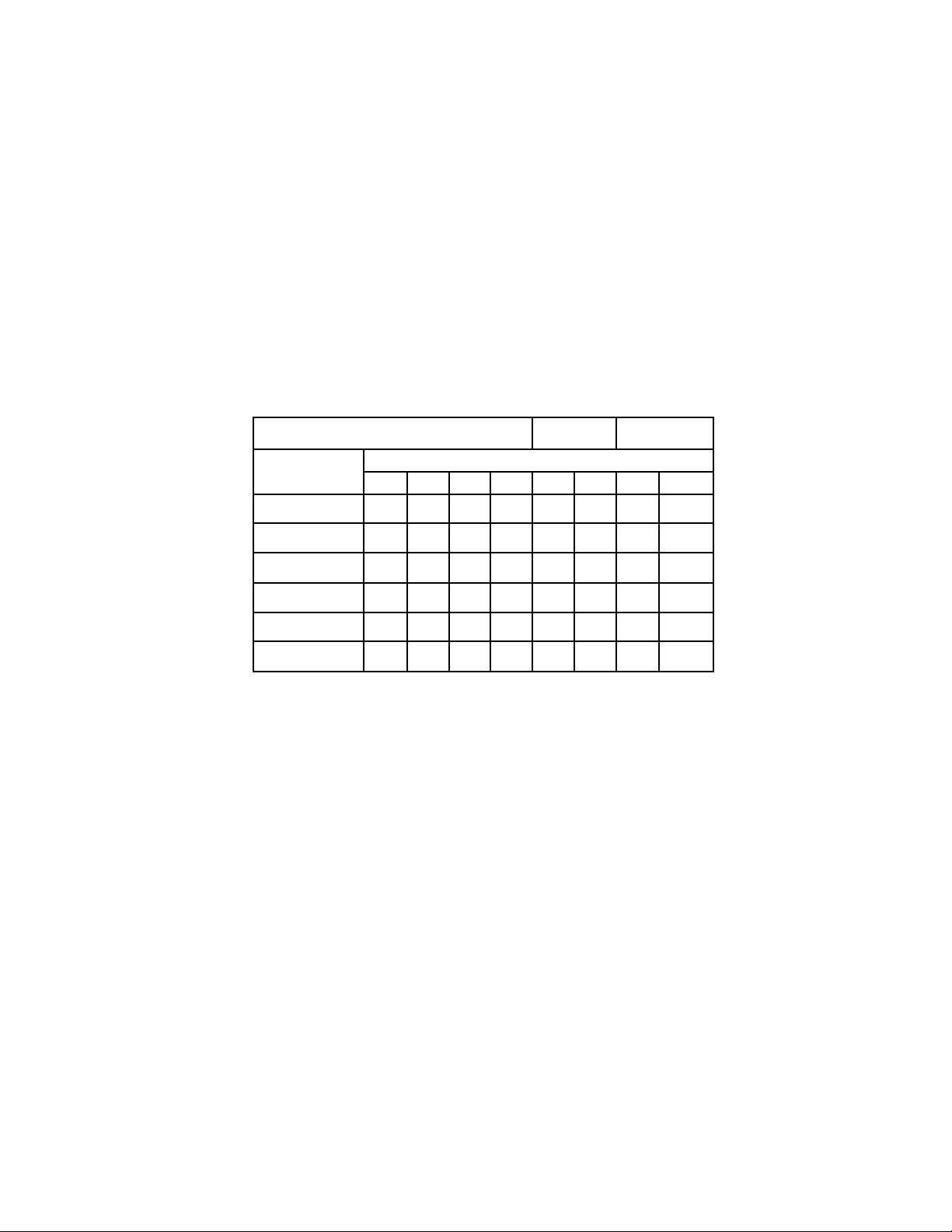
To install the TR515x8, remove the front panel of the VH3200 Modular Hub by pulling on the two front
panel knobs. Insert the card into any open slot. Replace the front cover and press the knob in to lock it
in place.
Remove front panel Install cards
Determining Cable Length
Check the twisted pair for continuity. Do this by shorting the pair of wires at one end and use an ohm meter to check
the resistance at the other end. Use the chart below to determine the length of your wires for a measured
resistance. Also, use the multimeter to test the line and make sure there is no voltage on it. Testing each line and
recording the length for each camera run can greatly reduce installation time. For distances greater than 1,500 feet
different receiver units are recommended, contact NITEK for specific model numbers.
ERIW
EGAG
005
)251(
2261234679921161491
426215301451502752803
621428361542623804094
000,1
)403(
000,2
)016(
000,3
)419(
)SRETEM(TEEFNIECNATSID
000,4
)9121(
000,5
)4251(
000,6
)9281(
Rev 102403
TR515x8 Card w/Passive (Balun) Transmitter
1. Connect Balun to camera - Using the installation manual provided with the balun, connect it to the video source,
usually a video camera. If you have a UTP ready camera connect the twisted pair directly to the camera video out.
2. Connect twisted pair to VH3200 - The twisted pair connects to the terminal blocks on the rear of the VH3200.
3. Connect video out to your system - Using standard coax cable, connect from the video out BNC to your
system as needed for viewing.
4. Set DIP switch for distance - Using the chart below set the 8 position DIP switch on the TR515x8 for the
distance of your twisted pair line plus any coax on each end. The modules are numbered to match the connections.
Do not just try settings to see what works. Knowing the distance and setting the switch will save you time and
provide you with the best possible picture. Note that the settings listed are for standard communication cable.
Should you be using wire gages less than 22 awg or shielded wire with less than 10 pair your setting may vary,
call Nitek Tech Support for help.
ffOerasnoitisoPdekramnU
ecnatsiD
1234567 8
.tf004-001<
)m121-03(
.tf007-004
)m312-121(
.tf009-007
)m472-312(
.tf001,1-009
)m533-472(
.tf003,1-001,1
)m693-533(
.tf003,1>
)m693(
NONONONONO
NONONO
NONONO
NONONONO
oediV
niaGleveL
noitisoPhctiwS
NO
oediV
gnikaeP
 Loading...