

Nitek PV824 User Manual
Balun with
Power, Video and Data
DVR
Coaxial
Cables
4-pair
Category Cables
Control Room / MDF
Video
Fixed Cameras
PV824 Panel
Data
Model PV824Model PV824
Model PV824
Model PV824Model PV824
POWER and VIDEO DISTRIBUTOR FOR UTP and STP CATEGORY CABLES
Note: This installation should be made by a qualified service person and conform with local codes.
Reduce risk of fire or electrical shock. Do not
expose this product to rain or moisture.
Installation and
Operation Manual
Specifications
10.6
Power Input: 115VAC 50/60 Hz, 1 Amp
Power Output:
Size:
10.6
4.0
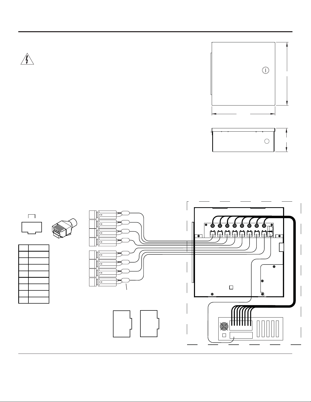
Typical Installation
The PV824 is designed using RJ45 connectors. Cable terminations are 568B. The diagram below shows
a common installation and the hook ups for each connector. Pin assignments are shown in the table below.
3
2 1 4
+
-+-+-+-
12345678
STANDARD 568B
WIRING
PIN Color Code
1WHT/ORG
2 ORG/WHT
3WHT/GRN
4BLU/WHT
5WHT/BLU
6 GRN/WHT
7 WHT/ BRN
8 BRN/WHT
8
1
CAMERA PORTS
+
8
Powe r
-
7
Powe r
+
6
Powe r
+ Data
5
-
Data
4
-
3
Powe r
-
2
Video
+
1
Video
DATA PORTS
-
8
Data 4
+
7
Data 4
-
6
Data 3
+ Data 1
5
-
Data 1
4
+
3
Data 3
-
2
Data 2
+
1
Data 2
USA Office:
5410 Newport Drive • Rolling Meadows, IL 60008
Phone: (800) 528-4343
Fax: (847) 259-1300
E-mail: info@nitek.net • Web: www.nitek.net
688240101 Rev. 111607
NITEK
®
Europe Office:
De Schans 19-21 2a • 8231 KA Lelysted
Netherlands
Phone: +31(0)320 -230005
Fax: +31(0)320 -282186
E-mail: info@nitek.nl • Web: www.nitek.nl

INSTALLATION
Connecting the PV824 Base Unit
1. Mount the unit in a secure location keeping in mind that your primary power must be routed in through one
of the knockouts in the lower right corner. Remove the protective cover for the primary wiring. Make the
needed primary wiring hook ups and replace the protective cover. Do not power up the unit until all needed
connections are made.
2. Connect wires leading to cameras using 568B wiring. A table of the connections and a 568B wiring chart are
shown on the previous page.
3. Connect a RG59 coaxial cable from the BNC jack to your DVR or other viewing device.
4. A data connection is provided for each camera port. The data path is a straight through connection for each
camera run and may be used for any number of signal types including PTZ control, audio, contact closure,
etc.
5. Power up the PV824 base unit. A red power LED is provided for each camera. When video is present a green
LED will light for the particular port. The green LED indicates video is returning from the camera.
Connecting the Video, Power and Data at the Camera End
1. The PV824 supports a video, power and data connection. These wire pairs can be independently connected
to a UTP ready video camera or to a Nitek balun with power, video and data connections.
2. Power to the PV824 base unit should be off when making camera connections. Connection should be wired
for 568B. A chart of connections and 568B wiring is provided on the previous page.
Troubleshooting
NO POWER LED - A red power LED is provided for each camera. If the power LED is not on for a particular
port, reset the power to the PV824. If the power LED remains off remove the camera connection from that
port and reset power to the PV824. With no load on the port the LED should light, this would indicate a
problem with the camera wire run or the camera itself.
NO VIDEO LED - A green LED is provided to indicate that video is being received at the PV824 unit. If the
video LED is off but the power LED is on then there could be a problem with the camera or the video wiring.
Try moving a working camera to the port in question to confirm that the port is working correctly.
 Loading...