

Nitek PS115 User Manual
Installation Instructions
19.0
8.6
1.75
PS115 Power Supply
Note: This installation should be made by a qualified
service person and conform with local codes.
Reduce risk of fire or electrical shock do
!
not expose this product to rain or moisture.
WARNING
CAUTION: To reduce the risk of electric shock do not remove cover. No user-serviceable
parts inside. Refer servicing to qualified service personnel.
NITEK ®
5410 Newport Drive, Suite 24
Rolling Meadows, IL 60008
PHONE (847) 259-8900
FAX (847) 259-1300
WWW.NITEK.NET
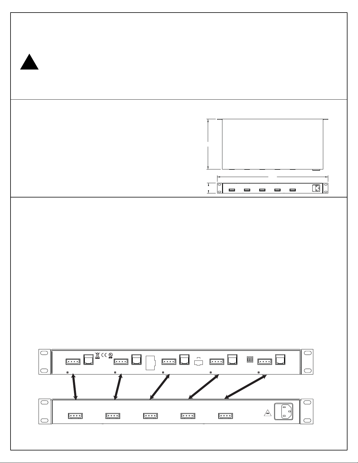
Specifications
PS115 Dimensional Diagram
Size 1.75” H x 19.0” W x 8.6” D
Power Requirements 120 VAC
Output Voltage 24 and 28 VAC
Output Current 12 Amps
Enclosure Type Standard 19” rack,
1 RU in height
Installation (PS115 and CX452)
The PS115 has five easy connect jacks for outputting power and is designed for use with
several different products, this section is for use with the CX452. Each of the PS115 power
output ports can supply up to 80 watts of power. Connect the PS115 power outputs to the
CX452, as shown in the diagram below, using the supplied jumper cables.
Care should be taken not to overload the PS115 outputs but if an overload does occur, the
outputs are individually protected from over current by an auto-resetting fuse. To reset a
PS115 output remove the problem power connector from the CX452. After fixing any over load
conditions, reconnect the power connector.
Refer to the CX452 instruction manual for details on the CX452 and the optional cards it uses.
013012
24-29VAC
50/60 Hz
3 amp max.
Class 2 only
CLASS 2
POWER OUTPUT
24-29VAC 50/60 Hz
3 Amp Max.
COMMERCIAL
CCTV PRODUCT
E240043
Class 2 only
CLASS 2
POWER OUTPUT
24-29VAC 50/60 Hz
3 Amp Max.
CX452 common hookup diagram
CX452
21UP
24-29VAC
50/60 Hz
3 amp max.
VIDEO PORTS
-
8
Vid 4
+
7
Vid 4
-
6
Vid 3
+ Vid 1
5
-
Vid 1
4
+
3
Video PortVideo Port
Vid 3
-
2
Vid 2
+
1
Vid 2
CLASS 2
POWER OUTPUT
24-29VAC 50/60 Hz
3 Amp Max.
24-29VAC
50/60 Hz
3 amp max.
Class 2 only
Video Port
24-29VAC 50/60 Hz
CLASS 2
POWER OUTPUT
3 Amp Max.
2 1 4
-+-+-+-
+
12345678
T568B
3
24-29VAC
50/60 Hz
3 amp max.
Class 2 only
PS115
Video Port
CLASS 2
POWER OUTPUT
24-29VAC 50/60 Hz
3 Amp Max.
+
Control Data
-
24-29VAC
50/60 Hz
3 amp max.
Class 2 only
120 VAC
50/60Hz
5 Amps
CAUTION
RISK OF FIRE REPLACE FUSE
AS MARKED
Video Port
5 A 250V
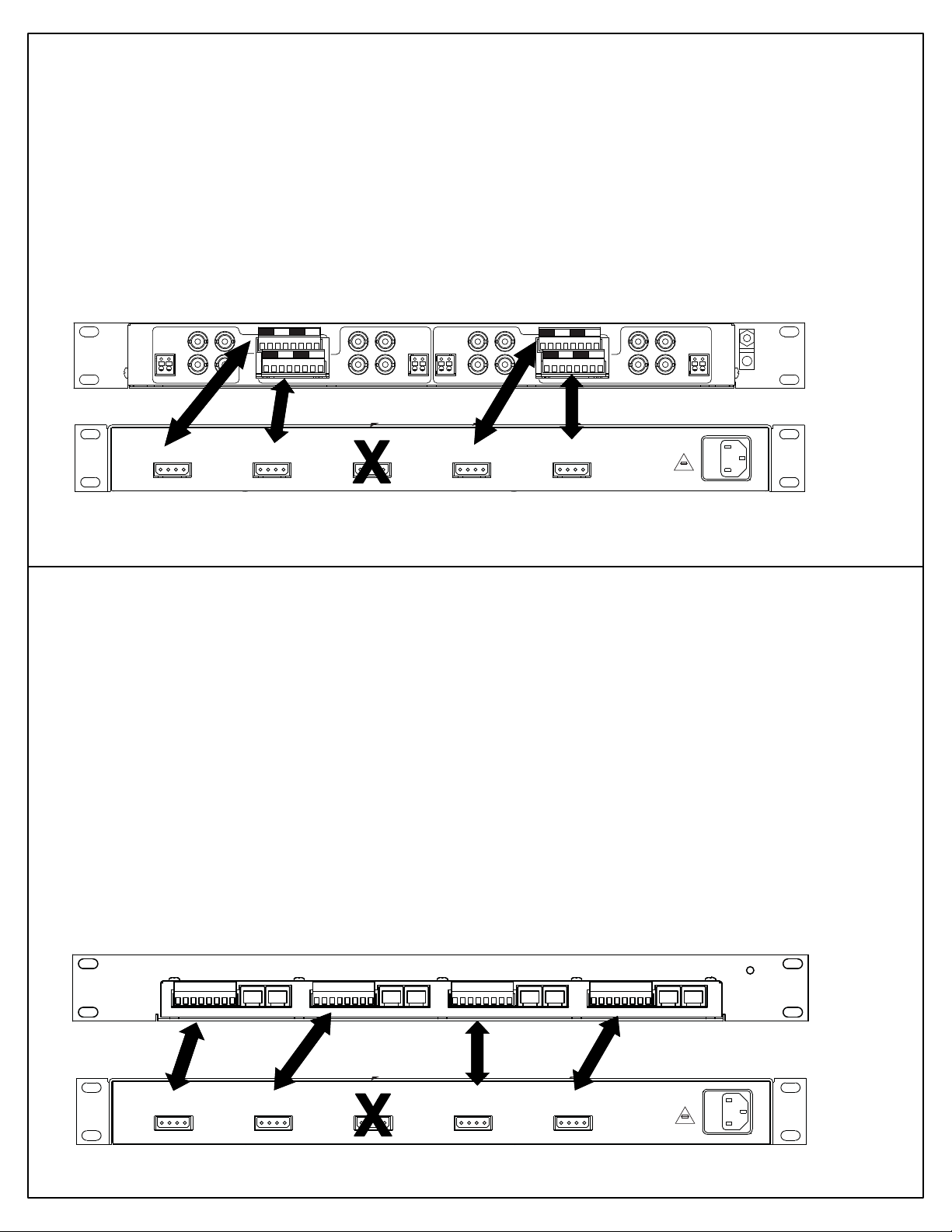
Installation (PS115 and PVR164)
19.0
5.0
1.710
1
2
3
4
DATA IN
D
C
B
A
+
-
DATA IN
DATA IN
DATA IN
+
-
+
-
+
-
1
2
3
4
1
2
3
4
1
2
3
4
The PS115 has five easy connect jacks for outputting power and is designed for use with several
different products, this section is for use w ith the PVR164. Each o f the PS115 power outpu t ports can supply up
to 80 watts of power. Connect the PS115 power outputs to the PVR164, as shown in the diagram below, using
the supplied jumper cables. Note that the center connector is left unused.
Care should be taken not to overload the PS115 outputs but if an overload does occur, the outputs are
individually protected from over current by an auto-resetting fuse. To reset a PS115 output remove the problem
power connector from the PVR164. After fixing any over load conditions, reconnect the power connec tor.
Refer to the PVR164 instruct ion manual for details on the additional connections.
PVR164 common hookup diagram
13
DATA IN
CLASS 2
POWER OUTPUT
24-29VAC 50/60 Hz
3 Amp Max.
24
+-+
+
13
+-+
+
CLASS 2
POWER OUTPUT
24-29VAC 50/60 Hz
3 Amp Max.
-+-
-
24
-+-
-
CLASS 2
POWER OUTPUT
24-29VAC 50/60 Hz
3 Amp Max.
DATA IN
DATA IN
PVR164
POWER OUTPUT
24-29VAC 50/60 Hz
3 Amp Max.
CLASS 2
13
24
-+-
+-+
-
+
13
24
-+-
+-+
-
+
CLASS 2
POWER OUTPUT
24-29VAC 50/60 Hz
3 Amp Max.
120 VAC
50/60Hz
5 Amps
5 A 250V
CAUTION
RISK OF FIRE REPLACE FUSE
AS MARKED
DATA IN
PS115
Installation (PS115 and PVX164)
The PS115 has five easy connect jacks for outputting power and is designed for use with
several different products, this section is for use with the PVX164. Each of the PS115 power
output ports can supply up to 80 watts of power. Connect the PS115 power outputs to the
PVR164, as shown in the diagram below, using the supplied jumper cables. Note that the
center connector is left unused.
Care should be taken not to overload the PS115 outputs but if an overload does occur, the
outputs are individually protected from over current by an auto-resetting fuse. To reset a
PS115 output remove the problem power connector from the PVX164. After fixing any over
load conditions, reconnect the power connector.
Refer to the PVR164 instruction manual for details on the additional connections.
PVX164 common hookup diagram
PVX164
POWER
24
1
+
+ -+
-
1 - 4
3
+
-
1 - 4
VIDEO
DATA
-
POWER
68
5
+
+ -+
-
5 - 8
7
+
-
5 - 8
VIDEO
DATA
-
9
+
-
POWER
10 12
11
+
+ -+
-
9 - 12
9 - 12
VIDEO
DATA
-
13
+
-
POWER
14 16
15
+
+ -+
-
13 - 16
13 - 16
VIDEO
DATA
-
120 VAC
50/60Hz
5 Amps
5 A 250V
CAUTION
RISK OF FIRE REPLACE FUSE
AS MARKED
CLASS 2
POWER OUTPUT
24-29VAC 50/60 Hz
3 Amp Max.
PS115
CLASS 2
POWER OUTPUT
24-29VAC 50/60 Hz
3 Amp Max.
CLASS 2
POWER OUTPUT
24-29VAC 50/60 Hz
3 Amp Max.
CLASS 2
POWER OUTPUT
24-29VAC 50/60 Hz
3 Amp Max.
CLASS 2
POWER OUTPUT
24-29VAC 50/60 Hz
3 Amp Max.
 Loading...