

Nitek MM-100, MM-1000, MM-100-POE, MS-100, MS-1000 Installation And Operation Manual
...
MM-100/1000 & MS-100/1000
10/100/1000 MEDIA CONVERTERS w/PoE Option
Introducon
This manual applies to the following media converters.
MM-100: Mul-Mode SC, 10/100 Mbps MS-100: Single-Mode SC, 10/100 Mbps
MM-1000: Mul-Mode SC, 10/100/1000 Mbps MS-1000: Single-Mode SC, 10/100/1000 Mbps
MM-100-POE: Mul-Mode SC, 10/100 Mbps, 30W PoE MS-100-POE: Single-Mode SC, 10/100 Mbps, 30W PoE
NITEK ®
De Aar 99
8253 PN Dronten
The Netherlands
Tel: +31(0) 321 310 043
E-mail: info@nitekeurope.net
WWW.NITEK.NET
USA
5410 Newport Drive, # 24
Rolling Meadows, IL 60008
Phone: (847) 259-8900
Fax: (847) 259-1300
E-mail: info@nitek.net
WWW.NITEK.NET
EUROPE
20171128
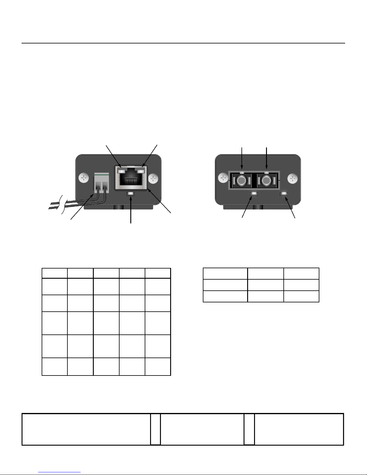
RJ45 Side
Opcal Side
680700106
TX RX
PoE LED
(on POE Models)
Opcal
Link LED
Device
Power LED
Power
Jack
RJ45
Jack
1000 Mbps
Link LED
10/100 Mbps
Link LED
LED OFF GREEN ORANGE BLINK
DEVICE
POWER
NO
POWER
POWER N/A N/A
OPTICAL
LINK
NO
LINK
LINKED N/A N/A
10/100
Mbps
LINK
NO
LINK
100
Mbps
LINK
10
Mbps
LINK
ACTIVE
LINK
1000
Mbps
LINK
NO
LINK
1000
Mbps
LINK
N/A
ACTIVE
LINK
PoE
PoE
OFF
PoE
ON
N/A
PoE
FAULT
MODELS DC INPUT* AC INPUT
Non-PoE 6-16V 6-12V
PoE 48-56V N/A
LED FUNCTIONS POWER JACK OPTIONS
*POLARITY NOT IMPORTANT DUE TO INTERNAL BRIDGE
Installation and
Operation Manual
Installation and
Operation Manual
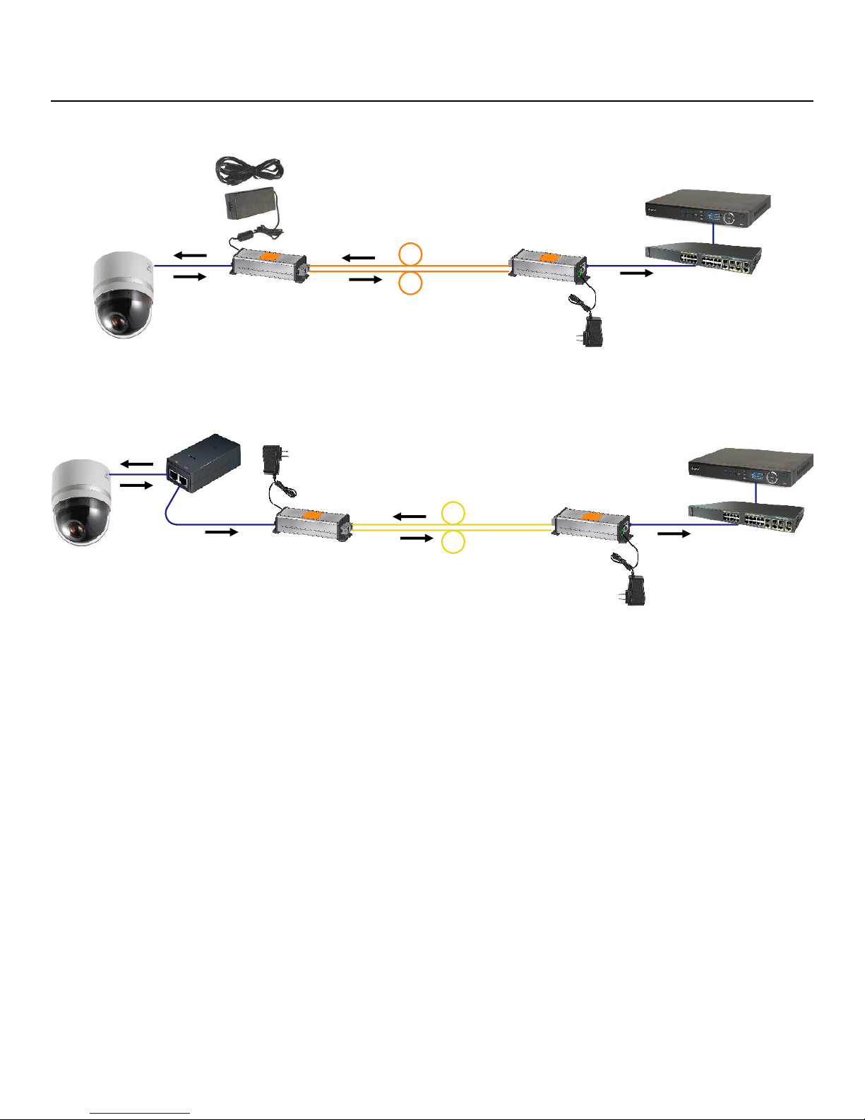
PoE Media Converter Installaon
Installing the MM-100/1000 & MS-100/1000 Series Media Converters
Refer to the diagrams above when installing. Use best industry pracces and follow all local building codes.
1. Connect the provided AC adapter to the power jack of the local unit and confirm that its device power LED turns on.
2. Connect a network cable from the network equipment to the RJ45 jack of the local unit and confirm that a link LED on its RJ45
jack turns on.
3. Connect appropriate optical cables (see note below) to the TX and RX ports of the local unit.
4. Connect the provided AC adapter or PoE power supply to the power jack of the remote unit and confirm that the device power
LED turns on.
5. Connect the other ends of the optical cables from step 4 to the TX and RX ports of the remote unit.
6. If the remote optical link LED doesn’t light, swap the cables between the TX and RX ports and confirm that it lights.
7. If the remote device will be powered by its own supply, connect that power supply as specified by its documentation and skip
to step 10.
8. If the remote media converter is a non-PoE model and PoE is required:
A. Connect the RJ45 jack of the remote media converter to the Data In jack of the PoE injector.
B. Connect the PoE & Data Out jack of the PoE injector to the remote device and skip to step 10.
9. If the remote media converter will provide PoE, connect the RJ45 jack of the remote unit to the remote device and conrm
that the PoE LED lights.
10. Confirm that the remote device is powered and that a link LED on the RJ45 jack of the remote unit turns on.
11. If the remote device is active, confirm that a link LED is blinking on the RJ45 jack of the remote unit.
12. Confirm that the optical link LED lights on the local unit and verify data connectivity via the network equipment.
NOTE:
MM models require multi-mode SC-terminated fiber cables, which are orange.
MS models require single-mode SC-terminated fiber cables, which are yellow.
Remote TX to Local RX
Remote Unit
w/PoE
Local Unit
Non-PoE Media Converter Installaon
Remote RX to Local TX
Remote TX to Local RX
Remote Unit
w/o PoE
Local Unit
Remote RX to Local TX
PoE Power
Supply
PoE
Injector
AC Adapter
AC Adapter
AC Adapter
Remote
Device
Remote
Device
Network
Equipment
Network
Equipment
MM-100/1000 & MS-100/1000
10/100/1000 MEDIA CONVERTERS w/PoE Option
Data
Data
Data
Data
PoE
Data
Data
PoE
Data
Data
Data
 Loading...