

Nitek FSS20811S User Manual

Models FSS21611S & FSS20811S
16 & 8 Channel Video Optical Systems include either one FRS21611S
Receiver & one FTS21611S Transmitter or one FRS20811S Receiver &
one FTS20811S Transmitter
Reduce risk of fire or electrical shock. Do not
expose this product to rain or moisture.
Note: This installation should be made by a qualified
service person and conform with local codes.
Introduction
The NITEK FSS21611S (16 Channel) and FSS20811S (8 Channel) fiber transmitter and receiver sets, are a fiber-optic
Universal-Mode™ system which can operate on either single-mode or multi-mode fiber. Digital transmission provides
broadcast quality video performance and bi-directional data, up to distances of 20Km (single-mode) and 1.2Km (multimode). The RS422/RS485 port allows for the use of camera controls, the system begins communicating after power-up.
Safety
The FSS21611S & FSS20811S use a Class 1 laser system in accordance with IEC 60825-1.
It is always advisable to follow good practice when working with optical fiber systems. This includes:
• Do not stare with unprotected eyes at fiber ends or connector faces.
• Use only approved filtered or attenuating viewing devices.
• For other safety issues and advice on good practices associated with optical fiber systems see IEC 60825-1 or your
local safety officer
.
Installation and
Operation Manual
Device Mounting Options
The FSS21611S and FSS20811S can be either rack mounted, or resting on a desktop.
NOTES:
1. Use all four mounting screws to properly secure the unit to the rack.
2. Mechanical loading - The mounting ears were designed for two ears to support one unit.
3. Cable space - Allow for proper bend radius of the fiber cable exiting the back of the unit. Do not exceed the recom-
mended minimum bend radius of fiber cable, as internal breakage can occur.
Fiber Optic
Port (SC)
AC Inlet
Video BNC
Connectors
Data Port
for Camera
Control
680160113
NITEK ®
5410 Newport Drive, # 24
Rolling Meadows, IL 60008
Phone: (847) 259-8900
Fax: (847) 259-1300
USA
E-mail: info@nitek.net
WWW.NITEK.NET
De Schans 19-21 2a
8231 KA Lelystad
Tel: +31(0)320-230005
E-mail: info@nitek.nl
WWW.NITEK.NL
EUROPE
09172013
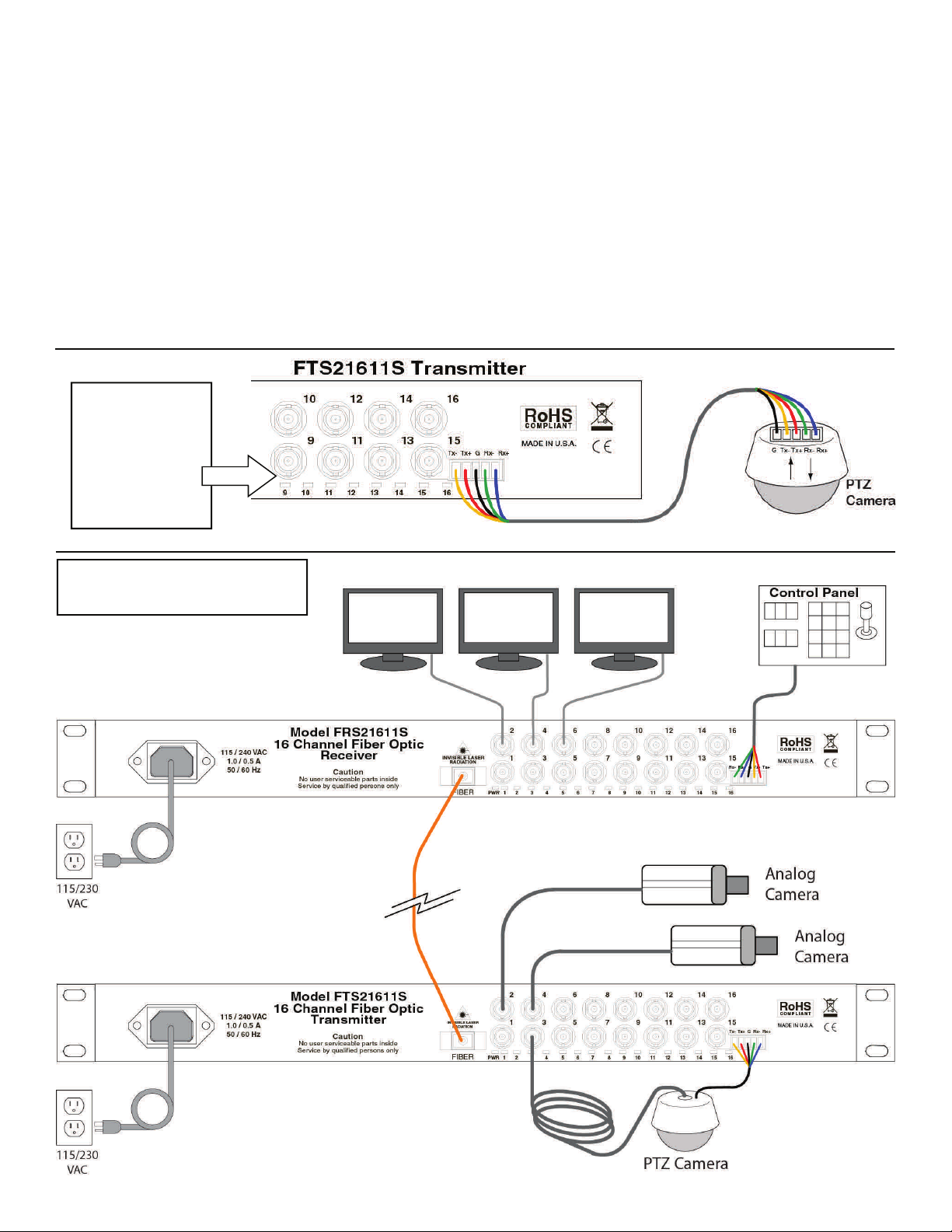
Installation Instructions
Refer to the diagrams on the previous page and below for installation. Use best industry practices and follow all local
building codes. The chassis can be desktop or rack mounted.
1. For a rack-mount installation, use the appropriate screws to fix each side of bracket onto the rack.
2. Install the multichannel receiver FRS21611S or FRS20811S, as appropriate, at the monitoring end.
3. Connect the fiber cable between the receiver and transmitter using a SC fiber connector at each end.
4. Connect monitors and control panel to the video port and data port of the receiver unit. Data I/O on the receiver is
labeled as to what is plugged into it, in example; control panel Tx+ connects to receiver Tx+.
5. Connect PTZ cameras to the video ports and data port of the multichannel transmitter. Data I/O on the transmitter is
labeled as to what is plugged into it, in example; transmitter Rx+ connects to camera Rx+.
6. Connect the supplied AC line cords to the transmitter and receiver.
7. Plug the AC cords into either the wall outlet or power strip/surge protector.
Note there are no technical adjustments required during or after installation.
Data In and Out
are labeled for
connection type,
i.e. Tx+ from
transmitter goes
to the Tx+ of the
camera.
Common Installation for a
16 Channel Configuration
 Loading...