

Nitek FRS3xx000R00 User Manual
Installation Manual
POWER
VIDEO / OPTO
OPTO IN / OUT
CH1
CH2
NITEK
R
CH1
CH2
CH3 CH4
POWER
VIDEO / OPTO
OPTO IN / OUT
CH1
CH2
CH3
CH4
NITEK
R
CH1
CH2
CH3
CH4
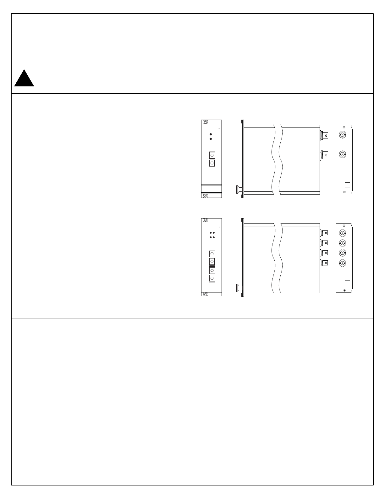
FRS3xx000R00 Rack Card
1, 2 and 4 Camera Rack Card
Note: This installation should be made by a qualified
service person and conform with local codes.
Reduce risk of fire or electrical shock do
not expose this product to rain or moisture.
!
Specifications
Video Connection
Connector 75 ohm BNC Socket
Input/Output Impedance 75 ohm terminated
Input/Output Level 1 volt p-p nominal
Frequency Response 10Hz to 5.75MHz
Optical Connection
Connector SC Style
Path Loss 20 dB
Wavelength 1310 / 1550nm
No Customer adjustments are available within the unit.
Dimensions
Width 1 Card slot
Power Connection
Provided from FSR1000 Card Rack
Model List
FRS311000R00 1 Ch Receiver
FRS322000R00 2 Ch Receiver
FRS344000R00 4 Ch Receiver
FTS344000R00 4 Ch Transmitter
NITEK ®
5410 Newport Drive, Suite 24
Rolling Meadows, IL 60008
PHONE (847) 259-8900
FAX (847) 259-1300
WWW.NITEK.NET
680600120 Rev 02202009
CH1
CH2
CH1
CH2
Installation Instructions
- This fiber card is designed to be mounted in the FSR1000 Fiber Card Rack.
- Always allow for bend radius of optical and electrical cables when installed.
- There are no adjustments required when using this product.
Service Information
There are no user serviceable parts inside the unit. In the event that service is required to this unit please
contact NITEK Technical Support at 800-528-4343.
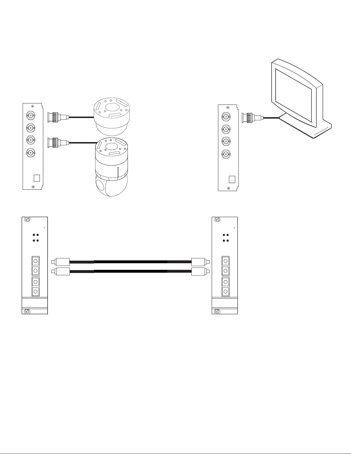
Typical Installation Diagram
CH1
CH3 CH4
CH2
Transmitter
Back Panel
NITEK
OPTO IN / OUT
CH1
CH2
CH3
CH1
CH4
CH2
POWER
VIDEO / OPTO
R
Video In
(1 or more)
(connect to CH1,2, etc)
Back Panel
(connect to CH1,2, etc)
Receiver
NITEK
CH3
CH1
CH4
CH2
POWER
VIDEO / OPTO
OPTO IN / OUT
CH1
CH2
CH1
CH3 CH4
Video Out
(1 or more)
CH2
R
CH3
CH4
Transmitter
Front Panel
Single-Mode Fiber with SC Connectors
CH3
CH4
Receiver
Front Panel
 Loading...