

Nitek FRS312104R00, FRS324104R00 Installation Manual
Installation Manual
CH2
NITEK
CH1
POWER
VIDEO/OPTO
CH2
DATA OUT
DATA IN
ALARM OUT
ALARM IN
CH1
CH2
OPTO IN / OUT
CH2
NITEK
CH1
POWER
VIDEO/OPTO
CH2
DATA OUT
DATA IN
ALARM OUT
ALARM IN
CH1
CH2
OPTO IN / OUT
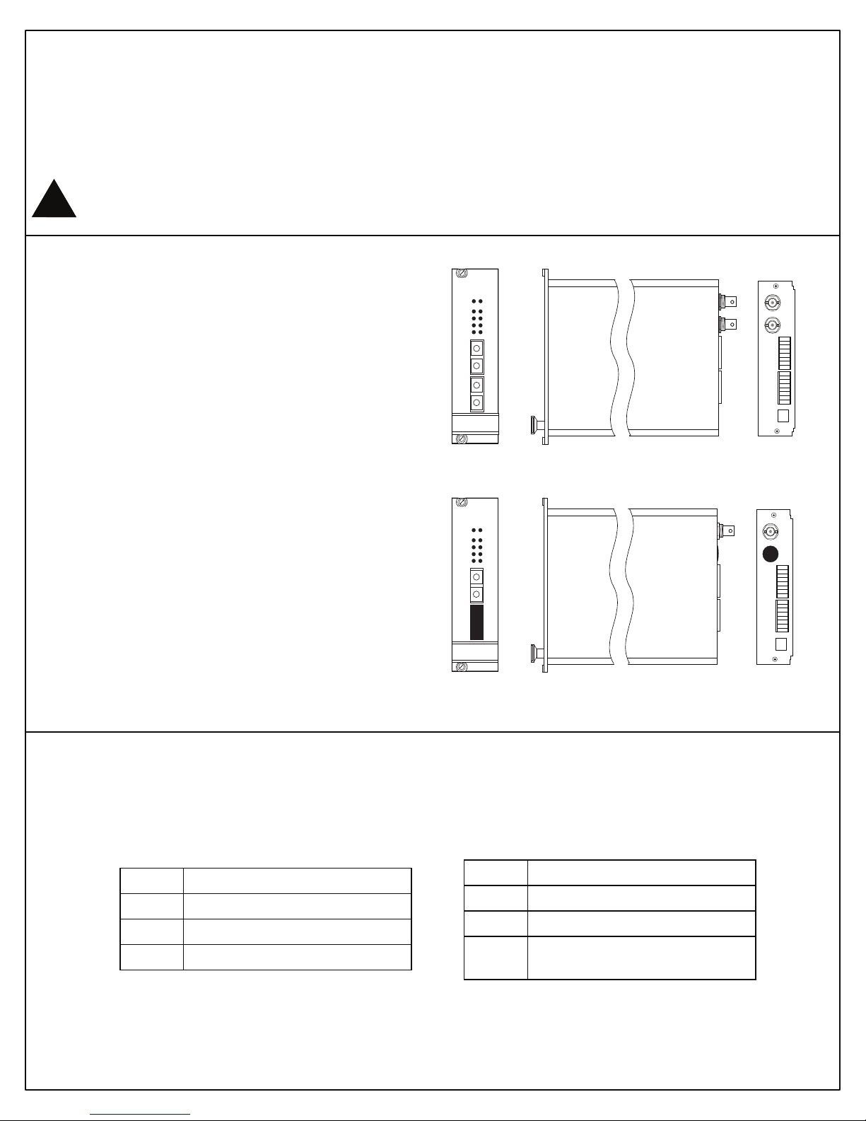
FRS312104R00 Single Receiver
FRS324104R00 Dual Receiver
1, 2 Camera Receiver w/Data and Aux Comm.
Note: This installation should be made by a qualified
service person and conform with local codes.
Reduce risk of fire or electrical shock do
!
not expose this product to rain or moisture.
Specifications
Video Connection
Connector 75 ohm BNC Socket
Output Impedance 75 ohm terminated
Output Level 1 volt p-p nominal
Frequency Response 10Hz to 5.75MHz
Optical Connection
Connector SC Style
Path Loss 20dB
Wavelength 1310 / 1550nm
Dimensions
Width 1 Card slot
Power Connection
Provided from FSR1000 Card Rack
Auxiliary Ports
Data Selectable RS422/RS485/RS232
Alarm In Contact Closure
Alarm Out Relay 100V / 150mA max
NITEK ®
5410 Newport Drive, Suite 24
Rolling Meadows, IL 60008
PHONE (847) 259-8900
FAX (847) 259-1300
WWW.NITEK.NET
680600125 Rev 02232009
CH1
FRS324104R00
CH1
FRS312104R00
Installation Instructions
- The fiber receiver is designed to be mounted in the FSR1000 Fiber Card Rack.
- Always allow for bend radius of optical and electrical cables when installed.
Data LED
Color Description
Green Data is Low / Logic 0
Red Data is High / Logic 1 (RS422/485)
Service Information
There are no user serviceable parts inside the unit. In the event that service is required to this unit please
Off Data is Tri-state / (High - RS232)
Yellow (RX) Link working, No video at TX
contact NITEK Technical Support at 800-528-4343.
Power/Video/Opto LED
Color Description
Green System Normal
Red (TX) Power on, No video into TX
(RX) Power on, No opto into RX
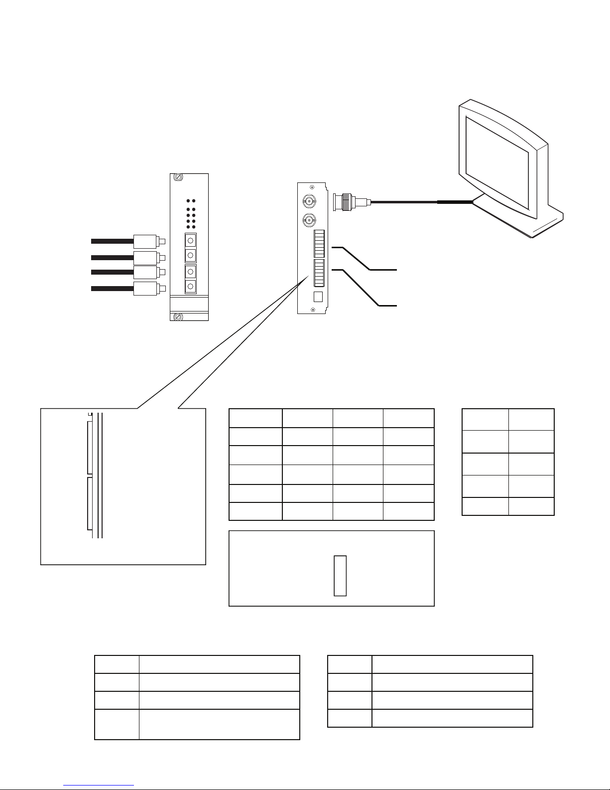
Typical Installation Diagram
Receiver
Front Panel
VIDEO/OPTO
ALARM OUT
Single-Mode Fiber
with SC Connectors
1
2
3
4
DATA / ALARM CH1
5
6
7
8
1
2
3
4
DATA / ALARM CH2
5
6
7
8
Data Connections
AUX COMM IN / OUT
DEPENDING ON SWITCH SETTING
NITEK
CH2
CH1
POWER
DATA OUT
DATA IN
ALARM IN
OPTO IN / OUT
CH1
CH2
Receiver
Back Panel
CH1
CH2
Video Out
(1 or more)
Data In
Aux Comm In / Out
(depending on model)
Rear Panel Data Connections
Data RS485 RS422 RS232
IN + (A) 7 1 2
IN - (B) 8 2 --
OUT + (A) 7 7 8
OUT - (B) 8 8 --
GND 6 6 6
Set Data Format with Internal Switch
RS485
Data CH1
RS422
RS232
Alarm Connections
Alarm Pin
OUT + 3
OUT - 4
IN + 5
GND 6
Power/Video/Opto LED
Color Description
Green System Normal
Yellow (RX) Link working, No video at TX
Red (TX) Power on, No video into TX
(RX) Power on, No opto into RX
Data LED
Color Description
Green Data is Low / Logic 0
Red Data is High / Logic 1 (RS422/485)
Off Data is Tri-state / (High - RS232)
 Loading...