

Nitek FRS2020 User Manual
Model FRS2020 19” Rack Mount Chassis
with Dual Power Supply System
Reduce risk of fire or electrical shock. Do not
expose this product to rain or moisture.
Note: This installation should be made by a qualified
service person and conform with local codes.
Installation and
Operation Manual
Introduction
The Nitek FRS2020 unit provides a means of centralizing individual video data modules, from the FSS20111S system,
together in a single chassis. The FRS2020 uses the standardized dimensions for a 19 inch 2-Unit rack mounted
chassis. The chassis can accommodate, in any combination, of up to 16 video card modules from the FSS20111S
system. The chassis design supports ‘hot swapping’ of the FSS20111S ‘plug and play’ video cards, allowing the system
to be powered up while cards are removed and installed. The FRS2020 is configured as a dual power supply, both
power supplies work independently from each other. In the case of a major failure by one of the power supplies the
other supply will continue to provide the proper power to all of the video cards.
Safety
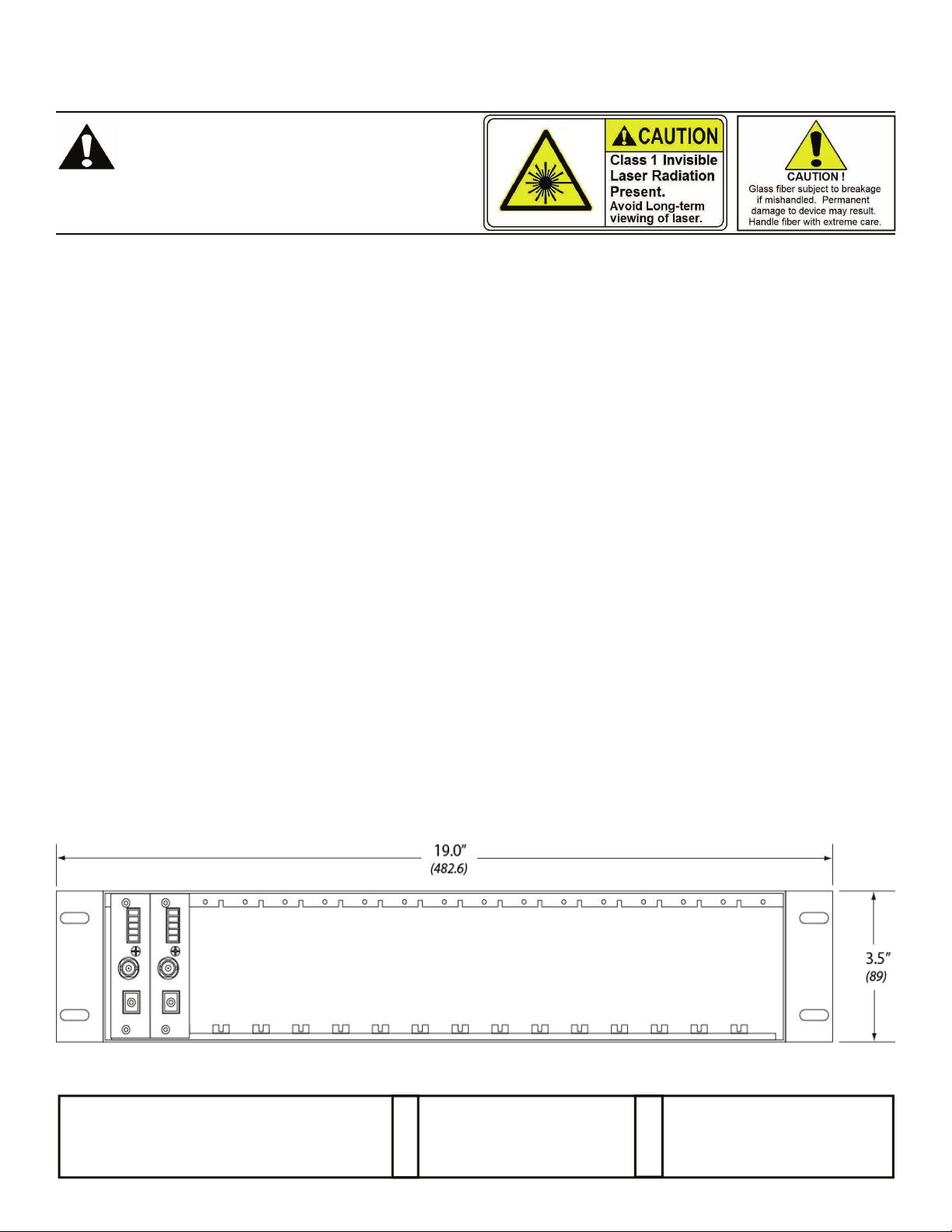
The FSS20111S uses a Class 1 laser system in accordance with IEC 60825-1.
It is always advisable to follow good practice when working with optical fiber systems. This includes:
• Do not stare with unprotected eyes at fiber ends or connector faces.
• Use only approved filtered or attenuating viewing devices.
• For other safety issues and advice on good practices associated with optical fiber systems see IEC 60825-1 or your
local safety officer
.
Device Mounting Options
The FRS2020 can be either rack mounted, or resting on a desktop.
NOTES:
1. Use all four mounting screws to properly secure the unit to the rack.
2. Mechanical loading - The mounting ears were designed for two ears to support one unit.
3. Air-Flow - Leave space on the rear of the unit for airflow into cooling fans on back of the unit. Adequate air flow
is required for safe operation.
4. Cable space - Allow for proper bend radius of the fiber cables exiting the front of the unit. Do not exceed the
recommended minimum bend radius of the fiber cable.
Front View
680160112
NITEK ®
5410 Newport Drive, # 24
Rolling Meadows, IL 60008
Phone: (847) 259-8900
Fax: (847) 259-1300
USA
E-mail: info@nitek.net
WWW.NITEK.NET
De Schans 19-21 2a
8231 KA Lelystad
Tel: +31(0)320-230005
E-mail: info@nitek.nl
WWW.NITEK.NL
EUROPE
09172013
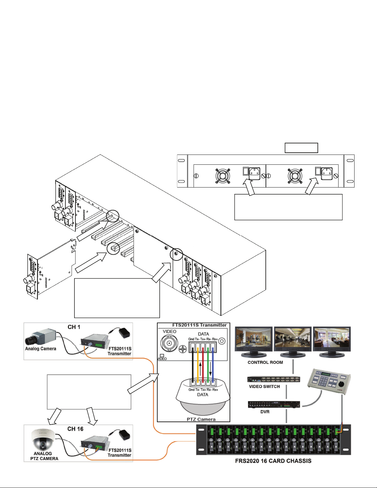
Installation Instructions
Refer to the diagrams on the previous page and below for installation. Use best industry practices and follow all local
building codes. The chassis can be desktop or rack mounted.
1. For a rack-mount installation, use the appropriate screws to fix each side of bracket onto the rack.
2. Remove the two Hex Head screws on the front of the unit and pull the card unit out of the wall mount chassis.
3. Install the Receiver/Transmitter card (up to 16) by sliding in the card along the plastic card guides, making sure that
the card is properly is all the way in and properly inserted into the backplane connector.
4. Screw in the thumb/hex head screw on the top of the face plate to firmly secure the card in the unit.
5. Connect monitors and control panel to the video port and data port of each receiver card module respectively.
6. Connect PTZ cameras to the video port and data port of each transmitter.
7. Connect the supplied AC line cord to the 2 power supplies in the chassis and plug in the cords to the AC wall outlet
and turn on the 2 power supplies; connect the supplied power supply to the transmitter.
8. Connect, at the camera end, the supplied power supply to power the FTS20111S Transmitter.
Note there are no technical adjustment required during or after installation.
Typical Hook-up
Insert cards as shown, by
sliding the cards into the card
guides, use the supplied
mounting screw to secure the
card into the card rack.
Rear View
Both power cords must be plugged-in
and both power supplies turned-on, in
order to benefit from the dual set-up.
Data In and Out are labeled
for connection type, i.e. Tx+
from transmitter goes to the
Tx+ of the camera.
 Loading...