

Nitek EX560 User Manual

Model EX560Model EX560
Model EX560
Model EX560Model EX560
Active receiver for UTP Transmission
Installation and Operation Manual
EX560 includes TR560 Receiver
and TT560 Transmitter
Reduce risk of fire or electrical shock do
not expose this product to rain or moisture.
Rev. 110905
USA Office:
5410 Newport Drive • Rolling Meadows, IL 60008
Phone: (800) 528-4343
Fax: (847) 259-1300
E-mail: info@nitek.net • Web: www.nitek.net
NITEK
®
Europe Office (Netherlands):
De Schans 19-21 2a • 8231 KA Lelysted
Phone: +31(0)320 -230005
Fax: +31(0)320 -282186
E-mail: info@nitek.nl • Web: www.nitek.nl
Reduce risk of fire or electrical shock do not
expose this product to rain or moisture.
Installation
1) Check the twisted pair for continuity. Do this by shorting the pair
of wires at one end and use an ohm meter to check the resistance
at the other end. The chart below will give you the length of your
wires for a measured loop resistance. (For distances greater than
6,000 feet, there are several other systems available, contact your
local Distributor or NITEK Technical Support for assistance.)
Also use a multimeter to make sure there is no voltage on the
line, very high resistance to ground and an open circuit when the
short at the far end of the wires is removed.
eriW
egaG
005
)051(
0001
)003(
0002
)006(
0003
)009(
)SRETEM(TEEFNIECNATSID
0004
)0021(
0005
)0051(
0006
)0081(
2261234669821061291
425215201351402552603
621428461642823014294
2) Connect a video source to the BNC of the TT560 transmitter unit.
Connect the twisted pair to the terminals marked “WIRE PAIR +”
and “
-
”. Note the polarity of the connection. This will be needed
when connecting the receiver.
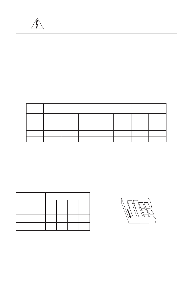
3) Set the DIP switches on the transmitter as follows. The settings
listed are for normal conditions.
ECNATSID
.tf0002<XX
.tf0002>NOXX
.tf0054>NONOXX
X = not used
NOITISOPHCTIWS
123 4
Example
Switches 1 and 2 are in “OFF” position
Switches 3 and 4 are in “ON” position
2
1
O
F
F
4
3
5) At the receiver end, connect the receiver BNC jack to a monitor
or DVR.
6) Connect the twisted pair to the terminals marked “WIRE PAIR +”
and “
-
”. Note the polarity of the connection should match the
 Loading...