

Nitek ER8400U User Manual
INSTALLATION GUIDE
ER8400U
8 Port Wall Mounted IP Video Extender Over UTP
With Built-In Gigabit PoE+ Switch and EtherStretch
Description
The ER8400U is another component of the NITEK cutting edge EtherStretch line. Our EtherStretch solution allows
for the utilization of existing cable infrastructure (coax or UTP) to transmit data from IP cameras and other network devices along with PoE+ power to operate these network devices over the given wire media well beyond the 100m/328ft
networking distance limitation. EtherStretch technology allows you to operate 100Mb Ethernet at over 600 meters.
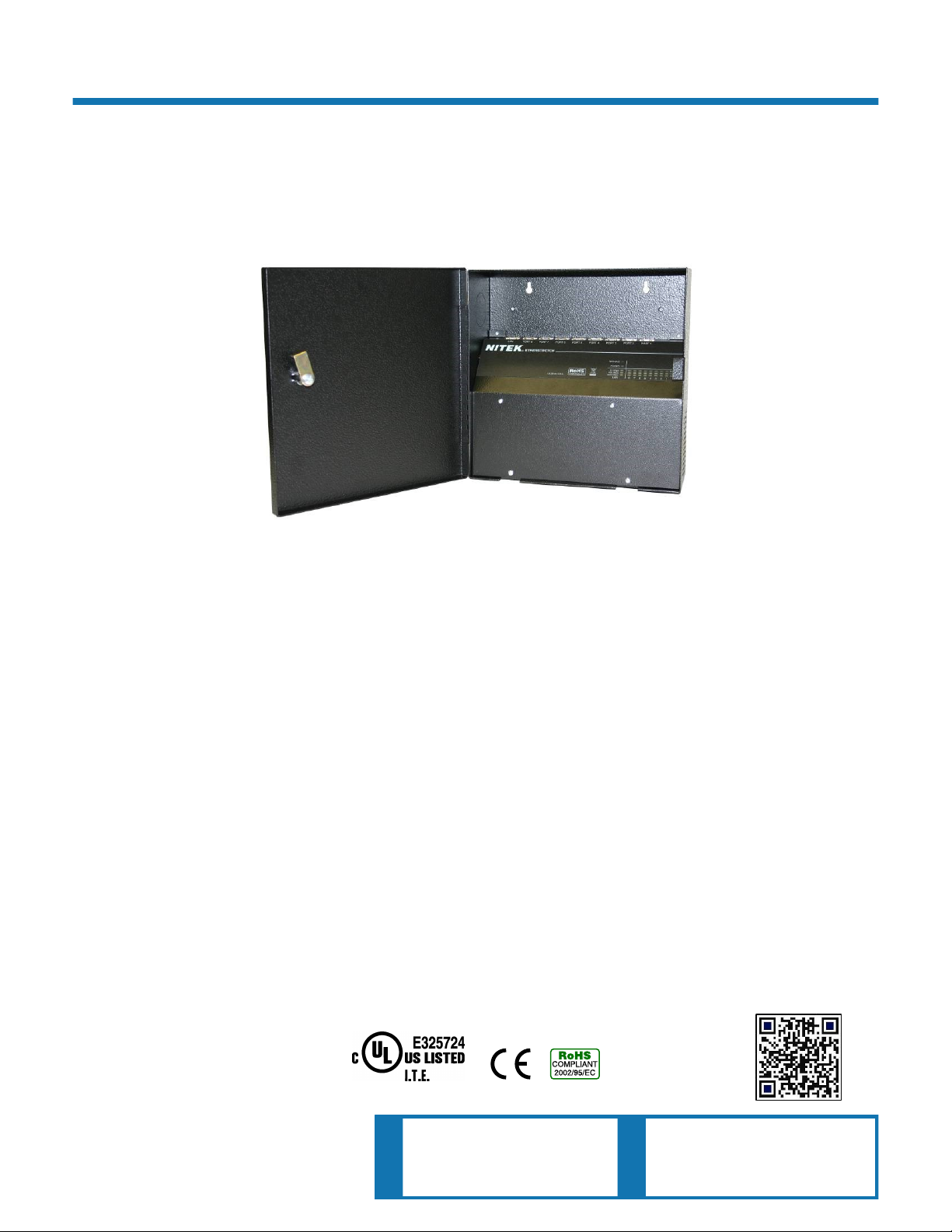
The ER8400U is a wall mounted eight port power sourcing receiver unit has built-in gigabit switching capabilities. The
unit requires very little installation time and absolutely no set up or configuration. The ER8400U and associated
ET1500U transmitters, up to 8, can quickly enable UTP CAT5e/CAT6 cables to support high speed network communication and PoE+ transmission to be extended to 600 meters or 2000 feet.
The ER8400U is a fully functional PoE+ network Layer 2 switch with IEEE802.3AT power output on each of the 8 network ports and a full Gigabit LAN jack. It allows you to mix standard Ethernet devices for distances of up to 100 meters
and with EtherStretch devices that can extend cable runs to 600 meters. The longer 600m/2000ft require the use of
the ET1500U transmitter. A small EtherStretch transmitter unit connects at the far end of the cable and allows you to
connect any Ethernet device to the cable and get 100Mb communication.
The ER8400U is completely transparent to the network thus requiring no IP and MAC addressing. Simply connect your
network device to the transmitter network port connect a new or existing cables to the receiver and the system quickly
begins communicating. LED indicators show the status and data speed of communications along with PoE power confirmation.
The NITEK EtherStretch ER8400U reliably extends network communications to overcome cable distance limitations
offering connectivity to devices in locations traditional networking does not allow. The ER8400U is ideal for retro -fitting
existing installations. The wall mounted unit is constructed of robust welded steel casing with a security lock and a built
in cooling and ventilation system.
Patent Pending
IEC/UL 60950-1
NITEK ®
5410 Newport Drive, # 24
Rolling Meadows, IL 60008
Phone: (847) 259-8900
Fax: (847) 259-1300
USA
E-mail: info@nitek.net
WWW.NITEK.NET
De Schans 19-21 2a
8231 KA Lelystad
Tel: +31(0)320-230005
E-mail: info@nitek.nl
WWW.NITEK.NL
EUROPE

Important Safety Instructions
Read all Safety Instructions.
Keep the Instructions for future reference.
Be sure to HEED all Warnings.
Follow ALL instructions.
DO NOT use this device or any of the equipment described, near water.
Clean this device ONLY with a dry cloth.
DO NOT block any ventilation openings.
Install in accordance with the manufacturer’s instructions.
DO NOT install near any heat sources such as radiators, heat registers, stoves or other apparatus (including
amplifiers) that produce heat.
DO NOT defeat the safety purposes of polarized or grounding type plugs. A polarized plug has two blades, with
one blade wider than the other. A grounding plug has two blades and has a third grounding prong. The wide
blade and the grounding prong are provided for your safety. If the provided plug does not fit into your outlet,
consult an electrician for replacement of the obsolete outlet.
DO NOT connect the unit to an electrical supply if the wiring or over current protection of the supply could be
overloaded when the ratings listed on the unit are considered.
Protect the power cord from being walked on or pinched especially at plugs, convenience receptacles and other
points where they exit from the device.
Only use attachments and/or accessories specified by the manufacturer.
Refer all servicing to qualified service personnel. Servicing is required when the device has been damaged in any
way, such as the power supply cord or plug is damaged, liquid has been spilled on, or objects have fallen into the
device, the device has been exposed to rain or moisture, does not operate normally or has been dropped.
WARNING: To reduce risk of fire or electric shock, do not expose this apparatus to rain or moisture.
Installation shall be performed ONLY by qualified personnel and must conform to all local codes.
Unless the device is specifically marked as a NEMA 3, 3R, 3S, 4, 4X, 6 or 6P enclosure, it is designed for indoor
use ONLY and it must not be installed where exposed to rain or moisture.
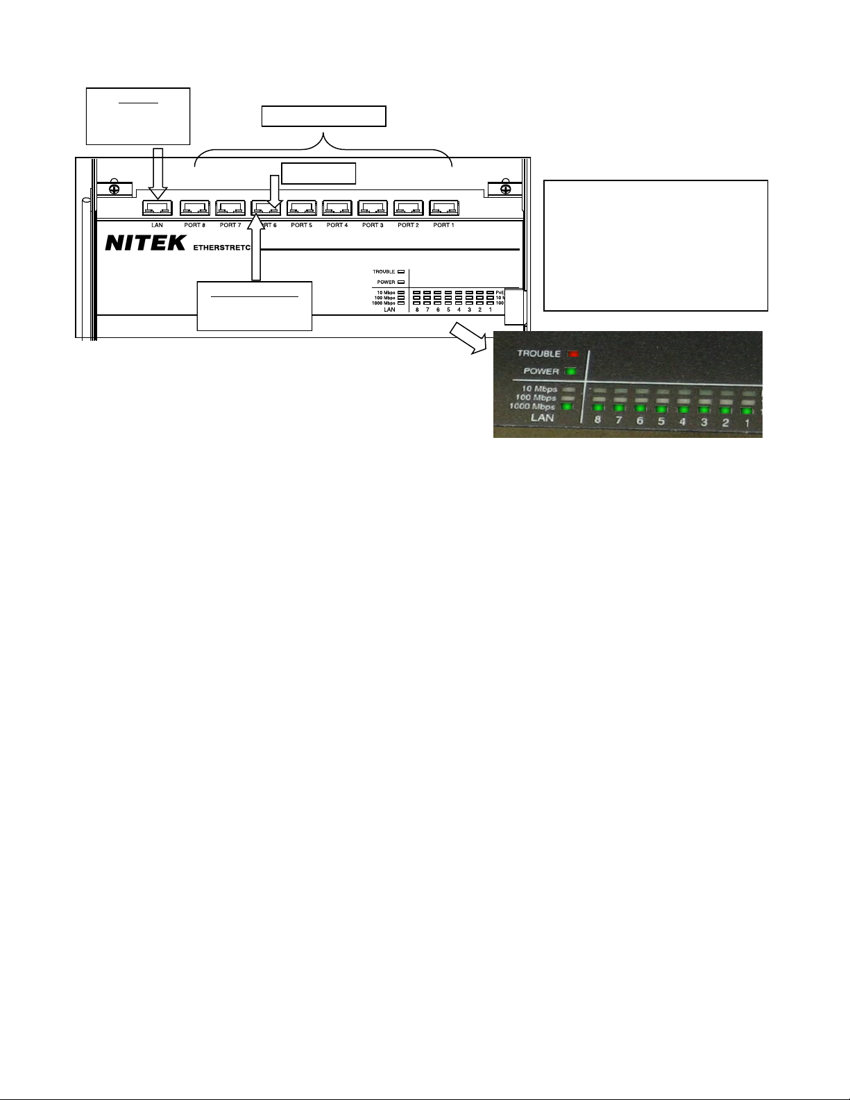
Parts of the ER8400U (Front Panel)
LAN Port
Green = 1Gb
YellowYellowYellow = 100Mb
Orange = 10Mb
Network Connection
Green = 100Mb
Orange = 10Mb
RJ45 Network Ports
PoE OUT
The LED Display Panel shows the same
LED Display Panel
information as the individual jacks does but
in a easier to read location. It also shows
Power indicator and a Trouble LED.
Trouble LED
Solid if there is a temperature problem
Flashing Slow is a network loop problem
Installation Considerations
Wire and Cable Recommendations: The ER8400U is designed for use with up to 8 UTP CAT5e/CAT6 24AWG
(American Wire Gauge) cables. The quality and condition of which must be considered serviceable Category type
cable. It must be free from damage such as cuts, breaks or cracks to the outer covering and insulated shielding
which may compromise the signal conductivity of the cables.
For more specific information regarding wire types, gauges, and proper installation techniques please call Tech
Support at (800) 528-4343.
Ethernet & PoE: The ER8400U is designed to communicate at up to 100Mbps per network port for Ethernet data
and transmit up to 1 Gigabit of aggregate LAN traffic. Additionally, the ER8400U provides per port power sourcing
PoE+ voltage to operate the transmitters (ET1500U), and up to 8 attached network devices. As a power sourcing
Layer 2 switch the ER8400 will supporting 15.4W (802.3af) to 25.5W (802.3at) powering schemes at a maximum
distance of 2000ft or 600m. Refer the PoE distance chart for specific power capabilities. Before installing this solution be sure that the cable involved does not exceed the recommended maximum lengths. If the cable length is indeterminist at the time of installation, we recommend the use of a time domain reflectometer (TDR) which can
measure impedance characteristics, splices, and determine the cable length. The TDR does this through the use of
short rise time pulses.
Installation & Setup
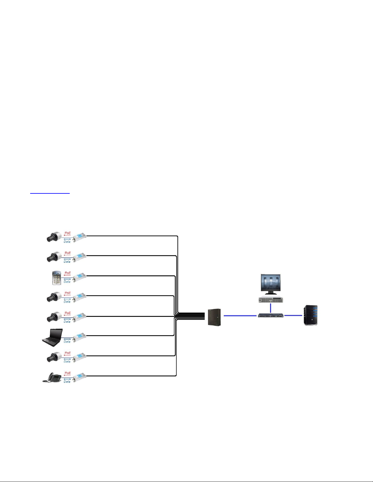
Equipment Requirements & Mounting: The process for installing the ER8400U is rather quick and easy. A com-
mon topology involves up to 8 new or existing UTP cables (not exceeding 2000ft / 600m), up to 8 ET1500U transmitters and up to 8 IP cameras or other peripheral network devices. The wall mounted ER8400U, which can be referred to as the NITEK Power Sourcing Equipment (PSE), is compliant with both 802.3AF and 802.3AT devices. All
network connections should have RJ45 terminations and be in accordance with 568B pin out standards.
The method for facilitating Ethernet communication and PoE over UTP CAT5e/CAT6 cable starts with connecting
the ER8400U to a series of up to 8 UTP cables via its network ports. Each of the UTP cables interface with the IP
camera via the ET1500U transmitter, located at the camera end of the UTP cable. The IP camera establishes connectivity to ET1500U transmitter via RJ5 jacks and a CAT5e/CAT6 patch cords. For cables shorter than 100 meters
the IP camera may be directly connected to the ER8400U. The ER8400U powers all attached devices within this
system. The Ethernet data from the camera is transmitted over each individual UTP cable through the ET1500U to
the wall mounted ER8400U in either the IDF or MDF. The aggregate Ethernet data is transmitted to the LAN port
via a built-in Layer 2 switch of the ER8400U. The Gigabit LAN port to ensure congestion-free throughput. An illustration of this system is shown below in the “Installment Topology” diagram.
Upon power up the devices will undergo initialization and auto-configuration which may take a number of seconds
(time variations are device, installation and topology dependent) to complete before PoE and Ethernet communication commences. For optimal performance referring to the PoE Distance Chart later in this manual. Also adhering to
the IP camera operational specifications is recommended. If issues arise during the installation process please see
the “Trouble Shooting Tips” section later in this manual. You may also contact our web based live tech support at:
www.nitek.net or call (800) 528-4343 in order to speak with one of our engineers directly.
Installment Topology
 Loading...