

Nitek ER16500C User Manual
INSTALLATION GUIDE
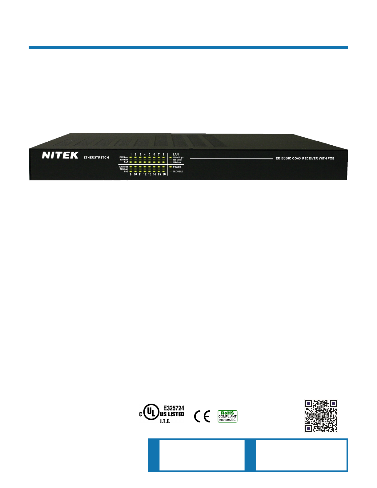
ER16500C
16 Port IP Video Extender Over Coax
With Built-In Gigabit PoE Switch with EtherStretch
Description
The ER16500C is another component of the NITEK cutting edge EtherStretch line. Our EtherStretch solution allows for the utilization of existing cable infrastructure (coax or UTP) to transmit data from IP cameras
and other network devices along with power (PoE & PoE+) to operate these networked devices over the given copper media well over the 100 meter or 328 feet networking distance limitation.
The ER16500C is a Ethernet & PoE extending rack mounted sixteen port, power sourcing receiver unit with
built-in Gigabit switching capabilities. The unit requires very little installation time and absolutely no set up or
configuration. Independently the ER16500C will work as a Layer 2 PoE+ switch. Additionally, the ER16500C
and associated ET1500C transmitters (up to 16) can quickly turn ordinary coaxial cables into a series of high
speed network communication and PoE pathways. The ER16500C is a fully functional Layer 2 PoE+ network
switch with a 802.3AT power output on each of the sixteen network ports. Additionally, when used with the
ET1500C transmitters the system allows for cable runs of up to 500m/1600ft supplying both a network connection and PoE+ power.
The ER16500C is completely transparent to the network thus requiring no IP and MAC addressing. Simply
connect your network devices to the transmitter LAN ports along with the existing cables to the receiver and
the system quickly begins communicating. LED indicators show the status and data speed of network communications along with PoE power confirmation.
NITEK EtherStretch ER16500C reliably extends network communications to overcome cable distance limitations offering connectivity to devices in locations traditional networking does not allow. The ER16500C is
ideal for retro-fitting existing installations. The rack mounted unit is robustly constructed of molded steel casing with appropriate built in cooling and ventilation.
Patent Pending
IEC/UL 60950-1
NITEK ®
5410 Newport Drive, # 24
Rolling Meadows, IL 60008
Phone: (847) 259-8900
Fax: (847) 259-1300
USA
E-mail: info@nitek.net
WWW.NITEK.NET
De Schans 19-21 2a
8231 KA Lelystad
Tel: +31(0)320-230005
E-mail: info@nitek.nl
WWW.NITEK.NL
EUROPE

Important Safety Instructions
Read all Safety Instructions.
Keep the Instructions for future reference.
Be sure to HEED all Warnings.
Follow ALL instructions.
DO NOT use this device or any of the equipment described, near water.
Clean this device ONLY with a dry cloth.
DO NOT block any ventilation openings.
Install in accordance with the manufacturer’s instructions.
DO NOT install near any heat sources such as radiators, heat registers, stoves or other apparatus (including
amplifiers) that produce heat.
DO NOT defeat the safety purposes of polarized or grounding type plugs. A polarized plug has two blades, with
one blade wider than the other. A grounding plug has two blades and has a third grounding prong. The wide
blade and the grounding prong are provided for your safety. If the provided plug does not fit into your outlet,
consult an electrician for replacement of the obsolete outlet.
DO NOT connect the unit to an electrical supply if the wiring or over current protection of the supply could be
overloaded when the ratings listed on the unit are considered.
Protect the power cord from being walked on or pinched especially at plugs, convenience receptacles and other
points where they exit from the device.
Only use attachments and/or accessories specified by the manufacturer.
Refer all servicing to qualified service personnel. Servicing is required when the device has been damaged in any
way, such as the power supply cord or plug is damaged, liquid has been spilled on, or objects have fallen into the
device, the device has been exposed to rain or moisture, does not operate normally or has been dropped.
WARNING: To reduce risk of fire or electric shock, do not expose this apparatus to rain or moisture.
Installation shall be performed ONLY by qualified personnel and must conform to all local codes.
Unless the device is specifically marked as a NEMA 3, 3R, 3S, 4, 4X, 6 or 6P enclosure, it is designed for indoor
use ONLY and it must not be installed where exposed to rain or moisture.
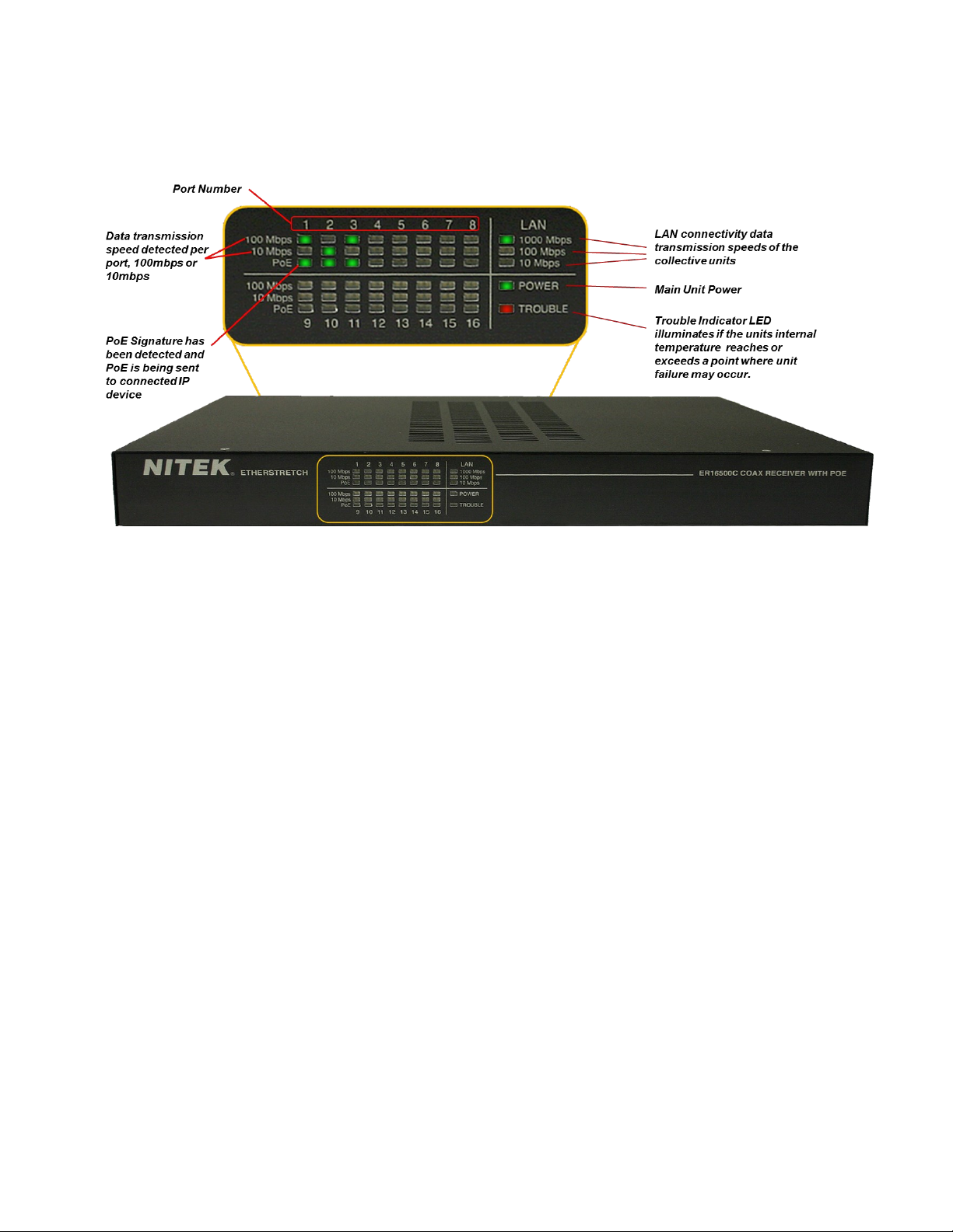
Parts of the ER16500C (Front Panel)
Installation & Setup
Installation Considerations
Wire and Cable Recommendations: The ER16500C is designed for use with up to sixteen (16)
RG59U 75 Ohm copper based 18 or 20 AWG (American W ire Gauge) coaxial cables. The quality
of which must be consistent with any reasonably serviceable cable condition. That is free from
damage as in cuts, breaks, or cracks to the outer covering and insulated shielding which may
compromise the signal conductivity of the cable.
For more specific information regarding wire types, gauges, and proper installation techniques
please call Tech Support at 1-(800)528-4343.
Ethernet & PoE: The ER16500C is designed to receive up to 100Mbps (per port) of Ethernet
TCP/IP data and transmit up to 1 Gigabit of aggregate LAN traffic. Additionally, the ER16500C
provides per port sourcing PoE to operate the transmitter (ET1500C), and all attached network
devices (up to 16) while supporting 15.4W (802.3af) to 25.5W (802.3at) powering schemes at a
maximum distance of 1,600ft./500m. Before considering this solution be sure that the cable involved do not exceed the recommended maximum lengths. If the cable value is indeterminate at
the time of installation, we recommend the use of a time domain reflectometer (TDR) which
through the use of short rise time pulses can measure impedance characteristics, splices, and
unknown cable distance estimates.

Parts of the ER16500C (Rear Panel)
Device Mounting Options
Rack Mounting
Back
Front
The ER16500C can be rack mounted, wall mounted or used as desk top unit. Use the included mounting ears in the
front or back of the unit depending on your needs. The mounting ears can also be turned to the bottom of the unit
for wall mounting if needed. When mounting the unit, be sure to follow these guide lines.
a. Operating Ambient - Do not install the unit in an assembly where the ambient temperature could exceed
52°C (125°F). NOTE: the ambient temperature in a closed or multi-unit rack assembly could greatly exceed
the ambient temperature outside that assembly.
b. Air-Flow – Leave space on the sides of the unit for airflow into the cooling fans and some space on top of the
unit for air to exit the unit. Adequate air flow is required for safe operation.
c. Mechanical Loading – The mounting ears were designed for two ears to support one unit. Other
configurations, such as mounting other equipment directly on top of the unit or using only one mounting ear,
could cause a hazardous condition due to uneven or excessive mechanical loading.
Front
Wall Mounting
Back
 Loading...