

Nitek EL4500C, ER1500C Installation And Operation Manual
Model EL4500C (for use with Coaxial cable)
Installation and
Includes one ET4500C Transmitter
Operation Manual
and one ER1500C Receiver
Reduce risk of fire or electrical shock. Do not
expose this product to rain or moisture.
Note: This installation should be made by a
qualified service person and conform with local
codes.
Introduction
The EL4500C system uses a four channel transmitter and a single channel receiver to extend Ethernet & PoE. The
EL4500C can be used on new or existing cable and is designed to greatly extend the distances to which IP cameras and
network devices can operate. In addition to network communication the EL4500C is ideal for PoE applications. It allows
all power to flow from the head end for most camera applications. In unique cases where high power PoE is needed it
can inject up to 25 watts of power at the transmitter end.
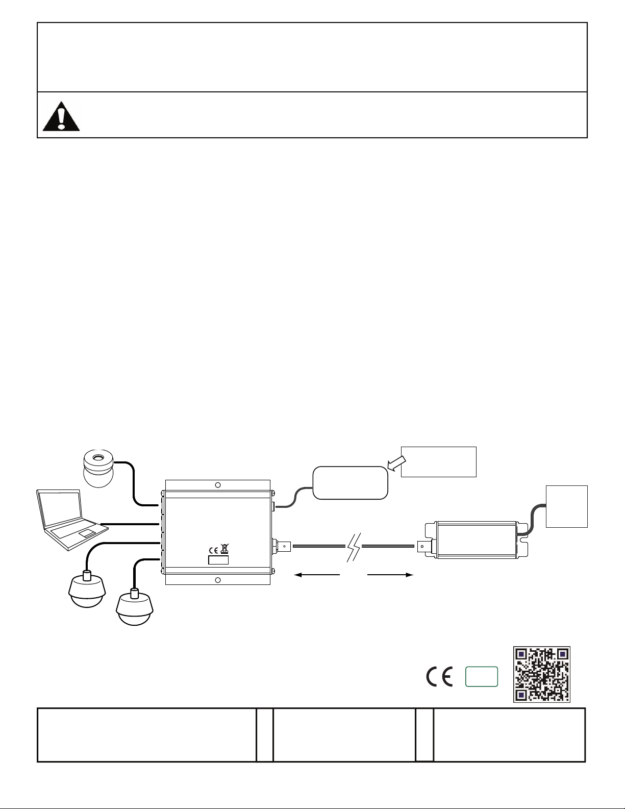
TYPE 1 Installation
Install EL4500C with a PoE Source Switch and IP Cameras
Refer to the
exceeding 1,640ft / 500m, the EL4500C transmitter and receiver pairs (ET4500C & ER1500C), an IP camera or other
peripheral network device (both universally referred to as the Power Device or PD), and a 3rd party PoE network switch
or Power Sourcing Equipment/PSE. Refer to the PoE power chart to determine maximum range for a PoE camera.
The method for facilitating Ethernet communication and PoE over RG59U cable starts with connecting the ER1500C to
the Power Sourcing Equipment, usually a switch (RJ45-to-RJ45) via a CAT5e/CAT6 patch cable. The ER1500C coax
BNC connector enables connectivity to the length of RG59U coax cable at the head end. The IP camera interfaces with
the ET4500C via RJ45 and a CAT5e/CAT6 patch cords. The output of the ET4500C intern connects to the length of
RG59U cable by its BNC connector at the camera end. Power from the PSE provides operational PoE for both
EL4500C units and the camera.
diagram below when installing. A common topology involves a length of existing coax cable up to but not
IP Camera
IP
NITEK
Por t 1
ET4500C
IP
Transmitter
Por t 2
IP
Por t 3
IP
Por t 4
IP Camera
IP Camera
Patent Pending
NITEK ®
681200144
RoHS
COMPLIANT
DC
Input
Link
Por t
5410 Newport Drive, # 24
Rolling Meadows, IL 60008
Phone: (847) 259-8900
Fax: (847) 259-1300
USA
E-mail: info@nitek.net
WWW.NITEK.NET
48Vdc @ 1Amp
Power Supply
500m
1640ft
RG59 Coaxial Cable
Optional PS48
(Not Included)
ER1500C
Link
NITEK
Por t
Receiver
RoHS
COMPLIANT
2002/95/EC
De Aar 99
8253 PN Dronten
The Netherlands
Tel: +31(0) 321 320 043
E-mail: info@nitekeurope.net
WWW.NITEK.NET
EUROPE
PoE
Switch
04082014
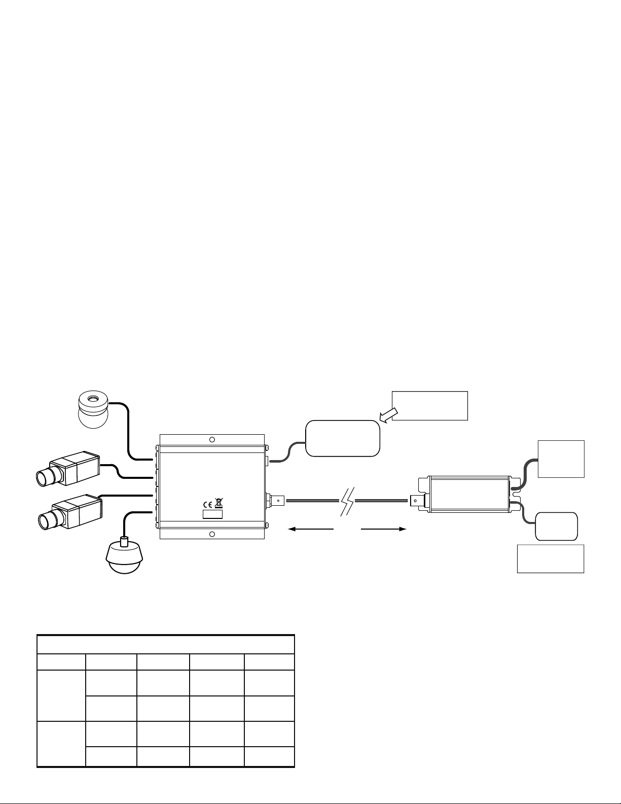
TYPE 2 Installation
Install EL4500C for Powering High Power PoE Cameras
Refer to the d
iagram below when installing. When installing without a PoE source device, the ER1500C can be powered
directly and will provide power for both the transmitter and PoE camera. The ET4500C can be used with a PS48 power
supply (available separately from Nitek) to power cameras up to 25 watts. When installing without a PoE source device,
the ER1500C must be powered directly.
A common topology involves a length of existing coax cable up to but not exceeding 1,640ft / 500m, the EL4500C
transmitter and receiver pairs (ET4500C & ER1500C), an IP camera or other peripheral network device (both universally
referred to as the Power Device or PD), and a 3rd party PoE network switch or Power Sourcing Equipment/PSE. The
PD and PSE must both be either 802.3af or 802.3at compliant. That is requiring or producing no more then 15.4 W
48VDC @ 350mA of 802.3af up to 25.5W 60VDC @ 600mA of 802.3at PoE+ power for proper attached device
operation.
The method for facilitating Ethernet communication and PoE over RG59U cable starts with connecting the ER1500C to
the Power Sourcing Equipment, usually a switch (RJ45-to-RJ45) via a CAT5e/CAT6 patch cable. The ER1500C coax
BNC connector enables connectivity to the length of RG59U coax cable at the head end. The IP camera interfaces with
the ET4500C via RJ45 and a CAT5e/CAT6 patch cords. The output of the ET4500C intern connects to the length of
RG59U cable by its BNC connector at the camera end. Power from the PSE provides operational PoE for both
EL4500C units and the camera.
Upon final power up the devices will under go initialization and auto-configuration processes (see LED Indicator chart)
which may take a number of seconds, time variations are device/installation/topology parameter dependent, to complete
before PoE and Ethernet communication commences. For optimal performance referring to the PoE Distance Chart and
adhering to the IP camera operational specifications is recommended.
IP Camera
(25W Camera)
IP
Por t 1
IP
Por t 2
IP
Por t 3
IP
Por t 4
NITEK
ET4500C
Transmitter
RoHS
COMPLIANT
DC
Input
Link
Por t
(25W Camera)
IP Camera
LED INDICATORS
Connector LED OFF ON FLASHING
Network
Port
Link
Port
PoE Out
Link Status
Power No Power
10/100 No Link 100Mb 10Mb
No PoE
Power Out
No Ethernet
Link
PoE Power
Good
Ethernet Link
Good
Power
Good
Power Supply
48 - 56Vdc
@ 1 - 5 Amp
500m
1640ft
RG59 Coaxial Cable
Optional PS48
(Not Included)
Link
Por t
ER1500C
NITEK
Receiver
Standard
Switch
PS48
48Vdc
Optional PS48
(Included)
 Loading...